EP4174233A1 - Elektrische arbeitsmaschine mit akkukühlung - Google Patents
Elektrische arbeitsmaschine mit akkukühlung Download PDFInfo
- Publication number
- EP4174233A1 EP4174233A1 EP22175425.2A EP22175425A EP4174233A1 EP 4174233 A1 EP4174233 A1 EP 4174233A1 EP 22175425 A EP22175425 A EP 22175425A EP 4174233 A1 EP4174233 A1 EP 4174233A1
- Authority
- EP
- European Patent Office
- Prior art keywords
- fan
- energy store
- cooling
- converter
- machine according
- Prior art date
- Legal status (The legal status is an assumption and is not a legal conclusion. Google has not performed a legal analysis and makes no representation as to the accuracy of the status listed.)
- Granted
Links
Images


Classifications
-
- E—FIXED CONSTRUCTIONS
- E02—HYDRAULIC ENGINEERING; FOUNDATIONS; SOIL SHIFTING
- E02D—FOUNDATIONS; EXCAVATIONS; EMBANKMENTS; UNDERGROUND OR UNDERWATER STRUCTURES
- E02D3/00—Improving or preserving soil or rock, e.g. preserving permafrost soil
- E02D3/02—Improving by compacting
- E02D3/046—Improving by compacting by tamping or vibrating, e.g. with auxiliary watering of the soil
- E02D3/068—Vibrating apparatus operating with systems involving reciprocating masses
-
- E—FIXED CONSTRUCTIONS
- E02—HYDRAULIC ENGINEERING; FOUNDATIONS; SOIL SHIFTING
- E02F—DREDGING; SOIL-SHIFTING
- E02F9/00—Component parts of dredgers or soil-shifting machines, not restricted to one of the kinds covered by groups E02F3/00 - E02F7/00
- E02F9/20—Drives; Control devices
- E02F9/2058—Electric or electro-mechanical or mechanical control devices of vehicle sub-units
- E02F9/2062—Control of propulsion units
- E02F9/207—Control of propulsion units of the type electric propulsion units, e.g. electric motors or generators
-
- H—ELECTRICITY
- H05—ELECTRIC TECHNIQUES NOT OTHERWISE PROVIDED FOR
- H05K—PRINTED CIRCUITS; CASINGS OR CONSTRUCTIONAL DETAILS OF ELECTRIC APPARATUS; MANUFACTURE OF ASSEMBLAGES OF ELECTRICAL COMPONENTS
- H05K7/00—Constructional details common to different types of electric apparatus
- H05K7/20—Modifications to facilitate cooling, ventilating, or heating
- H05K7/2089—Modifications to facilitate cooling, ventilating, or heating for power electronics, e.g. for inverters for controlling motor
- H05K7/20909—Forced ventilation, e.g. on heat dissipaters coupled to components
-
- E—FIXED CONSTRUCTIONS
- E01—CONSTRUCTION OF ROADS, RAILWAYS, OR BRIDGES
- E01C—CONSTRUCTION OF, OR SURFACES FOR, ROADS, SPORTS GROUNDS, OR THE LIKE; MACHINES OR AUXILIARY TOOLS FOR CONSTRUCTION OR REPAIR
- E01C19/00—Machines, tools or auxiliary devices for preparing or distributing paving materials, for working the placed materials, or for forming, consolidating, or finishing the paving
- E01C19/22—Machines, tools or auxiliary devices for preparing or distributing paving materials, for working the placed materials, or for forming, consolidating, or finishing the paving for consolidating or finishing laid-down unset materials
- E01C19/30—Tamping or vibrating apparatus other than rollers ; Devices for ramming individual paving elements
- E01C19/34—Power-driven rammers or tampers, e.g. air-hammer impacted shoes for ramming stone-sett paving; Hand-actuated ramming or tamping machines, e.g. tampers with manually hoisted dropping weight
-
- E—FIXED CONSTRUCTIONS
- E01—CONSTRUCTION OF ROADS, RAILWAYS, OR BRIDGES
- E01C—CONSTRUCTION OF, OR SURFACES FOR, ROADS, SPORTS GROUNDS, OR THE LIKE; MACHINES OR AUXILIARY TOOLS FOR CONSTRUCTION OR REPAIR
- E01C19/00—Machines, tools or auxiliary devices for preparing or distributing paving materials, for working the placed materials, or for forming, consolidating, or finishing the paving
- E01C19/22—Machines, tools or auxiliary devices for preparing or distributing paving materials, for working the placed materials, or for forming, consolidating, or finishing the paving for consolidating or finishing laid-down unset materials
- E01C19/30—Tamping or vibrating apparatus other than rollers ; Devices for ramming individual paving elements
- E01C19/34—Power-driven rammers or tampers, e.g. air-hammer impacted shoes for ramming stone-sett paving; Hand-actuated ramming or tamping machines, e.g. tampers with manually hoisted dropping weight
- E01C19/35—Hand-held or hand-guided tools
-
- E—FIXED CONSTRUCTIONS
- E02—HYDRAULIC ENGINEERING; FOUNDATIONS; SOIL SHIFTING
- E02D—FOUNDATIONS; EXCAVATIONS; EMBANKMENTS; UNDERGROUND OR UNDERWATER STRUCTURES
- E02D3/00—Improving or preserving soil or rock, e.g. preserving permafrost soil
- E02D3/02—Improving by compacting
- E02D3/046—Improving by compacting by tamping or vibrating, e.g. with auxiliary watering of the soil
-
- E—FIXED CONSTRUCTIONS
- E02—HYDRAULIC ENGINEERING; FOUNDATIONS; SOIL SHIFTING
- E02F—DREDGING; SOIL-SHIFTING
- E02F9/00—Component parts of dredgers or soil-shifting machines, not restricted to one of the kinds covered by groups E02F3/00 - E02F7/00
- E02F9/08—Superstructures; Supports for superstructures
- E02F9/0858—Arrangement of component parts installed on superstructures not otherwise provided for, e.g. electric components, fenders, air-conditioning units
- E02F9/0866—Engine compartment, e.g. heat exchangers, exhaust filters, cooling devices, silencers, mufflers, position of hydraulic pumps in the engine compartment
-
- F—MECHANICAL ENGINEERING; LIGHTING; HEATING; WEAPONS; BLASTING
- F16—ENGINEERING ELEMENTS AND UNITS; GENERAL MEASURES FOR PRODUCING AND MAINTAINING EFFECTIVE FUNCTIONING OF MACHINES OR INSTALLATIONS; THERMAL INSULATION IN GENERAL
- F16F—SPRINGS; SHOCK-ABSORBERS; MEANS FOR DAMPING VIBRATION
- F16F15/00—Suppression of vibrations in systems; Means or arrangements for avoiding or reducing out-of-balance forces, e.g. due to motion
- F16F15/02—Suppression of vibrations of non-rotating, e.g. reciprocating systems; Suppression of vibrations of rotating systems by use of members not moving with the rotating systems
- F16F15/04—Suppression of vibrations of non-rotating, e.g. reciprocating systems; Suppression of vibrations of rotating systems by use of members not moving with the rotating systems using elastic means
- F16F15/08—Suppression of vibrations of non-rotating, e.g. reciprocating systems; Suppression of vibrations of rotating systems by use of members not moving with the rotating systems using elastic means with rubber springs ; with springs made of rubber and metal
-
- H—ELECTRICITY
- H01—ELECTRIC ELEMENTS
- H01M—PROCESSES OR MEANS, e.g. BATTERIES, FOR THE DIRECT CONVERSION OF CHEMICAL ENERGY INTO ELECTRICAL ENERGY
- H01M10/00—Secondary cells; Manufacture thereof
- H01M10/60—Heating or cooling; Temperature control
- H01M10/61—Types of temperature control
- H01M10/613—Cooling or keeping cold
-
- H—ELECTRICITY
- H01—ELECTRIC ELEMENTS
- H01M—PROCESSES OR MEANS, e.g. BATTERIES, FOR THE DIRECT CONVERSION OF CHEMICAL ENERGY INTO ELECTRICAL ENERGY
- H01M10/00—Secondary cells; Manufacture thereof
- H01M10/60—Heating or cooling; Temperature control
- H01M10/63—Control systems
-
- H—ELECTRICITY
- H01—ELECTRIC ELEMENTS
- H01M—PROCESSES OR MEANS, e.g. BATTERIES, FOR THE DIRECT CONVERSION OF CHEMICAL ENERGY INTO ELECTRICAL ENERGY
- H01M10/00—Secondary cells; Manufacture thereof
- H01M10/60—Heating or cooling; Temperature control
- H01M10/65—Means for temperature control structurally associated with the cells
- H01M10/656—Means for temperature control structurally associated with the cells characterised by the type of heat-exchange fluid
- H01M10/6561—Gases
- H01M10/6563—Gases with forced flow, e.g. by blowers
-
- H—ELECTRICITY
- H05—ELECTRIC TECHNIQUES NOT OTHERWISE PROVIDED FOR
- H05K—PRINTED CIRCUITS; CASINGS OR CONSTRUCTIONAL DETAILS OF ELECTRIC APPARATUS; MANUFACTURE OF ASSEMBLAGES OF ELECTRICAL COMPONENTS
- H05K7/00—Constructional details common to different types of electric apparatus
- H05K7/20—Modifications to facilitate cooling, ventilating, or heating
- H05K7/20009—Modifications to facilitate cooling, ventilating, or heating using a gaseous coolant in electronic enclosures
- H05K7/20136—Forced ventilation, e.g. by fans
- H05K7/20145—Means for directing air flow, e.g. ducts, deflectors, plenum or guides
Definitions
- the invention relates to a work machine, in particular a battery-powered construction machine with an electric drive.
- Battery-powered construction machines have a drive train with an electric motor, an energy store (battery) and a converter.
- the converter converts the power from the energy store (usually direct current) into a current suitable for powering the electric motor, e.g. alternating current.
- the components must be efficiently cooled so that the construction machine can work reliably. This is especially true for the battery, whose cells can be permanently damaged if exposed to excessive heat, which can reduce not only the storage capacity but also the life of the battery.
- the battery and the converter are located at some distance from the electric motor.
- the cooling effect on the battery and the converter can only be slight.
- the cooling effect is only achieved while the drive motor is in operation, because the fan wheel is also driven only then. In other operating situations, there is therefore a risk of the battery or converter being exposed to excessive heat if the drive motor is not in operation and therefore no cooling air flow is generated.
- the invention is based on the object of specifying a work machine with improved cooling for the battery and converter.
- a working machine is specified, with a working device for effecting a working movement and with a drive for driving the working device, the drive having an electric working motor, an electric energy store for supplying the drive motor with electric current and a converter device for converting the current from the energy store and Having supplying the current to the drive motor.
- a cooling device is provided for cooling the energy store and the converter device, the cooling device having at least one fan device for generating a cooling air flow which can be guided over the energy store and the converter device, the fan device having a fan and a fan motor driving the fan, and wherein the fan motor is provided separately from the driving motor of the driver.
- the work machine can be, for example, a vibratory tamper (rammer) or a vibratory plate (vibratory plate) for soil compaction.
- the working movement can be a pounding movement or shaking movement, which is embedded in a suitable manner known per se, e.g. Other construction machines can also be used as such working machines.
- the energy store can be an accumulator or a rechargeable battery of a type known per se.
- the converter device can be a frequency converter, for example, which is suitable for converting the voltage and frequency of the current supplied from the energy store into a current which is suitable for operating the electric drive motor (electric motor).
- the fan may be a fan or propeller or other device driven by the fan motor to create the desired flow of cooling air.
- the fan motor itself can also be an electric motor. It is provided in addition to the drive motor and can be arranged near or remote from the drive motor on the working machine.
- Suitable air ducts such as hoses, pipes or also suitably designed housing elements can be provided to guide the flow of cooling air.
- the flow of cooling air can be routed over the energy store and the converter device.
- the flow of cooling air should be guided along the outer walls of the energy store and converter device, ie along the housing.
- the cooling air flow it is also possible for the cooling air flow to be routed through the respective housing in order to reach the components containing heat in the best possible way, so that effective cooling can be achieved.
- the cooling device can then have the multiple fans available in a suitable manner and can also control the fans individually, for example.
- the fan motor or possibly several fan motors can be supplied with electricity using the energy from the electrical energy store.
- the flow of cooling air can be routed between the energy store and the converter device. Depending on the design, it is possible to direct the flow of cooling air in both directions, ie either first via the energy storage device and then downstream from the energy storage device via the converter device, or in the opposite direction. Since the energy store includes the cells of the battery, which are often very heat-sensitive, it can be expedient to route the cooling air sucked in from the environment first via the energy store and only then, when it has already absorbed the heat from the energy store, via the converter.
- the fan can be arranged in the cooling air flow between the energy store and the converter device.
- the fan is used to generate the flow of cooling air and, depending on the direction of flow, causes a suction effect or a blowing effect (pushing the cooling air in the downstream direction).
- the arrangement of the fan between the energy store and the converter device enables a particularly compact design. At the same time, it is possible to make the fan relatively small because both flow sides (upstream and downstream of the fan) are used to generate the cooling air flow and to cool the components arranged there.
- a ventilation controller may be provided to control the fan motor.
- the ventilation control device can control the fan motor in particular independently of the actual drive motor of the working machine.
- the controller allows the fan motor to be switched on and off as a function of temperature and thus no operation-dependent switching of the fan motor as a function of the drive motor being switched on and off.
- the ventilation control device can take into account, for example, the temperature in the environment, on or in the converter and/or on or in the energy store, as the decisive temperature. It is also possible to regulate the fan speed as a function of the temperature in order to avoid unnecessarily heavy operation of the cooling device and thus also unnecessary energy consumption.
- the power supply required for the ventilation control device as well as the fan device can also be provided via the energy store and possibly also via the converter device.
- an upper mass and a lower mass can be provided, with the lower mass being movable relative to the upper mass, with the energy store, the converter device and the cooling device being arranged on the upper mass, and with a ground contact plate being able to be provided on the lower mass, to perform the work movement.
- This working machine can be designed, for example, as a tamper or vibrating plate or vibrating plate. Accordingly, the working device can act between the upper mass and the lower mass and can be designed, for example, as a tamping device or as a vibration exciter.
- a spring device or a spring-damper device can be provided between the upper mass and the lower mass in order to achieve vibration decoupling between the upper mass and the lower mass and to enable relative mobility.
- the drive motor can be arranged on the upper mass or on the lower mass.
- a rammer it will make sense to arrange the drive motor on the upper mass and to transmit the drive movement of the drive motor to the lower mass with the ground contact plate via a ramming device serving as a working device.
- This principle can also be implemented with a vibration plate, in which the drive movement of the drive motor on the upper mass then has to be transferred to the vibration exciter on the lower mass.
- the drive motor can also be attached directly to the lower mass, e.g. directly on the ground contact plate, and coupled there with a vibration exciter.
- the upper mass can have a handle device for guiding the work machine by a user, it being possible for the energy store and the fan device to be arranged on the handle device.
- the working machine can be designed as a tamper, for example.
- the handle device e.g. a handle bar known per se, can be decoupled from the rest of the upper mass by a vibration decoupling device in order to protect the user gripping the handle device from strong vibrations, so that the hand-arm vibrations acting on the user remain below permissible limit values .
- the energy store and the fan device can be attached to the handle device or carried by the handle device. Since the handle device, as explained above, can be vibration-decoupled, the energy store and the fan device are then only subjected to minor vibrations, which increases their service life and requires no further vibration decoupling measures. Conversely, it carries through the energy storage and the fan caused higher mass on the handle device also contributes to better vibration reduction on the handle bar.
- the converter device can be arranged on the handle device. This means that the converter can also be carried by the handle in addition to the energy store and the fan.
- a cover can be provided on the handle device, in which case the energy store and/or the fan device and/or the converter device can be arranged under the cover.
- the cover serves as protection, especially for the energy store and the converter.
- suitable air ducts can be formed in the cover in order to guide the cooling air conveyed by the fan device to the components to be cooled.
- the work machine can be a soil compacting device.
- the work machine can be a tamping device or a vibrating plate for soil compaction.
- the work machine can have an upper mass and a lower mass that can be moved relative to the upper mass.
- An air guiding device can be provided on the upper mass, with the cooling air flow being guided at least partially through the air guiding device, and with the air guiding device carrying the converter device.
- the air-guiding device has at least two functions, namely guiding the flow of cooling air and supporting the converter.
- the air-guiding device it is optionally possible for the air-guiding device to also carry and guide the fan device and/or supply lines or electric cables, which must be routed to the converter device, for example.
- the air guiding device can thus be designed as a multifunctional part.
- the air ducting device can be fastened to the upper mass as a unit, so that the air ducting device can be fastened to the upper mass together with the components it supports.
- the flow of cooling air can be guided at least partially through the air guiding device. However, it can also flow in other areas or through other areas of the working machine.
- a vibration decoupling device can be provided between the air guiding device and the upper mass.
- the air guiding device with the fan device (if present) and the converter device can thus be fastened to the upper mass in a vibration-decoupled manner from the rest of the upper mass.
- Rubber buffers or foam pads, for example, are suitable as vibration decoupling devices.
- the energy store can be held in a battery holder, wherein the battery holder and the air guiding device can be coupled to one another, and wherein the battery holder and the air guiding device can be fastened jointly to the upper mass in a vibration-decoupled manner by the vibration decoupling device.
- the energy store in the battery holder can be kept replaceable and e.g. replaced with a fresh energy store.
- the battery holder and the air-guiding device can be firmly mechanically connected to one another.
- the air guiding device can have a support structure and a cover device, which can be assembled to form a unit.
- the support structure can be designed to support the fan device and the converter device, with the support structure and the cover device forming an air duct in the assembled state, which extends at least between the fan device and the converter device. Accordingly, the air duct can be used to guide the flow of cooling air.
- the air guiding device can thus have two components that can be assembled into one unit and can also serve as housing components for the air duct.
- the support structure can be fastened to the upper mass together with the air guiding device and the converter device as a unit. It is thus possible to mount the fan device and the converter device on the support structure and then to attach the support structure to the upper mass. This can also be done with the covering device already in place and installed.
- the air guiding device can have an air inlet opening provided upstream of the fan device, which is arranged downstream of the energy store is. During operation, air can then be sucked in via the air inlet opening by the fan device, which air previously flows through the energy store and cools it in the process.
- the cooling air flow can be routed through the energy store or along the housing walls of the energy store.
- the air guiding device can have a downwardly directed air outlet opening provided downstream of the converter device.
- the air outlet opening directed downwards can also be directed obliquely downwards, so that the air flow exiting there can be directed to other locations in a targeted manner.
- the flow of cooling air exiting at the air outlet opening can be routed to other components of the working machine, such as a vibration exciter or an electric drive of the vibration exciter, as will be explained later.
- An opening can be provided in the upper mass, through which the air guiding device extends downwards in the direction of the lower mass. In this way, the prerequisites can be created that a flow of cooling air is also guided to components on the lower mass via the air guiding device.
- This structure is particularly suitable for a machine designed as a vibrating plate or vibrating plate.
- the lower mass can have a vibration exciter arranged on the ground contact plate for generating vibrations that can be used by the ground contact plate for soil compaction, with the cooling air flow exiting via the air outlet opening and being guided in the direction of the vibration exciter provided on the lower mass.
- the air guiding device can have an air duct section downstream of the converter device for guiding the cooling air flow in the direction of the vibration exciter in order to cool it.
- a flow direction for the cooling air flow can be generated in the direction of a drive motor driving the vibration exciter, for example a hydraulic motor or electric motor.
- a typical vibration exciter has the actual exciter device, e.g. with one or more imbalance shafts each carrying an unbalance mass, as well as a drive motor for the exciter device.
- the unbalanced shaft or the unbalanced shafts in the excitation device are driven directly by an electric motor.
- the electric motor can be attached to the ground contact plate in a suitable manner, e.g. floating on screw bosses, so that it can be cooled on several sides, in particular also on its underside, by the cooling air flow supplied via the air guiding device.
- the aim here is that the electric motor is cooled as best as possible and that, if technically possible, the cooling air flow is also routed through the interior of the motor or its motor winding.
- the contour of the excitation device or of the motor housing of the electric motor can be shaped in such a way that the best possible air flow over the motor housing or over the excitation device results there.
- the cooling device can have at least two fan devices, it being possible for the air flows generated by the two fan devices to be combined to form a common cooling air flow.
- the fan devices can be arranged parallel to one another and each generate individual air flows which are then combined via the air guiding device to form a common cooling air flow.
- This variant makes it possible to construct the fan devices in a relatively compact and small manner and yet to generate an effective flow of cooling air overall.
- An intake opening for the flow of cooling air can be provided on an upper side of the upper mass upstream of the energy store.
- the suction opening can be directed essentially vertically upwards.
- the upper side of the upper mass is relatively well protected from dust and dirt when the vibrating plate is in operation, so that comparatively little dust is drawn into the air-guiding device via the suction opening provided there.
- the intake opening can be additionally protected by a grille or deflection lamellae to reduce the ingress of dust.
- a working machine is thus specified in which fresh ambient air is sucked in at a point where the least dust in the air is to be expected. This air is then drawn into the energy store (battery) as a flow of cooling air and through the fan device (or multiple fan devices) in the Air duct device blown onto the converter device.
- the cross section of the air-guiding channels in the air-guiding device changes in such a way that the converter device experiences an optimal cooling effect.
- the air outlet opening of the air guiding device can be located below the upper mass. There, the air can be routed directly to the vibration exciter with the motor installed there, in order to achieve the best possible cooling here as well.
- the cooling device provided cools all of the components present in the working machine that produce a significant power loss during operation.
- the order of cooling i.e. the course of the cooling air flow, is selected so that the component with the lowest permissible temperature (e.g. the energy storage device) is cooled first.
- the last component in the cooling air flow can withstand the highest permissible temperature (e.g. the electric motor in the vibration exciter).
- the air is routed in such a way that, at a maximum permissible ambient temperature of e.g. 45°, it can precisely dissipate the power loss of the respective component that it is routed past.
- This balanced and optimized cooling performance makes it possible to use particularly weak fans, which in turn only have low performance requirements that have to be satisfied from the energy storage during operation.
- the cooling air flow can first be sucked in via the battery and then guided over the converter.
- Controlling the fan independently of the operating status of the drive motor can also enable use in warm environments, e.g. in strong sunlight.
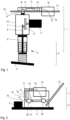
- FIG. 1 shows schematically a vibrating tamper with an upper mass 1 and a lower mass 2 movable relative to the upper mass 1.
- the upper mass 1 and the lower mass 2 are coupled to one another by a spring device 3 known per se.
- a soil contact plate 4 for soil compaction is provided on the underside of the lower mass 2 .
- a drive with an electric motor 5 is provided on the upper mass 1 , which drives a crank wheel 6 in rotation, which is coupled to a connecting rod 8 via a crank pin 7 .
- the connecting rod 8 is connected to a ramming piston 9 so that the rotational movement of the crank wheel 6 is converted into a reciprocating movement of the ramming piston 9 .
- the linear movement of the ramming piston 9 is then finally transmitted via the spring device 3 to the ground contact plate 4, which carries out the actual ramming movement.
- a rechargeable battery 10 serving as an electrical energy store is provided for supplying energy to the electric motor 5 .
- the electrical current provided by the rechargeable battery 10 is converted or converted by a converter 11 serving as a converter device with regard to its voltage and its frequency into a current suitable for the electric motor 5 .
- a converter 11 serving as a converter device with regard to its voltage and its frequency into a current suitable for the electric motor 5 .
- crank wheel 6, the crank pin 7 and the connecting rod 8 are housed in a crankcase 12 to which the electric motor 5 is also attached.
- the electric motor 5 can also be arranged largely inside the crankcase 12 .
- a handle device 13 On the upper side of the crankcase 12 is attached to the upper mass 1 a handle device 13 embodied as a handle bar.
- a vibration decoupling device 14 for example in the form of rubber buffers, is arranged between the grip device 13 and the crankcase 12 for vibration decoupling of the grip device 13 .
- the handle device 13 can be pivoted within certain limits relative to the rest of the upper mass 1, in particular relative to the crankcase 12, in order for an operator to hold the handle bar or the handle device 13 as intended on the in 1 right end to protect against exposure to excessive vibration.
- Both the rechargeable battery 10 and the converter 11 are attached to the handle device 13 or are carried by it. It is possible for the rechargeable battery 10 to be attached to the handle device 13 so that it can be changed, so that it can be replaced by a fresh rechargeable battery 10 in each case.
- a fan device 15 which has a fan, e.g. a fan, and a fan motor, is spatially arranged between the battery 10 and the converter 11.
- the fan device 15 generates a cooling air flow 16 in which it sucks in air via the battery 10 and pushes it downstream via the converter 11 until the cooling air flow 16 returns to the environment.
- the course of the cooling air flow 16 is in 1 symbolically represented by an arrow.
- the fan device 15 can also be arranged upstream of the battery 10 or downstream of the converter 11 in order to generate the cooling air flow 16 (see arrow direction) in a suitable manner.
- FIG 2 shows another embodiment of the work machine as a vibrating plate. Functionally similar or identical components to the embodiment of FIG 1 are denoted by the same reference numerals.
- the vibration plate also has an upper mass 1 and a lower mass 2 , the lower mass 2 being movable relative to the upper mass 1 .
- vibration decoupling elements 20 are provided between the upper mass 1 and the lower mass 2 .
- a ground contact plate 4 is formed on the lower mass 2 .
- the electric motor 5 which drives a vibration exciter 21 , is arranged on the ground contact plate 4 .
- the vibration exciter 21 can, for example, have one or more imbalance shafts, which are set in rotation by the electric motor 5 serving as the drive motor in order to generate the desired vibrations. The vibrations are then introduced via the soil contact plate 4 directly into the soil to be compacted.
- the battery 10 providing the energy for the electric motor 5 is arranged on the upper mass 1, together with the converter 11.
- the fan device 15 is arranged between the battery 10 and the converter 11 in order to bring about the flow of cooling air 16 through the battery 10 and along the converter 11 .
- the cooling air flow 16 can be guided downstream of the fan device 15 in such a way that the converter 11 is surrounded by the cooling air flow 16 on all sides or at least on both sides.
- the cooling effect is also sufficient if the battery 10 and/or converter 11 only has a flow from one side.
- the cover 17 is provided for improved guidance of the cooling air flow 16 .
- the handle device 13 is designed in the form of a drawbar that can be guided by an operator and is fastened to the lower mass 2 .
- FIG 3 shows a variant of the vibration plate from FIG 2 .
- the vibration plate also has an upper mass 1 and a lower mass 2 .
- the ground contact plate 4 on which the vibration exciter 21 is attached is provided on the lower mass 2 .
- the vibration exciter 21 not only has the actual exciter unit, but also integrates the electric motor 5.
- the battery 10 is provided on the upper mass 1, as well as an air duct device 30.
- the air guide device 30 is a compact unit that extends perpendicularly with a vertical component.
- the fan device 15 for generating the cooling air flow 16 is provided in the air guiding device 30 .
- the cooling air flow 16 is in 3 symbolized by several arrows of different sizes, the reference number 16 not being applied to each arrow in order not to impair the clarity of the image representation.
- the converter 11 is held in the air guiding device 30 .
- the converter 11 is arranged essentially vertically and the cooling air flow 16 flows against it on both sides.
- the air guiding device 30 penetrates the upper mass 1 downwards, so that the cooling air flow 16 can be carried out via an air outlet opening 31 .
- the cooling air flow 16 is deflected in the direction of the vibration exciter 21 and the electric motor 5, so that it can still be used there for cooling.
- the vibration exciter 21 and the electric motor 5 are mounted on the ground contact plate 4 in such a way that the cooling air flow 16 can flow around them as well as possible.
- the cooling air flow 16 can also flow underneath the electric motor 5, between the electric motor 5 and the ground contact plate 4, in order to improve the cooling effect.
- an intake opening 32 is formed on the upper side of the upper mass 1, through which cooling air can flow from the environment.
- the arrangement of the suction opening 32 on the upper side makes it possible for the cooling air to enter the upper mass 1 with as little dust and dirt as possible.
- the cooling air flow 16 is then guided along the walls of the battery 10 or through the battery 10 .
- the fan device 15 that generates the cooling air flow 16 is arranged in the upper area of the air guiding device 30 .
- An air inlet opening 33 is provided upstream of the fan device 15 and downstream of the battery 10 , via which the cooling air flow 16 can enter the air guiding device 30 after it has been transported through the fan device 15 .
- the air guiding device 30 has an arcuate design in order to sensibly guide the cooling air flow 16 along the converter device 11 .
- cooling air flow 16 is divided after exiting the air guiding device 30 via the air outlet opening 31 in order to flow around the vibration exciter 21 with the electric motor 5 .
Landscapes
- Engineering & Computer Science (AREA)
- Structural Engineering (AREA)
- Civil Engineering (AREA)
- General Engineering & Computer Science (AREA)
- Chemical & Material Sciences (AREA)
- Microelectronics & Electronic Packaging (AREA)
- Electrochemistry (AREA)
- General Chemical & Material Sciences (AREA)
- Manufacturing & Machinery (AREA)
- Chemical Kinetics & Catalysis (AREA)
- Life Sciences & Earth Sciences (AREA)
- Mining & Mineral Resources (AREA)
- Physics & Mathematics (AREA)
- Architecture (AREA)
- Thermal Sciences (AREA)
- Paleontology (AREA)
- Environmental & Geological Engineering (AREA)
- Soil Sciences (AREA)
- General Life Sciences & Earth Sciences (AREA)
- Agronomy & Crop Science (AREA)
- Automation & Control Theory (AREA)
- Combustion & Propulsion (AREA)
- Acoustics & Sound (AREA)
- Aviation & Aerospace Engineering (AREA)
- Mechanical Engineering (AREA)
- Road Paving Machines (AREA)
- Cooling, Air Intake And Gas Exhaust, And Fuel Tank Arrangements In Propulsion Units (AREA)
- Motor Or Generator Cooling System (AREA)
Abstract
Description
- Die Erfindung betrifft eine Arbeitsmaschine, insbesondere eine akkubetriebene Baumaschine mit Elektroantrieb.
- Akkubetriebene Baumaschinen weisen einen Antriebsstrang auf, mit einem Elektromotor, einem Energiespeicher (Akku) und einem Umformer. Der Umformer wandelt den Strom aus dem Energiespeicher (üblicherweise ein Gleichstrom) in einen zum Versorgen des Elektromotors geeigneten Strom, z.B. einen Wechselstrom. Die Komponenten müssen effizient gekühlt werden, damit die Baumaschine zuverlässig arbeiten kann. Dies gilt vor allem für den Akku, dessen Zellen bei übermäßiger Wärmeeinwirkung dauerhaften Schaden nehmen können, was nicht nur die Speicherkapazität, sondern auch die Lebensdauer des Akkus vermindern kann.
- Zur Kühlung von Akku und Umformer ist es bekannt, an dem als Antriebsmotor dienenden Elektromotor der Baumaschine ein Lüfterrad vorzusehen, das einen Luftstrom erzeugt. Der Luftstrom kann dann nicht nur über den Antriebsmotor, sondern auch über den Akku und den Umformer geführt werden, um eine geeignete Kühlung beim Betrieb der Baumaschine zu bewirken.
- Je nach Typ der Baumaschine ist es möglich, dass der Akku und der Umformer mit einiger Entfernung zum Elektromotor angeordnet sind. Für diesen Fall ist es notwendig, dass der Kühlluftstrom über Kühlkanäle (Luftführungskanäle) geleitet wird, damit der am Antriebsmotor durch den dort vorhandenen Lüfter erzeugte Kühlluftstrom auch auf Akku und Umformer wirkt. Je nach Länge und Gestaltung der Luftführungskanäle kann die Kühlwirkung am Akku und am Umformer nur gering sein.
- Die Kühlwirkung wird nur während des Betriebs des Antriebsmotors erreicht, weil auch nur dann das Lüfterrad angetrieben wird. In anderen Betriebssituationen besteht daher das Risiko einer zu starken Wärmeeinwirkung auf Akku oder Umformer, wenn der Antriebsmotor nicht im Betrieb ist und damit kein Kühlluftstrom erzeugt wird.
- Der Erfindung liegt die Aufgabe zugrunde, eine Arbeitsmaschine anzugeben, mit einer verbesserten Kühlung für Akku und Umformer.
- Die Aufgabe wird durch eine Arbeitsmaschine mit den Merkmalen von Anspruch 1 gelöst. Vorteilhafte Ausgestaltungen sind in den abhängigen Ansprüchen angegeben.
- Es wird eine Arbeitsmaschine angegeben, mit einer Arbeitsvorrichtung zum Bewirken einer Arbeitsbewegung und mit einem Antrieb zum Antreiben der Arbeitsvorrichtung, wobei der Antrieb einen elektrischen Arbeitsmotor, einen elektrischen Energiespeicher zum Versorgen des Antriebsmotors mit elektrischem Strom und eine Umformereinrichtung zum Umformen des Stroms aus dem Energiespeicher und Zuführen des Stroms zu dem Antriebsmotor aufweist. Dabei ist eine Kühlvorrichtung vorgesehen, zum Kühlen des Energiespeichers und der Umformereinrichtung, wobei die Kühlvorrichtung wenigstens eine Lüftereinrichtung aufweist, zum Erzeugen eines Kühlluftstroms, der über den Energiespeicher und die Umformereinrichtung führbar ist, wobei die Lüftereinrichtung einen Lüfter und einen den Lüfter antreibenden Lüftermotor aufweist, und wobei der Lüftermotor getrennt von dem Antriebsmotor des Antriebs vorgesehen ist.
- Bei der Arbeitsmaschine kann es sich z.B. um einen Vibrationsstampfer (Rüttelstampfer) oder um eine Vibrationsplatte (Rüttelplatte) zur Bodenverdichtung handeln. Dementsprechend kann die Arbeitsbewegung eine Stampfbewegung oder Rüttelbewegung sein, die in an sich bekannter, geeigneter Weise z.B. in den Boden eingelassen wird. Auch andere Baumaschinen können als derartige Arbeitsmaschinen eingesetzt werden.
- Bei dem Energiespeicher kann es sich um einen Akku bzw. eine wiederaufladbare Batterie mit an sich bekannter Bauart handeln.
- Die Umformereinrichtung kann z.B. ein Frequenzumformer sein, der geeignet ist, um die Spannung und Frequenz des aus dem Energiespeicher zugeführten Stroms umzuformen, zu einem Strom, der für den Betrieb des elektrischen Antriebsmotors (Elektromotors) geeignet ist.
- Der Lüfter kann als Ventilator oder Propeller oder andere Einrichtung ausgebildet sein, die durch den Lüftermotor angetrieben wird, um den gewünschten Kühlluftstrom zu erzeugen.
- Der Lüftermotor selbst kann ebenfalls ein Elektromotor sein. Er ist zusätzlich zum Antriebsmotor vorgesehen und kann in der Nähe oder auch entfernt vom Antriebsmotor an der Arbeitsmaschine angeordnet sein.
- Zur Führung des Kühlluftstroms können geeignete Luftführungskanäle wie Schläuche, Rohre oder auch geeignet gestaltete Gehäuseelemente vorgesehen sein.
- Dabei ist es wichtig, dass der Kühlluftstrom über den Energiespeicher und die Umformereinrichtung geführt werden kann. Insbesondere sollte der Kühlluftstrom entlang der Außenwände von Energiespeicher und Umformereinrichtung, also entlang dem Gehäuse geführt werden. Ebenso ist es aber auch möglich, dass der Kühlluftstrom durch die jeweiligen Gehäuse geführt wird, um die Wärme enthaltenden Komponenten bestmöglich zu erreichen, damit eine wirksame Kühlung erzielt werden kann.
- Es ist möglich, mehrere Lüftereinrichtungen mit mehreren Lüftern und/oder Lüftermotoren vorzusehen, um ein flexibles Kühlkonzept vorzusehen. Die Kühlvorrichtung kann über die dann die mehreren Lüfter in geeigneter Weise verfügen und die Lüfter z.B. auch individuell ansteuern.
- Eine elektrische Versorgung des Lüftermotors bzw. der gegebenenfalls mehreren Lüftermotoren kann mit Hilfe der Energie aus dem elektrischen Energiespeicher erfolgen.
- Je nach Gestaltung der Arbeitsmaschine ist es möglich, dass für den eigentlichen Antriebsmotor keine Kühlung vorgesehen ist, sondern dass die Kühlung allein für die Komponenten Energiespeicher und Umformereinrichtung erfolgt. Die Kühlung des Antriebsmotors kann dann immanent durch Konvektion oder Strahlung möglich sein.
- Der Kühlluftstrom kann zwischen dem Energiespeicher und der Umformereinrichtung geführt sein. Dabei ist es möglich, den Kühlluftstrom - je nach Gestaltung - in beide Richtungen zu führen, also entweder zunächst über den Energiespeicher und dann stromab vom Energiespeicher über die Umformereinrichtung oder in umgekehrter Richtung. Da der Energiespeicher die häufig sehr wärmesensitiven Zellen der Batterie umfasst, kann es zweckmäßig sein, die aus der Umgebung angesaugte Kühlluft zunächst über den Energiespeicher und erst danach, wenn sie schon die Wärme des Energiespeichers aufgenommen hat, über den Umformer zu führen.
- Der Lüfter kann im Kühlluftstrom zwischen dem Energiespeicher und der Umformereinrichtung angeordnet sein. Der Lüfter dient zum Erzeugen des Kühlluftstroms und bewirkt je nach Strömungsrichtung einen Saugeffekt oder einen Gebläseeffekt (Drücken der Kühlluft in Stromab-Richtung). Die Anordnung des Lüfters zwischen Energiespeicher und Umformereinrichtung ermöglicht einen besonders kompakten Aufbau. Gleichzeitig ist es möglich, den Lüfter relativ klein auszuführen, weil beide Strömungsseiten (stromauf und stromab vom Lüfter) genutzt werden, um den Kühlluftstrom zu erzeugen und die jeweils dort angeordnete Komponente zu kühlen.
- Es kann eine Lüftungssteuerungseinrichtung vorgesehen sein, um Ansteuern des Lüftermotors. Die Lüftungssteuerungseinrichtung kann den Lüftermotor insbesondere unabhängig vom eigentlichen Antriebsmotor der Arbeitsmaschine ansteuern. Insbesondere erlaubt die Steuerung ein temperaturabhängiges Ein- und Ausschalten des Lüftermotors und somit kein betriebsabhängiges Schalten des Lüftermotors in Abhängigkeit vom Ein- und Ausschalten des Antriebsmotors.
- Als maßgebliche Temperatur kann die Lüftungssteuerungseinrichtung z.B. die Temperatur in der Umgebung, am bzw. im Umformer und/oder am oder im Energiespeicher berücksichtigen. Auch ist es möglich, die Lüfterdrehzahl in Abhängigkeit von der Temperatur zu regeln, um einen unnötig starken Betrieb der Kühlvorrichtung und damit auch einen unnötigen Energieverbrauch zu vermeiden.
- Auf diese Weise kann eine bedarfsgerechte Kühlung des Energiespeichers und der Umformereinrichtung erreicht werden. Dadurch lässt sich eine frühzeitige Zellalterung in dem Energiespeicher vermeiden, wodurch die Energie- und Leistungskapazität der Zellen gesteigert werden kann.
- Die erforderliche Stromversorgung der Lüftungssteuerungseinrichtung wie auch der Lüftereinrichtung kann ebenfalls über den Energiespeicher und gegebenenfalls auch über die Umformereinrichtung bereitgestellt werden.
- Bei einer Ausführungsform der Arbeitsmaschine können eine Obermasse und eine Untermasse vorgesehen sein, wobei die Untermasse relativ zu der Obermasse bewegbar ist, wobei an der Obermasse der Energiespeicher, die Umformereinrichtung und die Kühlvorrichtung angeordnet sind, und wobei an der Untermasse eine Bodenkontaktplatte vorgesehen sein kann, zum Ausführen der Arbeitsbewegung. Diese Arbeitsmaschine kann z.B. als Stampfer oder Rüttelplatte bzw. Vibrationsplatte ausgeführt sein. Dementsprechend kann die Arbeitsvorrichtung zwischen Obermasse und Untermasse wirken und z.B. als Stampfvorrichtung oder als Schwingungserreger ausgebildet sein. Zwischen Obermasse und Untermasse kann eine Federeinrichtung bzw. eine Feder-Dämpfereinrichtung vorgesehen sein, um eine Schwingungsentkopplung zwischen Obermasse und Untermasse zu erreichen und die Relativbeweglichkeit zu ermöglichen.
- Der Antriebsmotor kann je nach Ausführungsform an der Obermasse oder an der Untermasse angeordnet sein. Bei einem Stampfer wird es sinnvoll sein, den Antriebsmotor an der Obermasse anzuordnen und die Antriebsbewegung des Antriebsmotors über eine als Arbeitsvorrichtung dienende Stampfvorrichtung auf die Untermasse mit der Bodenkontaktplatte zu übertragen.
- Dieses Prinzip ist auch bei einer Vibrationsplatte realisierbar, bei der die Antriebsbewegung des Antriebsmotors an der Obermasse dann auf den Schwingungserreger an der Untermasse übertragen werden muss.
- Bei einer Variante kann der Antriebsmotor auch direkt an der Untermasse, z.B. direkt auf der Bodenkontaktplatte angebracht sein und dort mit einem Schwingungserreger gekoppelt werden.
- Die Obermasse kann eine Griffeinrichtung aufweisen, zum Führen der Arbeitsmaschine durch einen Benutzer, wobei der Energiespeicher und die Lüftereinrichtung an der Griffeinrichtung angeordnet sein können. Bei dieser Ausführungsform kann die Arbeitsmaschine z.B. als Stampfer ausgebildet sein. Die Griffeinrichtung, z.B. ein an sich bekannter Griffbügel, kann vom Rest der Obermasse durch eine Schwingungsentkopplungseinrichtung entkoppelt sein, um den die Griffeinrichtung greifenden Benutzer vor starken Schwingungen zu schützen, so dass die auf den Benutzer einwirkenden Hand-Arm-Vibrationen unterhalb von zulässigen Grenzwerten bleiben.
- Der Energiespeicher und die Lüftereinrichtung können an der Griffeinrichtung angebracht sein bzw. von der Griffeinrichtung getragen werden. Da die Griffeinrichtung, wie oben dargelegt, schwingungsentkoppelt sein kann, werden dann auch der Energiespeicher und die Lüftereinrichtung nur geringen Schwingungen ausgesetzt, was ihre Lebensdauer erhöht bzw. keine weiteren Schwingungsentkopplungsmaßnahmen erfordert. Umgekehrt trägt die durch den Energiespeicher und den Lüfter bewirkte höhere Masse an der Griffeinrichtung auch zu einer besseren Schwingungsreduzierung am Griffbügel bei.
- Die Umformereinrichtung kann an der Griffeinrichtung angeordnet sein. Das bedeutet, dass der Umformer zusätzlich zum Energiespeicher und zum Lüfter ebenfalls von dem Griffbügel getragen werden kann.
- An der Griffeinrichtung kann eine Abdeckung vorgesehen sein, wobei der Energiespeicher und/oder die Lüftereinrichtung und/oder die Umformereinrichtung unter der Abdeckung angeordnet sein können. Die Abdeckung dient als Schutz, insbesondere für den Energiespeicher und den Umformer. Zudem können in der Abdeckung geeignete Luftführungskanäle ausgebildet sein, um die von der Lüftereinrichtung geförderte Kühlluft zu den zu kühlenden Komponenten zu führen.
- Die Arbeitsmaschine kann eine Bodenverdichtungsvorrichtung sein. Insbesondere kann die Arbeitsmaschine eine Stampfvorrichtung oder eine Vibrationsplatte zur Bodenverdichtung sein.
- Insbesondere kann die Arbeitsmaschine eine Obermasse und eine relativ zu der Obermasse bewegbare Untermasse aufweisen.
- An der Obermasse kann eine Luftführungseinrichtung vorgesehen sein, wobei der Kühlluftstrom wenigstens teilweise durch die Luftführungseinrichtung geführt wird, und wobei die Luftführungseinrichtung die Umformereinrichtung trägt.
- Die Luftführungseinrichtung hat in diesem Fall wenigstens zwei Funktionen, nämlich das Führen des Kühlluftstroms und das Tragen des Umformers. Zudem ist es optional möglich, dass die Luftführungseinrichtung auch die Lüftereinrichtung und/oder Versorgungsleitungen bzw. Elektrokabel trägt und führt, die z.B. zu der Umformereinrichtung geführt werden müssen. Die Luftführungseinrichtung kann somit als Multifunktionsteil ausgebildet sein.
- Z.B. kann die Luftführungseinrichtung als eine Einheit an der Obermasse befestigbar sein, so dass die Luftführungseinrichtung mit den von ihr getragenen Komponenten gemeinsam an der Obermasse befestigt werden kann.
- Der Kühlluftstrom kann dabei wenigstens teilweise durch die Luftführungseinrichtung geführt werden. Er kann aber auch noch in anderen Bereichen bzw. durch andere Bereiche der Arbeitsmaschine strömen.
- Zwischen der Luftführungseinrichtung und der Obermasse kann eine Schwingungsentkopplungseinrichtung vorgesehen sein. Damit kann die Luftführungseinrichtung mit der Lüftereinrichtung (sofern vorhanden) und der Umformereinrichtung schwingungsentkoppelt von der restlichen Obermasse an der Obermasse befestigt sein. Als Schwingungsentkopplungseinrichtung eignen sich z.B. Gummipuffer oder Schaumpolster.
- Der Energiespeicher kann in einer Akkuaufnahme gehalten sein, wobei die Akkuaufnahme und die Luftführungseinrichtung miteinander gekoppelt sein können, und wobei die Akkuaufnahme und die Luftführungseinrichtung gemeinsam durch die Schwingungsentkopplungseinrichtung schwingungsentkoppelt an der Obermasse befestigt sein können.
- Dabei kann der Energiespeicher in der Akkuaufnahme auswechselbar gehalten werden und z.B. durch einen frischen Energiespeicher ausgetauscht werden. Die Akkuaufnahme und die Luftführungseinrichtung können fest mechanisch miteinander verbunden sein.
- Die Luftführungseinrichtung kann eine Trägerstruktur und eine Abdeckeinrichtung aufweisen, die zu einer Einheit zusammenmontierbar sind. Dabei kann die Trägerstruktur ausgebildet sein zum Tragen der Lüftereinrichtung und der Umformereinrichtung, wobei die Trägerstruktur und die Abdeckeinrichtung im zusammengebauten Zustand einen Luftkanal bilden, der sich wenigstens zwischen der Lüftereinrichtung und der Umformereinrichtung erstreckt. Der Luftkanal kann dementsprechend zum Führen des Kühlluftstroms genutzt werden. Die Luftführungseinrichtung kann somit zwei Komponenten aufweisen, die zu einer Einheit zusammengebaut werden und auch als Gehäusekomponenten für den Luftkanal dienen können.
- Die Trägerstruktur kann zusammen mit der Luftführungseinrichtung und der Umformereinrichtung als eine Einheit an der Obermasse befestigbar sein. Somit ist es möglich, die Lüftereinrichtung und die Umformereinrichtung auf der Trägerstruktur zu montieren und dann die Trägerstruktur an der Obermasse zu befestigen. Dies kann auch mit bereits aufgesetzter und montierter Abdeckeinrichtung erfolgen.
- Die Luftführungseinrichtung kann eine stromauf von der Lüftereinrichtung vorgesehene Lufteintrittsöffnung aufweisen, die stromab von dem Energiespeicher angeordnet ist. Über die Lufteintrittsöffnung kann dann im Betrieb durch die Lüftereinrichtung Luft angesaugt werden, die vorher durch den Energiespeicher strömt und diesen dabei kühlt. Selbstverständlich ist es auch in diesem Fall möglich, dass der Kühlluftstrom durch den Energiespeicher hindurch oder an Gehäusewänden des Energiespeichers entlang geführt wird.
- Die Luftführungseinrichtung kann eine stromab von der Umformereinrichtung vorgesehene, nach unten gerichtete Luftaustrittsöffnung aufweisen. Dabei kann die nach unten gerichtete Luftaustrittsöffnung auch schräg nach unten gerichtet sein, so dass der dort austretende Luftstrom gezielt an weitere Stellen geführt werden kann. Insbesondere kann der an der Luftaustrittsöffnung austretende Kühlluftstrom zu weiteren Komponenten der Arbeitsmaschine geführt werden, wie z.B. zu einem Schwingungserreger oder einem Elektroantrieb des Schwingungserregers, wie später noch erläutert wird.
- In der Obermasse kann eine Öffnung vorgesehen sein, durch die sich die Luftführungseinrichtung nach unten in Richtung der Untermasse erstreckt. Auf diese Weise können die Voraussetzungen geschaffen werden, dass über die Luftführungseinrichtung ein Kühlluftstrom auch zu Komponenten an der Untermasse geführt wird.
- Dieser Aufbau eignet sich besonders für eine als Rüttelplatte bzw. Vibrationsplatte ausgeführte Arbeitsmaschine.
- Dabei kann die Untermasse einen auf der Bodenkontaktplatte angeordneten Schwingungserreger aufweisen, zum Erzeugen von Schwingungen, die durch die Bodenkontaktplatte zur Bodenverdichtung nutzbar sind, wobei der Kühlluftstrom über die Luftaustrittsöffnung austreten und in Richtung des an der Untermasse vorgesehenen Schwingungserregers geführt werden kann.
- Die Luftführungseinrichtung kann dabei stromab von der Umformereinrichtung einen Luftkanalabschnitt aufweisen, zum Führen des Kühlluftstroms in Richtung des Schwingungserregers, um diesen zu kühlen. Insbesondere kann dabei eine Strömungsrichtung für den Kühlluftstrom in Richtung eines den Schwingungserreger antreibenden Antriebsmotors, z.B. eines Hydraulikmotors oder Elektromotors, erzeugt werden.
- Ein typischer Schwingungserreger weist dabei die eigentliche Erregereinrichtung, z.B. mit einer oder mehreren jeweils eine Unwuchtmasse tragenden Unwuchtwellen, sowie einen Antriebsmotor für die Erregereinrichtung auf.
- Zunehmend ist es möglich, dass die Unwuchtwelle bzw. die Unwuchtwellen in der Erregereinrichtung direkt durch einen Elektromotor angetrieben werden. Der Elektromotor kann in geeigneter Weise, z.B. auf Anschraubdomen schwebend, auf der Bodenkontaktplatte angebracht werden, so dass er an mehreren Seiten, insbesondere auch an seiner Unterseite, von dem über die Luftführungseinrichtung zugeführten Kühlluftstrom gekühlt werden kann. Dabei ist es anzustreben, dass der Elektromotor bestmöglich gekühlt wird und dass, sofern technisch möglich, der Kühlluftstrom auch durch das Innere des Motors bzw. dessen Motorwicklung geführt wird. Die Kontur der Erregereinrichtung bzw. des Motorgehäuses des Elektromotors kann dabei so geformt sein, dass sich dort eine bestmögliche Luftführung über das Motorgehäuse bzw. über die Erregereinrichtung ergibt.
- Die Kühlvorrichtung kann wenigstens zwei Lüftereinrichtungen aufweisen, wobei die von den beiden Lüftereinrichtungen erzeugten Luftströme zu einem gemeinsamen Kühlluftstrom zusammenführbar sind. Dabei können die Lüftereinrichtungen parallel zueinander angeordnet sein und jeweils Einzel-Luftströme erzeugen, die dann über die Luftführungseinrichtung zu einem gemeinsamen Kühlluftstrom zusammengeführt werden.
- Diese Variante ermöglicht es, die Lüftereinrichtungen relativ kompakt und klein aufzubauen und doch in Summe einen wirkungsvollen Kühlluftstrom zu erzeugen.
- Stromauf von dem Energiespeicher kann an einer Oberseite der Obermasse eine Ansaugöffnung für den Kühlluftstrom vorgesehen sein. Die Ansaugöffnung kann dabei im Wesentlichen vertikal nach oben gerichtet sein. Die Oberseite der Obermasse wird im Betrieb der Rüttelplatte relativ gut vor Staub und Schmutz geschützt sein, so dass über die dort vorgesehene Ansaugöffnung vergleichsweise wenig Staub in die Luftführungseinrichtung gezogen wird. Die Ansaugöffnung kann durch Gitter oder Umlenklamellen zusätzlich geschützt werden, um das Eindringen von Staub zu verringern.
- Somit wird eine Arbeitsmaschine angegeben, bei der frische Umgebungsluft an einer Stelle angesaugt wird, an der am wenigsten Staub in der Luft zu erwarten ist. Diese Luft wird dann als Kühlluftstrom in den Energiespeicher (Akku) gezogen und durch die Lüftereinrichtung (oder die mehreren Lüftereinrichtungen) in der Luftführungseinrichtung auf die Umformereinrichtung geblasen. Der Querschnitt der luftführenden Kanäle in der Luftführungseinrichtung verändert sich dabei so, dass die Umformereinrichtung eine optimale Kühlwirkung erfährt.
- Unterhalb von der Obermasse kann sich die Luftaustrittsöffnung der Luftführungseinrichtung befinden. Dort kann die Luft direkt auf den Schwingungserreger mit dem dort verbauten Motor geleitet werden, um auch hier eine möglichst optimale Kühlung zu erreichen.
- Die vorgesehene Kühlvorrichtung kühlt auf diese Weise alle in der Arbeitsmaschine vorhandenen Komponenten, die eine nennenswerte Verlustleistung im Betrieb erzeugen. Dabei ist die Reihenfolge der Kühlung, also der Verlauf des Kühlluftstroms, so gewählt, dass zunächst die Komponente gekühlt wird, die die niedrigste zulässige Temperatur aufweist (z.B. der Energiespeicher). Die letzte Komponente im Kühlluftstrom hingegen kann die höchste zulässige Temperatur ertragen (z.B. der Elektromotor im Schwingungserreger). Gleichzeitig wird die Luft so geleitet, dass sie bei einer maximal zulässigen Umgebungstemperatur von z.B. 45° die Verlustleistung der jeweiligen Komponente, an der sie vorbeigeführt wird, präzise ableiten kann. Diese ausgeglichene und optimierte Kühlleistung ermöglicht es, besonders schwache Lüfter zu verwenden, die ihrerseits nur geringe Leistungsanforderungen stellen, die im Betrieb aus dem Energiespeicher befriedigt werden müssen.
- Mithilfe der Erfindung ist es möglich, das Thermomanagement bei einer Arbeitsmaschine zu verbessern, um ein Überhitzen des Akkus und auch des Umformers zu vermeiden und somit für eine Schonung und eine Verlängerung der Lebensdauer des Akkus zu sorgen.
- Durch die Nutzung von Lüftern, z.B. montiert am Griffbügel vor oder unterhalb des Umformers, kann der kühlende Luftstrom zunächst über den Akku angesaugt und danach über den Umformer geführt werden. Die Ansteuerung des Lüfters unabhängig vom Betriebszustand des Antriebsmotors kann den Einsatz auch in warmen Umgebungen, z.B. bei starker Sonneneinstrahlung, ermöglichen.
- Diese und weitere Vorteile und Merkmale der Erfindung werden nachfolgend anhand von Beispielen unter Zuhilfenahme der begleitenden Figuren näher erläutert. Es zeigen:
- Fig. 1
- in schematischer seitlicher Schnittdarstellung eine erfindungsgemäße Arbeitsmaschine als Rüttelstampfer;
- Fig. 2
- in schematischer Seitenansicht eine andere erfindungsgemäße Arbeitsmaschine als Vibrationsplatte;
- Fig. 3
- eine Variante zu einer Vibrationsplatte mit Luftführungseinrichtung; und
- Fig. 4
- ein Detail zu der Variante von
Fig. 3 . -
Fig. 1 zeigt schematisch einen Rüttel- bzw. Vibrationsstampfer, mit einer Obermasse 1 und einer relativ zu der Obermasse 1 bewegliche Untermasse 2. Die Obermasse 1 und die Untermasse 2 sind durch eine an sich bekannte Federeinrichtung 3 miteinander gekoppelt. An der Unterseite der Untermasse 2 ist eine Bodenkontaktplatte 4 zur Bodenverdichtung vorgesehen. - An der Obermasse 1 ist ein Antrieb mit einem Elektromotor 5 vorgesehen, der ein Kurbelrad 6 drehend antreibt, das über einen Kurbelzapfen 7 mit einem Pleuel 8 gekoppelt ist. Das Pleuel 8 ist mit einem Stampfkolben 9 verbunden, so dass die Drehbewegung des Kurbelrads 6 in eine Hin- und Herbewegung des Stampfkolbens 9 gewandelt wird. Die lineare Bewegung des Stampfkolbens 9 wird dann schließlich über die Federeinrichtung 3 auf die Bodenkontaktplatte 4 übertragen, die die eigentliche Stampfbewegung ausführt.
- Zur Energieversorgung des Elektromotors 5 ist ein als elektrischer Energiespeicher dienender Akku 10 vorgesehen.
- Der vom Akku 10 bereitgestellte elektrische Strom wird von einem als Umformereinrichtung dienenden Umformer 11 hinsichtlich seiner Spannung und seiner Frequenz in einem für den Elektromotor 5 geeignete Strom gewandelt bzw. umgeformt. Insbesondere kann es dabei möglich sein, aus dem im Akku 10 gespeicherten Gleichstrom einen Wechselstrom für den Elektromotor 5 zu erzeugen.
- Das Kurbelrad 6, der Kurbelzapfen 7 und das Pleuel 8 sind in einem Kurbelgehäuse 12 untergebracht, an dem auch der Elektromotor 5 befestigt ist. Bei einer Variante kann der Elektromotor 5 auch weitgehend im Inneren des Kurbelgehäuses 12 angeordnet sein.
- An der Oberseite des Kurbelgehäuses 12 ist eine zu der Obermasse 1 gehörende, als Griffbügel ausgebildete Griffeinrichtung 13 angebracht. Zur Schwingungsentkopplung der Griffeinrichtung 13 ist zwischen der Griffeinrichtung 13 und dem Kurbelgehäuse 12 eine Schwingungsentkopplungseinrichtung 14, z.B. in Form von Gummipuffern, angeordnet. Dadurch ist die Griffeinrichtung 13 in gewissen Grenzen relativ zu der restlichen Obermasse 1, insbesondere relativ zum Kurbelgehäuse 12 verschwenkbar, um einen Bediener, der den Griffbügel bzw. die Griffeinrichtung 13 bestimmungsgemäß am in
Fig. 1 rechten Ende greift, vor der Einwirkung übermäßig starker Schwingungen zu schützen. - Sowohl der Akku 10 als auch der Umformer 11 sind an der Griffeinrichtung 13 befestigt bzw. werden von dieser getragen. Dabei ist es möglich, dass der Akku 10 wechselbar an der Griffeinrichtung 13 befestigt ist, so dass er jeweils durch einen frischen Akku 10 ersetzt werden kann.
- Räumlich zwischen dem Akku 10 und dem Umformer 11 ist eine Lüftereinrichtung 15 angeordnet, die einen Lüfter, z.B. einen Ventilator, und einen Lüftermotor aufweist.
- Die Lüftereinrichtung 15 erzeugt einen Kühlluftstrom 16, in dem sie Luft über den Akku 10 einsaugt und stromab über den Umformer 11 drückt, bis der Kühlluftstrom 16 wieder in die Umgebung gelangt. Der Verlauf des Kühlluftstroms 16 ist in
Fig. 1 symbolhaft durch einen Pfeil dargestellt. - Zur besseren Führung des Kühlluftstroms 16 sowie zum Schutz der verschiedenen Komponenten ist eine Abdeckung 17, z.B. eine Kunststoffhaube, vorgesehen.
- Bei einer nicht dargestellten Variante kann die Lüftereinrichtung 15 auch stromauf von dem Akku 10 oder stromab von dem Umformer 11 angeordnet sein, um den Kühlluftstrom 16 (vgl. Pfeilrichtung) in geeigneter Weise zu erzeugen.
-
Fig. 2 zeigt eine andere Ausführungsform der Arbeitsmaschine als Vibrationsplatte. Funktional ähnliche oder identische Komponenten wie bei der Ausführungsform vonFig. 1 werden mit gleichen Bezugszeichen bezeichnet. - Demgemäß weist die Vibrationsplatte ebenfalls eine Obermasse 1 und eine Untermasse 2 auf, wobei die Untermasse 2 relativ zu der Obermasse 1 beweglich ist. Dazu sind Schwingungsentkopplungselemente 20 zwischen der Obermasse 1 und der Untermasse 2 vorgesehen.
- An der Untermasse 2 ist eine Bodenkontaktplatte 4 ausgebildet. Auf der Bodenkontaktplatte 4 ist der Elektromotor 5 angeordnet, der einen Schwingungserreger 21 antreibt. Der Schwingungserreger 21 kann z.B. eine oder mehrere Unwuchtwellen aufweisen, die durch den als Antriebsmotor dienenden Elektromotor 5 in Rotation versetzt werden, um die gewünschten Schwingungen zu erzeugen. Die Schwingungen werden dann über die Bodenkontaktplatte 4 direkt in den zu verdichtenden Boden eingeleitet.
- Der die Energie für den Elektromotor 5 bereitstellende Akku 10 ist an der Obermasse 1 angeordnet, zusammen mit dem Umformer 11.
- Wie bei der Ausführungsform von
Fig. 1 ist zwischen dem Akku 10 und dem Umformer 11 die Lüftereinrichtung 15 angeordnet, um den Kühlluftstrom 16 durch den Akku 10 und entlang dem Umformer 11 zu bewirken. Wie erkennbar, kann der Kühlluftstrom 16 stromab von der Lüftereinrichtung 15 derart geführt, dass der Umformer 11 möglichst allseitig bzw. wenigstens beidseitig von Kühlluftstrom 16 umströmt wird. Je nach Ausgestaltung genügt aber auch die Kühlwirkung, wenn der Akku 10 und/oder Umformer 11 nur einseitig beströmt werden. - Zur verbesserten Führung des Kühlluftstroms 16 ist die Abdeckung 17 vorgesehen.
- Die Griffeinrichtung 13 ist bei der Vibrationsplatte in Form einer durch einen Bediener führbaren Deichsel ausgebildet, die an der Untermasse 2 befestigt ist.
-
Fig. 3 zeigt in schematischer Seitenansicht eine Variante zu der Vibrationsplatte vonFig. 2 . - Die Vibrationsplatte weist ebenfalls eine Obermasse 1 und eine Untermasse 2 auf. An der Untermasse 2 ist die Bodenkontaktplatte 4 vorgesehen, auf der der Schwingungserreger 21 angebracht ist. Der Schwingungserreger 21 weist nicht nur die eigentliche Erregereinheit auf, sondern auch integriert den Elektromotor 5.
- An der Obermasse 1 ist der Akku 10 vorgesehen, sowie eine Luftführungseinrichtung 30.
- Die Luftführungseinrichtung 30 ist eine kompakte Einheit, die sich mit einer vertikalen Komponente senkrecht erstreckt. In der Luftführungseinrichtung 30 ist die Lüftereinrichtung 15 zum Erzeugen des Kühlluftstroms 16 vorgesehen. Der Kühlluftstrom 16 ist in
Fig. 3 durch mehrere unterschiedlich große Pfeile symbolisiert, wobei das Bezugszeichen 16 nicht an jedem Pfeil angetragen ist, um die Klarheit der Bilddarstellung nicht zu beeinträchtigen. - Weiterhin ist in der Luftführungseinrichtung 30 der Umformer 11 gehalten. Der Umformer 11 ist im Wesentlichen senkrecht angeordnet und wird beidseitig durch den Kühlluftstrom 16 angeströmt.
- An ihrem unteren Ende durchstößt die Luftführungseinrichtung 30 die Obermasse 1 nach unten, so dass der Kühlluftstrom 16 über eine Luftaustrittsöffnung 31 ausgeführt werden kann.
- Wie in
Fig. 3 erkennbar, wird dabei der Kühlluftstrom 16 in Richtung des Schwingungserregers 21 und des Elektromotors 5 umgelenkt, so dass er dort noch zur Kühlung genutzt werden kann. - Der Schwingungserreger 21 bzw. der Elektromotor 5 sind auf der Bodenkontaktplatte 4 derart montiert, dass sie möglichst gut durch den Kühlluftstrom 16 umströmt werden können. Insbesondere kann vorgesehen sein, dass der Kühlluftstrom 16 auch unterhalb des Elektromotors 5, zwischen Elektromotor 5 und Bodenkontaktplatte 4 strömen kann, um die Kühlwirkung zu verbessern.
- Am stromauf liegenden Ende ist an der Oberseite der Obermasse 1 eine Ansaugöffnung 32 ausgebildet, über die Kühlluft aus der Umgebung zuströmen kann. Die Anordnung der Ansaugöffnung 32 an der Oberseite ermöglicht es, dass die Kühlluft möglichst staub- und schmutzfrei in die Obermasse 1 eintritt.
- Der Kühlluftstrom 16 wird nachfolgend an den Wänden des Akkus 10 bzw. durch den Akku 10 hindurchgeführt.
- Die den Kühlluftstrom 16 erzeugende Lüftereinrichtung 15 ist im oberen Bereich der Luftführungseinrichtung 30 angeordnet. Stromauf von der Lüftereinrichtung 15 und stromab von dem Akku 10 ist eine Lufteintrittsöffnung 33 vorgesehen, über die der Kühlluftstrom 16 in die Luftführungseinrichtung 30 eintreten kann, nachdem er durch die Lüftereinrichtung 15 transportiert wurde.
-
Fig. 4 zeigt den Zusammenhang vonFig. 3 in vergrößerter, reduzierter Darstellung. - Hierbei ist die Luftführungseinrichtung 30 bogenartig ausgebildet, um den Kühlluftstrom 16 sinnvoll entlang der Umformereinrichtung 11 entlangzuführen.
- Auch hier ist erkennbar, wie der Kühlluftstrom 16 nach Austritt aus der Luftführungseinrichtung 30 über die Luftaustrittsöffnung 31 aufgeteilt wird, um den Schwingungserreger 21 mit dem Elektromotor 5 zu umströmen.
Claims (15)
- Arbeitsmaschine, mit- einer Arbeitsvorrichtung zum Bewirken einer Arbeitsbewegung; und mit- einem Antrieb zum Antreiben der Arbeitsvorrichtung;
wobei- der Antrieb einen elektrischen Antriebsmotor (5), einen elektrischen Energiespeicher (10) zum Versorgen des Antriebsmotors (5) mit elektrischem Strom und eine Umformereinrichtung (11) zum Umformen des Stroms aus dem Energiespeicher (10) und Zuführen des Stroms zu dem Antriebsmotor (5) aufweist;- eine Kühlvorrichtung vorgesehen ist, zum Kühlen des Energiespeichers (10) und der Umformereinrichtung (11);- die Kühlvorrichtung wenigstens eine Lüftereinrichtung (15) aufweist, zum Erzeugen eines Kühlluftstroms (16), der über den Energiespeicher (10) und die Umformereinrichtung (11) führbar ist;- die Lüftereinrichtung (15) einen Lüfter und einen den Lüfter antreibenden Lüftermotor aufweist; und wobei- der Lüftermotor getrennt von dem Antriebsmotor (5) des Antriebs vorgesehen ist. - Arbeitsmaschine nach Anspruch 1, wobei der Kühlluftstrom (16) zwischen dem Energiespeicher (10) und der Umformereinrichtung (11) geführt ist.
- Arbeitsmaschine nach einem der vorstehenden Ansprüche, wobei der Lüfter im Kühlluftstrom (16) zwischen dem Energiespeicher (10) und der Umformereinrichtung (11) angeordnet ist.
- Arbeitsmaschine nach einem der vorstehenden Ansprüche, wobei- eine Obermasse (1) und eine Untermasse (2) vorgesehen sind;- die Untermasse (2) relativ zu der Obermasse (1) bewegbar ist;- an der Obermasse (1) der Energiespeicher (10), die Umformereinrichtung (11) und die Kühlvorrichtung angeordnet sind; und wobei- an der Untermasse (2) eine Bodenkontaktplatte (4) vorgesehen ist, zum Ausführen der Arbeitsbewegung.
- Arbeitsmaschine nach einem der vorstehenden Ansprüche wobei- an der Obermasse (1) eine Luftführungseinrichtung (30) vorgesehen ist;- der Kühlluftstrom (16) wenigstens teilweise durch die Luftführungseinrichtung (30) geführt wird; und wobei- die Luftführungseinrichtung (30) die Umformereinrichtung (11) trägt.
- Arbeitsmaschine nach einem der vorstehenden Ansprüche wobei zwischen der Luftführungseinrichtung (30) und der restlichen Obermasse (1) eine Schwingungsentkopplungseinrichtung vorgesehen ist.
- Arbeitsmaschine nach einem der vorstehenden Ansprüche wobei- der Energiespeicher (10) in einer Akkuaufnahme gehalten ist;- die Akkuaufnahme und die Luftführungseinrichtung (30) miteinander gekoppelt sind; und wobei- die Akkuaufnahme und die Luftführungseinrichtung (30) gemeinsam durch die Schwingungsentkopplungseinrichtung schwingungsentkoppelt an der Obermasse (1) befestigt sind.
- Arbeitsmaschine nach einem der vorstehenden Ansprüche wobei- die Luftführungseinrichtung (30) eine Trägerstruktur und eine Abdeckeinrichtung aufweist, die zu einer Einheit zusammen montierbar sind;- die Trägerstruktur ausgebildet ist zum Tragen der Lüftereinrichtung (15) und der Umformereinrichtung (11); und wobei- die Trägerstruktur und die Abdeckeinrichtung im zusammengebauten Zustand einen Luftkanal bilden, der sich wenigstens zwischen der Lüftereinrichtung (15) und der Umformereinrichtung (11) erstreckt.
- Arbeitsmaschine nach einem der vorstehenden Ansprüche wobei die Trägerstruktur zusammen mit der Lüftereinrichtung (15) und der Umformereinrichtung (11) als eine Einheit an der Obermasse (1) befestigbar ist.
- Arbeitsmaschine nach einem der vorstehenden Ansprüche wobei die Luftführungseinrichtung (30) eine stromauf von der Lüftereinrichtung (15) vorgesehene Lufteintrittsöffnung (33) aufweist, die stromab von dem Energiespeicher (10) anordenbar ist.
- Arbeitsmaschine nach einem der vorstehenden Ansprüche wobei die Luftführungseinrichtung (30) eine stromab von der Umformereinrichtung (11) vorgesehene, nach unten gerichtete Luftaustrittsöffnung (31) aufweist.
- Arbeitsmaschine nach einem der vorstehenden Ansprüche wobei in der Obermasse (1) eine Öffnung vorgesehen ist, durch die sich die Luftführungseinrichtung (30) nach unten in Richtung der Untermasse (2) erstreckt.
- Arbeitsmaschine nach einem der vorstehenden Ansprüche wobei- die Untermasse (2) einen auf der Bodenkontaktplatte (4) angeordneten Schwingungserreger (21) aufweist, zum Erzeugen von Schwingungen, die durch die Bodenkontaktplatte (4) zur Bodenverdichtung nutzbar sind; und wobei- der Kühlluftstrom (16) über die Luftaustrittsöffnung (31) austritt und in Richtung des an der Untermasse (2) vorgesehen Schwingungserregers (21) geführt wird.
- Arbeitsmaschine nach einem der vorstehenden Ansprüche wobei- die Kühlvorrichtung wenigstens zwei Lüftereinrichtungen (15) aufweist; und wobei- die von den beiden Lüftereinrichtungen (15) erzeugten Luftströme zu einem gemeinsamen Kühlluftstrom (16) zusammenführbar sind.
- Arbeitsmaschine nach einem der vorstehenden Ansprüche wobei stromauf von dem Energiespeicher (15) an einer Oberseite der Obermasse (1) eine Ansaugöffnung (32) für den Kühlluftstrom (16) vorgesehen ist.
Priority Applications (2)
| Application Number | Priority Date | Filing Date | Title |
|---|---|---|---|
| US17/976,017 US20230138832A1 (en) | 2021-10-29 | 2022-10-28 | Electrical Work Machine Having a Cooled Battery |
| CN202211333907.0A CN116065558A (zh) | 2021-10-29 | 2022-10-28 | 具有蓄电池冷却的电动作业机械 |
Applications Claiming Priority (1)
| Application Number | Priority Date | Filing Date | Title |
|---|---|---|---|
| DE102021128350.7A DE102021128350A1 (de) | 2021-10-29 | 2021-10-29 | Elektrische Arbeitsmaschine mit Akkukühlung |
Publications (2)
| Publication Number | Publication Date |
|---|---|
| EP4174233A1 true EP4174233A1 (de) | 2023-05-03 |
| EP4174233B1 EP4174233B1 (de) | 2025-09-17 |
Family
ID=81850102
Family Applications (2)
| Application Number | Title | Priority Date | Filing Date |
|---|---|---|---|
| EP22175425.2A Active EP4174233B1 (de) | 2021-10-29 | 2022-05-25 | Elektrische arbeitsmaschine mit akkukühlung |
| EP22203541.2A Active EP4174235B1 (de) | 2021-10-29 | 2022-10-25 | Elektrische arbeitsmaschine mit akkukühlung |
Family Applications After (1)
| Application Number | Title | Priority Date | Filing Date |
|---|---|---|---|
| EP22203541.2A Active EP4174235B1 (de) | 2021-10-29 | 2022-10-25 | Elektrische arbeitsmaschine mit akkukühlung |
Country Status (6)
| Country | Link |
|---|---|
| US (1) | US20230138832A1 (de) |
| EP (2) | EP4174233B1 (de) |
| CN (1) | CN116065558A (de) |
| DE (1) | DE102021128350A1 (de) |
| ES (1) | ES3052872T3 (de) |
| PL (1) | PL4174233T3 (de) |
Cited By (2)
| Publication number | Priority date | Publication date | Assignee | Title |
|---|---|---|---|---|
| DE102024110643A1 (de) * | 2023-09-23 | 2025-03-27 | Bomag Gmbh | Bodenverdichtungsmaschine, insbesondere Vibrationsstampfer oder Rüttelplatte, mit einem Dichtelement, Dichtelement, insbesondere für eine Kühlluftführung eines Energiespeichermoduls einer Bodenverdichtungsmaschine, und Schutzabdeckung mit einem Dichtelement |
| EP4538460A3 (de) * | 2023-09-23 | 2025-06-18 | BOMAG GmbH | Bodenverdichtungsmaschine, insbesondere vibrationsstampfer oder rüttelplatte, mit einem dichtelement, dichtelement, insbesondere für eine kühlluftführung eines energiespeichermoduls einer bodenverdichtungsmaschine, und schutzabdeckung mit einem dichtelement |
Families Citing this family (2)
| Publication number | Priority date | Publication date | Assignee | Title |
|---|---|---|---|---|
| DE102021129422A1 (de) * | 2021-11-11 | 2023-05-11 | Wacker Neuson Produktion GmbH & Co. KG | Bodenverdichtungsvorrichtung mit Elektroantrieb |
| DE102024109974A1 (de) | 2024-04-10 | 2025-10-16 | Wacker Neuson Produktion GmbH & Co. KG | Bodenverdichtungsvorrichtung mit durch einen Elektromotor angetriebenem Unwuchterreger |
Citations (6)
| Publication number | Priority date | Publication date | Assignee | Title |
|---|---|---|---|---|
| DE102011115008A1 (de) | 2011-10-06 | 2013-04-11 | Wacker Neuson Produktion GmbH & Co. KG | Elektrowerkzeug mit Schutzhaube |
| EP2584100A1 (de) * | 2010-06-15 | 2013-04-24 | Hitachi Construction Machinery Co., Ltd. | Elektrische baumaschine |
| EP2857587A1 (de) | 2010-12-22 | 2015-04-08 | Wacker Neuson Produktion GmbH & Co. KG | Bodenverdichtungsvorrichtung mit luftgekühltem Akku |
| DE102014105123A1 (de) | 2014-04-10 | 2015-10-15 | Conti Temic Microelectronic Gmbh | Batteriesystem und Verfahren zum Betreiben eines Batteriesystems |
| DE102020102949A1 (de) | 2020-02-05 | 2021-08-05 | Wacker Neuson Produktion GmbH & Co. KG | Vibrationsplatte mit Elektroantrieb |
| WO2021173951A1 (en) * | 2020-02-27 | 2021-09-02 | Cnh Industrial America Llc | An electric work vehicle having an electric drivetrain and storage component configuration |
Family Cites Families (2)
| Publication number | Priority date | Publication date | Assignee | Title |
|---|---|---|---|---|
| DE102009004443B4 (de) * | 2009-01-13 | 2010-10-21 | Wacker Neuson Se | Bodenverdichtungsvorrichtung mit in einer Fliehkraftkupplung integriertem Elektromotor |
| DE102011104269A1 (de) | 2011-06-15 | 2012-12-20 | Wacker Neuson Produktion GmbH & Co. KG | Führungsdeichsel mit Energiespeicher |
-
2021
- 2021-10-29 DE DE102021128350.7A patent/DE102021128350A1/de active Pending
-
2022
- 2022-05-25 PL PL22175425.2T patent/PL4174233T3/pl unknown
- 2022-05-25 EP EP22175425.2A patent/EP4174233B1/de active Active
- 2022-10-25 EP EP22203541.2A patent/EP4174235B1/de active Active
- 2022-10-25 ES ES22203541T patent/ES3052872T3/es active Active
- 2022-10-28 US US17/976,017 patent/US20230138832A1/en active Pending
- 2022-10-28 CN CN202211333907.0A patent/CN116065558A/zh active Pending
Patent Citations (7)
| Publication number | Priority date | Publication date | Assignee | Title |
|---|---|---|---|---|
| EP2584100A1 (de) * | 2010-06-15 | 2013-04-24 | Hitachi Construction Machinery Co., Ltd. | Elektrische baumaschine |
| EP2857587A1 (de) | 2010-12-22 | 2015-04-08 | Wacker Neuson Produktion GmbH & Co. KG | Bodenverdichtungsvorrichtung mit luftgekühltem Akku |
| EP2857587B1 (de) * | 2010-12-22 | 2018-04-25 | Wacker Neuson Produktion GmbH & Co. KG | Bodenverdichtungsvorrichtung mit luftgekühltem Akku |
| DE102011115008A1 (de) | 2011-10-06 | 2013-04-11 | Wacker Neuson Produktion GmbH & Co. KG | Elektrowerkzeug mit Schutzhaube |
| DE102014105123A1 (de) | 2014-04-10 | 2015-10-15 | Conti Temic Microelectronic Gmbh | Batteriesystem und Verfahren zum Betreiben eines Batteriesystems |
| DE102020102949A1 (de) | 2020-02-05 | 2021-08-05 | Wacker Neuson Produktion GmbH & Co. KG | Vibrationsplatte mit Elektroantrieb |
| WO2021173951A1 (en) * | 2020-02-27 | 2021-09-02 | Cnh Industrial America Llc | An electric work vehicle having an electric drivetrain and storage component configuration |
Cited By (2)
| Publication number | Priority date | Publication date | Assignee | Title |
|---|---|---|---|---|
| DE102024110643A1 (de) * | 2023-09-23 | 2025-03-27 | Bomag Gmbh | Bodenverdichtungsmaschine, insbesondere Vibrationsstampfer oder Rüttelplatte, mit einem Dichtelement, Dichtelement, insbesondere für eine Kühlluftführung eines Energiespeichermoduls einer Bodenverdichtungsmaschine, und Schutzabdeckung mit einem Dichtelement |
| EP4538460A3 (de) * | 2023-09-23 | 2025-06-18 | BOMAG GmbH | Bodenverdichtungsmaschine, insbesondere vibrationsstampfer oder rüttelplatte, mit einem dichtelement, dichtelement, insbesondere für eine kühlluftführung eines energiespeichermoduls einer bodenverdichtungsmaschine, und schutzabdeckung mit einem dichtelement |
Also Published As
| Publication number | Publication date |
|---|---|
| CN116065558A (zh) | 2023-05-05 |
| EP4174235B1 (de) | 2025-09-17 |
| ES3052872T3 (en) | 2026-01-15 |
| EP4174233B1 (de) | 2025-09-17 |
| PL4174233T3 (pl) | 2026-01-26 |
| EP4174235A1 (de) | 2023-05-03 |
| DE102021128350A1 (de) | 2023-05-04 |
| US20230138832A1 (en) | 2023-05-04 |
Similar Documents
| Publication | Publication Date | Title |
|---|---|---|
| EP4174233A1 (de) | Elektrische arbeitsmaschine mit akkukühlung | |
| EP2721217B1 (de) | Bodenverdichtungsgerät | |
| EP2655746B1 (de) | Bodenverdichtungsvorrichtung mit luftgekühltem akku | |
| DE4238564C2 (de) | Elektrowerkzeug | |
| EP2764161B1 (de) | Elektrowerkzeug mit schutzhaube | |
| DE102010014649B4 (de) | Selbstfahrender Oberflächenfräser mit elektrischem Fräswalzenantrieb | |
| EP3768893B1 (de) | Schwingstopfmaschine zum verdichten eines schotterbetts eines gleises | |
| EP2683873A2 (de) | Bodenverdichter | |
| DE102008055592A1 (de) | Verfahren und Systeme zur Wartung einer Maschine vor Ort | |
| EP2804987B1 (de) | Stampfer | |
| DE102005036560A1 (de) | Bohr- und/oder Schlaghammer mit Linearantrieb und Luftkühlung | |
| EP3910720A1 (de) | Energieversorgungsvorrichtung mit kühlvorrichtung sowie baumaschine mit einer solchen energieversorgungsvorrichtung | |
| DE102021108113B4 (de) | Selbstfahrende Bodenbearbeitungsmaschine mit kombinierter Wärmetauscher-Kühlung und Motorraumentlüftung | |
| DE102021126363A1 (de) | Bodenbearbeitungsmaschine | |
| DE102012221068A1 (de) | Anbaumodul für eine Werkzeugmaschine | |
| DE102015105445A1 (de) | Pumpsystem mit einem Kühlluft-Auslass an einer Gehäuse-Bodenseite | |
| EP1968772A1 (de) | Handgeführtes elektrowerkzeug | |
| EP2523780B1 (de) | Bohr- und/oder schlaghammer mit kühlung von gerätekomponenten | |
| DE102004018588B4 (de) | Arbeitsmaschine mit Eigenantrieb zum Hinterhergehen | |
| EP3744898A1 (de) | Bestimmungsgemäss wechselbares bodenbearbeitungsmaschinen-fräsaggregat mit kühlerlüfter zur kühlung eines geschlossenen betriebsmittelkreislaufs | |
| DE102007034013A1 (de) | Arbeitsmaschine für einen Innenrüttler | |
| EP4180579B1 (de) | Bodenverdichtungsvorrichtung mit elektroantrieb | |
| EP4283761A1 (de) | Akkubetriebene arbeitsmaschine mit bedarfsorientierter kühlung und konditionierung des akkus | |
| EP2006508A2 (de) | Versorgungseinheit mit einem Motor-Generator-Aggregat als Stromerzeuger | |
| EP4538460A2 (de) | Bodenverdichtungsmaschine, insbesondere vibrationsstampfer oder rüttelplatte, mit einem dichtelement, dichtelement, insbesondere für eine kühlluftführung eines energiespeichermoduls einer bodenverdichtungsmaschine, und schutzabdeckung mit einem dichtelement |
Legal Events
| Date | Code | Title | Description |
|---|---|---|---|
| PUAI | Public reference made under article 153(3) epc to a published international application that has entered the european phase |
Free format text: ORIGINAL CODE: 0009012 |
|
| STAA | Information on the status of an ep patent application or granted ep patent |
Free format text: STATUS: THE APPLICATION HAS BEEN PUBLISHED |
|
| AK | Designated contracting states |
Kind code of ref document: A1 Designated state(s): AL AT BE BG CH CY CZ DE DK EE ES FI FR GB GR HR HU IE IS IT LI LT LU LV MC MK MT NL NO PL PT RO RS SE SI SK SM TR |
|
| STAA | Information on the status of an ep patent application or granted ep patent |
Free format text: STATUS: REQUEST FOR EXAMINATION WAS MADE |
|
| 17P | Request for examination filed |
Effective date: 20231025 |
|
| RBV | Designated contracting states (corrected) |
Designated state(s): AL AT BE BG CH CY CZ DE DK EE ES FI FR GB GR HR HU IE IS IT LI LT LU LV MC MK MT NL NO PL PT RO RS SE SI SK SM TR |
|
| STAA | Information on the status of an ep patent application or granted ep patent |
Free format text: STATUS: EXAMINATION IS IN PROGRESS |
|
| TPAC | Observations filed by third parties |
Free format text: ORIGINAL CODE: EPIDOSNTIPA |
|
| 17Q | First examination report despatched |
Effective date: 20240216 |
|
| GRAP | Despatch of communication of intention to grant a patent |
Free format text: ORIGINAL CODE: EPIDOSNIGR1 |
|
| STAA | Information on the status of an ep patent application or granted ep patent |
Free format text: STATUS: GRANT OF PATENT IS INTENDED |
|
| INTG | Intention to grant announced |
Effective date: 20250424 |
|
| GRAS | Grant fee paid |
Free format text: ORIGINAL CODE: EPIDOSNIGR3 |
|
| GRAA | (expected) grant |
Free format text: ORIGINAL CODE: 0009210 |
|
| STAA | Information on the status of an ep patent application or granted ep patent |
Free format text: STATUS: THE PATENT HAS BEEN GRANTED |
|
| AK | Designated contracting states |
Kind code of ref document: B1 Designated state(s): AL AT BE BG CH CY CZ DE DK EE ES FI FR GB GR HR HU IE IS IT LI LT LU LV MC MK MT NL NO PL PT RO RS SE SI SK SM TR |
|
| REG | Reference to a national code |
Ref country code: GB Ref legal event code: FG4D Free format text: NOT ENGLISH |
|
| REG | Reference to a national code |
Ref country code: CH Ref legal event code: EP |
|
| REG | Reference to a national code |
Ref country code: IE Ref legal event code: FG4D Free format text: LANGUAGE OF EP DOCUMENT: GERMAN |
|
| REG | Reference to a national code |
Ref country code: DE Ref legal event code: R096 Ref document number: 502022005492 Country of ref document: DE |
|
| REG | Reference to a national code |
Ref country code: CH Ref legal event code: R17 Free format text: ST27 STATUS EVENT CODE: U-0-0-R10-R17 (AS PROVIDED BY THE NATIONAL OFFICE) Effective date: 20251022 |
|
| REG | Reference to a national code |
Ref country code: NL Ref legal event code: FP |
|
| REG | Reference to a national code |
Ref country code: SE Ref legal event code: TRGR |
|
| PG25 | Lapsed in a contracting state [announced via postgrant information from national office to epo] |
Ref country code: NO Free format text: LAPSE BECAUSE OF FAILURE TO SUBMIT A TRANSLATION OF THE DESCRIPTION OR TO PAY THE FEE WITHIN THE PRESCRIBED TIME-LIMIT Effective date: 20251217 |
|
| REG | Reference to a national code |
Ref country code: LT Ref legal event code: MG9D |
|
| PG25 | Lapsed in a contracting state [announced via postgrant information from national office to epo] |
Ref country code: FI Free format text: LAPSE BECAUSE OF FAILURE TO SUBMIT A TRANSLATION OF THE DESCRIPTION OR TO PAY THE FEE WITHIN THE PRESCRIBED TIME-LIMIT Effective date: 20250917 |
|
| PG25 | Lapsed in a contracting state [announced via postgrant information from national office to epo] |
Ref country code: HR Free format text: LAPSE BECAUSE OF FAILURE TO SUBMIT A TRANSLATION OF THE DESCRIPTION OR TO PAY THE FEE WITHIN THE PRESCRIBED TIME-LIMIT Effective date: 20250917 |
|
| PG25 | Lapsed in a contracting state [announced via postgrant information from national office to epo] |
Ref country code: GR Free format text: LAPSE BECAUSE OF FAILURE TO SUBMIT A TRANSLATION OF THE DESCRIPTION OR TO PAY THE FEE WITHIN THE PRESCRIBED TIME-LIMIT Effective date: 20251218 |
|
| PG25 | Lapsed in a contracting state [announced via postgrant information from national office to epo] |
Ref country code: LV Free format text: LAPSE BECAUSE OF FAILURE TO SUBMIT A TRANSLATION OF THE DESCRIPTION OR TO PAY THE FEE WITHIN THE PRESCRIBED TIME-LIMIT Effective date: 20250917 |
|
| PG25 | Lapsed in a contracting state [announced via postgrant information from national office to epo] |
Ref country code: BG Free format text: LAPSE BECAUSE OF FAILURE TO SUBMIT A TRANSLATION OF THE DESCRIPTION OR TO PAY THE FEE WITHIN THE PRESCRIBED TIME-LIMIT Effective date: 20250917 |
|
| PG25 | Lapsed in a contracting state [announced via postgrant information from national office to epo] |
Ref country code: RS Free format text: LAPSE BECAUSE OF FAILURE TO SUBMIT A TRANSLATION OF THE DESCRIPTION OR TO PAY THE FEE WITHIN THE PRESCRIBED TIME-LIMIT Effective date: 20251217 |
|
| PG25 | Lapsed in a contracting state [announced via postgrant information from national office to epo] |
Ref country code: SM Free format text: LAPSE BECAUSE OF FAILURE TO SUBMIT A TRANSLATION OF THE DESCRIPTION OR TO PAY THE FEE WITHIN THE PRESCRIBED TIME-LIMIT Effective date: 20250917 |
|
| PG25 | Lapsed in a contracting state [announced via postgrant information from national office to epo] |
Ref country code: ES Free format text: LAPSE BECAUSE OF FAILURE TO SUBMIT A TRANSLATION OF THE DESCRIPTION OR TO PAY THE FEE WITHIN THE PRESCRIBED TIME-LIMIT Effective date: 20250917 |
|
| PG25 | Lapsed in a contracting state [announced via postgrant information from national office to epo] |
Ref country code: IS Free format text: LAPSE BECAUSE OF FAILURE TO SUBMIT A TRANSLATION OF THE DESCRIPTION OR TO PAY THE FEE WITHIN THE PRESCRIBED TIME-LIMIT Effective date: 20260117 |
|
| PG25 | Lapsed in a contracting state [announced via postgrant information from national office to epo] |
Ref country code: PT Free format text: LAPSE BECAUSE OF FAILURE TO SUBMIT A TRANSLATION OF THE DESCRIPTION OR TO PAY THE FEE WITHIN THE PRESCRIBED TIME-LIMIT Effective date: 20260119 Ref country code: CZ Free format text: LAPSE BECAUSE OF FAILURE TO SUBMIT A TRANSLATION OF THE DESCRIPTION OR TO PAY THE FEE WITHIN THE PRESCRIBED TIME-LIMIT Effective date: 20250917 |
|
| PG25 | Lapsed in a contracting state [announced via postgrant information from national office to epo] |
Ref country code: EE Free format text: LAPSE BECAUSE OF FAILURE TO SUBMIT A TRANSLATION OF THE DESCRIPTION OR TO PAY THE FEE WITHIN THE PRESCRIBED TIME-LIMIT Effective date: 20250917 Ref country code: SK Free format text: LAPSE BECAUSE OF FAILURE TO SUBMIT A TRANSLATION OF THE DESCRIPTION OR TO PAY THE FEE WITHIN THE PRESCRIBED TIME-LIMIT Effective date: 20250917 |