EP4172406B1 - Zweischichtiges mehradriges kabel mit verbesserter biegefestigkeit - Google Patents
Zweischichtiges mehradriges kabel mit verbesserter biegefestigkeit Download PDFInfo
- Publication number
- EP4172406B1 EP4172406B1 EP21740134.8A EP21740134A EP4172406B1 EP 4172406 B1 EP4172406 B1 EP 4172406B1 EP 21740134 A EP21740134 A EP 21740134A EP 4172406 B1 EP4172406 B1 EP 4172406B1
- Authority
- EP
- European Patent Office
- Prior art keywords
- external
- strand
- layer
- cord
- cable
- Prior art date
- Legal status (The legal status is an assumption and is not a legal conclusion. Google has not performed a legal analysis and makes no representation as to the accuracy of the status listed.)
- Active
Links
Images


Classifications
-
- D—TEXTILES; PAPER
- D07—ROPES; CABLES OTHER THAN ELECTRIC
- D07B—ROPES OR CABLES IN GENERAL
- D07B1/00—Constructional features of ropes or cables
- D07B1/06—Ropes or cables built-up from metal wires, e.g. of section wires around a hemp core
- D07B1/0606—Reinforcing cords for rubber or plastic articles
- D07B1/0613—Reinforcing cords for rubber or plastic articles the reinforcing cords being characterised by the rope configuration
-
- B—PERFORMING OPERATIONS; TRANSPORTING
- B60—VEHICLES IN GENERAL
- B60C—VEHICLE TYRES; TYRE INFLATION; TYRE CHANGING; CONNECTING VALVES TO INFLATABLE ELASTIC BODIES IN GENERAL; DEVICES OR ARRANGEMENTS RELATED TO TYRES
- B60C9/00—Reinforcements or ply arrangement of pneumatic tyres
- B60C9/0007—Reinforcements made of metallic elements, e.g. cords, yarns, filaments or fibres made from metal
-
- B—PERFORMING OPERATIONS; TRANSPORTING
- B60—VEHICLES IN GENERAL
- B60C—VEHICLE TYRES; TYRE INFLATION; TYRE CHANGING; CONNECTING VALVES TO INFLATABLE ELASTIC BODIES IN GENERAL; DEVICES OR ARRANGEMENTS RELATED TO TYRES
- B60C9/00—Reinforcements or ply arrangement of pneumatic tyres
- B60C9/02—Carcasses
- B60C9/04—Carcasses the reinforcing cords of each carcass ply arranged in a substantially parallel relationship
- B60C9/08—Carcasses the reinforcing cords of each carcass ply arranged in a substantially parallel relationship the cords extend transversely from bead to bead, i.e. radial ply
-
- B—PERFORMING OPERATIONS; TRANSPORTING
- B60—VEHICLES IN GENERAL
- B60C—VEHICLE TYRES; TYRE INFLATION; TYRE CHANGING; CONNECTING VALVES TO INFLATABLE ELASTIC BODIES IN GENERAL; DEVICES OR ARRANGEMENTS RELATED TO TYRES
- B60C9/00—Reinforcements or ply arrangement of pneumatic tyres
- B60C9/18—Structure or arrangement of belts or breakers, crown-reinforcing or cushioning layers
- B60C9/20—Structure or arrangement of belts or breakers, crown-reinforcing or cushioning layers built-up from rubberised plies each having all cords arranged substantially parallel
- B60C9/22—Structure or arrangement of belts or breakers, crown-reinforcing or cushioning layers built-up from rubberised plies each having all cords arranged substantially parallel the plies being arranged with all cords disposed along the circumference of the tyre
-
- D—TEXTILES; PAPER
- D07—ROPES; CABLES OTHER THAN ELECTRIC
- D07B—ROPES OR CABLES IN GENERAL
- D07B1/00—Constructional features of ropes or cables
- D07B1/06—Ropes or cables built-up from metal wires, e.g. of section wires around a hemp core
- D07B1/0606—Reinforcing cords for rubber or plastic articles
- D07B1/062—Reinforcing cords for rubber or plastic articles the reinforcing cords being characterised by the strand configuration
- D07B1/0633—Reinforcing cords for rubber or plastic articles the reinforcing cords being characterised by the strand configuration having a multiple-layer configuration
-
- B—PERFORMING OPERATIONS; TRANSPORTING
- B60—VEHICLES IN GENERAL
- B60C—VEHICLE TYRES; TYRE INFLATION; TYRE CHANGING; CONNECTING VALVES TO INFLATABLE ELASTIC BODIES IN GENERAL; DEVICES OR ARRANGEMENTS RELATED TO TYRES
- B60C9/00—Reinforcements or ply arrangement of pneumatic tyres
- B60C9/02—Carcasses
- B60C9/04—Carcasses the reinforcing cords of each carcass ply arranged in a substantially parallel relationship
- B60C2009/0416—Physical properties or dimensions of the carcass cords
- B60C2009/0425—Diameters of the cords; Linear density thereof
-
- B—PERFORMING OPERATIONS; TRANSPORTING
- B60—VEHICLES IN GENERAL
- B60C—VEHICLE TYRES; TYRE INFLATION; TYRE CHANGING; CONNECTING VALVES TO INFLATABLE ELASTIC BODIES IN GENERAL; DEVICES OR ARRANGEMENTS RELATED TO TYRES
- B60C9/00—Reinforcements or ply arrangement of pneumatic tyres
- B60C9/02—Carcasses
- B60C9/04—Carcasses the reinforcing cords of each carcass ply arranged in a substantially parallel relationship
- B60C2009/0416—Physical properties or dimensions of the carcass cords
- B60C2009/0466—Twist structures
-
- B—PERFORMING OPERATIONS; TRANSPORTING
- B60—VEHICLES IN GENERAL
- B60C—VEHICLE TYRES; TYRE INFLATION; TYRE CHANGING; CONNECTING VALVES TO INFLATABLE ELASTIC BODIES IN GENERAL; DEVICES OR ARRANGEMENTS RELATED TO TYRES
- B60C9/00—Reinforcements or ply arrangement of pneumatic tyres
- B60C9/18—Structure or arrangement of belts or breakers, crown-reinforcing or cushioning layers
- B60C9/20—Structure or arrangement of belts or breakers, crown-reinforcing or cushioning layers built-up from rubberised plies each having all cords arranged substantially parallel
- B60C2009/2012—Structure or arrangement of belts or breakers, crown-reinforcing or cushioning layers built-up from rubberised plies each having all cords arranged substantially parallel with particular configuration of the belt cords in the respective belt layers
- B60C2009/2016—Structure or arrangement of belts or breakers, crown-reinforcing or cushioning layers built-up from rubberised plies each having all cords arranged substantially parallel with particular configuration of the belt cords in the respective belt layers comprising cords at an angle of 10 to 30 degrees to the circumferential direction
-
- B—PERFORMING OPERATIONS; TRANSPORTING
- B60—VEHICLES IN GENERAL
- B60C—VEHICLE TYRES; TYRE INFLATION; TYRE CHANGING; CONNECTING VALVES TO INFLATABLE ELASTIC BODIES IN GENERAL; DEVICES OR ARRANGEMENTS RELATED TO TYRES
- B60C9/00—Reinforcements or ply arrangement of pneumatic tyres
- B60C9/18—Structure or arrangement of belts or breakers, crown-reinforcing or cushioning layers
- B60C9/20—Structure or arrangement of belts or breakers, crown-reinforcing or cushioning layers built-up from rubberised plies each having all cords arranged substantially parallel
- B60C2009/2074—Physical properties or dimension of the belt cord
-
- D—TEXTILES; PAPER
- D07—ROPES; CABLES OTHER THAN ELECTRIC
- D07B—ROPES OR CABLES IN GENERAL
- D07B1/00—Constructional features of ropes or cables
- D07B1/06—Ropes or cables built-up from metal wires, e.g. of section wires around a hemp core
- D07B1/0606—Reinforcing cords for rubber or plastic articles
- D07B1/062—Reinforcing cords for rubber or plastic articles the reinforcing cords being characterised by the strand configuration
- D07B1/0626—Reinforcing cords for rubber or plastic articles the reinforcing cords being characterised by the strand configuration the reinforcing cords consisting of three core wires or filaments and at least one layer of outer wires or filaments, i.e. a 3+N configuration
-
- D—TEXTILES; PAPER
- D07—ROPES; CABLES OTHER THAN ELECTRIC
- D07B—ROPES OR CABLES IN GENERAL
- D07B2201/00—Ropes or cables
- D07B2201/10—Rope or cable structures
- D07B2201/104—Rope or cable structures twisted
- D07B2201/1044—Rope or cable structures twisted characterised by a value or range of the pitch parameter given
-
- D—TEXTILES; PAPER
- D07—ROPES; CABLES OTHER THAN ELECTRIC
- D07B—ROPES OR CABLES IN GENERAL
- D07B2201/00—Ropes or cables
- D07B2201/10—Rope or cable structures
- D07B2201/104—Rope or cable structures twisted
- D07B2201/1048—Rope or cable structures twisted using regular lay, i.e. the wires or filaments being parallel to rope axis
-
- D—TEXTILES; PAPER
- D07—ROPES; CABLES OTHER THAN ELECTRIC
- D07B—ROPES OR CABLES IN GENERAL
- D07B2201/00—Ropes or cables
- D07B2201/10—Rope or cable structures
- D07B2201/104—Rope or cable structures twisted
- D07B2201/1052—Rope or cable structures twisted using lang lay, i.e. the wires or filaments being inclined relative to the rope axis
-
- D—TEXTILES; PAPER
- D07—ROPES; CABLES OTHER THAN ELECTRIC
- D07B—ROPES OR CABLES IN GENERAL
- D07B2201/00—Ropes or cables
- D07B2201/10—Rope or cable structures
- D07B2201/104—Rope or cable structures twisted
- D07B2201/1076—Open winding
-
- D—TEXTILES; PAPER
- D07—ROPES; CABLES OTHER THAN ELECTRIC
- D07B—ROPES OR CABLES IN GENERAL
- D07B2201/00—Ropes or cables
- D07B2201/20—Rope or cable components
- D07B2201/2015—Strands
- D07B2201/2024—Strands twisted
- D07B2201/2025—Strands twisted characterised by a value or range of the pitch parameter given
-
- D—TEXTILES; PAPER
- D07—ROPES; CABLES OTHER THAN ELECTRIC
- D07B—ROPES OR CABLES IN GENERAL
- D07B2201/00—Ropes or cables
- D07B2201/20—Rope or cable components
- D07B2201/2015—Strands
- D07B2201/2024—Strands twisted
- D07B2201/2029—Open winding
-
- D—TEXTILES; PAPER
- D07—ROPES; CABLES OTHER THAN ELECTRIC
- D07B—ROPES OR CABLES IN GENERAL
- D07B2201/00—Ropes or cables
- D07B2201/20—Rope or cable components
- D07B2201/2015—Strands
- D07B2201/2024—Strands twisted
- D07B2201/2029—Open winding
- D07B2201/203—Cylinder winding, i.e. S/Z or Z/S
-
- D—TEXTILES; PAPER
- D07—ROPES; CABLES OTHER THAN ELECTRIC
- D07B—ROPES OR CABLES IN GENERAL
- D07B2201/00—Ropes or cables
- D07B2201/20—Rope or cable components
- D07B2201/2015—Strands
- D07B2201/2024—Strands twisted
- D07B2201/2029—Open winding
- D07B2201/2031—Different twist pitch
-
- D—TEXTILES; PAPER
- D07—ROPES; CABLES OTHER THAN ELECTRIC
- D07B—ROPES OR CABLES IN GENERAL
- D07B2201/00—Ropes or cables
- D07B2201/20—Rope or cable components
- D07B2201/2047—Cores
- D07B2201/2052—Cores characterised by their structure
- D07B2201/2059—Cores characterised by their structure comprising wires
- D07B2201/2061—Cores characterised by their structure comprising wires resulting in a twisted structure
-
- D—TEXTILES; PAPER
- D07—ROPES; CABLES OTHER THAN ELECTRIC
- D07B—ROPES OR CABLES IN GENERAL
- D07B2205/00—Rope or cable materials
- D07B2205/30—Inorganic materials
- D07B2205/3021—Metals
- D07B2205/3025—Steel
-
- D—TEXTILES; PAPER
- D07—ROPES; CABLES OTHER THAN ELECTRIC
- D07B—ROPES OR CABLES IN GENERAL
- D07B2207/00—Rope or cable making machines
- D07B2207/40—Machine components
- D07B2207/4072—Means for mechanically reducing serpentining or mechanically killing of rope
-
- D—TEXTILES; PAPER
- D07—ROPES; CABLES OTHER THAN ELECTRIC
- D07B—ROPES OR CABLES IN GENERAL
- D07B2401/00—Aspects related to the problem to be solved or advantage
- D07B2401/20—Aspects related to the problem to be solved or advantage related to ropes or cables
- D07B2401/206—Improving radial flexibility
-
- D—TEXTILES; PAPER
- D07—ROPES; CABLES OTHER THAN ELECTRIC
- D07B—ROPES OR CABLES IN GENERAL
- D07B2401/00—Aspects related to the problem to be solved or advantage
- D07B2401/20—Aspects related to the problem to be solved or advantage related to ropes or cables
- D07B2401/208—Enabling filler penetration
-
- D—TEXTILES; PAPER
- D07—ROPES; CABLES OTHER THAN ELECTRIC
- D07B—ROPES OR CABLES IN GENERAL
- D07B2501/00—Application field
- D07B2501/20—Application field related to ropes or cables
- D07B2501/2046—Tyre cords
Definitions
- the invention relates to cables, a reinforced product of the non-pneumatic tire type, a conveyor belt or a track and a tire comprising these cables.
- the state of the art discloses a pneumatic tire for a civil engineering vehicle with a radial carcass reinforcement comprising a tread, two inextensible beads, two sidewalls connecting the beads to the tread and a crown reinforcement, arranged circumferentially between the carcass reinforcement and the tread.
- This crown reinforcement comprises several plies reinforced by reinforcing elements such as metal cables, the cables of a ply being embedded in an elastomeric matrix of the ply.
- the top reinforcement includes a working reinforcement, a protective reinforcement and possibly other reinforcements, for example a hoop reinforcement.
- the carcass reinforcement comprises, for its part, at least one elastomeric ply, called a carcass reinforcement, reinforced by reinforcing elements such as metal cables.
- a carcass ply reinforcing element comprising a two-layer multi-strand metal cable with a 189.23 structure is known from the prior art.
- This cable comprises an inner layer of the cable consisting of an inner strand and an outer layer of the cable consisting of six outer strands wound in a helix around the inner layer of the cable.
- Each inner strand comprises an inner layer of the strand consisting of three inner wires, an intermediate layer of the strand consisting of nine intermediate wires and an outer layer of the strand consisting of fifteen outer wires.
- Each wire has a diameter equal to 0.23 mm.
- Each outer strand comprises an inner layer of the strand consisting of three inner wires, an intermediate layer of the strand consisting of nine intermediate wires and an outer layer of the strand consisting of fifteen outer wires.
- Each wire has
- this type of tire is usually driven on uneven surfaces, sometimes leading to perforations in the tread.
- These perforations allow the entry of corrosive agents, such as air and water, which oxidize the metal reinforcement elements of the crown reinforcement and sometimes the carcass reinforcement, which considerably reduces the service life of the tire.
- the inventors behind the invention have identified that the major need for the carcass reinforcement is endurance under high load, so it is important to design cables with a high level of breaking force, low bending stiffness and very good penetration by the elastomeric mixture.
- state-of-the-art cables are known to be very poorly penetrable by the elastomeric mixture, which makes them less durable in a corrosive environment.
- Another solution to increase the service life of the tire is to increase the breaking force of the state-of-the-art cords.
- the breaking force is increased by increasing the diameter of the wires constituting the cord and/or the number of wires and/or the unit strength of each wire.
- increasing the diameter of the wires further, for example beyond 0.50 mm necessarily leads to a reduction in the flexibility of the cord, which is not desirable for a cord used in the carcass reinforcement.
- Increasing the number of wires most often leads to a reduction in the penetrability of the strands by the elastomeric compound.
- Increasing the unit strength of each wire requires significant investments in the wire manufacturing facilities.
- the aim of the invention is to provide a cable having improved endurance under bending compared to cables of the prior art while avoiding the aforementioned disadvantages.
- the invention relates to a two-layer multi-strand cable according to claim 1.
- the inventors behind the invention hypothesize that the higher the inter-wire contact surfaces and more particularly in the inter-strand areas which are the most stressed, that is to say the more contact surface there is between the external metal wires of the internal strand and the external metal wires of the external strands, the more the embrittlement force is diluted over the number of contacts.
- the inventors behind the invention hypothesize that it is necessary to have fewer stresses due to tension in the cable at iso-stress or to have good geometric properties of the contact and more precisely of the contact angle between the external metal wires of the internal strand and the external metal wires of the external strands in order to increase contact surfaces.
- the efficiency coefficient allows to take into account the loss of efficiency of the cable in traction due to transverse embrittlement in the inter-wire contacts at the level of the external metal wires of the inner layer and the outer layer.
- This efficiency coefficient depends on the number of external metal wires of the inner layer, the contact angle between the external metal wires of the inner strand and the external metal wires of the outer strands, the diameters d3 and d3' respectively of the external metal wires of the inner layer and the external metal wires of the outer layer, the helix angle of an outer strand and the breaking force of an outer strand.
- a solid cable will have an efficiency coefficient close to 1 and a weakened cable will have a non-optimal efficiency coefficient, rather close to 0.5.
- the cable according to the invention makes it possible to have a maximum of metal mass on the smallest possible surface area, making it possible to participate in improving the endurance under bending.
- the second determining criterion for improving the endurance performance of a cable in a corrosive environment was not only the breaking force as is widely taught in the state of the art, but the bulk criterion represented in the present application by an indicator equal to the compacted surface area of the cable divided by the bulk surface area of the cable.
- the cables of the state of the art have either a relatively low endurance criterion under bending but a non-optimal bulk criterion, or an optimal bulk criterion, i.e. above 0.46 but a relatively high endurance criterion under bending.
- the cable according to the invention due to its relatively high efficiency coefficient and relatively high penetrability, has a relatively low endurance criterion as well as a relatively high bulk criterion, thus allowing improved endurance under bending.
- Any interval of values designated by the expression "between a and b" represents the domain of values from greater than a to less than b (i.e., excluding the limits a and b) while any interval of values designated by the expression “from a to b” signifies the domain of values from the limit "a” to the limit "b", i.e., including the strict limits "a” and "b".
- the diameter of a strand is the diameter of the smallest circle in which the strand is circumscribed.
- the diameter of the cable is the diameter of the smallest circle in which the cable is circumscribed without the hoop.
- the cable has a diameter D such that D ⁇ 6.0 mm, preferably such that 2.0 mm ⁇ D ⁇ 5.5 mm.
- the diameter D is measured on the cable according to the ASTM D2969-04 standard.
- the cable has two layers of strands, that is to say it comprises a assembly consisting of two layers of strands, no more and no less, that is to say that the assembly has two layers of strands, not one, not three, but only two.
- the inner strand of the cable is surrounded by a polymeric composition and then the outer layer.
- the internal strand has cylindrical layers.
- each external strand has cylindrical layers.
- the inner strand and each outer strand are cylindrical layers. It is recalled that such cylindrical layers are obtained when the different layers of a strand are wound at different pitches and/or when the winding directions of these layers are distinct from one layer to another.
- a strand with cylindrical layers is very highly penetrable unlike a strand with compact layers in which the pitches of all the layers are equal and the winding directions of all the layers are identical which has a much lower penetrability.
- the inner strand is three-ply.
- the inner strand comprises a wire assembly consisting of three layers of wires, no more and no less, that is, the wire assembly has three layers of wires, not two, not four, but only three.
- the outer strand is three-ply.
- the outer strand comprises a wire assembly consisting of three layers of wires, no more and no less, that is, the wire assembly has three layers of wires, not two, not four, but only three.
- the pitch of a strand represents the length of this strand, measured parallel to the axis of the cable, at the end of which the strand having this pitch makes a complete turn around said axis of the cable.
- the pitch of a wire represents the length of this wire, measured parallel to the axis of the strand in which it is located, at the end of which the wire having this pitch makes a complete turn around said axis of the strand.
- the winding direction of a layer of strands or wires means the direction formed by the strands or wires relative to the axis of the cable or strand.
- the winding direction is commonly designated by the letter either Z or S.
- pitches, winding directions and diameters of wires and strands are determined in accordance with ASTM D2969-04 of 2014.
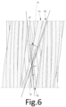
- the contact angle between the outer wires of the inner strand and the outer wires of the outer strands is the angle ⁇ f shown in the figure 6 .
- the axis AA' of the cable around which the inner layer of the cable and the outer layer of the cable are wound is shown.
- only one metal wire of the outer layer of the inner strand and one metal wire of the outer layer of the outer strand have been kept in order to better visualize the angle ⁇ f which is the contact angle between the outer metal wire of the inner strand and the metal wire external of the external strand. This is one of the relevant parameters for determining the embrittlement coefficient of the cable because the lower the contact angle, the less the embrittlement of the cable.
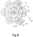
- the helix radius Re of the outer layer of the cable is the radius of the theoretical circle passing through the centers of the outer strands of the outer layer in a plane perpendicular to the axis of the cable.
- the inter-strand distance E of the outer layer of outer strands is defined, on a section of the cable perpendicular to the main axis of the cable, as the shortest distance which separates, on average, the circular envelopes in which two adjacent outer strands are inscribed.
- the inter-strand distance E is the distance between the 2 centers of 2 adjacent external strands, points A and B as shown in the figure 8 , minus the diameter of the outer strand.
- the wires of the same layer of a predetermined strand all have substantially the same diameter.
- the external strands all have substantially the same diameter.
- substantially the same diameter is meant that the wires or strands have the same diameter to within industrial tolerances.
- the inter-wire distance of a layer is defined, on a section of the cable perpendicular to the main axis of the cable, as the shortest distance which separates, on average, two adjacent wires of the layer.
- the sum SI3' is the sum of the inter-wire distances separating each pair of adjacent external wires of the external layer.
- the inter-wire distance I2' is the distance between 2 intermediate metal wire centers minus the wire diameter. The calculation is the same as previously described.
- the sum SI2' is the sum of the inter-wire distances separating each pair of adjacent intermediate wires of the outer layer.
- the strands do not undergo pre-forming.
- the cable is metallic.
- a metallic cable is meant a cable formed of wires consisting mainly (i.e. for more than 50% of these wires) or entirely (for 100% of the wires) of a metallic material.
- a metallic material is preferably implemented with a steel material, more preferably in pearlitic (or ferrito-pearlitic) carbon steel hereinafter referred to as "carbon steel”, or in stainless steel (by definition, steel comprising at least 11% chromium and at least 50% iron). But it is of course possible to use other steels or other alloys.
- its carbon content (% by weight of steel) is preferably between 0.4% and 1.2%, in particular between 0.5% and 1.1%; these contents represent a good compromise between the mechanical properties required for the tire and the feasibility of the wires.
- the metal or steel used may itself be coated with a metal layer improving, for example, the implementation properties of the metal cable and/or its constituent elements, or the usage properties of the cable and/or tire themselves, such as adhesion properties, corrosion resistance or even resistance to aging.
- the steel used is covered with a layer of brass (Zn-Cu alloy) or zinc.
- the external strands are wound in a helix around the internal strand at a pitch ranging from 30 mm to 100 mm and preferably ranging from 50 mm to 90 mm.
- the invention also relates to a cable as described above extracted from a polymer matrix.
- the polymer matrix is an elastomeric matrix.
- the polymeric matrix preferably elastomeric, is based on a polymeric composition, preferably elastomeric.
- polymer matrix is meant a matrix comprising at least one polymer.
- the polymer matrix is thus based on a polymer composition.
- elastomeric matrix a matrix comprising at least one elastomer.
- the preferred elastomeric matrix is thus based on an elastomeric composition.
- the composition comprises the mixture and/or the in situ reaction product of the different constituents used, some of these constituents being able to react and/or being intended to react with each other, at least partially, during the different phases of manufacture of the composition; the composition thus being able to be in a totally or partially crosslinked state or in a non-crosslinked state.
- polymeric composition that the composition comprises at least one polymer.
- a polymer may be a thermoplastic, for example a polyester or a polyamide, a thermosetting polymer, an elastomer, for example natural rubber, a thermoplastic elastomer or a mixture of these polymers.
- elastomeric composition it is meant that the composition comprises at least one elastomer and at least one other component.
- the composition comprising at least one elastomer and at least one other component comprises an elastomer, a crosslinking system and a filler.
- a ply in a tire is formed from the previously described cord embedded in the elastomeric composition.
- compositions that can be used for these plies are conventional compositions for calendering reinforcing wire elements and comprise a diene elastomer, for example natural rubber, a reinforcing filler, for example carbon black and/or silica, a crosslinking system, for example a vulcanization system, preferably comprising sulfur, stearic acid and zinc oxide, and optionally a vulcanization accelerator and/or retarder and/or various additives.
- a metal coating for example a layer of brass.
- the values of the characteristics described in the present application for the extracted cable are measured on or determined from cables extracted from a polymer matrix, in particular an elastomeric matrix, for example from a tire.
- a polymer matrix in particular an elastomeric matrix
- the strip of material is removed radially outside the cable to be extracted so as to see the cable to be extracted radially flush with the polymer matrix. This removal can be done by peeling using pliers and knives or by planing.
- the end of the cable to be extracted is released using a knife.
- the cable is pulled so as to extract it from the matrix by applying a relatively small angle so as not to plasticize the cable to be extracted.
- the extracted cables are then carefully cleaned, for example using a knife, so as to detach the remains of polymer matrix locally attached to the cable and taking care not to damage the surface of the metal wires.
- SL is greater than 25,000 MPa.mm because we are looking for a rather large footprint by maximizing the metal mass.
- Ec ⁇ 0.47 and preferably Ec ⁇ 0.48 are advantageousously, Ec ⁇ 0.47 and preferably Ec ⁇ 0.48.
- Ec ⁇ 0.65 and preferably Ec ⁇ 0.55 are advantageousously, compared to each other.
- ⁇ f is greater than or equal to 0° and preferably greater than or equal to 3°.
- ⁇ f is less than or equal to 25° and preferably less than or equal to 20°.
- ⁇ t is greater than or equal to 0° and preferably greater than or equal to 3°.
- ⁇ t is less than or equal to 20°, preferably less than or equal to 15° and more preferably less than or equal to 10°.
- angles ⁇ f and ⁇ t are expressed in radians, i.e. the value in degrees multiplied by ⁇ and divided by 180°.
- each metal wire of the cable comprises a steel core having a composition conforming to standard NF EN 10020 of September 2000 and a carbon content C ⁇ 0.80%.
- each metal wire of the cable comprises a steel core having a composition in accordance with standard NF EN 10020 of September 2000 and a carbon content C > 0.80%, preferably C ⁇ 0.82%.
- steel compositions include non-alloy steels (points 3.2.1 and 4.1 of standard NF EN 10020 of September 2000), stainless steels (points 3.2.2 and 4.2 of standard NF EN 10020 of September 2000) and other alloy steels (points 3.2.3 and 4.3 of standard NF EN 10020 of September 2000).
- a relatively high carbon content makes it possible to achieve the mechanical strength of the metal wires of the cables according to the invention.
- each metal wire of the cable comprises a steel core having a composition in accordance with standard NF EN 10020 of September 2000 and a carbon content C ⁇ 1.20% and preferably C ⁇ 1.10%.
- the use of too high a carbon content is of a relatively expensive part and on the other hand leads to a reduction in the fatigue-corrosion endurance of the metal wires.
- d1, d1', d2, d2', d3, d3' range, independently of each other, from 0.12 mm to 0.38 mm and preferably from 0.15 mm to 0.35 mm.
- the cable is such that each outer layer of the outer strand is wound in a winding direction opposite to the winding direction of the cable and the outer layer of the inner strand is wound in the same winding direction as the winding direction of the cable.
- the winding direction of each outer wire of the outer strand in a winding direction opposite to the winding direction of each outer wire of the inner strand makes it possible to form less punctate and relatively more extensive contact zones promoting the efficiency coefficient.
- the cable is such that each outer layer of each outer strand and the outer layer of the inner strand are wound in the same winding direction as the winding direction of the cable.
- a more punctate and less linear contact zone is formed, which is less conducive to the efficiency coefficient but allows easier industrial implementation because all the layers are wound in the same direction and the cable is assembled in the same direction.
- each inner and intermediate layer of each outer strand is wound in the winding direction opposite to the winding direction of the cable, and the inner and intermediate layers of the inner strand are wound in the winding direction of the cable.
- each inner and intermediate layer of each outer strand and the inner and intermediate layers of the inner strand are wound according to the winding direction of the cable.
- the cable penetrability coefficient Cp is greater than or equal to 0.60 and preferably greater than or equal to 0.70. Indeed, there is sufficient space between the wires or strands to allow the passage of a polymeric composition, preferably elastomeric.
- the outer layer of the cable is desaturated.
- a desaturated layer is such that there is sufficient space between the threads to allow the passage of a polymeric, preferably elastomeric, composition.
- a desaturated layer means that the threads do not touch each other and that there is sufficient space between two adjacent threads to allow the passage of a polymeric, preferably elastomeric, composition.
- a saturated layer is such that there is not sufficient space between the threads of the layer to allow the passage of a polymeric, preferably elastomeric, composition, for example because the threads of the layer touch each other two by two.
- a desaturated cable layer is such that the inter-strand distance of the outer strands is greater than or equal to 30 ⁇ m.
- the inter-strand distance of the outer layer of outer strands is defined, on a section of the cable perpendicular to the main axis of the cable, as the shortest distance that separates, on average, the circular envelopes in which two adjacent outer strands are inscribed.
- the outer layer of the inner strand is desaturated.
- the inter-wire distance of the outer layer of the inner strand is greater than or equal to 10 ⁇ m.
- the inter-wire distance of the outer layer of the inner strand is greater than or equal to 15 ⁇ m.
- the inter-wire distance of the outer layer of the inner strand is less than or equal to 100 ⁇ m.
- the sum SI2 of the inter-wire distances I2 of the intermediate layer of the internal strand is greater than the diameter d2 of the intermediate wires of the intermediate layer.
- the sum SI3 of the inter-wire distances I3 of the outer layer of the inner strand is greater than the diameter d3 of the outer wires of the outer layer.
- each strand is of the type not gummed in situ.
- not gummed in situ it is meant that before assembling the strands together, each strand is made up of wires from the different layers and is free of polymeric composition, in particular elastomeric composition.
- each outer strand is desaturated.
- the inter-wire distance of the outer layer of each outer strand is greater than or equal to 10 ⁇ m.
- the inter-wire distance of the outer layer of each outer strand is greater than or equal to 15 ⁇ m.
- the inter-wire distance of the outer layer of each outer strand is less than or equal to 100 ⁇ m.
- the sum SI2' of the inter-wire distances I2' of the intermediate layer of each external strand is greater than the diameter d2' of the intermediate wires of the intermediate layer.
- the sum SI3' of the inter-wire distances I3' of the outer layer of each outer strand is greater than or equal to the diameter d3' of the outer wires of the outer layer.
- the outer layer of the inner strand is wrapped around the intermediate layer of the inner strand in contact with the intermediate layer of the inner strand and the intermediate layer of the inner strand is wrapped around the inner layer of the inner strand in contact with the inner layer of the inner strand.
- the outer layer of the outer strand is wrapped around the intermediate layer of the outer strand in contact with the intermediate layer of the outer strand and the intermediate layer of the outer strand is wrapped around the inner layer of the outer strand in contact with the inner layer of the outer strand.
- L 6, 7 or 8
- the most severe transverse forces are the transverse forces exerted by the outer strands on the inner strand.
- each internal wire of the internal strand has a diameter d1 equal to the diameter d2 of each intermediate wire of the internal strand and equal to the diameter d3 of each external wire of the internal strand.
- the same wire diameter is preferably used on the internal, intermediate and external layers of the internal strand, which limits the number of different wires to be managed during the manufacture of the cable.
- each intermediate wire of the outer strand has a diameter d2' equal to the diameter d3' of each outer wire of the outer strand.
- the same wire diameter is preferably used on the intermediate and outer layers of the outer strand, which limits the number of different wires to be managed during the manufacture of the cable.
- Another object of the invention is a reinforced product comprising a polymer matrix and at least one cable as defined above.
- the reinforced product comprises one or more cables according to the invention embedded in the polymer matrix, and in the case of several cables, the cables are arranged side by side in a main direction.
- Another object of the invention is a tire comprising at least one cable as defined above.
- the tire comprises a carcass reinforcement anchored in two beads and surmounted radially by a crown reinforcement itself surmounted by a tread, the carcass reinforcement comprising at least one cable as defined above.
- the cable is particularly intended for industrial vehicles selected from heavy vehicles such as "Heavy goods vehicles” - i.e., metro, bus, road transport vehicles (trucks, tractors, trailers), off-road vehicles -, agricultural or civil engineering vehicles, other transport or handling vehicles.
- heavy vehicles such as "Heavy goods vehicles” - i.e., metro, bus, road transport vehicles (trucks, tractors, trailers), off-road vehicles -, agricultural or civil engineering vehicles, other transport or handling vehicles.
- the tire is for civil engineering type vehicles.
- the tire has a dimension in which the diameter, in inches, of the seat of the rim on which the tire is intended to be mounted is greater than or equal to 25 inches, preferably 39 to 63 inches.
- the invention also relates to a rubber article comprising an assembly according to the invention, or an impregnated assembly according to the invention.
- rubber article is meant any type of rubber article such as a ball, a non-pneumatic object such as a non-pneumatic tire, a conveyor belt or a caterpillar.
- the “median circumferential plane” M of the tire is the plane which is normal to the axis of rotation of the tire and which is located equidistant from the annular reinforcement structures of each bead.
- the 10 tire is for heavy vehicles of the civil engineering type, for example of the “dumper” type.
- the 10 tire has a dimension of type 53/80 R 63.
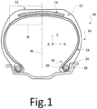
- the tire 10 comprises a crown 12 reinforced by a crown reinforcement 14, two sidewalls 16 and two beads 18, each of these beads 18 being reinforced with an annular structure, here a bead wire 20.
- the crown reinforcement 14 is radially surmounted by a tread 22 and joined to the beads 18 by the sidewalls 16.
- a carcass reinforcement 24 is anchored in the two beads 18, and is here wound around the two bead wires. 20 and comprises a turn-up 26 arranged towards the outside of the tire 20 which is here shown mounted on a rim 28.
- the carcass reinforcement 24 is radially surmounted by the crown reinforcement 14.
- the carcass reinforcement 24 comprises at least one carcass ply 30 reinforced by radial carcass cables 50 according to the invention (not shown).
- the carcass cables 50 are arranged substantially parallel to each other and extend from one bead 18 to the other so as to form an angle of between 80° and 90° with the median circumferential plane M (plane perpendicular to the axis of rotation of the tire which is located midway between the two beads 18 and passes through the middle of the crown reinforcement 14).
- the tire 10 also includes a sealing ply 32 made of an elastomer (commonly called inner rubber) which defines the radially inner face 34 of the tire 10 and which is intended to protect the carcass ply 30 from the diffusion of air coming from the space inside the tire 10.
- a sealing ply 32 made of an elastomer (commonly called inner rubber) which defines the radially inner face 34 of the tire 10 and which is intended to protect the carcass ply 30 from the diffusion of air coming from the space inside the tire 10.
- the crown reinforcement 14 comprises, radially from the outside to the inside of the tire 10, a protective reinforcement 36 arranged radially inside the tread 22, a working reinforcement 38 arranged radially inside the protective reinforcement 36 and an additional reinforcement 40 arranged radially inside the working reinforcement 38.
- the protective reinforcement 36 is thus radially intercalated between the tread 22 and the working reinforcement 38.
- the working reinforcement 38 is radially intercalated between the protective reinforcement 36 and the additional reinforcement 40.
- the protective frame 36 comprises first and second protective plies 42, 44 comprising protective metal cables, the first ply 42 being arranged radially inside the second ply 44.
- the protective metal cables make an angle at least equal to 10°, preferably ranging from 10° to 35° and preferentially from 15° to 30° with the circumferential direction Z of the tire.
- the working frame 38 comprises first and second working plies 46, 48, the first ply 46 being arranged radially inside the second ply 48.
- the additional frame 40 also called a limiter block, the function of which is to partially absorb the mechanical stresses of inflation, comprises, for example and in a manner known per se, additional metal reinforcement elements, for example as described in FR 2 419 181 Or FR 2 419 182 making an angle at most equal to 10°, preferably ranging from 5° to 10° with the circumferential direction Z of the tire 10.
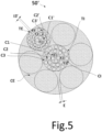
- the reinforced product 100 comprises at least one cable 50, in this case several cables 50, embedded in the polymer matrix 102.
- the polymer matrix 102 and the cables 50 are shown in a X, Y, Z coordinate system in which the Y direction is the radial direction and the X and Z directions are the axial and circumferential directions.
- the reinforced product 100 comprises several cables 50 arranged side by side along the main direction X and extending parallel to each other within the reinforced product 100 and collectively embedded in the polymer matrix 102.
- the polymer matrix 102 is an elastomeric matrix based on an elastomeric composition.
- the 50 and 50' cables have the same geometric structure.
- the 50' cable is obtained after extraction of the 10 tire.
- the 50 cable and the 50' extracted cable are metallic and of the multi-strand type with two cylindrical layers.
- the layers of strands constituting the 50 or 50' cable are two in number, no more, no less.
- the outer layer CE consists of L>1 outer strands TE wound around the inner layer CI of the cable.
- the penetrability coefficient of cables 50 and 50' is equal to 0.98 which is greater than or equal to 0.60 and preferably greater than or equal to 0.70.
- the outer layer of cables 50 and 50' is desaturated.
- the inter-strand distance E of the outer strands is strictly greater than 20 ⁇ m.
- E 80 ⁇ m.
- ⁇ f is greater than or equal to 0° and preferably greater than or equal to 3° and less than or equal to 25° and preferably greater than or equal to 20°.
- ⁇ f 6.6°.
- ⁇ t is greater than or equal to 0° and preferably greater than or equal to 3° and less than or equal to 20°, preferably less than or equal to 15° and more preferably less than or equal to 10°.
- ⁇ t 8.1°.
- the outer layer C3 of each inner strand TI is desaturated.
- the inter-wire distance of the outer layer of the inner strand is greater than or equal to 30 ⁇ m, and here equal to 46 ⁇ m.
- the sum SI3 of the inter-wire distances I3 of the outer layer C3 is greater than the diameter d3 of the outer wires F3 of the outer layer C3.
- d1 d2 and d3 range, independently of each other, from 0.12 to 0.38 mm and preferably from 0.15 to 0.35 mm.
- the outer layer C3' of each outer strand TE is desaturated. Being desaturated, the inter-wire distance I3' of the outer layer C3' separating on average the N' outer wires is greater than or equal to 10 ⁇ m.
- the inter-wire distance I3' of the outer layer of each outer strand is greater than or equal to 30 ⁇ m, and here equal to 43 ⁇ m.
- the sum SI3' of the inter-wire distances I3' of the outer layer C3' is greater than the diameter d3' of the outer wires F3' of the outer layer C3'.
- Each outer layer C3' of the outer strand TE is wound in a winding direction opposite to the winding direction of the rope, and the outer layer C3 of the inner strand TI is wound in the same winding direction as the winding direction of the rope.
- each inner layer C1' and intermediate layer C2' of each outer strand TE is wound in the winding direction opposite to the winding direction of the rope, and the inner layer C1 and intermediate layer C2 of the inner strand TI are wound in the winding direction of the rope.
- the winding direction of layers C1, C2, C3 and the rope is Z
- that of layers C1', C2' and C3' is S.
- torque balancing is meant here, in a manner well known to those skilled in the art, the cancellation of residual torsional torques (or of the elastic return of torsion) exerted on each wire of the strand, in the intermediate layer as in the external layer.
- each strand is wound onto one or more receiving reels for storage, before the subsequent assembly operation by cabling the elementary strands to obtain the multi-strand cable.
- the procedure is well known to those skilled in the art, by cabling or twisting the strands previously obtained, using cabling or twisting machines sized to assemble strands.
- the hoop F is wound at pitch pf in direction S around the assembly previously obtained.
- the cable 50 is then incorporated by calendering into composite fabrics formed from a known composition based on natural rubber and carbon black as a reinforcing filler, conventionally used for the manufacture of crown reinforcements of radial tires.
- This composition essentially comprises, in addition to the elastomer and the reinforcing filler (carbon black), an antioxidant, stearic acid, an extender oil, cobalt naphthenate as an adhesion promoter, and finally a vulcanization system (sulfur, accelerator, ZnO).
- the composite fabrics reinforced by these cables comprise an elastomeric composition matrix formed by two thin layers of elastomeric composition which are superimposed on either side of the cables and which have a thickness ranging from 1 and 4 mm respectively.
- the calendering pitch (cable laying pitch in the elastomeric composition fabric) ranges from 4 mm to 8 mm.
- Table 3 summarizes the characteristics of the C1 control cable and the EDT state-of-the-art cable (cable 189.23).
- Tables 2 and 3 show that the 50, 50' and 60 cables have a relatively low bending endurance criterion compared to the state-of-the-art cable EDT and the control cable C1 while having a sufficient bulk criterion.
- the EDT and C1 cables have a relatively high bending endurance criterion which does not make it possible to effectively reduce the stresses in the cable during bending stress.
- the cables according to the invention have a bending endurance criterion SL ⁇ 40,000 MPa.mm sufficiently low to overcome these drawbacks while maintaining a satisfactory bulk.
Landscapes
- Engineering & Computer Science (AREA)
- Mechanical Engineering (AREA)
- Ropes Or Cables (AREA)
- Chemical & Material Sciences (AREA)
- Materials Engineering (AREA)
- Tires In General (AREA)
- Inorganic Chemistry (AREA)
- Manufacturing & Machinery (AREA)
- Health & Medical Sciences (AREA)
- Chemical Kinetics & Catalysis (AREA)
- Medicinal Chemistry (AREA)
- Polymers & Plastics (AREA)
- Organic Chemistry (AREA)
Claims (13)
- Mehrlitziges Seil (50) mit zwei Lagen, umfassend:- eine innere Lage (CI) des Seils, die aus K = 1 inneren Litze (TI) mit drei Lagen (C1, C2, C3) besteht, umfassend:dadurch gekennzeichnet, dass- eine innere Lage (C1), die aus Q = 1, 2, 3 oder 4 inneren Metalldrähten (F1) mit einem Durchmesser d1 besteht,- eine mittlere Lage (C2), die aus M mittleren Metalldrähten (F2) mit einem Durchmesser d2 besteht, die um die innere Lage (C1) gewickelt sind, und- eine äußere Lage (C3), die aus N äußeren Metalldrähten (F3) mit einem Durchmesser d3 besteht, die um die mittlere Lage (C2) gewickelt sind,- eine äußere Lage (CE) des Seils, die aus L > 1 äußeren Litzen (TE) mit drei Lagen (C1', C2', C3') besteht, die um die innere Lage (CI) des Seils gewickelt sind, umfassend:- eine innere Lage (C1'), die aus Q' = 1, 2, 3 oder 4 inneren Metalldrähten (F1') mit einem Durchmesser d1' besteht,- eine mittlere Lage (C2'), die aus M' mittleren Metalldrähten (F2') mit einem Durchmesser d2' besteht, die um die innere Lage (C1') gewickelt sind, und- eine äußere Lage (C3'), die aus N' äußeren Metalldrähten (F3') mit einem Durchmesser d3' besteht, die um die mittlere Lage (C2') gewickelt sind,das Seil (50) aufweist:- ein Biegefestigkeitskriterium SL ≤ 40000 MPa.mm mit
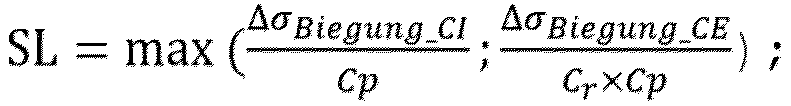 - ein Abmessungskriterium Ec ≥ 0,46 mit Ec = Sc/Se,worin:- ΔσBiegung_CI = MStahl × Max(d1; d1'; d2; d2')/2 in MPa.mm die maximale Biegebeanspruchung pro Krümmungseinheit der inneren Drähte (F1; F1') der inneren und äußeren Litzen oder der mittleren Drähte (F2; F2') der inneren und äußeren Litzen ist;- ΔσBiegung_CE = MStahl × Max(d3; d3')/2 in MPa.mm die maximale Biegebeanspruchung je Krümmungseinheit der äußeren Metalldrähte (F3; F3') der inneren und äußeren Litzen ist;- MStahl = 210.000 MPa der Modul des Stahls ist;- d1, d1', d2, d2', d3 und d3' in mm ausgedrückt sind,
 - CP der Durchdringbarkeitskoeffizient des Seils ist, wobei Cp IT der Durchdringbarkeitskoeffizient zwischen Litzen ist und Cp TE der Durchdringbarkeitskoeffizient der äußeren Litzen ist, mit:- einem Zwischenlitzenabstand E der äußeren Litzen (TE) der äußeren Lage (CE) des Seils, und- Cp IT = 1,0, wenn E > 70 µm; oder- Cp IT = 0,015 × E - 0,05, wenn 30 um ≤ E ≤ 70 um; und
 wobei CpC2' der Durchdringbarkeitskoeffizient der mittleren Lage (C2') der äußeren Litze (TE) ist und CpC3' der Durchdringbarkeitskoeffizient der äußeren Lage (C3') der äußeren Litze (TE) ist, wobei:Cp C2' = 0,4, wenn der Zwischendrahtabstand 12' der mittleren Metalldrähte (F2') der mittleren Lage (C2') 12' < 10 µm; oder- Cp C2' = 1,0, wenn I2' > 40 µm; oder- Cp C2' = 0,02 × I2' + 0,2, wenn 10 um ≤ 12' ≤ 40 µm, undCp C3' = 0,4, wenn der Zwischendrahtabstand 13' der äußeren Metalldrähte (F3') der äußeren Lage (C3') 13' < 10 µm; oder- Cp C3' - 1,0, wenn 13' > 40 µm; oder- Cp C3' - 0,02 × I3' + 0,2, wenn 10 um ≤ 13' ≤ 40 µm,- Cr der Wirkungsgrad des Seils (50) ohne Einheit ist mit
 d3 und d3' in mm ausgedrückt sind,αf der Kontaktwinkel zwischen den äußeren Metalldrähten (F3) der inneren Litze (TI) und den äußeren Metalldrähten (F3') der äußeren Litzen (TE) ist, ausgedrückt in Radiant,αt der Steigungswinkel jeder äußeren Litze (TE) ist, ausgedrückt in Radiant;
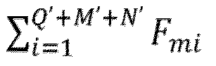 Cste = 1500 N.mm-2;D der Durchmesser des Seils in mm ist;Sc die verdichtete Fläche in mm2 ist mit Sc=[Q × (d1/2)2+M × (d2/2)2 + N × (d3/2)2 + L × (Q' ×(d1' /2)2+ M' × (d2'/2)2 + N' × (d3'/2)2)] × π und Se die Abmessungsfläche des Seils (50) in mm2 Se = π × (D/2)2 ist;wobei die äußere Lage (CE) des Seils so entsättigt ist, dass der Zwischenlitzenabstand E der äußeren Litzen (TE), der, über einen zur Hauptachse des Seils (50) senkrechten Abschnitt des Seils, als der kürzeste Abstand definiert ist, der im Durchschnitt die kreisförmigen Hüllen trennt, in die zwei benachbarte äußere Litzen (TE) einbeschrieben sind, größer als oder gleich 30 µm ist; undwobei die äußere Lage (C3') jeder äußeren Litze (TE) entsättigt ist.
 - Seil (50) nach dem vorangehenden Anspruch, wobei SL ≤ 37.500 MPa.mm und vorzugsweise SL ≤ 35.000 MPa.mm.
- Seil (50) nach einem der vorhergehenden Ansprüche, wobei SL ≥ 25.000 MPa.mm und vorzugsweise SL ≥ 27.500 MPa.mm.
- Seil (50) nach einem der vorangehenden Ansprüche, wobei Ec ≥ 0,47 und vorzugsweise Ec ≥ 0,48.
- Seil (5) nach einem der vorangehenden Ansprüche, wobei Ec ≤ 0,65 und vorzugsweise Ec ≤ 0,55.
- Seil (50) nach einem der vorhergehenden Ansprüche, wobei αf größer als oder gleich 0° und vorzugsweise größer als oder gleich 3° ist.
- Seil (50) nach einem der vorhergehenden Ansprüche, wobei αf kleiner als oder gleich 25° und vorzugsweise kleiner als oder gleich 20° ist.
- Seil (50) nach einem der vorhergehenden Ansprüche, wobei αt größer als oder gleich 0° und vorzugsweise größer als oder gleich 3° ist.
- Seil (50) nach einem der vorhergehenden Ansprüche, wobei αt kleiner als oder gleich 20°, vorzugsweise kleiner als oder gleich 15° und noch bevorzugter kleiner als oder gleich 10° ist.
- Seil (50) nach einem der vorhergehenden Ansprüche, wobei der Durchdringbarkeitskoeffizient des Seils Cp größer als oder gleich 0,60 und vorzugsweise größer als oder gleich 0,70 ist.
- Seil (50) nach einem der vorangehenden Ansprüche, das aus einer Polymermatrix mit einem der in der Beschreibung beschriebenen Extraktionsverfahren extrahiert wurde.
- Verstärktes Produkt (100), dadurch gekennzeichnet, dass es eine Polymermatrix (102) und mindestens ein Seil (50) nach einem der Ansprüche 1 bis 10 umfasst.
- Reifen (10), dadurch gekennzeichnet, dass er mindestens ein Seil (50) nach einem der Ansprüche 1 bis 10 oder ein verstärktes Produkt nach Anspruch 12 umfasst.
Applications Claiming Priority (2)
| Application Number | Priority Date | Filing Date | Title |
|---|---|---|---|
| FR2006604A FR3111923B1 (fr) | 2020-06-24 | 2020-06-24 | Câble multi-torons à deux couches à endurance sous flexion améliorée |
| PCT/FR2021/051104 WO2021260302A1 (fr) | 2020-06-24 | 2021-06-18 | Câble multi-torons à deux couches à endurance sous flexion améliorée |
Publications (2)
| Publication Number | Publication Date |
|---|---|
| EP4172406A1 EP4172406A1 (de) | 2023-05-03 |
| EP4172406B1 true EP4172406B1 (de) | 2024-10-02 |
Family
ID=72801622
Family Applications (1)
| Application Number | Title | Priority Date | Filing Date |
|---|---|---|---|
| EP21740134.8A Active EP4172406B1 (de) | 2020-06-24 | 2021-06-18 | Zweischichtiges mehradriges kabel mit verbesserter biegefestigkeit |
Country Status (7)
| Country | Link |
|---|---|
| US (1) | US12467199B2 (de) |
| EP (1) | EP4172406B1 (de) |
| JP (1) | JP7710473B2 (de) |
| KR (1) | KR20230027218A (de) |
| CN (1) | CN115997056B (de) |
| FR (1) | FR3111923B1 (de) |
| WO (1) | WO2021260302A1 (de) |
Families Citing this family (4)
| Publication number | Priority date | Publication date | Assignee | Title |
|---|---|---|---|---|
| FR3103500A1 (fr) * | 2019-11-22 | 2021-05-28 | Compagnie Generale Des Etablissements Michelin | Câble multi-torons à deux couches à énergie de rupture surfacique améliorée |
| FR3111921B1 (fr) | 2020-06-24 | 2022-06-17 | Michelin & Cie | Câble multi-torons à deux couches à endurance sous flexion améliorée |
| FR3122677B1 (fr) * | 2021-05-07 | 2024-07-12 | Michelin & Cie | Câble multi-torons à deux couches à énergie de rupture surfacique améliorée |
| CN115434172A (zh) * | 2022-08-26 | 2022-12-06 | 贵州钢绳股份有限公司 | 6×k36ws-iwr(k)结构压实股钢丝绳生产工艺 |
Family Cites Families (33)
| Publication number | Priority date | Publication date | Assignee | Title |
|---|---|---|---|---|
| DE2755667A1 (de) | 1977-12-14 | 1979-06-21 | Continental Gummi Werke Ag | Stahlseil als festigkeitstraeger in gummiartikeln, insbesondere in luftreifen |
| FR2419182A1 (fr) | 1978-03-10 | 1979-10-05 | Michelin & Cie | Pneumatique a carcasse radiale, notamment pour engins de genie civil |
| FR2419181A1 (fr) | 1978-03-10 | 1979-10-05 | Michelin & Cie | Perfectionnements aux pneumatiques a carcasse radiale |
| CA2109904C (en) * | 1992-12-18 | 2004-09-14 | Pol Bruyneel | Multi-strand steel cord |
| JPH10131066A (ja) | 1996-10-29 | 1998-05-19 | Bridgestone Corp | ゴム物品補強用スチールコードおよび空気入りラジアルタイヤ |
| JP2001114143A (ja) | 1999-10-18 | 2001-04-24 | Bridgestone Corp | 弾性クローラ |
| US6863103B1 (en) * | 1999-11-11 | 2005-03-08 | Bridgestone Corporation | Steel cord for the reinforcement of a rubber article and tire |
| JP5188123B2 (ja) | 2007-08-29 | 2013-04-24 | 株式会社ブリヂストン | ゴムクローラ用スチールコード |
| FR2947574B1 (fr) * | 2009-07-03 | 2012-11-09 | Michelin Soc Tech | Cable multitorons dont les torons elementaires sont des cables a deux couches gommes in situ. |
| EP2504485B1 (de) * | 2009-11-27 | 2014-07-30 | NV Bekaert SA | Offenes mehrstrangiges kabel |
| FR2953450B1 (fr) * | 2009-12-04 | 2011-11-18 | Michelin Soc Tech | Pneumatique comportant des cables d'armature de carcasse presentant des permeabilites differentes |
| FR2969037B1 (fr) * | 2010-12-21 | 2014-08-29 | Michelin Soc Tech | Pneumatique dont l'armature de carcasse est renforcee par une couche d'elements de renforcement dans la zone du bourrelet |
| FR2990963B1 (fr) * | 2012-05-25 | 2014-12-05 | Michelin & Cie | Cable metallique multi-torons a deux couches. |
| FR2996230B1 (fr) | 2012-09-28 | 2014-10-31 | Michelin & Cie | Cable gomme in situ comprenant une composition comprenant un polysulfure organique. |
| FR3014914B1 (fr) * | 2013-12-16 | 2016-12-09 | Michelin & Cie | Cable metallique multi-torons a deux couches |
| FR3014913B1 (fr) * | 2013-12-16 | 2016-12-09 | Michelin & Cie | Cable metallique multi-torons a deux couches |
| US10906353B2 (en) | 2014-07-28 | 2021-02-02 | Bridgestone Corporation | Steel cord for reinforcing rubber article |
| US20210188006A1 (en) | 2016-04-15 | 2021-06-24 | Bridgestone Corporation | Construction vehicle tire and steel cord |
| FR3060617A1 (fr) * | 2016-12-20 | 2018-06-22 | Compagnie Generale Des Etablissements Michelin | Cable multi-torons a deux couches a penetrabilite amelioree |
| FR3060616A1 (fr) * | 2016-12-20 | 2018-06-22 | Compagnie Generale Des Etablissements Michelin | Cable multi-torons a deux couches a penetrabilite amelioree |
| WO2018198776A1 (ja) | 2017-04-28 | 2018-11-01 | 株式会社ブリヂストン | ゴム物品補強用スチールコード、その製造方法及びタイヤ |
| JP6936059B2 (ja) * | 2017-06-30 | 2021-09-15 | 株式会社ブリヂストン | ゴム物品補強用スチールコード |
| CN110799700A (zh) | 2017-06-30 | 2020-02-14 | 株式会社普利司通 | 橡胶物品增强用钢丝帘线和其制造方法 |
| US11401656B2 (en) | 2017-12-19 | 2022-08-02 | Compagnie Generale Des Etablissments Michelin | Two-layer multi-strand cords having very low, low and medium moduli |
| WO2019122724A1 (fr) | 2017-12-19 | 2019-06-27 | Compagnie Generale Des Etablissements Michelin | Câbles multi-torons à deux couches à très bas, bas et moyen modules |
| US11319666B2 (en) | 2017-12-19 | 2022-05-03 | Compagnie Generale Des Etablissements Michelin | Two-layer multi-strand cords having very low, low and medium moduli |
| JP7330190B2 (ja) | 2017-12-19 | 2023-08-21 | コンパニー ゼネラール デ エタブリッスマン ミシュラン | 超低、低、及び中程度の弾性率を有する2層マルチストランドコード |
| JP7330191B2 (ja) | 2017-12-19 | 2023-08-21 | コンパニー ゼネラール デ エタブリッスマン ミシュラン | 超低、低、及び中程度の弾性率を有する2層マルチストランドコード |
| AU2019291195B2 (en) * | 2018-06-20 | 2025-05-22 | Compagnie Generale Des Etablissements Michelin | Double-layer multi-strand cord with improved penetrability |
| EP3810846B1 (de) * | 2018-06-20 | 2024-05-22 | Compagnie Generale Des Etablissements Michelin | Doppellagiges mehrfachstrangseil mit verbesserter durchlässigkeit |
| JP7454499B2 (ja) | 2018-09-11 | 2024-03-22 | 株式会社ブリヂストン | ゴム物品補強用スチールコード |
| JP7278744B2 (ja) | 2018-10-30 | 2023-05-22 | 株式会社ブリヂストン | エラストマー補強用コード |
| FR3103500A1 (fr) | 2019-11-22 | 2021-05-28 | Compagnie Generale Des Etablissements Michelin | Câble multi-torons à deux couches à énergie de rupture surfacique améliorée |
-
2020
- 2020-06-24 FR FR2006604A patent/FR3111923B1/fr active Active
-
2021
- 2021-06-18 EP EP21740134.8A patent/EP4172406B1/de active Active
- 2021-06-18 WO PCT/FR2021/051104 patent/WO2021260302A1/fr not_active Ceased
- 2021-06-18 KR KR1020237002160A patent/KR20230027218A/ko active Pending
- 2021-06-18 JP JP2022580148A patent/JP7710473B2/ja active Active
- 2021-06-18 US US18/012,327 patent/US12467199B2/en active Active
- 2021-06-18 CN CN202180044609.7A patent/CN115997056B/zh active Active
Also Published As
| Publication number | Publication date |
|---|---|
| WO2021260302A1 (fr) | 2021-12-30 |
| JP7710473B2 (ja) | 2025-07-18 |
| US20230250580A1 (en) | 2023-08-10 |
| EP4172406A1 (de) | 2023-05-03 |
| FR3111923B1 (fr) | 2022-06-17 |
| KR20230027218A (ko) | 2023-02-27 |
| FR3111923A1 (fr) | 2021-12-31 |
| JP2023533212A (ja) | 2023-08-02 |
| CN115997056B (zh) | 2024-09-13 |
| CN115997056A (zh) | 2023-04-21 |
| US12467199B2 (en) | 2025-11-11 |
Similar Documents
| Publication | Publication Date | Title |
|---|---|---|
| EP4172406B1 (de) | Zweischichtiges mehradriges kabel mit verbesserter biegefestigkeit | |
| EP4061996B1 (de) | Zweischichtiges mehradriges kabel mit einer verbesserten oberflächenenergie bis zum bruch | |
| EP4172408B1 (de) | Zweischichtiges mehradriges kabel mit verbesserter biegefestigkeit | |
| EP4172405B1 (de) | Zweischichtiges mehradriges kabel mit verbesserter biegefestigkeit | |
| EP4172407B1 (de) | Zweischichtiges mehradriges kabel mit verbesserter biegefestigkeit | |
| EP4058628B1 (de) | Zweischichtiges mehradriges kabel, das eine ummantelte innenschicht und verbesserte leistung aufweist | |
| FR3130858A1 (fr) | Câble multi-torons à deux couches à endurance sous flexion améliorée | |
| FR3122674A1 (fr) | Câble multi-torons à deux couches à énergie de rupture surfacique améliorée | |
| WO2025008148A1 (fr) | Câble multi-torons à deux couches de multi-torons | |
| FR3122678A1 (fr) | Câble multi-torons à deux couches à énergie de rupture surfacique améliorée | |
| EP4334524A1 (de) | Zweischichtiges mehradriges kabel mit verbesserter oberflächenbruchenergie | |
| FR3122673A1 (fr) | Câble multi-torons à deux couches à énergie de rupture surfacique améliorée | |
| FR3122675A1 (fr) | Câble multi-torons à deux couches à énergie de rupture surfacique améliorée | |
| EP4334523A1 (de) | Zweischichtiges mehradriges kabel mit verbesserter bruchflächenenergie | |
| EP4334141A1 (de) | Zweischichtiges mehradriges kabel mit verbesserter oberflächenbruchenergie | |
| WO2025008147A1 (fr) | Câble multi-torons à deux couches de multi-torons | |
| FR3136788A1 (fr) | Câble multi-torons à deux couches de multi-torons | |
| FR3136790A1 (fr) | Câble multi-torons à deux couches de multi-torons |
Legal Events
| Date | Code | Title | Description |
|---|---|---|---|
| STAA | Information on the status of an ep patent application or granted ep patent |
Free format text: STATUS: UNKNOWN |
|
| STAA | Information on the status of an ep patent application or granted ep patent |
Free format text: STATUS: THE INTERNATIONAL PUBLICATION HAS BEEN MADE |
|
| PUAI | Public reference made under article 153(3) epc to a published international application that has entered the european phase |
Free format text: ORIGINAL CODE: 0009012 |
|
| STAA | Information on the status of an ep patent application or granted ep patent |
Free format text: STATUS: REQUEST FOR EXAMINATION WAS MADE |
|
| 17P | Request for examination filed |
Effective date: 20230124 |
|
| AK | Designated contracting states |
Kind code of ref document: A1 Designated state(s): AL AT BE BG CH CY CZ DE DK EE ES FI FR GB GR HR HU IE IS IT LI LT LU LV MC MK MT NL NO PL PT RO RS SE SI SK SM TR |
|
| DAV | Request for validation of the european patent (deleted) | ||
| DAX | Request for extension of the european patent (deleted) | ||
| GRAP | Despatch of communication of intention to grant a patent |
Free format text: ORIGINAL CODE: EPIDOSNIGR1 |
|
| STAA | Information on the status of an ep patent application or granted ep patent |
Free format text: STATUS: GRANT OF PATENT IS INTENDED |
|
| INTG | Intention to grant announced |
Effective date: 20240510 |
|
| GRAS | Grant fee paid |
Free format text: ORIGINAL CODE: EPIDOSNIGR3 |
|
| GRAA | (expected) grant |
Free format text: ORIGINAL CODE: 0009210 |
|
| STAA | Information on the status of an ep patent application or granted ep patent |
Free format text: STATUS: THE PATENT HAS BEEN GRANTED |
|
| AK | Designated contracting states |
Kind code of ref document: B1 Designated state(s): AL AT BE BG CH CY CZ DE DK EE ES FI FR GB GR HR HU IE IS IT LI LT LU LV MC MK MT NL NO PL PT RO RS SE SI SK SM TR |
|
| REG | Reference to a national code |
Ref country code: GB Ref legal event code: FG4D Free format text: NOT ENGLISH |
|
| REG | Reference to a national code |
Ref country code: CH Ref legal event code: EP |
|
| REG | Reference to a national code |
Ref country code: DE Ref legal event code: R096 Ref document number: 602021019612 Country of ref document: DE |
|
| REG | Reference to a national code |
Ref country code: IE Ref legal event code: FG4D Free format text: LANGUAGE OF EP DOCUMENT: FRENCH |
|
| REG | Reference to a national code |
Ref country code: LT Ref legal event code: MG9D |
|
| REG | Reference to a national code |
Ref country code: NL Ref legal event code: MP Effective date: 20241002 |
|
| REG | Reference to a national code |
Ref country code: AT Ref legal event code: MK05 Ref document number: 1728580 Country of ref document: AT Kind code of ref document: T Effective date: 20241002 |
|
| PG25 | Lapsed in a contracting state [announced via postgrant information from national office to epo] |
Ref country code: NL Free format text: LAPSE BECAUSE OF FAILURE TO SUBMIT A TRANSLATION OF THE DESCRIPTION OR TO PAY THE FEE WITHIN THE PRESCRIBED TIME-LIMIT Effective date: 20241002 |
|
| PG25 | Lapsed in a contracting state [announced via postgrant information from national office to epo] |
Ref country code: NL Free format text: LAPSE BECAUSE OF FAILURE TO SUBMIT A TRANSLATION OF THE DESCRIPTION OR TO PAY THE FEE WITHIN THE PRESCRIBED TIME-LIMIT Effective date: 20241002 |
|
| PG25 | Lapsed in a contracting state [announced via postgrant information from national office to epo] |
Ref country code: IS Free format text: LAPSE BECAUSE OF FAILURE TO SUBMIT A TRANSLATION OF THE DESCRIPTION OR TO PAY THE FEE WITHIN THE PRESCRIBED TIME-LIMIT Effective date: 20250202 Ref country code: PT Free format text: LAPSE BECAUSE OF FAILURE TO SUBMIT A TRANSLATION OF THE DESCRIPTION OR TO PAY THE FEE WITHIN THE PRESCRIBED TIME-LIMIT Effective date: 20250203 Ref country code: HR Free format text: LAPSE BECAUSE OF FAILURE TO SUBMIT A TRANSLATION OF THE DESCRIPTION OR TO PAY THE FEE WITHIN THE PRESCRIBED TIME-LIMIT Effective date: 20241002 |
|
| PG25 | Lapsed in a contracting state [announced via postgrant information from national office to epo] |
Ref country code: FI Free format text: LAPSE BECAUSE OF FAILURE TO SUBMIT A TRANSLATION OF THE DESCRIPTION OR TO PAY THE FEE WITHIN THE PRESCRIBED TIME-LIMIT Effective date: 20241002 |
|
| PG25 | Lapsed in a contracting state [announced via postgrant information from national office to epo] |
Ref country code: BG Free format text: LAPSE BECAUSE OF FAILURE TO SUBMIT A TRANSLATION OF THE DESCRIPTION OR TO PAY THE FEE WITHIN THE PRESCRIBED TIME-LIMIT Effective date: 20241002 |
|
| PG25 | Lapsed in a contracting state [announced via postgrant information from national office to epo] |
Ref country code: ES Free format text: LAPSE BECAUSE OF FAILURE TO SUBMIT A TRANSLATION OF THE DESCRIPTION OR TO PAY THE FEE WITHIN THE PRESCRIBED TIME-LIMIT Effective date: 20241002 |
|
| PG25 | Lapsed in a contracting state [announced via postgrant information from national office to epo] |
Ref country code: NO Free format text: LAPSE BECAUSE OF FAILURE TO SUBMIT A TRANSLATION OF THE DESCRIPTION OR TO PAY THE FEE WITHIN THE PRESCRIBED TIME-LIMIT Effective date: 20250102 |
|
| PG25 | Lapsed in a contracting state [announced via postgrant information from national office to epo] |
Ref country code: GR Free format text: LAPSE BECAUSE OF FAILURE TO SUBMIT A TRANSLATION OF THE DESCRIPTION OR TO PAY THE FEE WITHIN THE PRESCRIBED TIME-LIMIT Effective date: 20250103 Ref country code: LV Free format text: LAPSE BECAUSE OF FAILURE TO SUBMIT A TRANSLATION OF THE DESCRIPTION OR TO PAY THE FEE WITHIN THE PRESCRIBED TIME-LIMIT Effective date: 20241002 Ref country code: AT Free format text: LAPSE BECAUSE OF FAILURE TO SUBMIT A TRANSLATION OF THE DESCRIPTION OR TO PAY THE FEE WITHIN THE PRESCRIBED TIME-LIMIT Effective date: 20241002 |
|
| PG25 | Lapsed in a contracting state [announced via postgrant information from national office to epo] |
Ref country code: PL Free format text: LAPSE BECAUSE OF FAILURE TO SUBMIT A TRANSLATION OF THE DESCRIPTION OR TO PAY THE FEE WITHIN THE PRESCRIBED TIME-LIMIT Effective date: 20241002 Ref country code: CZ Free format text: LAPSE BECAUSE OF FAILURE TO SUBMIT A TRANSLATION OF THE DESCRIPTION OR TO PAY THE FEE WITHIN THE PRESCRIBED TIME-LIMIT Effective date: 20241002 |
|
| PG25 | Lapsed in a contracting state [announced via postgrant information from national office to epo] |
Ref country code: RS Free format text: LAPSE BECAUSE OF FAILURE TO SUBMIT A TRANSLATION OF THE DESCRIPTION OR TO PAY THE FEE WITHIN THE PRESCRIBED TIME-LIMIT Effective date: 20250102 |
|
| PG25 | Lapsed in a contracting state [announced via postgrant information from national office to epo] |
Ref country code: SM Free format text: LAPSE BECAUSE OF FAILURE TO SUBMIT A TRANSLATION OF THE DESCRIPTION OR TO PAY THE FEE WITHIN THE PRESCRIBED TIME-LIMIT Effective date: 20241002 |
|
| REG | Reference to a national code |
Ref country code: DE Ref legal event code: R097 Ref document number: 602021019612 Country of ref document: DE |
|
| PGFP | Annual fee paid to national office [announced via postgrant information from national office to epo] |
Ref country code: DE Payment date: 20250618 Year of fee payment: 5 |
|
| PG25 | Lapsed in a contracting state [announced via postgrant information from national office to epo] |
Ref country code: DK Free format text: LAPSE BECAUSE OF FAILURE TO SUBMIT A TRANSLATION OF THE DESCRIPTION OR TO PAY THE FEE WITHIN THE PRESCRIBED TIME-LIMIT Effective date: 20241002 |
|
| PG25 | Lapsed in a contracting state [announced via postgrant information from national office to epo] |
Ref country code: EE Free format text: LAPSE BECAUSE OF FAILURE TO SUBMIT A TRANSLATION OF THE DESCRIPTION OR TO PAY THE FEE WITHIN THE PRESCRIBED TIME-LIMIT Effective date: 20241002 |
|
| PGFP | Annual fee paid to national office [announced via postgrant information from national office to epo] |
Ref country code: FR Payment date: 20250627 Year of fee payment: 5 |
|
| PG25 | Lapsed in a contracting state [announced via postgrant information from national office to epo] |
Ref country code: RO Free format text: LAPSE BECAUSE OF FAILURE TO SUBMIT A TRANSLATION OF THE DESCRIPTION OR TO PAY THE FEE WITHIN THE PRESCRIBED TIME-LIMIT Effective date: 20241002 |
|
| PG25 | Lapsed in a contracting state [announced via postgrant information from national office to epo] |
Ref country code: SK Free format text: LAPSE BECAUSE OF FAILURE TO SUBMIT A TRANSLATION OF THE DESCRIPTION OR TO PAY THE FEE WITHIN THE PRESCRIBED TIME-LIMIT Effective date: 20241002 |
|
| PG25 | Lapsed in a contracting state [announced via postgrant information from national office to epo] |
Ref country code: IT Free format text: LAPSE BECAUSE OF FAILURE TO SUBMIT A TRANSLATION OF THE DESCRIPTION OR TO PAY THE FEE WITHIN THE PRESCRIBED TIME-LIMIT Effective date: 20241002 |
|
| PLBE | No opposition filed within time limit |
Free format text: ORIGINAL CODE: 0009261 |
|
| STAA | Information on the status of an ep patent application or granted ep patent |
Free format text: STATUS: NO OPPOSITION FILED WITHIN TIME LIMIT |
|
| PG25 | Lapsed in a contracting state [announced via postgrant information from national office to epo] |
Ref country code: SE Free format text: LAPSE BECAUSE OF FAILURE TO SUBMIT A TRANSLATION OF THE DESCRIPTION OR TO PAY THE FEE WITHIN THE PRESCRIBED TIME-LIMIT Effective date: 20241002 |
|
| 26N | No opposition filed |
Effective date: 20250703 |