EP4172099B1 - Lastaufnahmemittel, insbesondere gabelzinken - Google Patents
Lastaufnahmemittel, insbesondere gabelzinken Download PDFInfo
- Publication number
- EP4172099B1 EP4172099B1 EP22772936.5A EP22772936A EP4172099B1 EP 4172099 B1 EP4172099 B1 EP 4172099B1 EP 22772936 A EP22772936 A EP 22772936A EP 4172099 B1 EP4172099 B1 EP 4172099B1
- Authority
- EP
- European Patent Office
- Prior art keywords
- fork
- load
- receiving means
- means according
- previous
- Prior art date
- Legal status (The legal status is an assumption and is not a legal conclusion. Google has not performed a legal analysis and makes no representation as to the accuracy of the status listed.)
- Active
Links
Images


Classifications
-
- B—PERFORMING OPERATIONS; TRANSPORTING
- B66—HOISTING; LIFTING; HAULING
- B66F—HOISTING, LIFTING, HAULING OR PUSHING, NOT OTHERWISE PROVIDED FOR, e.g. DEVICES WHICH APPLY A LIFTING OR PUSHING FORCE DIRECTLY TO THE SURFACE OF A LOAD
- B66F9/00—Devices for lifting or lowering bulky or heavy goods for loading or unloading purposes
- B66F9/06—Devices for lifting or lowering bulky or heavy goods for loading or unloading purposes movable, with their loads, on wheels or the like, e.g. fork-lift trucks
- B66F9/075—Constructional features or details
- B66F9/12—Platforms; Forks; Other load supporting or gripping members
Definitions
- the invention relates to a load-carrying device, in particular forks for a forklift or pallet truck, with at least one elongated fork blade, which has a transport surface for receiving transported goods and a fork tip at a first end that is free in the longitudinal extension and is designed in several parts. Furthermore, the invention relates to a transport vehicle, in particular a forklift or pallet truck, with a vehicle body and with at least one load-carrying device, in particular forks, which is arranged in particular displaceably on the vehicle body and which is designed as described above.
- Load-carrying devices and transport vehicles of the type mentioned are already known from the prior art.
- the fork back can be attached to a fork carrier of a transport vehicle.
- the fork blade consists of a plurality of individual discs lying next to one another, which are held so that they cannot be moved relative to one another and each have the full contour of the fork tine in a side view.
- intermediate disks or segments made of plastic can be arranged in the area of the fork back, which serve to insulate noise.
- CN 211 998 678 U discloses the preamble of claim 1.
- the invention is based on the object of creating an improved load-carrying device, through which in particular the weight of the load-carrying device is reduced, and in particular without the mechanical properties or the load-carrying capacity of the load-carrying device being reduced.
- the object on which the invention is based is achieved by a load-carrying device with the features of claim 1.
- This has the advantage that the weight of the fork blade is reduced by a simple measure in a cost-effective and energy-saving manner.
- the fork blade has a longitudinal beam made of plastic, which extends at least substantially along the entire fork blade in its longitudinal extent. This also increases the corrosion resistance of the fork blade.
- the fork blade can therefore be partially made of plastic, with the fact that the plastic extends at least substantially along the entire fork blade meaning that a large part of the fork blade can now be made of plastic. This reduces the weight of the fork blade, which is otherwise often made of metal.
- the weight is reduced by approximately 25% to 90%, in particular 35% to 50%, compared to conventional fork blades made of metal.
- the fork blade according to the invention also has at least one support element made of a material with a wear resistance that is higher than that of the longitudinal member or the plastic. Wear resistance in the sense of the present invention refers in particular to abrasion resistance.
- the design of the load-carrying device according to the invention has the advantage that the load-carrying device can also be used in situations in which conventional steel forks cannot be used or can only be used to a limited extent.
- forks made of stainless steel are used.
- these are relatively expensive to produce and, depending on tribology and friction, can still tend to produce sparks.
- Through the inventive Training ensures that flying sparks are avoided cost-effectively. It is sufficient that, for example, externally attached support elements in the form of external fittings are made of stainless steel. Because only a small part of the load-carrying device is made of stainless steel, the overall manufacturing costs are lower.
- the present invention also has the advantage that the plastic only causes elastic deformation of the fork blade at high loads, especially if a fiber-reinforced plastic is used as the plastic. In contrast, metal fork blades fatigue, causing them to permanently bend and become unusable. As a result, the invention achieves a longer service life for the load-carrying device.
- the load-carrying device is in particular permanently installed or can be installed on a transport vehicle, or is designed in such a way that it can be detachably attached to a transport vehicle, in particular interchangeably.
- the load-carrying means has two fork blades, which are designed as described above and are in particular arranged parallel to one another and spaced apart from one another, so that their transport surfaces lie at least essentially in a common transport surface plane.
- the two fork blades are preferably arranged or held on a common fork back.
- the plastic of the longitudinal beam preferably has a density in the range of 600 kg/m 3 to 3,000 kg/m 3 or 0.6 to 3.0 g/cm 3 , particularly preferably a density of 1,400 kg/m 3 to 2,100 kg/ m 3 or 1.2 to 2.5 g/cm 3 . Furthermore, the plastic preferably has an elongation at break A of 0.2 to 8.1% and a curing temperature of 20 ° C to 700 ° C.
- the longitudinal beam preferably has a tensile strength of 1,500 N/mm 2 to 30,000 N/mm 2 , preferably of 2,000 N/mm 2 to 5,000 N/mm 2 .
- the at least one support element has a density in a range of 4,500 kg/m 3 to 8,900 kg/m 3 and a tensile strength of 300 N/mm 2 to 1,450 N/mm, particularly when it is made of metal on the outside or inside of the longitudinal beam 2 , an elongation at break A of 10% to 55% and a Melting temperature of 500°C to 5,500°C.
- the support element is made of materials other than metal, in particular when attached in or on the longitudinal beam, this material has a density of 150 kg/m 3 to 4,000 kg/m 3 , a tensile strength of 10 N/mm 2 to 30,000 N/mm 2 and an elongation at break A of 0.2% to 900% and a decomposition temperature or hardening temperature of -20°C to 1,000°C.
- the longitudinal member is made of a fiber-reinforced plastic, in particular of glass fiber or carbon fiber reinforced plastic.
- the robustness or resilience of the longitudinal member itself is further increased in an advantageous manner, without the weight of the fork blade receiving a significant increase in weight.
- the longitudinal beam is made from several layers of fiber-reinforced plastic, with the fiber orientation of adjacent layers preferably being different in order to further increase the stability of the longitudinal beam.
- the longitudinal beam is in particular laminated, extruded, pressed, injection molded, vulcanized, layered, loaded, vacuum pressed and/or vacuum drawn.
- the at least one support element extends as a core element in the longitudinal extent of the fork blade and is at least essentially surrounded by the plastic on the circumference.
- the core element is covered or surrounded by the plastic on at least one of its - when used as intended - in particular vertical long sides and / or on its at least essentially horizontal top side.
- the support element is thus arranged integrated into the fork blade or into the longitudinal beam, so that it forms a core of the fork blade. Because the support element is surrounded by the plastic on the circumference, i.e. seen in cross section, the support element is arranged in a protected manner inside the longitudinal beam.
- the core element and/or the at least one support element is made of wood, plastic, metal, sand, stone, cardboard, foam fabric, granules, glass, wool or ceramic.
- the metal version ensures a particularly high screw strength for external and/or internal fittings of the fork blade
- the wooden version offers the advantage that the core element itself is also weight-saving and thus further reduces the weight of the fork blade.
- the core element, in particular the wooden core serves as a support for the plastic of the longitudinal member and is inexpensive and sustainable to produce, since the shape of the core element can be designed at least essentially independently of the shape of the fork blade itself.
- the core element can have a square, circular, oval, polygonal or even triangular cross-section without thereby affecting the shape of the fork blade, particularly in the area of its transport surface.
- the at least one support element is also made of a plastic, but then of a plastic material that differs from the material properties of the longitudinal member.
- the core element has at least two support elements which extend parallel to one another and are surrounded together by the plastic. Two support elements thus form the core element of the fork blade, which are enclosed or combined by the plastic. The support elements are held together by the plastic and contribute to the robustness and cost-effectiveness of the production of the fork blade.
- the choice and number of support elements, in particular the core element allows the fork blade to be adapted to different boundary conditions, such as different expected weight classes of the transported goods adaptable, so that, for example, the fork blade can be advantageously adapted to different loads with constant external dimensions by choosing the core element or elements in terms of number and material.
- the support elements in the plastic preferably lie directly against one another, so that they can be easily cast or encased by the plastic during production, for example.
- the core element has more than two, for example three or four, support elements.
- At least two support elements are made from the same or different materials.
- the load capacity of the fork blade and its total weight can be further influenced.
- the materials are preferably chosen such that the combination of materials results in advantageous mechanical properties for the core element.
- the longitudinal beam, the support element and/or the core element are preferably designed to be solid, in one piece or in several parts. If the core element has a plurality of support elements, these are preferably each solid and lie against one another in order to form an at least essentially closed cross section. This results in a particularly high load-bearing capacity of the load-carrying device.
- the support element, the core element and/or the longitudinal beam have at least one through-channel for guiding a gaseous or liquid medium and/or at least one connecting cable.
- the core element is provided, for example, with a bore or a bore channel, in particular in the longitudinal extent.
- the at least one or at least one support element is preferably designed as a hollow element, for example as a tube, in particular made of steel or wood, with a circular, rectangular or polygonal cross section.
- the hollow design of the support element or the provision of the through channel further reduces the weight of the core element, so that the weight of the fork blade also further reduces is reduced.
- the support elements of the core element are arranged and designed in such a way that they form at least one through-channel between them.
- the support elements themselves are preferably solid.
- the design of the through channel for guiding a gaseous or liquid medium for example a cooling medium, fire extinguishing medium or the like, or an electrical connecting cable, which is connected to a sensor, weighing or camera device, for example in the area of the fork tip, the fork blade or the fork back, increases the possible uses of the advantageous load-carrying device.
- the inventive design of the fork tine enables cost-effective integration of the through channel into the fork blade.
- the through channel is formed by a tubular element which extends through the support element or one of the support elements but is designed as a separate component.
- a metal tube in particular an aluminum tube, is inserted, which forms the through-channel.
- the tubular element is inserted in particular into a bore or corresponding through opening in the support element.
- the through channel leads to a fire extinguishing device that can be controlled in particular, which is arranged in particular at an end of the fork blade facing away from the fork back or fork bend and, for example, has a spray nozzle by means of which a fire extinguishing agent conveyed through the through channel can be sprayed out.
- the respective support element is made of wood. It has been found that wood offers the fork blade a high level of stability, which in many cases is sufficient, and is inexpensive to produce.
- the support element each has a square cross section. This results, on the one hand, in cost-effective production and, on the other hand, in simple use in the fork blade. In particular, this also results in scalability because the use of several stiffening elements increases the load capacity of the fork blade of the fork blade can be individually adjusted with little effort by arranging support elements with the same square cross-section next to one another, with the number and material of the support elements being selectable.
- the core element particularly preferably has one, two, three, four, five or six support elements which rest against one another in at least one row or are adjacently surrounded by the plastic. This results in an advantageous package of support elements through which the fork blade achieves the desired load capacity.
- the support elements preferably have the same cross section. This reduces the variety of parts and simplifies production. Alternatively, at least two of the support elements have different cross sections. If there are several support elements, they are preferably made of the same material. Optionally, at least two of the support elements are made of different materials.
- the at least one support element is arranged as an external fitting on the longitudinal beam.
- the support element is therefore not integrated into the longitudinal beam, but is arranged on the outside of it.
- the support element not only acts as an internal stiffener, but also as an external protective element, which in particular protects the plastic of the longitudinal member from external influences, such as the separation of fibers in the food industry.
- the support element is arranged on the - when used as intended - at least essentially vertical or horizontal longitudinal sides of the longitudinal member or of the fork blade and extends along the longitudinal sides at least to the fork tip. As a result, the long sides of the fork blade are advantageously protected and sealed by the support element.
- the supporting element is preferably made of metal as an external fitting. This reduces wear and abrasion on the fork blade.
- the support element is made in particular from steel, preferably stainless steel.
- the outer fitting is also made of plastic or food-safe materials, which, however, differs from the plastic of the longitudinal beam.
- the outer fitting forms the transport surface of the fork blade with or as a whole. This ensures that the plastic of the longitudinal beam is not directly impacted by the transported goods. This reduces wear on the fork blade.
- the support element assigned to a long side projects, for example, in areas over the top and / or bottom of the longitudinal beam, so that the transported goods cannot rest directly on the plastic or come into contact with the plastic.
- the outer fitting is designed such that it extends over the top of the longitudinal beam to form the transport surface or a transport surface section.
- the respective support element is designed as an outer fitting U or C-shaped in cross section, so that it has two side legs and a base section, from which the side legs protrude in particular vertically.
- the side legs are in particular designed in such a way that they cover the sides of the fork blade or the longitudinal beam at least in some areas, while the base section rests on the long side of the fork blade or the longitudinal beam.
- the support element can be designed as an external fitting I- or L-shaped in cross section. Each of the designs mentioned ensures a particularly secure locking of the support element on the longitudinal beam. In addition, this offers the advantage that the support element itself forms or helps form the transport surface of the fork blade on the top of the longitudinal member.
- a very big advantage is the sustainability and thus the environmental friendliness of the solution according to the invention, since the external support elements have to be replaced if there is wear of 10% of the cross section in accordance with the accident prevention regulation ISO 5057 and this can be done individually and therefore more easily according to the invention.
- the fork blade is preferably connected to a fork back, in particular formed in one piece with the fork back.
- the longitudinal beam extends into the back of the fork, so that the advantages and design variants mentioned above also arise for the back of the fork.
- the fork blade has an insertion section at its end facing away from the fork tip for insertion into a plug-in receptacle of a fork back of the fork tine.
- the fork back has, for example, holding means for locking the fork tine on a transport vehicle.
- the holding means are, for example, retaining bolts, hooks, projections and/or receptacles.
- the plug-in receptacle has a cross section which corresponds at least substantially to the cross-section of the fork blade on the insertion section, so that the fork blade can be inserted into the plug-in receptacle in a form-fitting manner and with almost no play or play.
- a locking means is available, through which the fork blade can be captively secured to the fork back, in particular releasably fastened, so that unwanted detachment of the fork blade from the fork back is prevented at any time.
- the longitudinal support has at least one recess in which a sensor, in particular a weight sensor, temperature sensor, distance sensor or a camera device is arranged in the fork blade or fork back.
- the sensor increases the functionality of the load-carrying device.
- the advantageous design of the longitudinal beam made of plastic means that one or more recesses for one or more sensors can be introduced cost-effectively, especially subsequently.
- the recess particularly preferably has an opening to the through-channel in order to enable simple wiring of the sensor.
- the respective support element is cast, screwed, riveted, glued and/or laminated to the respective longitudinal beam.
- the plastic is produced or processed by a loading process, and in particular hardened by temperature and pressure in a mold, in which optionally there is also at least one support element, so that the plastic is advantageously molded onto the support element.
- the transport vehicle is an industrial truck that is motorized or hand-guided.
- the transport vehicle is preferably a forklift or a hand-held pallet truck.
- the forklift truck in particular has a fork carrier to which the fork tines can be attached.
- the fork tine is permanently installed on the body of the pallet truck, for example.
- the load-carrying device is designed for use on a pallet truck, it preferably has at least one impeller, in particular one or two transport rollers, which are rotatably mounted on the fork blade in the area of the front end of the fork blade.
- the storage preferably has means for raising and lowering the fork blade, or for changing the vertical position of the impeller in relation to the fork blade.
- Figure 1 shows a simplified representation of a transport vehicle 1, which is designed as a forklift according to the present exemplary embodiment.
- the transport vehicle 1 has a body 2, which is carried by a chassis 3, which has a plurality of wheels, of which preferably at least two are connected to a drive device as drive wheels, and of which at least two are steerable and connected to a steering device, and a holding device 4 for an advantageous load-carrying device 5
- the lifting device 4 has a mast 6 on which a fork carriage - not shown - can be stored so that it can be moved in height.
- the mast and the fork carriage are usually made of metal Usually made of steel. However, it is also possible to make the mast and fork carrier from carbon fiber reinforced plastic to save weight.
- the load-carrying device 5, here in the form of a fork tine 7, is attached, hung or can be releasably attached to the fork carrier.
- the load-carrying device 5 can be adjusted in height and/or width by means of the fork carriage in order to pick up or put down transport goods.
- the forklift 1 preferably has two of the load-carrying devices 5 or a load-carrying device 5 with two fork blades 8, as described below, which are attached to the fork carriage parallel to one another.
- Figure 2 shows a perspective view of the load-carrying device 5 in the form of the fork 7.
- the fork 7 has a fork blade 8 and a fork back 9.
- the fork blade 8 and the fork back 9 are aligned at an angle of 90 ° or almost 90 ° to one another, so that at When used as intended, the fork blade 8 is aligned essentially horizontally and the fork back 9 is aligned vertically, so that a fork bend is formed between the fork blade 8 and the fork back 9.
- the fork back 9 has protruding hooks 10 on its rear side facing away from the fork blade for attachment to the fork carrier.
- the fork back 9 and the fork blade 8 are firmly connected to one another, in this case in one piece.
- the fork blade 8 has a transport surface 11 on its top side, i.e. the side facing the fork back 9, which serves to hold transport goods on the fork blade 8.
- the transport surface 11 is either continuous on the top of the fork blade 8 or interrupted.
- the fork blade 8 also has a fork tip 13. With the fork tip 13, the fork tine 7 can be moved under a transport item, with the fork tip 13 making it easier to thread the fork blade 8 into, for example, receiving openings on a pallet or the like.
- the fork tip 13 is, for example, as in Figure 2 shown, at least partially tapered.
- the fork blade 8 has a longitudinal member 14 made of plastic, which extends from the fork back 9 to the fork tip 13 and thus over the entire length of the fork blade 8 extends longitudinally.
- the plastic longitudinal member 14 preferably also extends through the fork back 9.
- the plastic is in particular glass fiber or carbon fiber reinforced plastic.
- carbon fiber-reinforced plastic, so-called carbon has proven successful here.
- plastics refer to carbon fibers that lie in one or different directions in the plastic. It is an anisotropic material.
- the fibers can, for example, be constructed unidirectionally, bidirectionally, unimpregnated, triaxially, quadraxially, multiaxially or through fabric inserts or fabric prepregs.
- the matrix consists of thermoset or thermoplastic. The plastics mentioned ensure high resilience and low weight of the forks.
- the support elements 15, 16 are external fittings of the fork 7, which are each designed to follow the L shape of the fork 7 along a side surface of the fork 7.
- the outer fittings include the longitudinal beam 14 on its long sides in a C or U shape, so that the outer fittings or the support elements 16, 15 themselves form the transport surface 11 of the fork blade 8 and direct contact of the transported goods with the plastic of the longitudinal beam 14 is prevented.
- Figure 2 shows an enlarged detailed sectional view of the support element 15 in circle A.
- the outer fitting has a base section from which two side legs protrude laterally, which are arranged parallel and spaced apart from one another. One of the side legs rests on the top of the longitudinal beam 14 and the other of the side legs rests on the underside of the longitudinal beam 14.
- the support element 15 at least partially forms the transport surface 11 and an underbody protection for the fork arms 7.
- the support elements 15, 16 are in particular at least in some areas from the longitudinal beam 14 upwards or in the direction of the fork back 9.
- the support elements are rectangular in cross section, as in circle A of Figure 2 indicated by dashed lines.
- the support elements 15, 16 thus rest laterally on the longitudinal beam 14 and are connected to it in particular by introducing resin, screwing, gluing and/or riveting.
- the longitudinal beam 14 can also be cast onto the support elements 15, 16, for example by an injection molding process with a mold, in which the support elements 15, 16 are first placed and the plastic is then filled and hardened.
- the plastic is treated by lamination, loading.
- the support elements 15, 16 are arranged solely on the underside of the fork 7 facing the ground.
- only one support element can be used in this embodiment.
- the support elements 15, 16 or the support element can only extend in the area of the fork bend or immediately adjacent to it on the underside of the fork, since this area is subject to the greatest wear when picking up loads and placing loads down. This is due to the fact that the forklift is often still in motion when the fork is raised and lowered, so that the area adjacent to the fork bend can drag on the ground, which leads to increased wear in the form of abrasion. This is counteracted by attaching the support elements 15, 16 in the area mentioned.
- the support elements 15, 16 are made of a material that has higher strength and less wear compared to the longitudinal beam 14.
- the support elements 15, 16 are in particular made of a material with increased strength compared to plastic, such as metal, in particular steel or stainless steel, or made from a ceramic material.
- the load-carrying device 5, in particular the fork blade 8 is therefore designed in several parts in the manner of a composite component and combines low weight with high resilience.
- the permissible transport weight of the transport vehicle 1 is advantageously increased by the reduced weight of the load-carrying device 5 and thus the efficiency of the transport vehicle 1 is improved.
- the fork blade has at least one internal support element, as described below with reference to the other figures, through which the load capacity of the longitudinal beam is advantageously increased and the manufacturing costs are reduced.
- the materials of the support elements 15, 16 and the longitudinal beam 14 differ in their density, elongation at break and temperature resistance.
- the materials have the following properties or values:
- the density is 600 to 3,000 kg/m 3 , preferably 1,400 to 2,100 kg/m 3 .
- the tensile strength is 1,500 to 30,000 N/mm 2 , preferably 2,000 to 5,000 N/mm 2 .
- the deformation or hardening temperature is between 20 and 700°C with a cycle time of 1 to 10,080 minutes, while the elongation at break A is a maximum of 8.1%.
- the density of steel or metal is 4,500 to 8,900 kg/m 3 .
- the melting temperature is 500°C to 5,500°C.
- the tensile strength is 300 to 1,450 N/mm 2 .
- the elongation at break is -10 to 50%.
- the density is 20 kg/m 3 to 4,400 kg/m 3 . They have a tensile strength of 10 N/mm 2 to 30,000 N/mm 2 and an elongation at break A between 0.2% and 900% as well as a decomposition temperature of 100°C to 950°C.
- Figure 3 shows a second exemplary embodiment of the load-carrying device 5, the fork tine 7 being shown in a perspective sectional view, with a cutting plane close to the fork tip 13 and transverse to the longitudinal extent of the fork blade 8.
- the fork blade 8 has an internal core element 21 formed from several support elements 17, 18, 19, 20.
- the core element 21 extends in the longitudinal extent of the fork blade 8 within the longitudinal beam 14.
- the longitudinal beam 14 thus surrounds the core element 21 on the circumference.
- the longitudinal beam 14 is applied to the longitudinal beam 14 by a pressing process, in particular a cold or hot pressing process.
- the support elements 17, 18, 19, 20 are in the present case made of wood and each have a rectangular cross section, with the outer support elements 17, 20 being narrower than the support elements 18, 19 in between, which are in particular square.
- the layers of the support elements 17 to 20 are preferably aligned differently to one another.
- the internal support elements 18, 19 have a layering that differs from the layering of the external support elements 17, 20.
- the support elements 17 to 20 are preferably made of wood, in particular of tensile wood.
- the different layers are preferably aligned perpendicular to one another and run horizontally or perpendicularly to the longitudinal extent of the fork blade 8 or diagonally thereto.
- the support elements 17, 20 of the core element 21 lie side by side in a row next to each other and are covered by the plastic of the longitudinal member 14.
- the support elements 17 to 20 are cast around the plastic of the longitudinal member 14 during production.
- the fork 7 is designed to be particularly weight-saving and still has a sufficiently high load capacity.
- the core element is 21 respectively the respective support element 17 to 20 can be made of ceramic, plastic, in particular thermoplastics or thermosets, elastomers, aramid, Kevlar, plexiglass, paper, cardboard, fabric, glass, concrete, cement, foam, sand, in particular quartz sand, or stone.
- support elements 15, 16 can be arranged on the long sides of the fork blade 8 or the longitudinal beam 14.
- the exemplary embodiments described below can also be combined with one another and with the previously described exemplary embodiments.
- the core element 21 can also be designed in one piece.
- the core element 21 then consists of only one support element.
- the core element 21 is completely enclosed by the longitudinal beam 14.
- the longitudinal member preferably consists of a thermoset, in particular carbon fiber-reinforced plastic.
- at least one support element 15, 16 is arranged at least in sections on the underside of the fork 7 facing the ground.
- the density is 20 to 9,000 kg/m 3 .
- the tensile strength is 350 to 30,000 N/mm 2 , preferably 3,000 N/mm 2 .
- the deformation temperature is between 70 and 1,890°C, while the elongation at break A is a maximum of 50%.
- the fork blade 8 preferably has at least one through-channel 22, which extends in the longitudinal extent of the fork blade 8 from the fork back 9 to the fork tip 13, and as exemplified in Figure 8 shown.
- the fork blade 8 has two through channels 22.
- One of the through channels 22 is formed in one of the support elements 18, 19.
- the support elements 18, 19 are provided, for example, with a longitudinal bore.
- the respective one is particularly preferred Longitudinal bore filled by a plastic or metal tube, which extends through the bore and forms the respective through channel 22.
- the respective through channel 22 can be used or designed, for example, as a cable guide in order to contact, for example, sensors arranged on the fork tip, such as distance sensors, camera sensors, temperature sensors or the like, by means of cables passed through the fork blade 8 or fork back 9, which are connected, for example, to a control device of the transport vehicle 1 connected or connectable.
- At least one of the through channels 22 is preferably designed as a media channel, which is therefore designed to guide a particularly liquid or gaseous medium.
- the fork tip 13 has a fire extinguishing device 40, which can be supplied with a fire extinguishing medium through at least one of the through channels 22, such as in Figure 8 shown. This advantageously expands the area of application of the transport vehicle 1.
- Figure 4 shows a third exemplary embodiment, which differs from the previous exemplary embodiment in that only three support elements 17, 18, 19 are present, with a through-channel 22 only being formed in the middle support element 18.
- the fork blade 8 has only one through-channel 22, which is designed or can be used as a media channel or cable routing channel.
- the support elements 17 to 19 in this exemplary embodiment are each surrounded and/or by a common braided hose 23, which leads to an advantageous connection of the support elements 17 to 19 to one another and/or to the plastic of the longitudinal member 14.
- the support elements 17 to 19 are held together by the braided hose 23 and then cast or coated with the plastic of the longitudinal member 14.
- the support elements 17, 18, 19 are preferably made of wood, with the adjacent support elements preferably having a different layering, in particular aligned perpendicular to one another.
- the respective through-channel 22 is also designed to be closed, in this exemplary embodiment the through-channel 22 is designed to be open at the edge towards the underside of the support element 18.
- the support channel 22 is limited by the support element 18 on the one hand and the braided hose 23 and/or the plastic of the longitudinal member 14 on the other hand.
- the open-edge design has the advantage that the through channel 22 can be introduced into the outside of one support element 18, for example by a cost-effective milling process in the form of a groove.
- Figure 5 shows a fourth exemplary embodiment of the fork blade 8, which differs from the previous exemplary embodiment in that the core element 21 has only two support elements 17, 18, which are made in particular of wood, steel, plastic or ceramic.
- Manufacturing the support elements 15 to 20 from a high-strength plastic, such as a thermoset, is basically conceivable in all exemplary embodiments.
- the fork blade 8 has a core element 21 with only one support element 17. Furthermore, according to a further exemplary embodiment, it is provided that the longitudinal beam is hollow, so instead of the core element 21 there is an empty space which can be used, for example, as a through channel 22 or simply serves to reduce weight. In particular, it is then provided that the longitudinal beam has at least one external support element 15, 16, in particular at least one external fitting.
- the through channel 22 is not formed in one of the support elements 17, 18, but only in the carrier 14, as in Figure 5 shown by a dashed line.
- the through channel 22 can already be taken into account and produced in a mold for producing the longitudinal member 14 using simple design measures.
- this is also possible and advantageous in the other exemplary embodiments.
- the through channel 22 is formed in the longitudinal beam 14 by means of a tubular element 24, which extends through the longitudinal beam 14 in the longitudinal direction and is cast or loaded during production. This makes the integration of the through channel 22 into the longitudinal beam 14 particularly easy to implement.
- the longitudinal beam has at least one, preferably several, recesses 34 in the transport surface 11 or below the transport surface 11, if this is formed, for example, by at least one support element 15, 16.
- the recess is designed to be open towards the transport surface 11.
- At least one sensor 35 in particular a temperature sensor or a force or weight sensor, can be arranged in the respective recess 34.
- weight sensors 35 which are designed and arranged to detect the weight of the goods to be transported on the transport surface, are arranged in a plurality of recesses 34, which are arranged in a particularly evenly distributed manner along the fork blade 8.
- the depressions 34 can be in the middle or, as in Figure 5 shown, be arranged off-center to the longitudinal central axis of the fork blade 8.
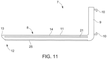
- FIG. 6 shows a fifth embodiment of the load-carrying device 5 or the fork 7, but now in an advantageous side view.
- the fork blade 8 is designed in particular according to one of the above exemplary embodiments.
- the fork tip 13 is advantageously assigned a protective element 25, which protects the fork tip 13 from signs of wear.
- the protective element 25 is arranged on the underside of the fork blade 8 facing away from the top and has a significantly higher abrasion resistance compared to the longitudinal beam 14, depending on the tribology, so that in the event that the fork blade 8 reaches the ground with the free end 12 , in particular while the transport vehicle 1 moves the load-carrying device 5.
- the protective element 25 is optionally formed by one or both of the outer fittings or support elements 15, 16.
- Preferably is it made of stainless steel.
- it is optionally provided that it extends over the entire or almost entire length of the longitudinal beam 14.
- the protective element 25 is also arranged on the underside of the load-carrying device 5 or the fork 7 facing the ground. It extends from the fork tip 13 to the area of the fork bend, so that the fork tine 7 is protected overall against wear caused by contact with the ground.
- the protective element 25 can also be arranged only in the area adjacent to the fork bend. The protective element advantageously extends only over a section of the underside. Arranging the protective element in this area makes sense because this area of the load-carrying device 5 or the fork 7 often comes into contact with the ground when it is picked up or set down and therefore a high level of wear occurs in this area.
- the core element 21 can be made in one piece from a very stable material such as steel or stainless steel and can be surrounded by the longitudinal beam 14 made of plastic. If, in such a configuration, one or more protective elements 25 are arranged on the underside of the load-carrying device 5 facing the ground, these can also be screwed to the load-carrying device 5. A reliable hold is guaranteed by the stability of the core element 21.
- This design makes it possible in a particularly simple manner to remove one or more worn protective elements 25 by loosening the screw connection and to install new protective elements 25. Such a solution requires little effort when replacing the elements and is particularly sustainable because the load-carrying device 5 as such can continue to be used unchanged.
- the fork back 9 has an insertion recess 26 at its lower end, which has an inner contour that at least essentially corresponds to the outer contour of the fork blade 8 at the end 27 facing away from the fork tip 13.
- the fork blade 8 is inserted and inserted into the receiving recess 26 with an insertion section at its end 27 and is thereby positively connected to the fork back 9.
- releasable fastening means 28 are also available, by means of which a user can lock the fork blade 8 on the fork back 9 in the inserted state or release it from it. This makes it possible to easily replace the fork blade 8, for example in the event of signs of wear or damage.
- the transport vehicle 1 has several load-carrying devices available, for example a load-carrying device system, which, however, differ from one another in particular in their length or nature with regard to the support elements 17.
- a load-carrying device system which, however, differ from one another in particular in their length or nature with regard to the support elements 17.
- the load-carrying devices of the load-carrying device system have in common that their ends 27 are designed the same in order to cooperate with the insertion recess 26 as described above.
- the plug connection of the fork blade 8 and the fork back 9 is as in Figure 6 shown, made possible with little additional effort.
- the outer contour of the fork blade 8 at the end 27 and the inner contour of the receiving recess 26 are designed such that the fork blade 8 is held in the receiving recess 26 in a form-fitting manner and in particular without play or almost without play. This ensures precise guidance of the fork blade(s) 8 by means of the transport vehicle 1.
- a sensor 32 in particular, is installed on the fork tip 13 or in the fork back 9 a camera sensor is arranged, which is connected to a control device of the transport vehicle 1 using at least one connection cable guided through one of the through channels 22.
- a display or a screen is arranged in the transport vehicle 1, by means of which the driver or user of the transport vehicle 1 can monitor the camera image captured by the sensor 32 and take it into account for controlling the transport vehicle 1.
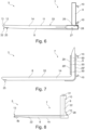
- the sixth exemplary embodiment according to Figure 7 differs from the previous exemplary embodiment essentially in that the fork blade 8 and fork back 9 are formed in one piece with one another.
- the longitudinal beam 14 preferably also extends into or through the fork back 9.
- an optional support element 15, 16, 17 extends through the fork carrier 8 into the fork back 9.
- the fork tip 13 is also advantageously assigned a protective element 25, which protects the fork tip 13 from signs of wear.
- the load-carrying device 5 has a support element 29 on the fork back 9, which essentially surrounds the fork back 9 and partially supports the fork blade 8, at least on its underside.
- the carrier element 29 has the aforementioned fastening hooks 10 for mounting the load-carrying device 5 on the fork carriage of the transport vehicle 1.
- the carrier element 29 is preferably designed in several parts, in particular in two parts.
- the carrier element 29 according to the present exemplary embodiment has a first part 29 ', which is arranged on the front of the fork back 9 facing the fork blade 8, and a second part 29", which is arranged on the back of the fork back 9 facing away from the fork blade .
- the part 29" assigned to the back has a curvature at its lower end, which engages under the fork blade 8 in order to support it from below.
- part of the carrier element 29 can also be cast or laminated into the fork back 9 on the inside.
- Figure 8 shows a seventh embodiment of the load-carrying device 5, in which the through channel 22 extends not only through the fork blade 8, but also through the fork back 9. Alternatively, the through channel 22 can also begin in the area of the fork hook 10.
- the fork blade 8 has the above-mentioned fire extinguishing device 40 on the fork tip 13, which is connected to the through-channel 22 and can be supplied with a fire extinguishing medium through the through-channel 22.
- the through channel 22 can be connected at its end facing away from the fire extinguishing device 40, in particular on the free top side of the fork back 9, to a supply hose 31 or the like, which leads, for example, to a media tank which is arranged on or on the body 2 of the transport vehicle 1 .
- the fork blade 8 in each of the described exemplary embodiments has an advantageous anti-slip coating 33 on the top of the longitudinal member 14 or the fork blade 8, which forms the transport surface 11.
- the anti-slip coating 35 ensures that the load picked up on the fork blade 8 cannot slip or can only slip with great difficulty.
- Figure 9 shows a further exemplary embodiment of the load-carrying device 5 in a perspective sectional view.
- the fork blade 8 and fork back are preferably formed in one piece with one another.
- the support elements 17 to 20 are each surrounded with plastic. This is in particular each of the internal support elements is laminated into a plastic layer.
- the through channel 22 is also formed between the middle support elements 18, 19.
- the fork tine is also designed in two parts, as in Figure 9 indicated by dashed dividing lines.
- the fork tine is divided in two in the middle, so that the through channel 22 is formed proportionally by both fork tine parts. This enables simple and cost-effective production of the fork 7.
- the load-carrying device proves to be particularly light and low-wear.
- the fork tine consists of a longitudinal beam made of carbon fiber-reinforced plastic (so-called carbon), which has a core element made of wood, which is completely enclosed by the longitudinal beam.
- a support element made of stainless steel is also arranged on the underside of the longitudinal beam.
- the support element can have a substantially U-shaped cross section, so that the longitudinal sides of the longitudinal beam are covered at least in some areas. A particularly high weight saving is achieved if the support element is only located in the area or adjacent to the fork bend.
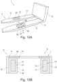
- Figures 10 A and B show an exemplary embodiment of the transport vehicle 1 in training as a pallet truck.
- This essentially differs from the forklift in that it has transport wheels 36 below the respective fork blade 8, which are arranged to be adjustable in height relative to the fork blade 8, in particular in the area of a recess 37 in the fork blade 8, as in the perspective view of Figure 10A shown.
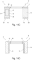
- the respective fork blade 8 has a C- or U-shaped cross section, as in Figure 10B shown, which is a cross-sectional view of the pallet truck along line AA in Figure 10A shows.
- the fork blade 8 has a support element 38 which forms an upper flange which forms the transport surface 11 and has the recess 37.
- Two side legs protrude downwards in one piece from the upper chord, which are arranged at a distance from one another on the long sides of the upper chord and are in particular formed in one piece with it.
- the support element 38 thus encases the underlying longitudinal beam 14 on the top and on the long sides.
- the side legs are designed separately from the upper flange and are formed, for example, by the support elements 15, 16, which are firmly connected to the support elements 38, for example welded, screwed, riveted and / or glued.
- the support elements 15, 16 are made of steel, in particular stainless steel.
- the longitudinal beam also has an opening 39, so that the transport rollers or wheels 36 can lie in the opening.
- the longitudinal beam 14 preferably has two support elements 17, 20 which extend through the longitudinal beam 14 at a distance and at least substantially parallel to one another. The longitudinal beams are so far apart from each other that they extend laterally past the opening 39, so the opening 39 is formed between them, as in Figure 10B shown.
- Figure 10C shows a further exemplary embodiment that differs from the previous exemplary embodiment in that the support elements 15, 16 are not arranged on the side, but at the bottom of the longitudinal beam 14, so that the support elements form underbody protection.
- the support elements 15, 16 in this embodiment correspond to the protective element 25, which extends in particular over the entire length of the longitudinal beam.
- Figure 10C also shows in the drawing plane on the left an exemplary embodiment with a support element 17 as a core element 21 and on the right an exemplary embodiment without a core element 21.
- both sides of the fork blade 8 - in cross section Figure 10C seen - either a core element 21, that is formed from one or more, in particular from a maximum of four, support elements 17 to 20, or no core element 21.
- only one side of the fork blade 8 has a core element 21.
- Figure 10D shows a further exemplary embodiment that differs from the exemplary embodiment of Figure 10B differs in particular in that the support elements 15, 16 are arranged on the inside of the longitudinal beam 14.
- the plastic of the longitudinal beam 14 thus covers the support elements on the top and on the outer side surfaces.
- the longitudinal beam itself also forms the transport surface 11.
- the support elements 15, 16 can also be arranged on the outside of the longitudinal beam 14.
- the respective support element 15 to 20, 38 is preferably welded, cast, laminated, screwed, riveted and/or glued to the respective longitudinal beam 14 in order to ensure a permanently strong connection.
- the longitudinal beam 14 is produced by means of a molding process using a die, male mold or nozzle, in which the plastic is introduced into a mold in which at least one support element is arranged, so that the plastic hardens on the support element and thereby forms a permanently fixed connection with it.
- the load-carrying device according to the invention is a multi-component component, a so-called hybrid component.
- the load-carrying device according to the invention can be manufactured using the cold or hot pressing processes already mentioned. Autoclaves can also be used, which are particularly suitable for pressing fiber composite materials.
- the metallic part is first manufactured and formed in a conventional manner.
- the plastic component is then applied. This can be done by injection molding, laminating, etc.
- the plastic is used as an active medium with which various shaped elements can be inserted into the sheet metal under pressure.
- the hardening of the component can be done, for example, by supplying heat, time and pressure, for example at 80 ° C to 400 ° C in a time of 1 minute to 2,880 minutes.
Landscapes
- Engineering & Computer Science (AREA)
- Transportation (AREA)
- Structural Engineering (AREA)
- Civil Engineering (AREA)
- Life Sciences & Earth Sciences (AREA)
- Geology (AREA)
- Mechanical Engineering (AREA)
- Forklifts And Lifting Vehicles (AREA)
Applications Claiming Priority (2)
| Application Number | Priority Date | Filing Date | Title |
|---|---|---|---|
| DE102021209678 | 2021-09-02 | ||
| PCT/EP2022/074458 WO2023031404A1 (de) | 2021-09-02 | 2022-09-02 | Lastaufnahmemittel, insbesondere gabelzinken |
Publications (3)
| Publication Number | Publication Date |
|---|---|
| EP4172099A1 EP4172099A1 (de) | 2023-05-03 |
| EP4172099B1 true EP4172099B1 (de) | 2024-02-28 |
| EP4172099C0 EP4172099C0 (de) | 2024-02-28 |
Family
ID=83361007
Family Applications (1)
| Application Number | Title | Priority Date | Filing Date |
|---|---|---|---|
| EP22772936.5A Active EP4172099B1 (de) | 2021-09-02 | 2022-09-02 | Lastaufnahmemittel, insbesondere gabelzinken |
Country Status (6)
| Country | Link |
|---|---|
| EP (1) | EP4172099B1 (pl) |
| JP (1) | JP2024532914A (pl) |
| CN (1) | CN117222594A (pl) |
| ES (1) | ES2978564T3 (pl) |
| PL (1) | PL4172099T3 (pl) |
| WO (1) | WO2023031404A1 (pl) |
Family Cites Families (4)
| Publication number | Priority date | Publication date | Assignee | Title |
|---|---|---|---|---|
| DE19515834C1 (de) | 1995-04-29 | 1996-05-23 | Vetter Umformtechnik Gmbh | Gabelzinke |
| US20070170002A1 (en) * | 2006-01-26 | 2007-07-26 | Richard Ziebell | Fork lift attachment, and methods |
| CN211998678U (zh) * | 2020-03-16 | 2020-11-24 | 郑州铁路职业技术学院 | 一种稳固的多方位新型搬运叉车 |
| CN113060490B (zh) * | 2021-03-31 | 2022-08-16 | 昆山精讯电子技术有限公司 | 一种液晶面板搬运小车 |
-
2022
- 2022-09-02 WO PCT/EP2022/074458 patent/WO2023031404A1/de not_active Ceased
- 2022-09-02 JP JP2024514353A patent/JP2024532914A/ja active Pending
- 2022-09-02 CN CN202280031905.8A patent/CN117222594A/zh active Pending
- 2022-09-02 PL PL22772936.5T patent/PL4172099T3/pl unknown
- 2022-09-02 ES ES22772936T patent/ES2978564T3/es active Active
- 2022-09-02 EP EP22772936.5A patent/EP4172099B1/de active Active
Also Published As
| Publication number | Publication date |
|---|---|
| JP2024532914A (ja) | 2024-09-10 |
| EP4172099A1 (de) | 2023-05-03 |
| WO2023031404A1 (de) | 2023-03-09 |
| ES2978564T3 (es) | 2024-09-16 |
| EP4172099C0 (de) | 2024-02-28 |
| PL4172099T3 (pl) | 2024-05-06 |
| CN117222594A (zh) | 2023-12-12 |
Similar Documents
| Publication | Publication Date | Title |
|---|---|---|
| AT520371B1 (de) | Vorrichtung zur Verwendung beim Handhaben einer Last und Verfahren zum Herstellen einer derartigen Vorrichtung | |
| EP2648965B1 (de) | Kraftfahrzeugkarosserie mit versteifungsstreben | |
| EP2360082B1 (de) | Längsträger für ein Fahrgestell und Verfahren für seine Herstellung | |
| EP2593394B1 (de) | Anbauvorrichtung, die an einem hubfahrzeug anzubringen ist, und verfahren zur betätigung | |
| DE102007046868A1 (de) | Transportvorrichtung für Ladungsträger und Verfahren zu deren Steuerung | |
| EP2527231A2 (de) | Achsträger aus Faserwerkstoff verstärktem Kunststoff für Kraftfahrzeuge | |
| DE3880958T2 (de) | Gabeleinheit fuer hubwagen. | |
| DE3113791A1 (de) | "rohrfoermiger hohlkoerper, verfahren zu seiner herstellung sowie vorrichtung zur durchfuehrung des verfahrens" | |
| DE102021118286B4 (de) | Unterbodenschutzelement aus duroplastischem Material, Herstellungsverfahren und Kraftfahrzeug mit einem Unterbodenschutzelement | |
| WO2008125076A1 (de) | Blattfeder aus einem faser-kunststoff-verbundwerkstoff und krafteinleitungselement für dieselbe | |
| DE102018004209B4 (de) | Fahrzeug mit Fahrmodul und Lastmodul | |
| EP4172099B1 (de) | Lastaufnahmemittel, insbesondere gabelzinken | |
| AT503547B1 (de) | Aushärtewerkzeug | |
| DE10312432A1 (de) | Flurförderzeug mit einem Rahmen | |
| EP1698583B1 (de) | Anpassungsfähiges Gleitlager für Teleskopkranausleger | |
| EP4232395B1 (de) | Gabelzinke und logistikfahrzug | |
| DE102014008720A1 (de) | Schwerlastfahrzeug mit Staplerfunktion | |
| DE102011052068A1 (de) | Fördersystem zum Transport von Fahrzeugkarosserien oder Teilen von Fahrzeugkarosserien | |
| EP3144264B1 (de) | Hubvorrichtung | |
| EP2366654B1 (de) | Lenkung eines Portalstaplers | |
| DE202007012787U1 (de) | Spritzgiessmaschine mit zweiteiligem Aufbau | |
| EP4063311B1 (de) | Kranabstützplatte | |
| DE102016121550B3 (de) | Faserverbundbauteil und dessen Herstellung | |
| DE202005015354U1 (de) | Flurförderzeug zum Anheben und Transport von Lasten oder Paletten mit geringer Einfahrhöhe | |
| DE202014004907U1 (de) | Schwerlastfahrzeug mit Staplerfunktion |
Legal Events
| Date | Code | Title | Description |
|---|---|---|---|
| STAA | Information on the status of an ep patent application or granted ep patent |
Free format text: STATUS: UNKNOWN |
|
| STAA | Information on the status of an ep patent application or granted ep patent |
Free format text: STATUS: THE INTERNATIONAL PUBLICATION HAS BEEN MADE |
|
| PUAI | Public reference made under article 153(3) epc to a published international application that has entered the european phase |
Free format text: ORIGINAL CODE: 0009012 |
|
| STAA | Information on the status of an ep patent application or granted ep patent |
Free format text: STATUS: REQUEST FOR EXAMINATION WAS MADE |
|
| 17P | Request for examination filed |
Effective date: 20230130 |
|
| AK | Designated contracting states |
Kind code of ref document: A1 Designated state(s): AL AT BE BG CH CY CZ DE DK EE ES FI FR GB GR HR HU IE IS IT LI LT LU LV MC MK MT NL NO PL PT RO RS SE SI SK SM TR |
|
| GRAP | Despatch of communication of intention to grant a patent |
Free format text: ORIGINAL CODE: EPIDOSNIGR1 |
|
| STAA | Information on the status of an ep patent application or granted ep patent |
Free format text: STATUS: GRANT OF PATENT IS INTENDED |
|
| INTG | Intention to grant announced |
Effective date: 20231103 |
|
| GRAS | Grant fee paid |
Free format text: ORIGINAL CODE: EPIDOSNIGR3 |
|
| GRAA | (expected) grant |
Free format text: ORIGINAL CODE: 0009210 |
|
| STAA | Information on the status of an ep patent application or granted ep patent |
Free format text: STATUS: THE PATENT HAS BEEN GRANTED |
|
| AK | Designated contracting states |
Kind code of ref document: B1 Designated state(s): AL AT BE BG CH CY CZ DE DK EE ES FI FR GB GR HR HU IE IS IT LI LT LU LV MC MK MT NL NO PL PT RO RS SE SI SK SM TR |
|
| DAV | Request for validation of the european patent (deleted) | ||
| DAX | Request for extension of the european patent (deleted) | ||
| REG | Reference to a national code |
Ref country code: GB Ref legal event code: FG4D Free format text: NOT ENGLISH |
|
| REG | Reference to a national code |
Ref country code: CH Ref legal event code: EP |
|
| REG | Reference to a national code |
Ref country code: DE Ref legal event code: R096 Ref document number: 502022000568 Country of ref document: DE |
|
| REG | Reference to a national code |
Ref country code: IE Ref legal event code: FG4D Free format text: LANGUAGE OF EP DOCUMENT: GERMAN |
|
| U01 | Request for unitary effect filed |
Effective date: 20240313 |
|
| U07 | Unitary effect registered |
Designated state(s): AT BE BG DE DK EE FI FR IT LT LU LV MT NL PT SE SI Effective date: 20240322 |
|
| PG25 | Lapsed in a contracting state [announced via postgrant information from national office to epo] |
Ref country code: IS Free format text: LAPSE BECAUSE OF FAILURE TO SUBMIT A TRANSLATION OF THE DESCRIPTION OR TO PAY THE FEE WITHIN THE PRESCRIBED TIME-LIMIT Effective date: 20240628 |
|
| PG25 | Lapsed in a contracting state [announced via postgrant information from national office to epo] |
Ref country code: GR Free format text: LAPSE BECAUSE OF FAILURE TO SUBMIT A TRANSLATION OF THE DESCRIPTION OR TO PAY THE FEE WITHIN THE PRESCRIBED TIME-LIMIT Effective date: 20240529 |
|
| PG25 | Lapsed in a contracting state [announced via postgrant information from national office to epo] |
Ref country code: HR Free format text: LAPSE BECAUSE OF FAILURE TO SUBMIT A TRANSLATION OF THE DESCRIPTION OR TO PAY THE FEE WITHIN THE PRESCRIBED TIME-LIMIT Effective date: 20240228 Ref country code: RS Free format text: LAPSE BECAUSE OF FAILURE TO SUBMIT A TRANSLATION OF THE DESCRIPTION OR TO PAY THE FEE WITHIN THE PRESCRIBED TIME-LIMIT Effective date: 20240528 |
|
| PG25 | Lapsed in a contracting state [announced via postgrant information from national office to epo] |
Ref country code: RS Free format text: LAPSE BECAUSE OF FAILURE TO SUBMIT A TRANSLATION OF THE DESCRIPTION OR TO PAY THE FEE WITHIN THE PRESCRIBED TIME-LIMIT Effective date: 20240528 Ref country code: NO Free format text: LAPSE BECAUSE OF FAILURE TO SUBMIT A TRANSLATION OF THE DESCRIPTION OR TO PAY THE FEE WITHIN THE PRESCRIBED TIME-LIMIT Effective date: 20240528 Ref country code: IS Free format text: LAPSE BECAUSE OF FAILURE TO SUBMIT A TRANSLATION OF THE DESCRIPTION OR TO PAY THE FEE WITHIN THE PRESCRIBED TIME-LIMIT Effective date: 20240628 Ref country code: HR Free format text: LAPSE BECAUSE OF FAILURE TO SUBMIT A TRANSLATION OF THE DESCRIPTION OR TO PAY THE FEE WITHIN THE PRESCRIBED TIME-LIMIT Effective date: 20240228 Ref country code: GR Free format text: LAPSE BECAUSE OF FAILURE TO SUBMIT A TRANSLATION OF THE DESCRIPTION OR TO PAY THE FEE WITHIN THE PRESCRIBED TIME-LIMIT Effective date: 20240529 |
|
| REG | Reference to a national code |
Ref country code: ES Ref legal event code: FG2A Ref document number: 2978564 Country of ref document: ES Kind code of ref document: T3 Effective date: 20240916 |
|
| PG25 | Lapsed in a contracting state [announced via postgrant information from national office to epo] |
Ref country code: SM Free format text: LAPSE BECAUSE OF FAILURE TO SUBMIT A TRANSLATION OF THE DESCRIPTION OR TO PAY THE FEE WITHIN THE PRESCRIBED TIME-LIMIT Effective date: 20240228 |
|
| U20 | Renewal fee for the european patent with unitary effect paid |
Year of fee payment: 3 Effective date: 20240910 |
|
| PG25 | Lapsed in a contracting state [announced via postgrant information from national office to epo] |
Ref country code: CZ Free format text: LAPSE BECAUSE OF FAILURE TO SUBMIT A TRANSLATION OF THE DESCRIPTION OR TO PAY THE FEE WITHIN THE PRESCRIBED TIME-LIMIT Effective date: 20240228 |
|
| PG25 | Lapsed in a contracting state [announced via postgrant information from national office to epo] |
Ref country code: SK Free format text: LAPSE BECAUSE OF FAILURE TO SUBMIT A TRANSLATION OF THE DESCRIPTION OR TO PAY THE FEE WITHIN THE PRESCRIBED TIME-LIMIT Effective date: 20240228 |
|
| PG25 | Lapsed in a contracting state [announced via postgrant information from national office to epo] |
Ref country code: SM Free format text: LAPSE BECAUSE OF FAILURE TO SUBMIT A TRANSLATION OF THE DESCRIPTION OR TO PAY THE FEE WITHIN THE PRESCRIBED TIME-LIMIT Effective date: 20240228 Ref country code: SK Free format text: LAPSE BECAUSE OF FAILURE TO SUBMIT A TRANSLATION OF THE DESCRIPTION OR TO PAY THE FEE WITHIN THE PRESCRIBED TIME-LIMIT Effective date: 20240228 Ref country code: RO Free format text: LAPSE BECAUSE OF FAILURE TO SUBMIT A TRANSLATION OF THE DESCRIPTION OR TO PAY THE FEE WITHIN THE PRESCRIBED TIME-LIMIT Effective date: 20240228 Ref country code: CZ Free format text: LAPSE BECAUSE OF FAILURE TO SUBMIT A TRANSLATION OF THE DESCRIPTION OR TO PAY THE FEE WITHIN THE PRESCRIBED TIME-LIMIT Effective date: 20240228 |
|
| REG | Reference to a national code |
Ref country code: DE Ref legal event code: R097 Ref document number: 502022000568 Country of ref document: DE |
|
| PLBE | No opposition filed within time limit |
Free format text: ORIGINAL CODE: 0009261 |
|
| STAA | Information on the status of an ep patent application or granted ep patent |
Free format text: STATUS: NO OPPOSITION FILED WITHIN TIME LIMIT |
|
| 26N | No opposition filed |
Effective date: 20241129 |
|
| PG25 | Lapsed in a contracting state [announced via postgrant information from national office to epo] |
Ref country code: MC Free format text: LAPSE BECAUSE OF FAILURE TO SUBMIT A TRANSLATION OF THE DESCRIPTION OR TO PAY THE FEE WITHIN THE PRESCRIBED TIME-LIMIT Effective date: 20240228 |
|
| PG25 | Lapsed in a contracting state [announced via postgrant information from national office to epo] |
Ref country code: IE Free format text: LAPSE BECAUSE OF NON-PAYMENT OF DUE FEES Effective date: 20240902 |
|
| U20 | Renewal fee for the european patent with unitary effect paid |
Year of fee payment: 4 Effective date: 20250729 |
|
| REG | Reference to a national code |
Ref country code: CH Ref legal event code: U11 Free format text: ST27 STATUS EVENT CODE: U-0-0-U10-U11 (AS PROVIDED BY THE NATIONAL OFFICE) Effective date: 20251001 |
|
| PGFP | Annual fee paid to national office [announced via postgrant information from national office to epo] |
Ref country code: TR Payment date: 20250829 Year of fee payment: 4 Ref country code: PL Payment date: 20250820 Year of fee payment: 4 |
|
| PGFP | Annual fee paid to national office [announced via postgrant information from national office to epo] |
Ref country code: CH Payment date: 20251001 Year of fee payment: 4 |
|
| PG25 | Lapsed in a contracting state [announced via postgrant information from national office to epo] |
Ref country code: CY Free format text: LAPSE BECAUSE OF FAILURE TO SUBMIT A TRANSLATION OF THE DESCRIPTION OR TO PAY THE FEE WITHIN THE PRESCRIBED TIME-LIMIT; INVALID AB INITIO Effective date: 20220902 |
|
| PGFP | Annual fee paid to national office [announced via postgrant information from national office to epo] |
Ref country code: ES Payment date: 20251020 Year of fee payment: 4 |
|
| PG25 | Lapsed in a contracting state [announced via postgrant information from national office to epo] |
Ref country code: HU Free format text: LAPSE BECAUSE OF FAILURE TO SUBMIT A TRANSLATION OF THE DESCRIPTION OR TO PAY THE FEE WITHIN THE PRESCRIBED TIME-LIMIT; INVALID AB INITIO Effective date: 20220902 |