EP4172099B1 - Load-receiving means, in particular fork prongs - Google Patents
Load-receiving means, in particular fork prongs Download PDFInfo
- Publication number
- EP4172099B1 EP4172099B1 EP22772936.5A EP22772936A EP4172099B1 EP 4172099 B1 EP4172099 B1 EP 4172099B1 EP 22772936 A EP22772936 A EP 22772936A EP 4172099 B1 EP4172099 B1 EP 4172099B1
- Authority
- EP
- European Patent Office
- Prior art keywords
- fork
- load
- receiving means
- means according
- previous
- Prior art date
- Legal status (The legal status is an assumption and is not a legal conclusion. Google has not performed a legal analysis and makes no representation as to the accuracy of the status listed.)
- Active
Links
- 229920003023 plastic Polymers 0.000 claims description 68
- 239000004033 plastic Substances 0.000 claims description 68
- 239000000463 material Substances 0.000 claims description 24
- 229910052751 metal Inorganic materials 0.000 claims description 17
- 239000002184 metal Substances 0.000 claims description 17
- 230000001681 protective effect Effects 0.000 claims description 15
- 239000002023 wood Substances 0.000 claims description 15
- 238000013461 design Methods 0.000 claims description 13
- 238000003780 insertion Methods 0.000 claims description 8
- 230000037431 insertion Effects 0.000 claims description 8
- 229920002430 Fibre-reinforced plastic Polymers 0.000 claims description 5
- 239000011151 fibre-reinforced plastic Substances 0.000 claims description 5
- 239000007788 liquid Substances 0.000 claims description 5
- 238000000354 decomposition reaction Methods 0.000 claims description 3
- 229910010293 ceramic material Inorganic materials 0.000 claims description 2
- 239000003365 glass fiber Substances 0.000 claims description 2
- 238000000137 annealing Methods 0.000 claims 1
- 238000000748 compression moulding Methods 0.000 claims 1
- 238000004519 manufacturing process Methods 0.000 description 11
- 229910000831 Steel Inorganic materials 0.000 description 9
- 229910001220 stainless steel Inorganic materials 0.000 description 9
- 239000010935 stainless steel Substances 0.000 description 9
- 239000010959 steel Substances 0.000 description 9
- 239000004918 carbon fiber reinforced polymer Substances 0.000 description 6
- 238000011161 development Methods 0.000 description 6
- 238000000034 method Methods 0.000 description 5
- 238000005299 abrasion Methods 0.000 description 4
- 239000004744 fabric Substances 0.000 description 4
- 239000000835 fiber Substances 0.000 description 4
- 229920001187 thermosetting polymer Polymers 0.000 description 4
- VYPSYNLAJGMNEJ-UHFFFAOYSA-N Silicium dioxide Chemical compound O=[Si]=O VYPSYNLAJGMNEJ-UHFFFAOYSA-N 0.000 description 3
- 229910052799 carbon Inorganic materials 0.000 description 3
- 239000000919 ceramic Substances 0.000 description 3
- 239000002131 composite material Substances 0.000 description 3
- 238000012986 modification Methods 0.000 description 3
- 230000004048 modification Effects 0.000 description 3
- 239000007787 solid Substances 0.000 description 3
- OKTJSMMVPCPJKN-UHFFFAOYSA-N Carbon Chemical compound [C] OKTJSMMVPCPJKN-UHFFFAOYSA-N 0.000 description 2
- 229920000049 Carbon (fiber) Polymers 0.000 description 2
- 239000004760 aramid Substances 0.000 description 2
- 229920003235 aromatic polyamide Polymers 0.000 description 2
- 239000004917 carbon fiber Substances 0.000 description 2
- 239000011111 cardboard Substances 0.000 description 2
- 239000011248 coating agent Substances 0.000 description 2
- 238000000576 coating method Methods 0.000 description 2
- 239000011152 fibreglass Substances 0.000 description 2
- 239000006260 foam Substances 0.000 description 2
- 239000011521 glass Substances 0.000 description 2
- 238000007731 hot pressing Methods 0.000 description 2
- 238000001746 injection moulding Methods 0.000 description 2
- 230000010354 integration Effects 0.000 description 2
- 238000002844 melting Methods 0.000 description 2
- 230000008018 melting Effects 0.000 description 2
- 238000003825 pressing Methods 0.000 description 2
- 239000004576 sand Substances 0.000 description 2
- 239000000243 solution Substances 0.000 description 2
- 239000004575 stone Substances 0.000 description 2
- 229920001169 thermoplastic Polymers 0.000 description 2
- 239000004416 thermosoftening plastic Substances 0.000 description 2
- 238000012549 training Methods 0.000 description 2
- 229920000271 Kevlar® Polymers 0.000 description 1
- VVQNEPGJFQJSBK-UHFFFAOYSA-N Methyl methacrylate Chemical compound COC(=O)C(C)=C VVQNEPGJFQJSBK-UHFFFAOYSA-N 0.000 description 1
- 229920005372 Plexiglas® Polymers 0.000 description 1
- 239000006004 Quartz sand Substances 0.000 description 1
- 238000004026 adhesive bonding Methods 0.000 description 1
- 229910052782 aluminium Inorganic materials 0.000 description 1
- XAGFODPZIPBFFR-UHFFFAOYSA-N aluminium Chemical compound [Al] XAGFODPZIPBFFR-UHFFFAOYSA-N 0.000 description 1
- 239000004568 cement Substances 0.000 description 1
- 239000003795 chemical substances by application Substances 0.000 description 1
- 239000004567 concrete Substances 0.000 description 1
- 239000002826 coolant Substances 0.000 description 1
- 238000005260 corrosion Methods 0.000 description 1
- 230000007797 corrosion Effects 0.000 description 1
- 238000005520 cutting process Methods 0.000 description 1
- 230000005489 elastic deformation Effects 0.000 description 1
- 229920001971 elastomer Polymers 0.000 description 1
- 239000000806 elastomer Substances 0.000 description 1
- 230000007613 environmental effect Effects 0.000 description 1
- 239000008187 granular material Substances 0.000 description 1
- 238000002347 injection Methods 0.000 description 1
- 239000007924 injection Substances 0.000 description 1
- 239000004761 kevlar Substances 0.000 description 1
- 238000010030 laminating Methods 0.000 description 1
- 238000003475 lamination Methods 0.000 description 1
- 239000011159 matrix material Substances 0.000 description 1
- VNWKTOKETHGBQD-UHFFFAOYSA-N methane Chemical compound C VNWKTOKETHGBQD-UHFFFAOYSA-N 0.000 description 1
- 238000003801 milling Methods 0.000 description 1
- 238000000465 moulding Methods 0.000 description 1
- 239000000123 paper Substances 0.000 description 1
- 230000002265 prevention Effects 0.000 description 1
- 239000002990 reinforced plastic Substances 0.000 description 1
- 239000011347 resin Substances 0.000 description 1
- 229920005989 resin Polymers 0.000 description 1
- 238000000926 separation method Methods 0.000 description 1
- 239000007921 spray Substances 0.000 description 1
- 239000003351 stiffener Substances 0.000 description 1
- 238000003860 storage Methods 0.000 description 1
- 238000005303 weighing Methods 0.000 description 1
- 210000002268 wool Anatomy 0.000 description 1
Images


Classifications
-
- B—PERFORMING OPERATIONS; TRANSPORTING
- B66—HOISTING; LIFTING; HAULING
- B66F—HOISTING, LIFTING, HAULING OR PUSHING, NOT OTHERWISE PROVIDED FOR, e.g. DEVICES WHICH APPLY A LIFTING OR PUSHING FORCE DIRECTLY TO THE SURFACE OF A LOAD
- B66F9/00—Devices for lifting or lowering bulky or heavy goods for loading or unloading purposes
- B66F9/06—Devices for lifting or lowering bulky or heavy goods for loading or unloading purposes movable, with their loads, on wheels or the like, e.g. fork-lift trucks
- B66F9/075—Constructional features or details
- B66F9/12—Platforms; Forks; Other load supporting or gripping members
Definitions
- the invention relates to a load-carrying device, in particular forks for a forklift or pallet truck, with at least one elongated fork blade, which has a transport surface for receiving transported goods and a fork tip at a first end that is free in the longitudinal extension and is designed in several parts. Furthermore, the invention relates to a transport vehicle, in particular a forklift or pallet truck, with a vehicle body and with at least one load-carrying device, in particular forks, which is arranged in particular displaceably on the vehicle body and which is designed as described above.
- Load-carrying devices and transport vehicles of the type mentioned are already known from the prior art.
- the fork back can be attached to a fork carrier of a transport vehicle.
- the fork blade consists of a plurality of individual discs lying next to one another, which are held so that they cannot be moved relative to one another and each have the full contour of the fork tine in a side view.
- intermediate disks or segments made of plastic can be arranged in the area of the fork back, which serve to insulate noise.
- CN 211 998 678 U discloses the preamble of claim 1.
- the invention is based on the object of creating an improved load-carrying device, through which in particular the weight of the load-carrying device is reduced, and in particular without the mechanical properties or the load-carrying capacity of the load-carrying device being reduced.
- the object on which the invention is based is achieved by a load-carrying device with the features of claim 1.
- This has the advantage that the weight of the fork blade is reduced by a simple measure in a cost-effective and energy-saving manner.
- the fork blade has a longitudinal beam made of plastic, which extends at least substantially along the entire fork blade in its longitudinal extent. This also increases the corrosion resistance of the fork blade.
- the fork blade can therefore be partially made of plastic, with the fact that the plastic extends at least substantially along the entire fork blade meaning that a large part of the fork blade can now be made of plastic. This reduces the weight of the fork blade, which is otherwise often made of metal.
- the weight is reduced by approximately 25% to 90%, in particular 35% to 50%, compared to conventional fork blades made of metal.
- the fork blade according to the invention also has at least one support element made of a material with a wear resistance that is higher than that of the longitudinal member or the plastic. Wear resistance in the sense of the present invention refers in particular to abrasion resistance.
- the design of the load-carrying device according to the invention has the advantage that the load-carrying device can also be used in situations in which conventional steel forks cannot be used or can only be used to a limited extent.
- forks made of stainless steel are used.
- these are relatively expensive to produce and, depending on tribology and friction, can still tend to produce sparks.
- Through the inventive Training ensures that flying sparks are avoided cost-effectively. It is sufficient that, for example, externally attached support elements in the form of external fittings are made of stainless steel. Because only a small part of the load-carrying device is made of stainless steel, the overall manufacturing costs are lower.
- the present invention also has the advantage that the plastic only causes elastic deformation of the fork blade at high loads, especially if a fiber-reinforced plastic is used as the plastic. In contrast, metal fork blades fatigue, causing them to permanently bend and become unusable. As a result, the invention achieves a longer service life for the load-carrying device.
- the load-carrying device is in particular permanently installed or can be installed on a transport vehicle, or is designed in such a way that it can be detachably attached to a transport vehicle, in particular interchangeably.
- the load-carrying means has two fork blades, which are designed as described above and are in particular arranged parallel to one another and spaced apart from one another, so that their transport surfaces lie at least essentially in a common transport surface plane.
- the two fork blades are preferably arranged or held on a common fork back.
- the plastic of the longitudinal beam preferably has a density in the range of 600 kg/m 3 to 3,000 kg/m 3 or 0.6 to 3.0 g/cm 3 , particularly preferably a density of 1,400 kg/m 3 to 2,100 kg/ m 3 or 1.2 to 2.5 g/cm 3 . Furthermore, the plastic preferably has an elongation at break A of 0.2 to 8.1% and a curing temperature of 20 ° C to 700 ° C.
- the longitudinal beam preferably has a tensile strength of 1,500 N/mm 2 to 30,000 N/mm 2 , preferably of 2,000 N/mm 2 to 5,000 N/mm 2 .
- the at least one support element has a density in a range of 4,500 kg/m 3 to 8,900 kg/m 3 and a tensile strength of 300 N/mm 2 to 1,450 N/mm, particularly when it is made of metal on the outside or inside of the longitudinal beam 2 , an elongation at break A of 10% to 55% and a Melting temperature of 500°C to 5,500°C.
- the support element is made of materials other than metal, in particular when attached in or on the longitudinal beam, this material has a density of 150 kg/m 3 to 4,000 kg/m 3 , a tensile strength of 10 N/mm 2 to 30,000 N/mm 2 and an elongation at break A of 0.2% to 900% and a decomposition temperature or hardening temperature of -20°C to 1,000°C.
- the longitudinal member is made of a fiber-reinforced plastic, in particular of glass fiber or carbon fiber reinforced plastic.
- the robustness or resilience of the longitudinal member itself is further increased in an advantageous manner, without the weight of the fork blade receiving a significant increase in weight.
- the longitudinal beam is made from several layers of fiber-reinforced plastic, with the fiber orientation of adjacent layers preferably being different in order to further increase the stability of the longitudinal beam.
- the longitudinal beam is in particular laminated, extruded, pressed, injection molded, vulcanized, layered, loaded, vacuum pressed and/or vacuum drawn.
- the at least one support element extends as a core element in the longitudinal extent of the fork blade and is at least essentially surrounded by the plastic on the circumference.
- the core element is covered or surrounded by the plastic on at least one of its - when used as intended - in particular vertical long sides and / or on its at least essentially horizontal top side.
- the support element is thus arranged integrated into the fork blade or into the longitudinal beam, so that it forms a core of the fork blade. Because the support element is surrounded by the plastic on the circumference, i.e. seen in cross section, the support element is arranged in a protected manner inside the longitudinal beam.
- the core element and/or the at least one support element is made of wood, plastic, metal, sand, stone, cardboard, foam fabric, granules, glass, wool or ceramic.
- the metal version ensures a particularly high screw strength for external and/or internal fittings of the fork blade
- the wooden version offers the advantage that the core element itself is also weight-saving and thus further reduces the weight of the fork blade.
- the core element, in particular the wooden core serves as a support for the plastic of the longitudinal member and is inexpensive and sustainable to produce, since the shape of the core element can be designed at least essentially independently of the shape of the fork blade itself.
- the core element can have a square, circular, oval, polygonal or even triangular cross-section without thereby affecting the shape of the fork blade, particularly in the area of its transport surface.
- the at least one support element is also made of a plastic, but then of a plastic material that differs from the material properties of the longitudinal member.
- the core element has at least two support elements which extend parallel to one another and are surrounded together by the plastic. Two support elements thus form the core element of the fork blade, which are enclosed or combined by the plastic. The support elements are held together by the plastic and contribute to the robustness and cost-effectiveness of the production of the fork blade.
- the choice and number of support elements, in particular the core element allows the fork blade to be adapted to different boundary conditions, such as different expected weight classes of the transported goods adaptable, so that, for example, the fork blade can be advantageously adapted to different loads with constant external dimensions by choosing the core element or elements in terms of number and material.
- the support elements in the plastic preferably lie directly against one another, so that they can be easily cast or encased by the plastic during production, for example.
- the core element has more than two, for example three or four, support elements.
- At least two support elements are made from the same or different materials.
- the load capacity of the fork blade and its total weight can be further influenced.
- the materials are preferably chosen such that the combination of materials results in advantageous mechanical properties for the core element.
- the longitudinal beam, the support element and/or the core element are preferably designed to be solid, in one piece or in several parts. If the core element has a plurality of support elements, these are preferably each solid and lie against one another in order to form an at least essentially closed cross section. This results in a particularly high load-bearing capacity of the load-carrying device.
- the support element, the core element and/or the longitudinal beam have at least one through-channel for guiding a gaseous or liquid medium and/or at least one connecting cable.
- the core element is provided, for example, with a bore or a bore channel, in particular in the longitudinal extent.
- the at least one or at least one support element is preferably designed as a hollow element, for example as a tube, in particular made of steel or wood, with a circular, rectangular or polygonal cross section.
- the hollow design of the support element or the provision of the through channel further reduces the weight of the core element, so that the weight of the fork blade also further reduces is reduced.
- the support elements of the core element are arranged and designed in such a way that they form at least one through-channel between them.
- the support elements themselves are preferably solid.
- the design of the through channel for guiding a gaseous or liquid medium for example a cooling medium, fire extinguishing medium or the like, or an electrical connecting cable, which is connected to a sensor, weighing or camera device, for example in the area of the fork tip, the fork blade or the fork back, increases the possible uses of the advantageous load-carrying device.
- the inventive design of the fork tine enables cost-effective integration of the through channel into the fork blade.
- the through channel is formed by a tubular element which extends through the support element or one of the support elements but is designed as a separate component.
- a metal tube in particular an aluminum tube, is inserted, which forms the through-channel.
- the tubular element is inserted in particular into a bore or corresponding through opening in the support element.
- the through channel leads to a fire extinguishing device that can be controlled in particular, which is arranged in particular at an end of the fork blade facing away from the fork back or fork bend and, for example, has a spray nozzle by means of which a fire extinguishing agent conveyed through the through channel can be sprayed out.
- the respective support element is made of wood. It has been found that wood offers the fork blade a high level of stability, which in many cases is sufficient, and is inexpensive to produce.
- the support element each has a square cross section. This results, on the one hand, in cost-effective production and, on the other hand, in simple use in the fork blade. In particular, this also results in scalability because the use of several stiffening elements increases the load capacity of the fork blade of the fork blade can be individually adjusted with little effort by arranging support elements with the same square cross-section next to one another, with the number and material of the support elements being selectable.
- the core element particularly preferably has one, two, three, four, five or six support elements which rest against one another in at least one row or are adjacently surrounded by the plastic. This results in an advantageous package of support elements through which the fork blade achieves the desired load capacity.
- the support elements preferably have the same cross section. This reduces the variety of parts and simplifies production. Alternatively, at least two of the support elements have different cross sections. If there are several support elements, they are preferably made of the same material. Optionally, at least two of the support elements are made of different materials.
- the at least one support element is arranged as an external fitting on the longitudinal beam.
- the support element is therefore not integrated into the longitudinal beam, but is arranged on the outside of it.
- the support element not only acts as an internal stiffener, but also as an external protective element, which in particular protects the plastic of the longitudinal member from external influences, such as the separation of fibers in the food industry.
- the support element is arranged on the - when used as intended - at least essentially vertical or horizontal longitudinal sides of the longitudinal member or of the fork blade and extends along the longitudinal sides at least to the fork tip. As a result, the long sides of the fork blade are advantageously protected and sealed by the support element.
- the supporting element is preferably made of metal as an external fitting. This reduces wear and abrasion on the fork blade.
- the support element is made in particular from steel, preferably stainless steel.
- the outer fitting is also made of plastic or food-safe materials, which, however, differs from the plastic of the longitudinal beam.
- the outer fitting forms the transport surface of the fork blade with or as a whole. This ensures that the plastic of the longitudinal beam is not directly impacted by the transported goods. This reduces wear on the fork blade.
- the support element assigned to a long side projects, for example, in areas over the top and / or bottom of the longitudinal beam, so that the transported goods cannot rest directly on the plastic or come into contact with the plastic.
- the outer fitting is designed such that it extends over the top of the longitudinal beam to form the transport surface or a transport surface section.
- the respective support element is designed as an outer fitting U or C-shaped in cross section, so that it has two side legs and a base section, from which the side legs protrude in particular vertically.
- the side legs are in particular designed in such a way that they cover the sides of the fork blade or the longitudinal beam at least in some areas, while the base section rests on the long side of the fork blade or the longitudinal beam.
- the support element can be designed as an external fitting I- or L-shaped in cross section. Each of the designs mentioned ensures a particularly secure locking of the support element on the longitudinal beam. In addition, this offers the advantage that the support element itself forms or helps form the transport surface of the fork blade on the top of the longitudinal member.
- a very big advantage is the sustainability and thus the environmental friendliness of the solution according to the invention, since the external support elements have to be replaced if there is wear of 10% of the cross section in accordance with the accident prevention regulation ISO 5057 and this can be done individually and therefore more easily according to the invention.
- the fork blade is preferably connected to a fork back, in particular formed in one piece with the fork back.
- the longitudinal beam extends into the back of the fork, so that the advantages and design variants mentioned above also arise for the back of the fork.
- the fork blade has an insertion section at its end facing away from the fork tip for insertion into a plug-in receptacle of a fork back of the fork tine.
- the fork back has, for example, holding means for locking the fork tine on a transport vehicle.
- the holding means are, for example, retaining bolts, hooks, projections and/or receptacles.
- the plug-in receptacle has a cross section which corresponds at least substantially to the cross-section of the fork blade on the insertion section, so that the fork blade can be inserted into the plug-in receptacle in a form-fitting manner and with almost no play or play.
- a locking means is available, through which the fork blade can be captively secured to the fork back, in particular releasably fastened, so that unwanted detachment of the fork blade from the fork back is prevented at any time.
- the longitudinal support has at least one recess in which a sensor, in particular a weight sensor, temperature sensor, distance sensor or a camera device is arranged in the fork blade or fork back.
- the sensor increases the functionality of the load-carrying device.
- the advantageous design of the longitudinal beam made of plastic means that one or more recesses for one or more sensors can be introduced cost-effectively, especially subsequently.
- the recess particularly preferably has an opening to the through-channel in order to enable simple wiring of the sensor.
- the respective support element is cast, screwed, riveted, glued and/or laminated to the respective longitudinal beam.
- the plastic is produced or processed by a loading process, and in particular hardened by temperature and pressure in a mold, in which optionally there is also at least one support element, so that the plastic is advantageously molded onto the support element.
- the transport vehicle is an industrial truck that is motorized or hand-guided.
- the transport vehicle is preferably a forklift or a hand-held pallet truck.
- the forklift truck in particular has a fork carrier to which the fork tines can be attached.
- the fork tine is permanently installed on the body of the pallet truck, for example.
- the load-carrying device is designed for use on a pallet truck, it preferably has at least one impeller, in particular one or two transport rollers, which are rotatably mounted on the fork blade in the area of the front end of the fork blade.
- the storage preferably has means for raising and lowering the fork blade, or for changing the vertical position of the impeller in relation to the fork blade.
- Figure 1 shows a simplified representation of a transport vehicle 1, which is designed as a forklift according to the present exemplary embodiment.
- the transport vehicle 1 has a body 2, which is carried by a chassis 3, which has a plurality of wheels, of which preferably at least two are connected to a drive device as drive wheels, and of which at least two are steerable and connected to a steering device, and a holding device 4 for an advantageous load-carrying device 5
- the lifting device 4 has a mast 6 on which a fork carriage - not shown - can be stored so that it can be moved in height.
- the mast and the fork carriage are usually made of metal Usually made of steel. However, it is also possible to make the mast and fork carrier from carbon fiber reinforced plastic to save weight.
- the load-carrying device 5, here in the form of a fork tine 7, is attached, hung or can be releasably attached to the fork carrier.
- the load-carrying device 5 can be adjusted in height and/or width by means of the fork carriage in order to pick up or put down transport goods.
- the forklift 1 preferably has two of the load-carrying devices 5 or a load-carrying device 5 with two fork blades 8, as described below, which are attached to the fork carriage parallel to one another.
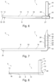
- Figure 2 shows a perspective view of the load-carrying device 5 in the form of the fork 7.
- the fork 7 has a fork blade 8 and a fork back 9.
- the fork blade 8 and the fork back 9 are aligned at an angle of 90 ° or almost 90 ° to one another, so that at When used as intended, the fork blade 8 is aligned essentially horizontally and the fork back 9 is aligned vertically, so that a fork bend is formed between the fork blade 8 and the fork back 9.
- the fork back 9 has protruding hooks 10 on its rear side facing away from the fork blade for attachment to the fork carrier.
- the fork back 9 and the fork blade 8 are firmly connected to one another, in this case in one piece.
- the fork blade 8 has a transport surface 11 on its top side, i.e. the side facing the fork back 9, which serves to hold transport goods on the fork blade 8.
- the transport surface 11 is either continuous on the top of the fork blade 8 or interrupted.
- the fork blade 8 also has a fork tip 13. With the fork tip 13, the fork tine 7 can be moved under a transport item, with the fork tip 13 making it easier to thread the fork blade 8 into, for example, receiving openings on a pallet or the like.
- the fork tip 13 is, for example, as in Figure 2 shown, at least partially tapered.
- the fork blade 8 has a longitudinal member 14 made of plastic, which extends from the fork back 9 to the fork tip 13 and thus over the entire length of the fork blade 8 extends longitudinally.
- the plastic longitudinal member 14 preferably also extends through the fork back 9.
- the plastic is in particular glass fiber or carbon fiber reinforced plastic.
- carbon fiber-reinforced plastic, so-called carbon has proven successful here.
- plastics refer to carbon fibers that lie in one or different directions in the plastic. It is an anisotropic material.
- the fibers can, for example, be constructed unidirectionally, bidirectionally, unimpregnated, triaxially, quadraxially, multiaxially or through fabric inserts or fabric prepregs.
- the matrix consists of thermoset or thermoplastic. The plastics mentioned ensure high resilience and low weight of the forks.
- the support elements 15, 16 are external fittings of the fork 7, which are each designed to follow the L shape of the fork 7 along a side surface of the fork 7.
- the outer fittings include the longitudinal beam 14 on its long sides in a C or U shape, so that the outer fittings or the support elements 16, 15 themselves form the transport surface 11 of the fork blade 8 and direct contact of the transported goods with the plastic of the longitudinal beam 14 is prevented.
- Figure 2 shows an enlarged detailed sectional view of the support element 15 in circle A.
- the outer fitting has a base section from which two side legs protrude laterally, which are arranged parallel and spaced apart from one another. One of the side legs rests on the top of the longitudinal beam 14 and the other of the side legs rests on the underside of the longitudinal beam 14.
- the support element 15 at least partially forms the transport surface 11 and an underbody protection for the fork arms 7.
- the support elements 15, 16 are in particular at least in some areas from the longitudinal beam 14 upwards or in the direction of the fork back 9.
- the support elements are rectangular in cross section, as in circle A of Figure 2 indicated by dashed lines.
- the support elements 15, 16 thus rest laterally on the longitudinal beam 14 and are connected to it in particular by introducing resin, screwing, gluing and/or riveting.
- the longitudinal beam 14 can also be cast onto the support elements 15, 16, for example by an injection molding process with a mold, in which the support elements 15, 16 are first placed and the plastic is then filled and hardened.
- the plastic is treated by lamination, loading.
- the support elements 15, 16 are arranged solely on the underside of the fork 7 facing the ground.
- only one support element can be used in this embodiment.
- the support elements 15, 16 or the support element can only extend in the area of the fork bend or immediately adjacent to it on the underside of the fork, since this area is subject to the greatest wear when picking up loads and placing loads down. This is due to the fact that the forklift is often still in motion when the fork is raised and lowered, so that the area adjacent to the fork bend can drag on the ground, which leads to increased wear in the form of abrasion. This is counteracted by attaching the support elements 15, 16 in the area mentioned.
- the support elements 15, 16 are made of a material that has higher strength and less wear compared to the longitudinal beam 14.
- the support elements 15, 16 are in particular made of a material with increased strength compared to plastic, such as metal, in particular steel or stainless steel, or made from a ceramic material.
- the load-carrying device 5, in particular the fork blade 8 is therefore designed in several parts in the manner of a composite component and combines low weight with high resilience.
- the permissible transport weight of the transport vehicle 1 is advantageously increased by the reduced weight of the load-carrying device 5 and thus the efficiency of the transport vehicle 1 is improved.
- the fork blade has at least one internal support element, as described below with reference to the other figures, through which the load capacity of the longitudinal beam is advantageously increased and the manufacturing costs are reduced.
- the materials of the support elements 15, 16 and the longitudinal beam 14 differ in their density, elongation at break and temperature resistance.
- the materials have the following properties or values:
- the density is 600 to 3,000 kg/m 3 , preferably 1,400 to 2,100 kg/m 3 .
- the tensile strength is 1,500 to 30,000 N/mm 2 , preferably 2,000 to 5,000 N/mm 2 .
- the deformation or hardening temperature is between 20 and 700°C with a cycle time of 1 to 10,080 minutes, while the elongation at break A is a maximum of 8.1%.
- the density of steel or metal is 4,500 to 8,900 kg/m 3 .
- the melting temperature is 500°C to 5,500°C.
- the tensile strength is 300 to 1,450 N/mm 2 .
- the elongation at break is -10 to 50%.
- the density is 20 kg/m 3 to 4,400 kg/m 3 . They have a tensile strength of 10 N/mm 2 to 30,000 N/mm 2 and an elongation at break A between 0.2% and 900% as well as a decomposition temperature of 100°C to 950°C.
- Figure 3 shows a second exemplary embodiment of the load-carrying device 5, the fork tine 7 being shown in a perspective sectional view, with a cutting plane close to the fork tip 13 and transverse to the longitudinal extent of the fork blade 8.
- the fork blade 8 has an internal core element 21 formed from several support elements 17, 18, 19, 20.
- the core element 21 extends in the longitudinal extent of the fork blade 8 within the longitudinal beam 14.
- the longitudinal beam 14 thus surrounds the core element 21 on the circumference.
- the longitudinal beam 14 is applied to the longitudinal beam 14 by a pressing process, in particular a cold or hot pressing process.
- the support elements 17, 18, 19, 20 are in the present case made of wood and each have a rectangular cross section, with the outer support elements 17, 20 being narrower than the support elements 18, 19 in between, which are in particular square.
- the layers of the support elements 17 to 20 are preferably aligned differently to one another.
- the internal support elements 18, 19 have a layering that differs from the layering of the external support elements 17, 20.
- the support elements 17 to 20 are preferably made of wood, in particular of tensile wood.
- the different layers are preferably aligned perpendicular to one another and run horizontally or perpendicularly to the longitudinal extent of the fork blade 8 or diagonally thereto.
- the support elements 17, 20 of the core element 21 lie side by side in a row next to each other and are covered by the plastic of the longitudinal member 14.
- the support elements 17 to 20 are cast around the plastic of the longitudinal member 14 during production.
- the fork 7 is designed to be particularly weight-saving and still has a sufficiently high load capacity.
- the core element is 21 respectively the respective support element 17 to 20 can be made of ceramic, plastic, in particular thermoplastics or thermosets, elastomers, aramid, Kevlar, plexiglass, paper, cardboard, fabric, glass, concrete, cement, foam, sand, in particular quartz sand, or stone.
- support elements 15, 16 can be arranged on the long sides of the fork blade 8 or the longitudinal beam 14.
- the exemplary embodiments described below can also be combined with one another and with the previously described exemplary embodiments.
- the core element 21 can also be designed in one piece.
- the core element 21 then consists of only one support element.
- the core element 21 is completely enclosed by the longitudinal beam 14.
- the longitudinal member preferably consists of a thermoset, in particular carbon fiber-reinforced plastic.
- at least one support element 15, 16 is arranged at least in sections on the underside of the fork 7 facing the ground.
- the density is 20 to 9,000 kg/m 3 .
- the tensile strength is 350 to 30,000 N/mm 2 , preferably 3,000 N/mm 2 .
- the deformation temperature is between 70 and 1,890°C, while the elongation at break A is a maximum of 50%.
- the fork blade 8 preferably has at least one through-channel 22, which extends in the longitudinal extent of the fork blade 8 from the fork back 9 to the fork tip 13, and as exemplified in Figure 8 shown.
- the fork blade 8 has two through channels 22.
- One of the through channels 22 is formed in one of the support elements 18, 19.
- the support elements 18, 19 are provided, for example, with a longitudinal bore.
- the respective one is particularly preferred Longitudinal bore filled by a plastic or metal tube, which extends through the bore and forms the respective through channel 22.
- the respective through channel 22 can be used or designed, for example, as a cable guide in order to contact, for example, sensors arranged on the fork tip, such as distance sensors, camera sensors, temperature sensors or the like, by means of cables passed through the fork blade 8 or fork back 9, which are connected, for example, to a control device of the transport vehicle 1 connected or connectable.
- At least one of the through channels 22 is preferably designed as a media channel, which is therefore designed to guide a particularly liquid or gaseous medium.
- the fork tip 13 has a fire extinguishing device 40, which can be supplied with a fire extinguishing medium through at least one of the through channels 22, such as in Figure 8 shown. This advantageously expands the area of application of the transport vehicle 1.
- Figure 4 shows a third exemplary embodiment, which differs from the previous exemplary embodiment in that only three support elements 17, 18, 19 are present, with a through-channel 22 only being formed in the middle support element 18.
- the fork blade 8 has only one through-channel 22, which is designed or can be used as a media channel or cable routing channel.
- the support elements 17 to 19 in this exemplary embodiment are each surrounded and/or by a common braided hose 23, which leads to an advantageous connection of the support elements 17 to 19 to one another and/or to the plastic of the longitudinal member 14.
- the support elements 17 to 19 are held together by the braided hose 23 and then cast or coated with the plastic of the longitudinal member 14.
- the support elements 17, 18, 19 are preferably made of wood, with the adjacent support elements preferably having a different layering, in particular aligned perpendicular to one another.
- the respective through-channel 22 is also designed to be closed, in this exemplary embodiment the through-channel 22 is designed to be open at the edge towards the underside of the support element 18.
- the support channel 22 is limited by the support element 18 on the one hand and the braided hose 23 and/or the plastic of the longitudinal member 14 on the other hand.
- the open-edge design has the advantage that the through channel 22 can be introduced into the outside of one support element 18, for example by a cost-effective milling process in the form of a groove.
- Figure 5 shows a fourth exemplary embodiment of the fork blade 8, which differs from the previous exemplary embodiment in that the core element 21 has only two support elements 17, 18, which are made in particular of wood, steel, plastic or ceramic.
- Manufacturing the support elements 15 to 20 from a high-strength plastic, such as a thermoset, is basically conceivable in all exemplary embodiments.
- the fork blade 8 has a core element 21 with only one support element 17. Furthermore, according to a further exemplary embodiment, it is provided that the longitudinal beam is hollow, so instead of the core element 21 there is an empty space which can be used, for example, as a through channel 22 or simply serves to reduce weight. In particular, it is then provided that the longitudinal beam has at least one external support element 15, 16, in particular at least one external fitting.
- the through channel 22 is not formed in one of the support elements 17, 18, but only in the carrier 14, as in Figure 5 shown by a dashed line.
- the through channel 22 can already be taken into account and produced in a mold for producing the longitudinal member 14 using simple design measures.
- this is also possible and advantageous in the other exemplary embodiments.
- the through channel 22 is formed in the longitudinal beam 14 by means of a tubular element 24, which extends through the longitudinal beam 14 in the longitudinal direction and is cast or loaded during production. This makes the integration of the through channel 22 into the longitudinal beam 14 particularly easy to implement.
- the longitudinal beam has at least one, preferably several, recesses 34 in the transport surface 11 or below the transport surface 11, if this is formed, for example, by at least one support element 15, 16.
- the recess is designed to be open towards the transport surface 11.
- At least one sensor 35 in particular a temperature sensor or a force or weight sensor, can be arranged in the respective recess 34.
- weight sensors 35 which are designed and arranged to detect the weight of the goods to be transported on the transport surface, are arranged in a plurality of recesses 34, which are arranged in a particularly evenly distributed manner along the fork blade 8.
- the depressions 34 can be in the middle or, as in Figure 5 shown, be arranged off-center to the longitudinal central axis of the fork blade 8.
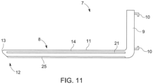
- FIG. 6 shows a fifth embodiment of the load-carrying device 5 or the fork 7, but now in an advantageous side view.
- the fork blade 8 is designed in particular according to one of the above exemplary embodiments.
- the fork tip 13 is advantageously assigned a protective element 25, which protects the fork tip 13 from signs of wear.
- the protective element 25 is arranged on the underside of the fork blade 8 facing away from the top and has a significantly higher abrasion resistance compared to the longitudinal beam 14, depending on the tribology, so that in the event that the fork blade 8 reaches the ground with the free end 12 , in particular while the transport vehicle 1 moves the load-carrying device 5.
- the protective element 25 is optionally formed by one or both of the outer fittings or support elements 15, 16.
- Preferably is it made of stainless steel.
- it is optionally provided that it extends over the entire or almost entire length of the longitudinal beam 14.
- the protective element 25 is also arranged on the underside of the load-carrying device 5 or the fork 7 facing the ground. It extends from the fork tip 13 to the area of the fork bend, so that the fork tine 7 is protected overall against wear caused by contact with the ground.
- the protective element 25 can also be arranged only in the area adjacent to the fork bend. The protective element advantageously extends only over a section of the underside. Arranging the protective element in this area makes sense because this area of the load-carrying device 5 or the fork 7 often comes into contact with the ground when it is picked up or set down and therefore a high level of wear occurs in this area.
- the core element 21 can be made in one piece from a very stable material such as steel or stainless steel and can be surrounded by the longitudinal beam 14 made of plastic. If, in such a configuration, one or more protective elements 25 are arranged on the underside of the load-carrying device 5 facing the ground, these can also be screwed to the load-carrying device 5. A reliable hold is guaranteed by the stability of the core element 21.
- This design makes it possible in a particularly simple manner to remove one or more worn protective elements 25 by loosening the screw connection and to install new protective elements 25. Such a solution requires little effort when replacing the elements and is particularly sustainable because the load-carrying device 5 as such can continue to be used unchanged.
- the fork back 9 has an insertion recess 26 at its lower end, which has an inner contour that at least essentially corresponds to the outer contour of the fork blade 8 at the end 27 facing away from the fork tip 13.
- the fork blade 8 is inserted and inserted into the receiving recess 26 with an insertion section at its end 27 and is thereby positively connected to the fork back 9.
- releasable fastening means 28 are also available, by means of which a user can lock the fork blade 8 on the fork back 9 in the inserted state or release it from it. This makes it possible to easily replace the fork blade 8, for example in the event of signs of wear or damage.
- the transport vehicle 1 has several load-carrying devices available, for example a load-carrying device system, which, however, differ from one another in particular in their length or nature with regard to the support elements 17.
- a load-carrying device system which, however, differ from one another in particular in their length or nature with regard to the support elements 17.
- the load-carrying devices of the load-carrying device system have in common that their ends 27 are designed the same in order to cooperate with the insertion recess 26 as described above.
- the plug connection of the fork blade 8 and the fork back 9 is as in Figure 6 shown, made possible with little additional effort.
- the outer contour of the fork blade 8 at the end 27 and the inner contour of the receiving recess 26 are designed such that the fork blade 8 is held in the receiving recess 26 in a form-fitting manner and in particular without play or almost without play. This ensures precise guidance of the fork blade(s) 8 by means of the transport vehicle 1.
- a sensor 32 in particular, is installed on the fork tip 13 or in the fork back 9 a camera sensor is arranged, which is connected to a control device of the transport vehicle 1 using at least one connection cable guided through one of the through channels 22.
- a display or a screen is arranged in the transport vehicle 1, by means of which the driver or user of the transport vehicle 1 can monitor the camera image captured by the sensor 32 and take it into account for controlling the transport vehicle 1.
- the sixth exemplary embodiment according to Figure 7 differs from the previous exemplary embodiment essentially in that the fork blade 8 and fork back 9 are formed in one piece with one another.
- the longitudinal beam 14 preferably also extends into or through the fork back 9.
- an optional support element 15, 16, 17 extends through the fork carrier 8 into the fork back 9.
- the fork tip 13 is also advantageously assigned a protective element 25, which protects the fork tip 13 from signs of wear.
- the load-carrying device 5 has a support element 29 on the fork back 9, which essentially surrounds the fork back 9 and partially supports the fork blade 8, at least on its underside.
- the carrier element 29 has the aforementioned fastening hooks 10 for mounting the load-carrying device 5 on the fork carriage of the transport vehicle 1.
- the carrier element 29 is preferably designed in several parts, in particular in two parts.
- the carrier element 29 according to the present exemplary embodiment has a first part 29 ', which is arranged on the front of the fork back 9 facing the fork blade 8, and a second part 29", which is arranged on the back of the fork back 9 facing away from the fork blade .
- the part 29" assigned to the back has a curvature at its lower end, which engages under the fork blade 8 in order to support it from below.
- part of the carrier element 29 can also be cast or laminated into the fork back 9 on the inside.
- Figure 8 shows a seventh embodiment of the load-carrying device 5, in which the through channel 22 extends not only through the fork blade 8, but also through the fork back 9. Alternatively, the through channel 22 can also begin in the area of the fork hook 10.
- the fork blade 8 has the above-mentioned fire extinguishing device 40 on the fork tip 13, which is connected to the through-channel 22 and can be supplied with a fire extinguishing medium through the through-channel 22.
- the through channel 22 can be connected at its end facing away from the fire extinguishing device 40, in particular on the free top side of the fork back 9, to a supply hose 31 or the like, which leads, for example, to a media tank which is arranged on or on the body 2 of the transport vehicle 1 .
- the fork blade 8 in each of the described exemplary embodiments has an advantageous anti-slip coating 33 on the top of the longitudinal member 14 or the fork blade 8, which forms the transport surface 11.
- the anti-slip coating 35 ensures that the load picked up on the fork blade 8 cannot slip or can only slip with great difficulty.
- Figure 9 shows a further exemplary embodiment of the load-carrying device 5 in a perspective sectional view.
- the fork blade 8 and fork back are preferably formed in one piece with one another.
- the support elements 17 to 20 are each surrounded with plastic. This is in particular each of the internal support elements is laminated into a plastic layer.
- the through channel 22 is also formed between the middle support elements 18, 19.
- the fork tine is also designed in two parts, as in Figure 9 indicated by dashed dividing lines.
- the fork tine is divided in two in the middle, so that the through channel 22 is formed proportionally by both fork tine parts. This enables simple and cost-effective production of the fork 7.
- the load-carrying device proves to be particularly light and low-wear.
- the fork tine consists of a longitudinal beam made of carbon fiber-reinforced plastic (so-called carbon), which has a core element made of wood, which is completely enclosed by the longitudinal beam.
- a support element made of stainless steel is also arranged on the underside of the longitudinal beam.
- the support element can have a substantially U-shaped cross section, so that the longitudinal sides of the longitudinal beam are covered at least in some areas. A particularly high weight saving is achieved if the support element is only located in the area or adjacent to the fork bend.
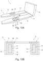
- Figures 10 A and B show an exemplary embodiment of the transport vehicle 1 in training as a pallet truck.
- This essentially differs from the forklift in that it has transport wheels 36 below the respective fork blade 8, which are arranged to be adjustable in height relative to the fork blade 8, in particular in the area of a recess 37 in the fork blade 8, as in the perspective view of Figure 10A shown.
- the respective fork blade 8 has a C- or U-shaped cross section, as in Figure 10B shown, which is a cross-sectional view of the pallet truck along line AA in Figure 10A shows.
- the fork blade 8 has a support element 38 which forms an upper flange which forms the transport surface 11 and has the recess 37.
- Two side legs protrude downwards in one piece from the upper chord, which are arranged at a distance from one another on the long sides of the upper chord and are in particular formed in one piece with it.
- the support element 38 thus encases the underlying longitudinal beam 14 on the top and on the long sides.
- the side legs are designed separately from the upper flange and are formed, for example, by the support elements 15, 16, which are firmly connected to the support elements 38, for example welded, screwed, riveted and / or glued.
- the support elements 15, 16 are made of steel, in particular stainless steel.
- the longitudinal beam also has an opening 39, so that the transport rollers or wheels 36 can lie in the opening.
- the longitudinal beam 14 preferably has two support elements 17, 20 which extend through the longitudinal beam 14 at a distance and at least substantially parallel to one another. The longitudinal beams are so far apart from each other that they extend laterally past the opening 39, so the opening 39 is formed between them, as in Figure 10B shown.
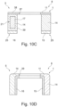
- Figure 10C shows a further exemplary embodiment that differs from the previous exemplary embodiment in that the support elements 15, 16 are not arranged on the side, but at the bottom of the longitudinal beam 14, so that the support elements form underbody protection.
- the support elements 15, 16 in this embodiment correspond to the protective element 25, which extends in particular over the entire length of the longitudinal beam.
- Figure 10C also shows in the drawing plane on the left an exemplary embodiment with a support element 17 as a core element 21 and on the right an exemplary embodiment without a core element 21.
- both sides of the fork blade 8 - in cross section Figure 10C seen - either a core element 21, that is formed from one or more, in particular from a maximum of four, support elements 17 to 20, or no core element 21.
- only one side of the fork blade 8 has a core element 21.
- Figure 10D shows a further exemplary embodiment that differs from the exemplary embodiment of Figure 10B differs in particular in that the support elements 15, 16 are arranged on the inside of the longitudinal beam 14.
- the plastic of the longitudinal beam 14 thus covers the support elements on the top and on the outer side surfaces.
- the longitudinal beam itself also forms the transport surface 11.
- the support elements 15, 16 can also be arranged on the outside of the longitudinal beam 14.
- the respective support element 15 to 20, 38 is preferably welded, cast, laminated, screwed, riveted and/or glued to the respective longitudinal beam 14 in order to ensure a permanently strong connection.
- the longitudinal beam 14 is produced by means of a molding process using a die, male mold or nozzle, in which the plastic is introduced into a mold in which at least one support element is arranged, so that the plastic hardens on the support element and thereby forms a permanently fixed connection with it.
- the load-carrying device according to the invention is a multi-component component, a so-called hybrid component.
- the load-carrying device according to the invention can be manufactured using the cold or hot pressing processes already mentioned. Autoclaves can also be used, which are particularly suitable for pressing fiber composite materials.
- the metallic part is first manufactured and formed in a conventional manner.
- the plastic component is then applied. This can be done by injection molding, laminating, etc.
- the plastic is used as an active medium with which various shaped elements can be inserted into the sheet metal under pressure.
- the hardening of the component can be done, for example, by supplying heat, time and pressure, for example at 80 ° C to 400 ° C in a time of 1 minute to 2,880 minutes.
Description
Die Erfindung betrifft ein Lastaufnahmemittel, insbesondere Gabelzinken für einen Gabelstapler oder Hubwagen, mit zumindest einem längserstreckten Gabelblatt, das eine Transportfläche zur Aufnahme von Transportgut und an einem in Längserstreckung freien ersten Ende eine Gabelspitze aufweist und mehrteilig ausgebildet ist. Weiterhin betrifft die Erfindung ein Transportfahrzeug, insbesondere Gabelstapler oder Hubwagen, mit einer Fahrzeugkarosserie und mit zumindest einem an der Fahrzeugkarosserie insbesondere verlagerbar angeordneten Lastaufnahmemittel, insbesondere Gabelzinken, das wie vorstehend beschrieben ausgebildet ist.The invention relates to a load-carrying device, in particular forks for a forklift or pallet truck, with at least one elongated fork blade, which has a transport surface for receiving transported goods and a fork tip at a first end that is free in the longitudinal extension and is designed in several parts. Furthermore, the invention relates to a transport vehicle, in particular a forklift or pallet truck, with a vehicle body and with at least one load-carrying device, in particular forks, which is arranged in particular displaceably on the vehicle body and which is designed as described above.
Lastaufnahmemittel und Transportfahrzeuge der eingangs genannten Art sind aus dem Stand der Technik bereits bekannt. So beschreibt beispielsweise die Offenlegungsschrift
Die bekannten Lastaufnahmemittel leiden unter ihrem hohen Gewicht, das zusätzlich zu dem Gewicht des Transportguts durch das Transportfahrzeug getragen und bewegt werden muss. Zur Reduzierung des Gewichts ist aus der
Der Erfindung liegt die Aufgabe zugrunde, ein verbessertes Lastaufnahmemittel zu schaffen, durch welches insbesondere das Gewicht des Lastaufnahmemittels reduziert wird, und insbesondere ohne dass dabei die mechanischen Eigenschaften beziehungsweise die Belastbarkeit des Lastaufnahmemittels reduziert werden.The invention is based on the object of creating an improved load-carrying device, through which in particular the weight of the load-carrying device is reduced, and in particular without the mechanical properties or the load-carrying capacity of the load-carrying device being reduced.
Die der Erfindung zugrundeliegende Aufgabe wird durch ein Lastaufnahmemittel mit den Merkmalen des Anspruchs 1 gelöst. Dieses hat den Vorteil, dass durch eine einfache Maßnahme in kostengünstiger und energiesparender Art und Weise das Gewicht des Gabelblatts reduziert wird. Dies kann erfindungsgemäß dadurch erreicht werden, dass das Gabelblatt einen aus Kunststoff gefertigten Längsträger aufweist, der sich zumindest im Wesentlichen entlang des gesamten Gabelblatts in dessen Längserstreckung erstreckt. Hierdurch wird gleichzeitig auch die Korrosionsbeständigkeit des Gabelblatts erhöht. Das Gabelblatt kann somit teilweise aus Kunststoff gefertigt sein, wobei dadurch, dass sich der Kunststoff zumindest im Wesentlichen entlang des gesamten Gabelblatts erstreckt, ein großer Teil des Gabelblatts nunmehr aus Kunststoff fertigbar ist. Dadurch ist das Gewicht des ansonsten häufig aus Metall gefertigten Gabelblatts reduziert. Insbesondere wird erreicht, dass das Gewicht um ca. 25% bis 90%, insbesondere 35% bis 50%, im Vergleich zu herkömmlichen, aus Metall gefertigten Gabelblättern reduziert wird. Um die Robustheit des Gabelblatts auf dem Niveau herkömmlicher Gabelblätter zu halten, weist das Gabelblatt erfindungsgemäß außerdem zumindest ein Stützelement aus einem Material mit einer Verschleißfestigkeit auf, die höher ist als die des Längsträgers beziehungsweise des Kunststoffs. Mit Verschleißfestigkeit im Sinne der vorliegenden Erfindung ist insbesondere die Abriebfestigkeit gemeint. Durch die derartige Ausbildung des Gabelblatts als Verbundbauteil aus einem Längsträger und zumindest einem Stützelement aus unterschiedlichen Materialien wird insbesondere bei gleicher Bauraumbeanspruchung beziehungsweise Größe und Volumen des Gabelblatts im Vergleich zu herkömmlichen Gabelblättern ein reduziertes Gewicht mit nahezu gleicher oder höherer Belastbarkeit geboten. Weiterhin ergibt sich durch die erfindungsgemäße Ausbildung des Lastaufnahmemittels der Vorteil, dass das Lastaufnahmemittel auch in Situationen einsetzbar ist, in welchen herkömmliche Gabelzinken aus Stahl nicht oder nur bedingt einsetzbar sind. Um in Gefahrenzonen Gabelzinken einsetzen zu können, in welchen Funkenflug vermieden werden muss, werden Gabelzinken eingesetzt, die aus Edelstahl gefertigt sind. Diese sind jedoch verhältnismäßig kostenintensiv in der Herstellung und können je nach Tribologie und Reibung dennoch zur Funkenbildung neigen. Durch die erfindungsgemäße Ausbildung wird erreicht, dass Funkenflug kostengünstig vermieden wird. Dabei reicht es aus, dass beispielsweise außen angebrachte Stützelemente in Form von Außenbeschlägen aus Edelstahl gefertigt werden. Weil damit nur ein kleiner Teil des Lastaufnahmemittels aus Edelstahl gefertigt wird, fallen die Herstellungskosten insgesamt niedriger aus. Innen liegende Stützelemente sind durch den Kunststoff eingehüllt und können somit nicht zu Funkenschlag führen. Die vorliegende Erfindung hat außerdem den Vorteil, dass durch den Kunststoff eine insbesondere nur elastische Verformung des Gabelblatts bei hohen Lasten erfolgt, insbesondere wenn als Kunststoff ein faserverstärkter Kunststoff eingesetzt wird. Im Gegensatz dazu ermüden Gabelblätter aus Metall, woraufhin sich diese dauerhaft verbiegen und unbrauchbar werden. In Folge dessen ist mit der Erfindung eine höhere Lebensdauer des Lastaufnahmemittels erzielt. Das Lastaufnahmemittel ist insbesondere fest an einem Transportfahrzeug verbaut oder verbaubar, oder derart ausgebildet, dass es lösbar an einem Transportfahrzeug, insbesondere auswechselbar, befestigbar ist. Besonders bevorzugt weist das Lastaufnahmemittel zwei Gabelblätter auf, die wie obenstehend beschrieben ausgebildet und insbesondere parallel zueinander und beabstandet voneinander angeordnet sind, so dass ihre Transportflächen zumindest im Wesentlichen in einer gemeinsamen Transportflächenebene liegen. Vorzugsweise sind die zwei Gabelblätter an einem gemeinsamen Gabelrücken angeordnet beziehungsweise gehalten.The object on which the invention is based is achieved by a load-carrying device with the features of
Vorzugsweise weist der Kunststoff des Längsträgers eine Dichte im Bereich von 600 kg/m3 bis 3.000 kg/m3 bzw. 0,6 bis 3,0 g/cm3, besonders bevorzugt eine Dichte von 1.400 kg/m3 bis 2.100 kg/m3 bzw. 1,2 bis 2,5 g/cm3. Des Weiteren weist der Kunststoff vorzugsweise eine Bruchdehnung A von 0,2 bis 8,1% und eine Aushärtetemperatur von 20°C bis 700°C auf. Der Längsträger weist bevorzugt eine Zugfestigkeit von 1.500 N/mm2 bis 30.000 N/mm2, vorzugsweise von 2.000 N/mm2 bis 5.000 N/mm2 auf.The plastic of the longitudinal beam preferably has a density in the range of 600 kg/m 3 to 3,000 kg/m 3 or 0.6 to 3.0 g/cm 3 , particularly preferably a density of 1,400 kg/m 3 to 2,100 kg/ m 3 or 1.2 to 2.5 g/cm 3 . Furthermore, the plastic preferably has an elongation at break A of 0.2 to 8.1% and a curing temperature of 20 ° C to 700 ° C. The longitudinal beam preferably has a tensile strength of 1,500 N/mm 2 to 30,000 N/mm 2 , preferably of 2,000 N/mm 2 to 5,000 N/mm 2 .
Besonders bevorzugt weist das zumindest eine Stützelement insbesondere bei einer Anbringung aus Metall außen oder innen an dem Längsträger eine Dichte in einem Bereich von 4.500 kg/m3 bis 8.900 kg/m3, eine Zugfestigkeit von 300 N/mm2 bis 1.450 N/mm2, eine Bruchdehnung A von 10% bis 55 % und eine Schmelztemperatur von 500°C bis 5.500° C auf. Weiterhin ist bevorzugt vorgesehen, dass in dem Fall, dass das Stützelement aus anderen Materialien als Metall gefertigt ist, insbesondere bei einer Anbringung in oder an dem Längsträger, dieses Material eine Dichte von 150 kg/m3 bis 4. 000 kg/m3, eine Zugfestigkeit von 10 N/mm2 bis 30.000 N/mm2 und eine Bruchdehnung A von 0,2 % bis 900% und eine Zersetzungstemperatur oder Aushärtetemperatur von -20°C bis 1.000°C aufweist.Particularly preferably, the at least one support element has a density in a range of 4,500 kg/m 3 to 8,900 kg/m 3 and a tensile strength of 300 N/mm 2 to 1,450 N/mm, particularly when it is made of metal on the outside or inside of the longitudinal beam 2 , an elongation at break A of 10% to 55% and a Melting temperature of 500°C to 5,500°C. Furthermore, it is preferably provided that in the case that the support element is made of materials other than metal, in particular when attached in or on the longitudinal beam, this material has a density of 150 kg/m 3 to 4,000 kg/m 3 , a tensile strength of 10 N/mm 2 to 30,000 N/mm 2 and an elongation at break A of 0.2% to 900% and a decomposition temperature or hardening temperature of -20°C to 1,000°C.
Gemäß einer bevorzugten Weiterbildung der Erfindung ist der Längsträger aus einem faserverstärkten Kunststoff, insbesondere aus glasfaser- oder kohlenstofffaserverstärktem Kunststoff gefertigt. Hierdurch wird die Robustheit beziehungsweise Belastbarkeit des Längsträgers selbst weiter in vorteilhafter Weise erhöht, ohne dass das Gewicht des Gabelblatts eine deutliche Gewichtszunahme erhält. Optional ist der Längsträger aus mehreren Schichten mit faserverstärktem Kunststoff gefertigt, wobei die Faserorientierung benachbarter Schichten bevorzugt unterschiedlich ist, um die Stabilität des Längsträgers weiter zu erhöhen. So ist der Längsträger insbesondere laminiert, extrudiert, gepresst, spritzgepresst, vulkanisiert, geschichtet, beschickt, vakuumgepresst und/oder vakuumgezogen.According to a preferred development of the invention, the longitudinal member is made of a fiber-reinforced plastic, in particular of glass fiber or carbon fiber reinforced plastic. As a result, the robustness or resilience of the longitudinal member itself is further increased in an advantageous manner, without the weight of the fork blade receiving a significant increase in weight. Optionally, the longitudinal beam is made from several layers of fiber-reinforced plastic, with the fiber orientation of adjacent layers preferably being different in order to further increase the stability of the longitudinal beam. The longitudinal beam is in particular laminated, extruded, pressed, injection molded, vulcanized, layered, loaded, vacuum pressed and/or vacuum drawn.
Weiterhin ist bevorzugt vorgesehen, dass sich das zumindest eine Stützelement als Kernelement in Längserstreckung des Gabelblatts erstreckt und von dem Kunststoff umfangsseitig zumindest im Wesentlichen umgeben ist. Insbesondere ist das Kernelement an zumindest einer seiner - bei bestimmungsgemäßem Gebrauch - insbesondere vertikalen Längsseiten und/oder an seiner zumindest im Wesentlichen horizontalen Oberseite von dem Kunststoff bedeckt beziehungsweise umgeben. Das Stützelement ist somit in das Gabelblatt beziehungsweise in den Längsträger integriert angeordnet, sodass es einen Kern des Gabelblatts ausbildet. Dadurch, dass das Stützelement von dem Kunststoff umfangsseitig, also im Querschnitt gesehen, umgeben ist, ist das Stützelement im Inneren des Längsträgers geschützt angeordnet. Auch wird dadurch erreicht, dass das Stützelement nicht mit dem Transportgut selbst in Kontakt kommt, wodurch beispielsweise ein Verschleiß des Stützelements und/oder des Transportguts vorteilhaft durch den Kunststoffmantel des Längsträgers verhindert ist. Darüber hinaus ergibt sich durch das Ummanteln des Kernelements mit dem Kunststoff des Längsträgers der Vorteil, dass eine vorteilhafte mechanische Verbindung von Kunststoff und Kernelement gewährleistet ist.Furthermore, it is preferably provided that the at least one support element extends as a core element in the longitudinal extent of the fork blade and is at least essentially surrounded by the plastic on the circumference. In particular, the core element is covered or surrounded by the plastic on at least one of its - when used as intended - in particular vertical long sides and / or on its at least essentially horizontal top side. The support element is thus arranged integrated into the fork blade or into the longitudinal beam, so that it forms a core of the fork blade. Because the support element is surrounded by the plastic on the circumference, i.e. seen in cross section, the support element is arranged in a protected manner inside the longitudinal beam. This also ensures that the support element does not come into contact with the transported goods themselves, whereby, for example, wear of the support element and/or the transported goods is advantageously prevented by the plastic jacket of the longitudinal beam. Over and beyond The advantage of encasing the core element with the plastic of the longitudinal member is that an advantageous mechanical connection between the plastic and the core element is ensured.
Gemäß einer bevorzugten Ausführungsform der Erfindung ist das Kernelement und/oder das zumindest eine Stützelement aus Holz, Kunststoff, Metall, Sand, Stein, Pappe, Schaum Gewebe, Granulat, Glas, Wolle oder Keramik gefertigt. Während die Ausführung aus Metall eine besonders hohe Verschraubungsfestigkeit für Außen- und/oder Innenbeschläge des Gabelblatts gewährleistet, bietet die Ausführung aus Holz den Vorteil, dass das Kernelement selbst ebenfalls gewichtssparend ausgebildet ist und damit das Gewicht des Gabelblatts weiter reduziert. Das Kernelement, insbesondere der Holzkern, dient als Träger für den Kunststoff des Längsträgers und ist kostengünstig und nachhaltig in der Herstellung, da die Form des Kernelements zumindest im Wesentlichen unabhängig von der Form des Gabelblatts selbst gestaltbar ist. So kann das Kernelement beispielsweise einen quadratischen, kreisförmigen, ovalförmigen, mehreckförmig oder auch dreieckförmig Querschnitt aufweisen, ohne dass dadurch die Form des Gabelblatts, insbesondere im Bereich seiner Transportfläche beeinträchtigt wird. Gemäß einer alternativen Ausführungsform der Erfindung ist das zumindest eine Stützelement ebenfalls aus einem Kunststoff gefertigt, dann jedoch aus einem Kunststoffmaterial, das sich von der Materialeigenschaft des Längsträgers unterscheidet.According to a preferred embodiment of the invention, the core element and/or the at least one support element is made of wood, plastic, metal, sand, stone, cardboard, foam fabric, granules, glass, wool or ceramic. While the metal version ensures a particularly high screw strength for external and/or internal fittings of the fork blade, the wooden version offers the advantage that the core element itself is also weight-saving and thus further reduces the weight of the fork blade. The core element, in particular the wooden core, serves as a support for the plastic of the longitudinal member and is inexpensive and sustainable to produce, since the shape of the core element can be designed at least essentially independently of the shape of the fork blade itself. For example, the core element can have a square, circular, oval, polygonal or even triangular cross-section without thereby affecting the shape of the fork blade, particularly in the area of its transport surface. According to an alternative embodiment of the invention, the at least one support element is also made of a plastic, but then of a plastic material that differs from the material properties of the longitudinal member.
Vorzugsweise weist das Kernelement wenigstens zwei Stützelemente auf, die sich parallel zueinander erstrecken und von dem Kunststoff gemeinsam umgeben sind. Somit bilden zwei Stützelemente das Kernelement des Gabelblatts aus, die durch den Kunststoff eingehaust beziehungsweise zusammengefasst sind. Die Stützelemente werden durch den Kunststoff aneinandergehalten und tragen zur Robustheit und Vergünstigung in der Herstellung des Gabelblatts bei. Durch die Wahl und Anzahl der Stützelemente insbesondere des Kernelements ist eine Anpassung des Gabelblatts an unterschiedliche Randbedingungen, wie beispielsweise an unterschiedliche zu erwartende Gewichtsklassen des Transportguts anpassbar, sodass beispielsweise das Gabelblatt bei gleichbleibenden Au-ßendimensionen durch Wahl des oder der Kernelemente in Bezug auf Anzahl und Material, vorteilhaft an unterschiedliche Lastgüter anpassbar ist. Vorzugsweise liegen die Stützelemente in dem Kunststoff direkt aneinander an, sodass sie bei der Herstellung beispielsweise von dem Kunststoff in einfacher Art und Weise umgossen oder ummantelt werden können. Optional weist das Kernelement mehr als zwei, beispielsweise drei oder vier Stützelemente auf.Preferably, the core element has at least two support elements which extend parallel to one another and are surrounded together by the plastic. Two support elements thus form the core element of the fork blade, which are enclosed or combined by the plastic. The support elements are held together by the plastic and contribute to the robustness and cost-effectiveness of the production of the fork blade. The choice and number of support elements, in particular the core element, allows the fork blade to be adapted to different boundary conditions, such as different expected weight classes of the transported goods adaptable, so that, for example, the fork blade can be advantageously adapted to different loads with constant external dimensions by choosing the core element or elements in terms of number and material. The support elements in the plastic preferably lie directly against one another, so that they can be easily cast or encased by the plastic during production, for example. Optionally, the core element has more than two, for example three or four, support elements.
Vorzugsweise sind wenigstens zwei Stützelemente aus dem gleichen oder aus unterschiedlichen Materialien gefertigt. Durch die Wahl der Materialien der zwei Stützelemente ist die Belastbarkeit des Gabelblatts sowie dessen Gesamtgewicht weiter beeinflussbar. So werden die Materialien vorzugsweise derart gewählt, dass sich aus der Materialkombination vorteilhafte mechanische Eigenschaften für das Kernelement ergeben.Preferably, at least two support elements are made from the same or different materials. By choosing the materials of the two support elements, the load capacity of the fork blade and its total weight can be further influenced. The materials are preferably chosen such that the combination of materials results in advantageous mechanical properties for the core element.
Gemäß einer ersten Weiterbildung der Erfindung sind der Längsträger, das Stützelement und/oder das Kernelement bevorzugt massiv, einteilig oder mehrteilig ausgebildet. Weist das Kernelement mehrere Stützelemente auf, so sind diese bevorzugt jeweils massiv ausgebildet und liegen aneinander an, um einen zumindest im Wesentlichen geschlossenen Querschnitt auszubilden. Dadurch ergibt sich eine besonders hohe Belastbarkeit des Lastaufnahmemittels.According to a first development of the invention, the longitudinal beam, the support element and/or the core element are preferably designed to be solid, in one piece or in several parts. If the core element has a plurality of support elements, these are preferably each solid and lie against one another in order to form an at least essentially closed cross section. This results in a particularly high load-bearing capacity of the load-carrying device.
Gemäß einer zweiten Weiterbildung der Erfindung weisen das Stützelement, das Kernelement und/oder der Längsträger zumindest einen Durchgangskanal zur Führung eines gasförmigen oder flüssigen Mediums und/oder wenigstens eines Verbindungskabels auf. Dazu ist das Kernelement beispielsweise insbesondere in Längserstreckung mit einer Bohrung oder einem Bohrungskanal versehen. Gemäß einer weiteren Ausführungsform der Erfindung, ist das zumindest eine oder zumindest ein Stützelement bevorzugt als Hohlelement ausgebildet, beispielsweise als Rohr, insbesondere aus Stahl oder Holz, mit einem kreisförmigen, rechteckigen oder mehreckigen Querschnitt. Die hohle Ausbildung des Stützelements beziehungsweise das Vorsehen des Durchgangskanals reduziert das Gewicht des Kernelements weiter, sodass auch das Gewicht des Gabelblatts weiter reduziert wird. Optional sind die Stützelemente des Kernelements derart angeordnet und ausgebildet, dass sie zwischen sich zumindest einen Durchgangskanal ausbilden. Dabei sind die Stützelemente selbst vorzugsweise massiv ausgebildet. Die Ausbildung des Durchgangskanals zur Führung eines gasförmigen oder flüssigen Mediums, beispielsweise eines Kühlmediums, Feuerlöschmedium oder dergleichen, oder eines elektrischen Verbindungskabels, das beispielsweise im Bereich der Gabelspitze, des Gabelblatts oder des Gabelrückens mit einer Sensor-, Wiege- oder Kameraeinrichtung verbunden ist, erhöht die Nutzungsmöglichkeiten des vorteilhaften Lastaufnahmemittels. Die erfindungsgemäße Ausbildung des Gabelzinkens ermöglicht eine kostengünstige Integration des Durchgangskanals in das Gabelblatt. Optional wird der Durchgangskanal durch ein Rohrelement, das sich durch das Stützelement oder eines der Stützelemente hindurch erstreckt, aber als separates Bauteil ausgebildet ist, gebildet. So ist beispielsweise in einem aus Holz gefertigten Stützelement, das insbesondere als Kernelement durch den Längsträger verläuft, ein Metallrohr, insbesondere Aluminiumrohr eingesetzt, das den Durchgangkanal ausbildet. Das Rohrelement ist dazu insbesondere in eine Bohrung oder entsprechende Durchgangsöffnung des Stützelements eingeschoben. Besonders bevorzugt führt der Durchgangskanal zu einer insbesondere ansteuerbaren Feuerlöscheinrichtung, die insbesondere an einem von dem Gabelrücken oder Gabelknick abgewandten Ende des Gabelblatts angeordnet ist und beispielsweise eine Spritzdüse aufweist, mittels welcher ein durch den Durchgangskanal gefördertes Feuerlöschmittel ausspritzbar ist.According to a second development of the invention, the support element, the core element and/or the longitudinal beam have at least one through-channel for guiding a gaseous or liquid medium and/or at least one connecting cable. For this purpose, the core element is provided, for example, with a bore or a bore channel, in particular in the longitudinal extent. According to a further embodiment of the invention, the at least one or at least one support element is preferably designed as a hollow element, for example as a tube, in particular made of steel or wood, with a circular, rectangular or polygonal cross section. The hollow design of the support element or the provision of the through channel further reduces the weight of the core element, so that the weight of the fork blade also further reduces is reduced. Optionally, the support elements of the core element are arranged and designed in such a way that they form at least one through-channel between them. The support elements themselves are preferably solid. The design of the through channel for guiding a gaseous or liquid medium, for example a cooling medium, fire extinguishing medium or the like, or an electrical connecting cable, which is connected to a sensor, weighing or camera device, for example in the area of the fork tip, the fork blade or the fork back, increases the possible uses of the advantageous load-carrying device. The inventive design of the fork tine enables cost-effective integration of the through channel into the fork blade. Optionally, the through channel is formed by a tubular element which extends through the support element or one of the support elements but is designed as a separate component. For example, in a support element made of wood, which runs in particular as a core element through the longitudinal beam, a metal tube, in particular an aluminum tube, is inserted, which forms the through-channel. For this purpose, the tubular element is inserted in particular into a bore or corresponding through opening in the support element. Particularly preferably, the through channel leads to a fire extinguishing device that can be controlled in particular, which is arranged in particular at an end of the fork blade facing away from the fork back or fork bend and, for example, has a spray nozzle by means of which a fire extinguishing agent conveyed through the through channel can be sprayed out.
Vorzugsweise ist das jeweilige Stützelement aus einem Holz gefertigt. Es hat sich herausgestellt, dass Holz dem Gabelblatt eine hohe, in vielen Fällen ausreichende Stabilität bietet und kostengünstig in der Herstellung ist.Preferably, the respective support element is made of wood. It has been found that wood offers the fork blade a high level of stability, which in many cases is sufficient, and is inexpensive to produce.
Gemäß einer bevorzugten Ausführungsform weist das Stützelement jeweils einen quadratischen Querschnitt auf. Dadurch ergibt sich zum einen eine kostengünstige Herstellung und zum anderen eine einfache Verwendung in dem Gabelblatt. Insbesondere ergibt sich dadurch auch eine Skalierbarkeit, weil durch das Einsetzen auch mehrerer Versteifungselemente dem Gabelblatt die Belastbarkeit des Gabelblatts mit wenig Aufwand individuell anpassbar ist, indem Stützelemente mit gleichem quadratischem Querschnitt nebeneinander angeordnet werden, wobei die Anzahl und das Material der Stützelemente wählbar ist.According to a preferred embodiment, the support element each has a square cross section. This results, on the one hand, in cost-effective production and, on the other hand, in simple use in the fork blade. In particular, this also results in scalability because the use of several stiffening elements increases the load capacity of the fork blade of the fork blade can be individually adjusted with little effort by arranging support elements with the same square cross-section next to one another, with the number and material of the support elements being selectable.
Besonders bevorzugt weist das Kernelement ein, zwei, drei, vier, fünf oder sechs Stützelemente auf, die in zumindest einer Reihe aneinander anliegen oder benachbart von dem Kunststoff umgeben sind. Dadurch ergibt sich ein vorteilhaftes Paket von Stützelementen, durch welche das Gabelblatt die gewünschte Belastbarkeit erreicht. Die Stützelemente weisen bevorzugt den gleichen Querschnitt auf. Dadurch wird die Teilevielfalt reduziert und die Herstellung vereinfacht. Alternativ weisen zumindest zwei der Stützelemente unterschiedliche Querschnitte auf. Sind mehrere Stützelemente vorhanden, so sind diese bevorzugt aus dem gleichen Material gefertigt. Optional sind zumindest zwei der Stützelemente aus unterschiedlichen Materialien gefertigt.The core element particularly preferably has one, two, three, four, five or six support elements which rest against one another in at least one row or are adjacently surrounded by the plastic. This results in an advantageous package of support elements through which the fork blade achieves the desired load capacity. The support elements preferably have the same cross section. This reduces the variety of parts and simplifies production. Alternatively, at least two of the support elements have different cross sections. If there are several support elements, they are preferably made of the same material. Optionally, at least two of the support elements are made of different materials.
Gemäß einer bevorzugten Weiterbildung der Erfindung ist das zumindest eine Stützelement als Außenbeschlag an dem Längsträger angeordnet. Gemäß dieser Ausführungsform ist das Stützelement somit nicht in den Längsträger integriert, sondern außen an diesem angeordnet. Dadurch wirkt das Stützelement nicht nur als innenliegendes Versteifungsmittel, sondern auch als außenliegendes Schutzelement, das insbesondere den Kunststoff des Längsträgers vor äu-ßeren Einflüssen schützt, wie z.B. das Abtrennen von Fasern in der Lebensmittelindustrie. So ist das Stützelement beispielsweise an den - bei bestimmungsgemäßem Gebrauch - zumindest im Wesentlichen vertikalen oder horizontalen Längsseiten des Längsträgers beziehungsweise des Gabelblatts angeordneten und erstreckt sich entlang der Längsseiten zumindest bis zu der Gabelspitze. Dadurch werden die Längsseiten des Gabelblatts vorteilhaft durch das Stützelement geschützt und abgedichtet. Dabei ist das Stützelement als Außenbeschlag bevorzugt aus Metall gefertigt. Dadurch wird der Verschleiß und Abrieb des Gabelblatts reduziert. Dabei ist das Stützelement insbesondere aus Stahl, vorzugsweise Edelstahl, gefertigt. Gemäß einer weiteren Ausführungsform ist der Außenbeschlag ebenfalls aus Kunststoff oder lebensmittelechten Materialien gefertigt, der sich jedoch von dem Kunststoff des Längsträgers unterscheidet.According to a preferred development of the invention, the at least one support element is arranged as an external fitting on the longitudinal beam. According to this embodiment, the support element is therefore not integrated into the longitudinal beam, but is arranged on the outside of it. As a result, the support element not only acts as an internal stiffener, but also as an external protective element, which in particular protects the plastic of the longitudinal member from external influences, such as the separation of fibers in the food industry. For example, the support element is arranged on the - when used as intended - at least essentially vertical or horizontal longitudinal sides of the longitudinal member or of the fork blade and extends along the longitudinal sides at least to the fork tip. As a result, the long sides of the fork blade are advantageously protected and sealed by the support element. The supporting element is preferably made of metal as an external fitting. This reduces wear and abrasion on the fork blade. The support element is made in particular from steel, preferably stainless steel. According to a further embodiment, the outer fitting is also made of plastic or food-safe materials, which, however, differs from the plastic of the longitudinal beam.
Insbesondere bildet der Außenbeschlag die Transportfläche des Gabelblatts mit oder insgesamt aus. Dadurch wird erreicht, dass der Kunststoff des Längsträgers insbesondere nicht durch das Transportgut direkt beaufschlagt wird. Dadurch wird der Verschleiß des Gabelblatts reduziert. Zum Bilden der Transportfläche ragt insbesondere das einer Längsseite zugeordnete Stützelement beispielsweise bereichsweise über die Oberseite und/oder Unterseite des Längsträgers vor, sodass das Transportgut nicht auf dem Kunststoff direkt aufliegen oder in Kontakt mit dem Kunststoff kommen kann. Alternativ oder zusätzlich ist der Au-ßenbeschlag derart ausgebildet, dass er sich über die Oberseite des Längsträgers hinweg zur Ausbildung der Transportfläche oder eines Transportflächenabschnitts erstreckt. Vorzugsweise ist das jeweilige Stützelement als Außenbeschlag im Querschnitt gesehen U- oder C-förmig ausgebildet, sodass es zwei Seitenschenkel und einen Basisabschnitt aufweist, von welchem die Seitenschenkel insbesondere senkrecht vorstehen. Die Seitenschenkel sind dabei insbesondere derart ausgebildet, dass sie die Seiten des Gabelblatts beziehungsweise des Längsträgers mindestens bereichsweise überdecken, während der Basisabschnitt an der Längsseite des Gabelblatts beziehungsweise des Längsträgers anliegt. Alternativ kann das Stützelement als Außenbeschlag im Querschnitt gesehen I- oder L-förmig ausgebildet sein. Durch jede der genannten Gestaltungen ist eine besonders sichere Arretierung des Stützelements an dem Längsträger gewährleistet. Darüber hinaus bietet dies den Vorteil, dass das Stützelement selbst an der Oberseite des Längsträgers die Transportfläche des Gabelblatts ausbildet oder mitbildet. Ein sehr großer Vorteil ist die Nachhaltigkeit und somit die Umweltfreundlichkeit der erfindungsgemäßen Lösung, da die außenliegenden Stützelemente bei Verschleiß von 10% vom Querschnitt nach Unfallverhütungsvorschrift ISO 5057 auszutauschen sind und dies erfindungsgemäß einzeln und damit einfacher erfolgen kann.In particular, the outer fitting forms the transport surface of the fork blade with or as a whole. This ensures that the plastic of the longitudinal beam is not directly impacted by the transported goods. This reduces wear on the fork blade. To form the transport surface, in particular the support element assigned to a long side projects, for example, in areas over the top and / or bottom of the longitudinal beam, so that the transported goods cannot rest directly on the plastic or come into contact with the plastic. Alternatively or additionally, the outer fitting is designed such that it extends over the top of the longitudinal beam to form the transport surface or a transport surface section. Preferably, the respective support element is designed as an outer fitting U or C-shaped in cross section, so that it has two side legs and a base section, from which the side legs protrude in particular vertically. The side legs are in particular designed in such a way that they cover the sides of the fork blade or the longitudinal beam at least in some areas, while the base section rests on the long side of the fork blade or the longitudinal beam. Alternatively, the support element can be designed as an external fitting I- or L-shaped in cross section. Each of the designs mentioned ensures a particularly secure locking of the support element on the longitudinal beam. In addition, this offers the advantage that the support element itself forms or helps form the transport surface of the fork blade on the top of the longitudinal member. A very big advantage is the sustainability and thus the environmental friendliness of the solution according to the invention, since the external support elements have to be replaced if there is wear of 10% of the cross section in accordance with the accident prevention regulation ISO 5057 and this can be done individually and therefore more easily according to the invention.
Vorzugsweise ist das Gabelblatt mit einem Gabelrücken verbunden, insbesondere einstückig mit dem Gabelrücken ausgebildet. Optional erstreckt sich der Längsträger dabei bis in den Gabelrücken hinein, sodass sich auch für den Gabelrücken die oben genannt Vorteile und Ausbildungsvarianten ergeben.The fork blade is preferably connected to a fork back, in particular formed in one piece with the fork back. Optionally, the longitudinal beam extends into the back of the fork, so that the advantages and design variants mentioned above also arise for the back of the fork.
Gemäß einer bevorzugten Weiterbildung der Erfindung weist das Gabelblatt an seinem von der Gabelspitze abgewandten Ende einen Einsteckabschnitt zum Einstecken in eine Steckaufnahme eines Gabelrückens der Gabelzinke auf. Dadurch ergibt sich ein modularer Zusammenbau von Gabelblatt und Gabelrücken, der zum einen eine einfache Montage und Demontage des Gabelblatts an einem Gabelrücken erlaubt, und zum anderen eine leichte Austauschbarkeit des Gabelblatts bei Verschleißerscheinungen gewährleistet, ohne dass der gesamte Gabelzinken ausgetauscht werden muss. Der Gabelrücken ist insbesondere quer oder senkrecht zu dem Gabelblatt erstreckend ausgebildet oder ausgerichtet und dient insbesondere zur Befestigung der Gabelzinke an einem Transportfahrzeug. Dazu weist der Gabelrücken beispielsweise Haltemittel zur Arretierung der Gabelzinke an einem Transportfahrzeug auf. Bei den Haltemitteln handelt es sich beispielsweise um Haltebolzen, Haken, Vorsprünge und/oder Aufnahmen. Insbesondere weist die Steckaufnahme einen Querschnitt auf, der zumindest im Wesentlichen im Querschnitt des Gabelblatts an dem Einsteckabschnitt entspricht, sodass das Gabelblatt formschlüssig und nahezu spielfrei oder spielfrei in die Steckaufnahme einführbar ist. Optional ist ein Arretiermittel vorhanden, durch welches das Gabelblatt an dem Gabelrücken verliersicher befestigbar, insbesondere lösbar befestigt ist, sodass ein ungewolltes Lösen des Gabelblatts von dem Gabelrücken jederzeit verhindert ist.According to a preferred development of the invention, the fork blade has an insertion section at its end facing away from the fork tip for insertion into a plug-in receptacle of a fork back of the fork tine. This results in a modular assembly of the fork blade and fork back, which on the one hand allows easy assembly and disassembly of the fork blade on a fork back, and on the other hand ensures that the fork blade can be easily replaced in the event of signs of wear without having to replace the entire fork tine. The fork back is designed or aligned in particular to extend transversely or perpendicular to the fork blade and is used in particular to fasten the fork tine to a transport vehicle. For this purpose, the fork back has, for example, holding means for locking the fork tine on a transport vehicle. The holding means are, for example, retaining bolts, hooks, projections and/or receptacles. In particular, the plug-in receptacle has a cross section which corresponds at least substantially to the cross-section of the fork blade on the insertion section, so that the fork blade can be inserted into the plug-in receptacle in a form-fitting manner and with almost no play or play. Optionally, a locking means is available, through which the fork blade can be captively secured to the fork back, in particular releasably fastened, so that unwanted detachment of the fork blade from the fork back is prevented at any time.
Weiterhin ist bevorzugt vorgesehen, dass der Längsträger zumindest eine Vertiefung aufweist, in welcher ein Sensor, insbesondere ein Gewichtssensor, Temperatursensor, Entfernungssensor oder eine Kameraeinrichtung im Gabelblatt oder Gabelrücken angeordnet ist. Mittels des Sensors wird die Funktionalität des Lastaufnahmemittels erhöht. Durch die vorteilhafte Ausbildung des Längsträgers aus Kunststoff ist eine kostengünstige Einbringung von einer oder mehreren Vertiefungen für einen oder mehrere Sensoren erreichbar, insbesondere auch nachträglich. Besonders bevorzugt weist die Vertiefung einen Durchbruch zu dem Durchgangskanal auf, um eine einfache Verkabelung des Sensors zu ermöglichen.Furthermore, it is preferably provided that the longitudinal support has at least one recess in which a sensor, in particular a weight sensor, temperature sensor, distance sensor or a camera device is arranged in the fork blade or fork back. The sensor increases the functionality of the load-carrying device. The advantageous design of the longitudinal beam made of plastic means that one or more recesses for one or more sensors can be introduced cost-effectively, especially subsequently. The recess particularly preferably has an opening to the through-channel in order to enable simple wiring of the sensor.
Gemäß einer bevorzugten Weiterbildung der Erfindung ist das jeweilige Stützelement mit dem jeweiligen Längsträger gegossen, verschraubt, vernietet, verklebt und/oder einlaminiert. Dadurch ist eine dauerhaft sichere Verbindung von Stützelement und Längsträger gewährleistet. Vorzugsweise wird der Kunststoff durch ein Beschickungsverfahren hergestellt oder bearbeitet, und insbesondere in einem Formwerkzeug durch Temperatur und Druck ausgehärtet, in welchem optional auch zumindest ein Stützelement liegt, so dass der Kunststoff vorteilhaft an das Stützelement angeformt wird.According to a preferred development of the invention, the respective support element is cast, screwed, riveted, glued and/or laminated to the respective longitudinal beam. This ensures a permanently secure connection between the support element and the longitudinal beam. Preferably, the plastic is produced or processed by a loading process, and in particular hardened by temperature and pressure in a mold, in which optionally there is also at least one support element, so that the plastic is advantageously molded onto the support element.
Das erfindungsgemäße Transportfahrzeug mit den Merkmalen des Anspruchs 19 zeichnet sich durch die erfindungsgemäße Ausbildung des Lastaufnahmemittels, wie es obenstehend beschrieben wurde, aus. Es ergeben sich hierdurch die bereits genannten Vorteile. Insbesondere ist das Transportfahrzeug ein Flurförderzeug, das motorisiert oder handgeführt ausgebildet ist. So handelt es sich bei dem Transportfahrzeug vorzugsweise um einen Gabelstapler oder um einen handgeführten Hubwagen. Der Gabelstapler weist insbesondere einen Gabelträger auf, an welchem der Gabelzinken befestigbar ist. Alternativ ist der Gabelzinken fest an der Karosserie beispielsweise des Hubwagens verbaut. Ist das Lastaufnahmemittel für den Einsatz an einem Hubwagen ausgebildet, so weist es vorzugsweise wenigstens ein Laufrad, insbesondere eine oder zwei Transportrollen auf, die im Bereich des vorderen Endes des Gabelblatts an dem Gabelblatt drehbar gelagert sind. Die Lagerung weist bevorzugt Mittel zum Anheben und Absenken des Gabelblatts, beziehungsweise zum Verändern der vertikalen Position des Laufrads zu dem Gabelblatt auf.The transport vehicle according to the invention with the features of
Weitere Vorteile und bevorzugte Merkmale und Merkmalskombinationen ergeben sich insbesondere aus dem zuvor Beschriebenen sowie aus den Ansprüchen. Im Folgenden soll die Erfindung anhand der Zeichnung näher erläutert werden. Dazu zeigen
Figur 1- ein Transportfahrzeug mit einem vorteilhaften Lastaufnahmemittel in einer vereinfachten Seitenansicht,
Figur 2- das Lastaufnahmemittel in einer perspektivischen Darstellung gemäß einem ersten Ausführungsbeispiel,
Figur 3- das Lastaufnahmemittel in einer vereinfachten Schnittdarstellung gemäß einem zweiten Ausführungsbeispiel,
Figur 4- das Lastaufnahmemittel in einer vereinfachten Schnittdarstellung gemäß einem dritten Ausführungsbeispiel,
Figur 5- das Lastaufnahmemittel in einer vereinfachten Schnittdarstellung gemäß einem vierten Ausführungsbeispiel,
Figur 6- das Lastaufnahmemittel in einer vereinfachten Seitenansicht gemäß einem fünften Ausführungsbeispiel,
Figur 7- das Lastaufnahmemittel in einer vereinfachten Seitenansicht gemäß einem sechsten Ausführungsbeispiel,
Figur 8- das Lastaufnahmemittel in einer weiteren Seitenansicht gemäß einem siebten Ausführungsbeispiel,
Figur 9- das Lastaufnahmemittel in einer vereinfachten Schnittdarstellung gemäß einem achten Ausführungsbeispiel, und
Figur 10- das Lastaufnahmemittel in beispielhaften Ausbildungen als Hubwagen in vereinfachten Darstellungen;
Figur 11- das Lastaufnahmemittel in einer vereinfachten Seitenansicht gemäß einem weiteren Ausführungsbeispiel.
- Figure 1
- a transport vehicle with an advantageous load-carrying device in a simplified side view,
- Figure 2
- the load-carrying device in a perspective view according to a first exemplary embodiment,
- Figure 3
- the load-carrying device in a simplified sectional view according to a second exemplary embodiment,
- Figure 4
- the load-carrying device in a simplified sectional view according to a third exemplary embodiment,
- Figure 5
- the load-carrying device in a simplified sectional view according to a fourth exemplary embodiment,
- Figure 6
- the load-carrying device in a simplified side view according to a fifth exemplary embodiment,
- Figure 7
- the load-carrying device in a simplified side view according to a sixth exemplary embodiment,
- Figure 8
- the load-carrying device in a further side view according to a seventh exemplary embodiment,
- Figure 9
- the load-carrying device in a simplified sectional view according to an eighth exemplary embodiment, and
- Figure 10
- the load-carrying device in exemplary designs as a pallet truck in simplified representations;
- Figure 11
- the load-carrying device in a simplified side view according to a further exemplary embodiment.
Wie bei einem Gabelstapler 1 üblich, weist die Hebeeinrichtung 4 einen Mast 6 auf, an welchem ein - nicht dargestellter - Gabelträger in der Höhe verschiebbar lagerbar ist. Der Mast und der Gabelträger sind üblicherweise aus Metall, in der Regel aus Stahl hergestellt. Es besteht jedoch auch die Möglichkeit, zur Gewichtsersparnis Mast und Gabelträger aus kohlefaserverstärktem Kunststoff herzustellen. An dem Gabelträger ist das Lastaufnahmemittel 5, vorliegend in Form einer Gabelzinke 7, befestigt, eingehangen oder lösbar befestigbar ist. So ist das Lastaufnahmemittel 5 mittels des Gabelträgers in der Höhe und/oder Breite verstellbar, um ein Transportgut aufzunehmen oder abzulegen. Vorzugsweise weist der Gabelstapler 1 zwei der Lastaufnahmemittel 5 oder ein Lastaufnahmemittel 5 mit zwei Gabelblättern 8, wie sie untenstehend beschrieben sind, auf, die parallel zueinander an dem Gabelträger befestigt sind.As is usual with a
Weiterhin weist das Gabelblatt 8 einen aus Kunststoff gefertigten Längsträger 14 auf, der sich von dem Gabelrücken 9 bis der Gabelspitze 13 und sich damit über die gesamte Länge des Gabelblatts 8 in Längserstreckung erstreckt. Ist der Gabelrücken 9 einstückig mit dem Gabelblatt 8 ausgebildet, wie im Ausführungsbeispiel von
Um die Belastbarkeit des Gabelzinkens 7 weiter zu erhöhen, weist dieser vorliegend zwei Stützelemente 15, 16 auf. Bei den Stützelementen 15, 16 handelt sich um Außenbeschläge des Gabelzinkens 7, die sich jeweils entlang einer Seitenfläche des Gabelzinkens 7 der L-Form des Gabelzinkens 7 folgend ausgebildet sind. Die Außenbeschläge umfassen dabei den Längsträger 14 an dessen Längsseiten C- oder U-förmig, sodass die Außenbeschläge beziehungsweise die Stützelemente 16, 15 selbst die Transportfläche 11 des Gabelblatts 8 ausbilden und ein direkter Kontakt des Transportgut mit dem Kunststoff des Längsträgers 14 verhindert ist.In order to further increase the load capacity of the
Gemäß einer alternativen Ausführungsform der Erfindung sind die Stützelemente im Querschnitt rechteckförmig ausgebildet, wie in Kreis A von
In einer weiteren Ausführungsform der Erfindung sind die Stützelemente 15, 16 allein auf der dem Boden zugewandten Unterseite des Gabelzinkens 7 angeordnet. Zur Vereinfachung des Aufbaus und der Herstellung des Gabelzinkens kann bei dieser Ausführungsform auch nur ein Stützelement zur Anwendung kommen. Vorzugsweise können sich die Stützelemente 15, 16 bzw. das Stützelement auch nur im Bereich des Gabelknicks bzw. unmittelbar benachbart dazu auf der Unterseite des Gabelzinken erstrecken, da dieser Bereich bei der Aufnahme von Lasten sowie dem Absetzen von Lasten dem höchsten Verschleiß unterliegt. Dies hat seine Ursache in der Tatsache, dass der Gabelstapler beim Anheben und Absenken der Gabel oftmals noch in Bewegung ist, sodass der zum Gabelknick benachbarte Bereich über den Boden schleifen kann, was zu erhöhtem Verschleiß in Form von Abrieb führt. Dem ist durch Anbringung der Stützelemente 15, 16 in dem genannten Bereich entgegen gewirkt.In a further embodiment of the invention, the
Die Stützelemente 15, 16 sind aus einem Material gefertigt, das eine im Vergleich zu dem Längsträger 14 höhere Festigkeit und einen geringeren Verschleiß aufweist. Dazu sind die Stützelemente 15, 16 insbesondere aus einem Material mit einer gegenüber dem Kunststoff erhöhten Festigkeit, wie beispielsweise Metall, insbesondere Stahl oder Edelstahl, oder aus einem Keramikwerkstoff gefertigt. Damit ist das Lastaufnahmemittel 5, insbesondere das Gabelblatt 8, mehrteilig in der Art eines Verbundbauteils ausgebildet und vereint geringes Gewicht mit hoher Belastbarkeit. Dadurch wird das zulässige Transportgewicht des Transportfahrzeugs 1 in vorteilhafter Weise durch das reduzierte Eigengewicht des Lastaufnahmemittels 5 erhöht und damit die Effizienz des Transportfahrzeugs 1 verbessert. Alternativ oder zusätzlich weist das Gabelblatt wenigstens ein innenliegendes Stützelement auf, wie mit Bezug auf die weiteren Figuren im Folgenden beschrieben ist, durch welches die Belastbarkeit des Längsträger vorteilhaft erhöht wird und die Herstellkosten sinken.The
Vorzugsweise unterscheiden sich die Materialien der Stützelemente 15, 16 und des Längsträgers 14 in ihrer Dichte, ihrer Bruchdehnung und Temperaturbeständigkeit. Insbesondere weisen die Materialien die folgenden Eigenschaften beziehungsweise Werte auf:
Für die Längsträger, die vorzugsweise aus glasfaser- oder kohleverstärktem Kunststoff, Aramid o. dgl. bestehen, beträgt die Dichte 600 bis 3.000 kg/m3, vorzugsweise 1.400 bis 2.100 kg/m3. Die Zugfestigkeit beträgt 1.500 bis 30.000 N/mm2, vorzugsweise 2.000 bis 5.000 N/mm2. Die Verformungs- bzw. Aushärtetemperatur liegt zwischen 20 und 700°C bei einer Zykluszeit von 1 bis 10.080 Minuten, während die Bruchdehnung A maximal 8,1 % beträgt.Preferably, the materials of the
For the longitudinal beams, which are preferably made of glass fiber or carbon-reinforced plastic, aramid or the like, the density is 600 to 3,000 kg/m 3 , preferably 1,400 to 2,100 kg/m 3 . The tensile strength is 1,500 to 30,000 N/mm 2 , preferably 2,000 to 5,000 N/mm 2 . The deformation or hardening temperature is between 20 and 700°C with a cycle time of 1 to 10,080 minutes, while the elongation at break A is a maximum of 8.1%.
Für die Stützelemente beträgt die Dichte bei Stahl bzw. Metall 4.500 bis 8.900 kg/m3. Die Schmelztemperatur beträgt 500°C bis 5.500°C. Die Zugfestigkeit beträgt 300 bis 1.450 N/mm2. Die Bruchdehnung beträgt-10 bis 50 %. Bei nicht metallischen Stützelementen beträgt die Dichte 20 kg/m3 bis 4.400 kg/m3. Sie haben eine Zugfestigkeit von 10 N/mm2 bis 30.000 N/mm2 und eine Bruchdehnung A zwischen 0,2 % und 900% sowie eine Zersetzungstemperatur von 100°C bis 950°C.For the supporting elements, the density of steel or metal is 4,500 to 8,900 kg/m 3 . The melting temperature is 500°C to 5,500°C. The tensile strength is 300 to 1,450 N/mm 2 . The elongation at break is -10 to 50%. For non-metallic support elements, the density is 20 kg/m 3 to 4,400 kg/m 3 . They have a tensile strength of 10 N/mm 2 to 30,000 N/mm 2 and an elongation at break A between 0.2% and 900% as well as a decomposition temperature of 100°C to 950°C.
Im Folgenden sollen weitere vorteilhafte Ausführungsbeispiele des Lastaufnahmemittels 5 anhand der
Anstelle der außenliegenden Stützelemente 15, 16 aus Metall ist gemäß diesem Ausführungsbeispiel vorgesehen, dass das Gabelblatt 8 ein aus mehreren Stützelementen 17, 18, 19, 20 gebildetes und innenliegendes Kernelement 21 aufweist. Das Kernelement 21 erstreckt sich in Längserstreckung des Gabelblatts 8 innerhalb des Längsträgers 14. Der Längsträger 14 umgibt somit das Kernelement 21 umfangsseitig. Insbesondere ist der Längsträger 14 durch ein Pressverfahren, insbesondere ein Kalt- oder Warmpressverfahren, auf den Längsträger 14 aufgebracht.Instead of the
Die Stützelemente 17, 18, 19, 20 sind vorliegend aus Holz gefertigt und weisen jeweils einen rechteckförmigen Querschnitt auf, wobei die außenliegenden Stützelemente 17, 20 schmaler ausgebildet sind, als die dazwischenliegenden Stützelemente 18, 19, die insbesondere quadratisch sind. Vorzugsweise sind die Schichten der Stützelemente 17 bis 20 unterschiedlich zueinander ausgerichtet. So weisen insbesondere die innenliegenden Stützelemente 18, 19 eine Schichtung auf, die sich von der Schichtung der außenliegenden Stützelemente 17, 20 unterscheidet. Die Stützelemente 17 bis 20 sind dabei vorzugsweise aus einem Holz, insbesondere aus zugfestem Holz gefertigt. Dabei sind die unterschiedlichen Schichten bevorzugt senkrecht zueinander ausgerichtet und verlaufen waagerecht beziehungsweise senkrecht zur Längserstreckung des Gabelblatts 8 oder diagonal dazu. Die Stützelemente 17, 20 des Kernelements 21 liegen in einer Reihe nebeneinander seitlich aneinander an und sind von dem Kunststoff des Längsträgers 14 ummantelt. Insbesondere werden die Stützelemente 17 bis 20 bei der Herstellung von dem Kunststoff des Längsträgers 14 umgossen. Durch den Einsatz von Holz ist der Gabelzinken 7 besonders gewichtssparend ausgebildet und weist dennoch eine ausreichend hohe Belastbarkeit auf. Gemäß einem alternativen Ausführungsbeispiel ist das Kernelement 21 beziehungsweise das jeweilige Stützelement 17 bis 20 aus Keramik, Kunststoff, insbesondere Thermo- oder Duroplasten, Elastomeren, Aramid, Kevlar, Plexiglas, Papier, Pappe, Gewebe, Glas, Beton, Zement, Schaum, Sand, insbesondere Quarzsand, oder Stein gefertigt sein.The
Um die Belastbarkeit weiter zu erhöhen, können optional zusätzlich die in
In Abwandlung des in
Für die Kernelemente beträgt die Dichte 20 bis 9.000 kg/m3. Die Zugfestigkeit beträgt 350 bis 30.000 N/mm2, vorzugsweise 3.000 N/mm2. Die Verformungstemperatur liegt zwischen 70 und 1.890°C, während die Bruchdehnung A maximal 50 % beträgt.For the core elements the density is 20 to 9,000 kg/m 3 . The tensile strength is 350 to 30,000 N/mm 2 , preferably 3,000 N/mm 2 . The deformation temperature is between 70 and 1,890°C, while the elongation at break A is a maximum of 50%.
Vorzugsweise weist das Gabelblatt 8 wenigstens einen Durchgangskanal 22 auf, der sich in Längserstreckung des Gabelblatts 8 von dem Gabelrücken 9 bis zu der Gabelspitze 13 erstreckt, und wie beispielhaft auch in
Der jeweilige Durchgangskanal 22 ist beispielsweise als Kabelführung nutzbar oder ausgebildet, um beispielsweise an der Gabelspitze angeordnete Sensoren, wie beispielsweise Abstandssensoren, Kamerasensoren, Temperatursensoren oder dergleichen, mittels durch das Gabelblatt 8 oder Gabelrücken 9 hindurchgeführter Kabel zu kontaktieren, die beispielsweise mit einer Steuereinrichtung des Transportfahrzeugs 1 verbunden oder verbindbar sind. Zumindest einer der Durchgangskanäle 22 ist bevorzugt als Medienkanal ausgebildet, der also zur Führung eines insbesondere flüssigen oder gasförmigen Mediums ausgebildet ist. So weist die Gabelspitze 13 beispielsweise eine Feuerlöscheinrichtung 40 auf, die durch zumindest einen der Durchgangskanäle 22 mit einem Feuerlöschmedium versorgbar ist, wie beispielsweise in
Optional sind die Stützelemente 17 bis 19 in diesem Ausführungsbeispiel jeweils und/oder durch einen gemeinsamen Flechtschlauch 23 umgeben, der für eine vorteilhafte Verbindung der Stützelemente 17 bis 19 miteinander und/oder zu dem Kunststoff des Längsträgers 14 führt. Insbesondere werden die Stützelemente 17 bis 19 durch den Flechtschlauch 23 aneinandergehalten und anschließend mit dem Kunststoff des Längsträgers 14 umgossen oder ummantelt. Auch in diesem Ausführungsbeispiel sind die Stützelemente 17, 18, 19 bevorzugt aus Holz gefertigt, wobei die benachbarten Stützelemente bevorzugt eine unterschiedliche, insbesondere senkrecht zueinander ausgerichtete Schichtung aufweisen.Optionally, the
Während bei dem vorhergehenden Ausführungsbeispiel außerdem der jeweilige Durchgangskanal 22 geschlossen ausgebildet ist, ist in diesem Ausführungsbeispiel der Durchgangskanal 22 zur Unterseite des Stützelements 18 hin randseitig offen ausgebildet. Dadurch wird der Stützkanal 22 durch das Stützelement 18 einerseits und den Flechtschlauch 23 und/oder den Kunststoff des Längsträgers 14 andererseits begrenzt. Durch die randoffene Ausbildung ergibt sich der Vorteil, dass der Durchgangskanal 22 beispielsweise durch einen kostengünstigen Fräsvorgang in Form einer Nut in die Außenseite des einen Stützelements 18 eingebracht werden kann.While in the previous exemplary embodiment the respective through-
Gemäß einem alternativen Ausführungsbeispiel weist das Gabelblatt 8 ein Kernelement 21 mit nur einem Stützelement 17 auf. Weiterhin ist gemäß einem weiteren Ausführungsbeispiel vorgesehen, dass der Längsträger hohl ausgebildet ist, anstelle des Kernelements 21 also ein Leerraum vorhanden ist, der beispielsweise als Durchgangskanal 22 nutzbar ist oder einfach der Gewichtsreduzierung dient. Insbesondere ist dann vorgesehen, dass der Längsträger wenigstens ein außen liegendes Stützelement 15, 16, insbesondere wenigstens einen Außenbeschlag aufweist.According to an alternative exemplary embodiment, the
Optional ist der Durchgangskanal 22 nicht in einem der Stützelemente 17, 18, sondern allein in dem Träger 14 ausgebildet, wie in
Optional ist der Durchgangskanal 22 in dem Längsträger 14 mittels eines Rohrelements 24 gebildet, das sich durch den Längsträger 14 in Längserstreckung hindurch erstreckt und bei der Fertigung miteingegossen oder beschickt wird. Dadurch ist die Integration des Durchgangskanals 22 in den Längsträger 14 besonders einfach realisierbar.Optionally, the through
Gemäß einem weiteren Ausführungsbeispiel, ebenfalls in
In der Ausführungsform nach
In einer besonders vorteilhaften Ausführungsform der Erfindung kann das Kernelement 21 einteilig aus einem sehr stabilen Werkstoff wie bspw. Stahl oder Edelstahl hergestellt sein und von dem Längsträger 14 aus Kunststoff umgeben sein. Soweit bei einer solchen Ausgestaltung auf der dem Boden zugewandten Unterseite des Lastaufnahmemittels 5 ein oder mehrere Schutzelemente 25 angeordnet sind, können diese auch mit dem Lastaufnahmemittel 5 verschraubt sein. Ein zuverlässiger Halt ist hierbei durch die Stabilität des Kernelements 21 gewährleistet. Durch diese Gestaltung ist es in besonders einfacher Weise möglich, ein oder mehrere verschlissener Schutzelemente 25 durch Lösen der Verschraubung zu entfernen und neue Schutzelemente 25 zu montieren. Eine solche Lösung erfordert wenig Aufwand beim Tausch der Elemente und ist besonders nachhaltig, weil das Lastaufnahmemittel 5 als solches unverändert weiter nutzbar ist.In a particularly advantageous embodiment of the invention, the
Gemäß dem Ausführungsbeispiel von
Dabei weist der Gabelrückens 9 an seinem unteren Ende eine Einsteckaussparung 26 auf, die eine Innenkontur aufweist, die der Außenkontur des Gabelblatts 8 an dem von der Gabelspitze 13 abgewandten Ende 27 zumindest im Wesentlichen entspricht. Das Gabelblatt 8 ist mit einem Einsteckabschnitt an seinem Ende 27 in die Aufnahmeaussparung 26 eingeschoben und eingesteckt und dadurch formschlüssig mit dem Gabelrücken 9 verbunden. Optional sind außerdem lösbare Befestigungsmittel 28 vorhanden, mittels derer ein Benutzer das Gabelblatt 8 an dem Gabelrücken 9 im eingesteckten Zustand arretieren oder von diesem lösen kann. Dadurch ist ein einfacher Austausch des Gabelblatts 8 beispielsweise bei Verschleißerscheinungen oder Beschädigungen möglich. Selbstverständlich können auch in diesem Ausführungsbeispiel ein oder mehrere der Durchgangskanäle 22, wie sie vorstehend beschrieben wurden, in dem Gabelblatt 8 vorhanden sein. Gemäß einem bevorzugten Ausführungsbeispiel stehen dem Transportfahrzeug 1 mehrere Lastaufnahmemittel zu Verfügung, beispielsweise eines Lastaufnahmemittelsystems, die sich jedoch insbesondere in ihrer Länge oder Beschaffenheit bezüglich der Stützelemente 17 voneinander unterscheiden. Dadurch kann das Transportfahrzeug 1 einfach an unterschiedliche Anforderungen angepasst werden, insbesondere an unterschiedliche Transportgüter. Die Lastaufnahmemittel des Lastaufnahmemittelsystems haben gemeinsam, dass ihr Ende 27 gleich ausgebildet sind, um wie oben beschrieben mit der Einsteckaussparung 26 zusammen zu wirken.The fork back 9 has an
Dadurch, dass das Gabelblatt 8 aufgrund des Einsatzes von Kunststoff gewichtssparend ausgebildet ist, wird die Steckverbindung von Gabelblatt 8 und Gabelrücken 9, wie in
In dem Ausführungsbeispiel von
Das sechste Ausführungsbeispiel gemäß
Das Trägerelement 29 ist vorzugsweise mehrteilig ausgebildet, insbesondere zweiteilig. So weist das Trägerelement 29 gemäß dem vorliegenden Ausführungsbeispiel ein erstes Teil 29' auf, das an der dem Gabelblatt 8 zugewandten Vorderseite des Gabelrückens 9 angeordnet ist, und ein zweites Teil 29", das an der von dem Gabelblatt abgewandten Rückseite des Gabelrückens 9 angeordnet ist. Die beiden Teile 29', 29" sind vorzugsweise mittels mehrerer Befestigungsschrauben 30 miteinander verschraubt, die sich durch den Gabelrücken 9 hindurch erstrecken und in
In Abwandlung des Ausführungsbeispiels kann auch ein Teil des Trägerelements 29 innenliegend in den Gabelrücken 9 eingegossen bzw. einlaminiert sein.In a modification of the exemplary embodiment, part of the
Besonders bevorzugt weist das Gabelblatt 8 in jedem der beschriebenen Ausführungsbeispiele eine vorteilhafte Antirutschbeschichtung 33 auf der Oberseite des Längsträgers 14 beziehungsweise des Gabelblatts 8 auf, welche die Transportfläche 11 ausbildet. Durch die Antirutschbeschichtung 35 wird erreicht, dass aufgenommenes Ladegut auf dem Gabelblatt 8 nicht oder nur sehr schwer verrutschen kann.Particularly preferably, the
Während die vorliegenden Ausführungsbeispiele mit Bezug auf einen Gabelstapler beschrieben sind, sind die unterschiedlich ausgebildeten Gabelzinken 7 beziehungsweise Lastaufnahmemittel 5 natürlich auch bei einem anderen Transportfahrzeug, insbesondere bei einem Hubwagen, einsetzbar.While the present exemplary embodiments are described with reference to a forklift, the differently designed
Optional ist der Gabelzinken außerdem zweiteilig ausgebildet, wie in
Insgesamt erweist sich das Lastaufnahmemittel nach der Erfindung als besonders leicht und verschleißarm. Hierzu hat es sich als besonders vorteilhaft herausgestellt, wenn der Gabelzinken aus einem Längsträger aus kohlefaserverstärktem Kunststoff (sog. Carbon) besteht, der ein Kernelement aus Holz aufweist, welches vom Längsträger vollständig umschlossen ist. Weiter ist an der Unterseite des Längsträgers ein Stützelement aus Edelstahl angeordnet. Das Stützelement kann dabei einen im Wesentlichen U-förmigen Querschnitt haben, sodass die Längsseiten des Längsträgers mindestens bereichsweise umfasst sind. Eine besonders hohe Gewichtsersparnis ist hervorgerufen, wenn das Stützelement sich lediglich im Bereich bzw. benachbart zum Gabelknick befindet.Overall, the load-carrying device according to the invention proves to be particularly light and low-wear. For this purpose, it has proven to be particularly advantageous if the fork tine consists of a longitudinal beam made of carbon fiber-reinforced plastic (so-called carbon), which has a core element made of wood, which is completely enclosed by the longitudinal beam. A support element made of stainless steel is also arranged on the underside of the longitudinal beam. The support element can have a substantially U-shaped cross section, so that the longitudinal sides of the longitudinal beam are covered at least in some areas. A particularly high weight saving is achieved if the support element is only located in the area or adjacent to the fork bend.
Dabei weist das Gabelblatt 8 ein Stützelement 38 auf, das einen Obergurt ausbildet, der die Transportfläche 11 bildet und die Aussparung 37 aufweist. Von dem Obergurt stehen einstückig zwei Seitenschenkel nach unten vor, die beabstandet zueinander an den Längsseiten des Obergurts angeordnet und insbesondere einstückig mit diesem ausgebildet sind. Das Stützelement 38 ummantelt somit den darunter liegenden Längsträger 14 an der Oberseite und an den Längsseiten.The
Gemäß einem alternativen Ausführungsbeispiel, in
Unabhängig von dem jeweiligen Ausführungsbeispiel ist das jeweilige Stützelement 15 bis 20, 38 mit dem jeweiligen Längsträger 14 vorzugsweise verschweißt, eingegossen, einlaminiert, verschraubt, vernietet und/oder verklebt, um eine dauerhaft feste Verbindung zu gewährleisten. Insbesondere ist der Längsträger 14 mittels Formungsverfahren anhand Matrize, Patrize oder Düse hergestellt, bei welchem der Kunststoff in ein Formwerkzeug eingebracht wird, in welchem zumindest ein Stützelement angeordnet ist, sodass der Kunststoff an dem Stützelement aushärtet und dadurch eine dauerhaft feste Verbindung mit diesem eingeht.Regardless of the respective exemplary embodiment, the
Bei dem erfindungsgemäßen Lastaufnahmemittel handelt es sich um ein MehrKomponenten-Bauteil, ein sog. Hybrid-Bauteil. Die Herstellung des erfindungsgemäßen Lastaufnahmemittels kann mit den bereits genannten Kalt- oder Warmpressverfahren erfolgen. Es können darüber hinaus auch Autoklaven zur Anwendung kommen, die insbesondere zum Verpressen von Faserverbundwerkstoffen geeignet sind. In jedem Fall wird das metallische Teil zunächst auf herkömmliche Weise hergestellt und geformt. Im Anschluss erfolgt das Aufbringen der Kunststoff-Komponente. Dies kann durch Spritzgießen, Laminieren usw. erfolgen. Der Kunststoff wird dabei als Wirkmedium benutzt, mit dem sich unter Druck zusätzlich verschiedene Formelemente in das Blech einbringen lassen. Das Aushärten des Bauteils kann bspw. durch Zuführen von Wärme, Zeit und Druck, bspw. bei 80°C bis 400°C in einer Zeit von 1 Minute bis 2.880 Minuten erfolgen.The load-carrying device according to the invention is a multi-component component, a so-called hybrid component. The load-carrying device according to the invention can be manufactured using the cold or hot pressing processes already mentioned. Autoclaves can also be used, which are particularly suitable for pressing fiber composite materials. In any case, the metallic part is first manufactured and formed in a conventional manner. The plastic component is then applied. This can be done by injection molding, laminating, etc. The plastic is used as an active medium with which various shaped elements can be inserted into the sheet metal under pressure. The hardening of the component can be done, for example, by supplying heat, time and pressure, for example at 80 ° C to 400 ° C in a time of 1 minute to 2,880 minutes.
Claims (27)
- Load-receiving means (5), in particular fork prongs (7) for a forklift or lift truck, having at least one longitudinally extending fork blade (8), which has a transport surface (11) for receiving transport goods and a fork tip (13) on a first end (12) which is free in longitudinal extension, wherein the fork blade (8) has a longitudinal member (14) made of plastic, which extends at least substantially along the entire fork blade (8) in longitudinal extension, characterised in that the fork blade (8) is constructed in several parts and in that the fork blade (8) has at least one support element (15 to 19) made of a material with a wear resistance which is higher than that of the longitudinal member (14).
- Load-receiving means according to claim 1, characterised in that the longitudinal member (14) is made of fibre reinforced plastic, in particular of glass-fibre or carbon-fibre reinforced plastic.
- Load-receiving means according to one of the previous claims, characterised in that the at least one support element (17 to 20) extends as a core element (21) in the longitudinal extension of the fork blade (8) and is at least substantially circumferentially surrounded by the plastic.
- Load-receiving means according to one of the previous claims, characterised in that the core element (21) and/or the support element (15 to 20) is made of wood, metal or a ceramic material.
- Load-receiving means according to one of the previous claims, characterised in that the at least two support elements (15 to 20) are made of the same or different materials.
- Load-receiving means according to one of the previous claims, characterised in that the core element (21) and/or the longitudinal member (14) has at least one through-channel (22) for guiding a gaseous or liquid medium and/or at least one electric connecting cable.
- Load-receiving means according to one of the previous claims, characterised in that the respective support element (15 to 20) is made of wood and in that at least two adjacent support elements (15 to 20) are aligned differently, preferably perpendicularly with respect to one another.
- Load-receiving means according to one of the previous claims, characterised in that the respective support element (17 to 20) of the core element (21) has an angular, in particular triangular, rectangular, polygonal, square, round or oval cross-section.
- Load-receiving means according to one of the previous claims, characterised in that the core element (21) has exactly one, two, three, four, five or six support elements (17 to 20), which rest laterally against one another in a row and are jointly surrounded by the plastic of the longitudinal member (14).
- Load-receiving means according to one of the previous claims, characterised in that the at least one support element (15, 16) is arranged as an external fitting on the longitudinal member (14).
- Load-receiving means according to one of the previous claims, characterised in that the external fitting is part of or forms the transport surface (11).
- Load-receiving means according to one of the previous claims, characterised in that the fork blade (8), at its end (27) facing away from the fork tip (13), has an insertion section for inserting into an insertion receptacle (26) of a fork back (9) of the fork prong (7).
- Load-receiving means according to one of the previous claims, characterised in that the longitudinal member (14) has at least one recess (34), in which a sensor (35), in particular a weight sensor, temperature sensor and/or distance sensor is arranged.
- Load-receiving means according to one of the previous claims, characterised in that the support element (17 to 20), the core element (21) and/or the longitudinal member (14) have at least one through-channel (22) for guiding a gaseous or liquid medium and/or at least one electric connecting cable.
- Load-receiving means according to claim 16, characterised in that the through-channel leads to a fire extinguishing device (40), in particular a controllable one, which is arranged in particular at an end (12) of the fork blade (8) facing away from the fork back (9).
- Load-receiving means according to one of the previous claims, characterised in that the plastic of the longitudinal member (14) has a density of 600 kg/m3 to 3,000 kg/m3 or 0.6 to 3.0 g/cm3, particularly preferably a density of 1,200 kg/m3 to 2,500 kg/m3 or 1.2 to 2.5 g/cm3, the support element (15, 16) when mounted on the outside of the longitudinal member (14) has a density of 4,500 kg/m3 to 9,100 kg/m3 and/or the support element (15, 16) made of wood when arranged in the longitudinal member has a density of 20 kg/m3 to 4,400 kg/m3.
- Load-receiving means according to one of the previous claims, characterised in that the respective support element (15 to 20, 38) is welded, cast, laminated, screwed, riveted and/or bonded to the respective longitudinal member (14).
- Load-receiving means according to one of the previous claims, characterised in that the support elements (15, 16) are arranged solely on the underside of the fork prong (7) facing the ground.
- Load-receiving means according to one of the previous claims, characterised in that only one support element (15, 16) is arranged on the underside of the fork prong (7) facing the ground.
- Load-receiving means according to claim 20 or 21, characterised in that the at least one support element extends in the area of the fork bend or immediately adjacent to the fork bend on the underside of the fork prong (7).
- Load-receiving means according to one of claims 18 to 20, characterised in that at least one support element (15, 16) forms a protective element (25).
- Load-receiving means according to claim 21, characterised in that the at least one protective element (25) is screwed, cast or bonded to the core element (21).
- Load-receiving means according to one of the previous claims, characterised in that the material of the support element (15 to 20) and/or the core element (21) is free of metal and has a density of 50 kg/m3 to 4,000 kg/m3, a tensile strength of 10 N/mm2 to 30,000 N/mm2 and an elongation at break A of 0.2 % to 900 % and a decomposition temperature or curing temperature of -20°C to 1,000°C.
- Load-receiving means according to one of the previous claims, characterised in that the longitudinal member (14) has a tensile strength of at least 1,500 N/mm2 and an elongation at break A of 0.2 to 10%.
- Load-receiving means according to one of the previous claims, characterised in that the longitudinal member (14) has a density of 200 kg/m3 to 4,000 kg/m3 and is formed and cured by means of a compression moulding tool or a template or film in a press and/or an autoclave and/or an annealing furnace and/or a vacuum pump or in an extruder at a temperature of 20°C to 900°C in the time 10 seconds to 30,240 minutes.
- Load-receiving means according to one of the previous claims, characterised in that the longitudinal member (14) has an integrated sensor/camera in the fork back (9) or a fire extinguishing unit (40) in the fork blade (8).
- Transport vehicle (1), in particular forklift or lift truck, with a vehicle body (2) and at least one load-receiving means particularly displaceably arranged on the vehicle body (2), in particular fork prongs (7), characterised by the design of the load-receiving means (5) according to one or more of claims 1 to 26.
Applications Claiming Priority (2)
| Application Number | Priority Date | Filing Date | Title |
|---|---|---|---|
| DE102021209678 | 2021-09-02 | ||
| PCT/EP2022/074458 WO2023031404A1 (en) | 2021-09-02 | 2022-09-02 | Load-receiving means, in particular fork prongs |
Publications (3)
| Publication Number | Publication Date |
|---|---|
| EP4172099A1 EP4172099A1 (en) | 2023-05-03 |
| EP4172099B1 true EP4172099B1 (en) | 2024-02-28 |
| EP4172099C0 EP4172099C0 (en) | 2024-02-28 |
Family
ID=83361007
Family Applications (1)
| Application Number | Title | Priority Date | Filing Date |
|---|---|---|---|
| EP22772936.5A Active EP4172099B1 (en) | 2021-09-02 | 2022-09-02 | Load-receiving means, in particular fork prongs |
Country Status (3)
| Country | Link |
|---|---|
| EP (1) | EP4172099B1 (en) |
| CN (1) | CN117222594A (en) |
| WO (1) | WO2023031404A1 (en) |
Family Cites Families (4)
| Publication number | Priority date | Publication date | Assignee | Title |
|---|---|---|---|---|
| DE19515834C1 (en) | 1995-04-29 | 1996-05-23 | Vetter Umformtechnik Gmbh | Fork tine for forklift truck |
| US20070170002A1 (en) * | 2006-01-26 | 2007-07-26 | Richard Ziebell | Fork lift attachment, and methods |
| CN211998678U (en) * | 2020-03-16 | 2020-11-24 | 郑州铁路职业技术学院 | Firm diversified novel transport fork truck |
| CN113060490B (en) * | 2021-03-31 | 2022-08-16 | 昆山精讯电子技术有限公司 | Liquid crystal display panel carrying trolley |
-
2022
- 2022-09-02 EP EP22772936.5A patent/EP4172099B1/en active Active
- 2022-09-02 WO PCT/EP2022/074458 patent/WO2023031404A1/en unknown
- 2022-09-02 CN CN202280031905.8A patent/CN117222594A/en active Pending
Also Published As
| Publication number | Publication date |
|---|---|
| EP4172099A1 (en) | 2023-05-03 |
| WO2023031404A1 (en) | 2023-03-09 |
| CN117222594A (en) | 2023-12-12 |
| EP4172099C0 (en) | 2024-02-28 |
Similar Documents
| Publication | Publication Date | Title |
|---|---|---|
| AT520371B1 (en) | Device for use in handling a load and method for producing such a device | |
| EP2648965B1 (en) | Motor vehicle body with stiffening struts | |
| EP2360082B1 (en) | Longitudinal member for a chassis and method for producing same | |
| EP2593394B1 (en) | Add-on device to be attached to a lifting vehicle, and method for operating said add-on device | |
| DE102007046868A1 (en) | Transport device for carriers and method for their control | |
| DE3113791A1 (en) | "TUBULAR HOLLOW BODY, PROCESS FOR ITS PRODUCTION AND DEVICE FOR IMPLEMENTING THE PROCESS" | |
| EP2527231A2 (en) | Axle craddle for motor vehicles made of a fiber reinforced plastic | |
| DE102005009361A1 (en) | Truck | |
| AT503547B1 (en) | Mold for fiber-reinforced, plastic-composite aerospace components, comprises supported, fiber-reinforced composite with low coefficient of thermal expansion | |
| WO2008125076A1 (en) | Leaf spring made of a fiber-plastic composite and force transmission element therefor | |
| EP1698583B1 (en) | Adaptable sliding bearing for a telescopic crane | |
| EP4172099B1 (en) | Load-receiving means, in particular fork prongs | |
| EP3517483A1 (en) | Reach truck with a counterweight | |
| DE10312432A1 (en) | Industrial truck with a frame | |
| EP3144265B2 (en) | Lifting device with a chassis frame | |
| DE102015008053A1 (en) | Fan with at least one fan and / or other fan parts and method for producing a fan part of a fan | |
| DE202005015354U1 (en) | Industrial truck for transporting e.g. load, has upper load sledge that is above lower load sledge, and leads from hub mast, where impellers are provided for sledges and fork prongs are attached at lower load sledge | |
| DE102016007327A1 (en) | Device for storing and / or transporting components | |
| DE102011052068A1 (en) | Conveyer system for transporting vehicle chassis in automobile production line, has carrying unit that is provided for carrying vehicle chassis and provided with composite material | |
| DE102014008720A1 (en) | Heavy truck with forklift function | |
| DE202007012787U1 (en) | Injection molding machine with two-part construction | |
| EP2366654B1 (en) | Steering a straddle carrier | |
| EP2998159B1 (en) | Tank carriage trailer for liquids | |
| DE102021118286B4 (en) | Underbody protection element made of duroplastic material, manufacturing method and motor vehicle with an underbody protection element | |
| DE102016121550B3 (en) | Fiber composite component and its production |
Legal Events
| Date | Code | Title | Description |
|---|---|---|---|
| STAA | Information on the status of an ep patent application or granted ep patent |
Free format text: STATUS: UNKNOWN |
|
| STAA | Information on the status of an ep patent application or granted ep patent |
Free format text: STATUS: THE INTERNATIONAL PUBLICATION HAS BEEN MADE |
|
| PUAI | Public reference made under article 153(3) epc to a published international application that has entered the european phase |
Free format text: ORIGINAL CODE: 0009012 |
|
| STAA | Information on the status of an ep patent application or granted ep patent |
Free format text: STATUS: REQUEST FOR EXAMINATION WAS MADE |
|
| 17P | Request for examination filed |
Effective date: 20230130 |
|
| AK | Designated contracting states |
Kind code of ref document: A1 Designated state(s): AL AT BE BG CH CY CZ DE DK EE ES FI FR GB GR HR HU IE IS IT LI LT LU LV MC MK MT NL NO PL PT RO RS SE SI SK SM TR |
|
| GRAP | Despatch of communication of intention to grant a patent |
Free format text: ORIGINAL CODE: EPIDOSNIGR1 |
|
| STAA | Information on the status of an ep patent application or granted ep patent |
Free format text: STATUS: GRANT OF PATENT IS INTENDED |
|
| INTG | Intention to grant announced |
Effective date: 20231103 |
|
| GRAS | Grant fee paid |
Free format text: ORIGINAL CODE: EPIDOSNIGR3 |
|
| GRAA | (expected) grant |
Free format text: ORIGINAL CODE: 0009210 |
|
| STAA | Information on the status of an ep patent application or granted ep patent |
Free format text: STATUS: THE PATENT HAS BEEN GRANTED |
|
| AK | Designated contracting states |
Kind code of ref document: B1 Designated state(s): AL AT BE BG CH CY CZ DE DK EE ES FI FR GB GR HR HU IE IS IT LI LT LU LV MC MK MT NL NO PL PT RO RS SE SI SK SM TR |
|
| DAV | Request for validation of the european patent (deleted) | ||
| DAX | Request for extension of the european patent (deleted) | ||
| REG | Reference to a national code |
Ref country code: GB Ref legal event code: FG4D Free format text: NOT ENGLISH |
|
| REG | Reference to a national code |
Ref country code: CH Ref legal event code: EP |
|
| REG | Reference to a national code |
Ref country code: DE Ref legal event code: R096 Ref document number: 502022000568 Country of ref document: DE |
|
| REG | Reference to a national code |
Ref country code: IE Ref legal event code: FG4D Free format text: LANGUAGE OF EP DOCUMENT: GERMAN |
|
| U01 | Request for unitary effect filed |
Effective date: 20240313 |