EP4170749A1 - Verbund-lithiummetall-negativelektrode, herstellungsverfahren dafür und lithiumsekundärbatterie und vorrichtung - Google Patents
Verbund-lithiummetall-negativelektrode, herstellungsverfahren dafür und lithiumsekundärbatterie und vorrichtung Download PDFInfo
- Publication number
- EP4170749A1 EP4170749A1 EP20943700.3A EP20943700A EP4170749A1 EP 4170749 A1 EP4170749 A1 EP 4170749A1 EP 20943700 A EP20943700 A EP 20943700A EP 4170749 A1 EP4170749 A1 EP 4170749A1
- Authority
- EP
- European Patent Office
- Prior art keywords
- lithium
- buffer layer
- porous framework
- negative electrode
- lithium metal
- Prior art date
- Legal status (The legal status is an assumption and is not a legal conclusion. Google has not performed a legal analysis and makes no representation as to the accuracy of the status listed.)
- Pending
Links
Images


Classifications
-
- H—ELECTRICITY
- H01—ELECTRIC ELEMENTS
- H01M—PROCESSES OR MEANS, e.g. BATTERIES, FOR THE DIRECT CONVERSION OF CHEMICAL ENERGY INTO ELECTRICAL ENERGY
- H01M4/00—Electrodes
- H01M4/02—Electrodes composed of, or comprising, active material
- H01M4/13—Electrodes for accumulators with non-aqueous electrolyte, e.g. for lithium-accumulators; Processes of manufacture thereof
- H01M4/134—Electrodes based on metals, Si or alloys
-
- H—ELECTRICITY
- H01—ELECTRIC ELEMENTS
- H01M—PROCESSES OR MEANS, e.g. BATTERIES, FOR THE DIRECT CONVERSION OF CHEMICAL ENERGY INTO ELECTRICAL ENERGY
- H01M4/00—Electrodes
- H01M4/02—Electrodes composed of, or comprising, active material
- H01M4/36—Selection of substances as active materials, active masses, active liquids
- H01M4/38—Selection of substances as active materials, active masses, active liquids of elements or alloys
- H01M4/381—Alkaline or alkaline earth metals elements
- H01M4/382—Lithium
-
- H—ELECTRICITY
- H01—ELECTRIC ELEMENTS
- H01M—PROCESSES OR MEANS, e.g. BATTERIES, FOR THE DIRECT CONVERSION OF CHEMICAL ENERGY INTO ELECTRICAL ENERGY
- H01M10/00—Secondary cells; Manufacture thereof
- H01M10/05—Accumulators with non-aqueous electrolyte
- H01M10/052—Li-accumulators
-
- H—ELECTRICITY
- H01—ELECTRIC ELEMENTS
- H01M—PROCESSES OR MEANS, e.g. BATTERIES, FOR THE DIRECT CONVERSION OF CHEMICAL ENERGY INTO ELECTRICAL ENERGY
- H01M10/00—Secondary cells; Manufacture thereof
- H01M10/05—Accumulators with non-aqueous electrolyte
- H01M10/052—Li-accumulators
- H01M10/0525—Rocking-chair batteries, i.e. batteries with lithium insertion or intercalation in both electrodes; Lithium-ion batteries
-
- H—ELECTRICITY
- H01—ELECTRIC ELEMENTS
- H01M—PROCESSES OR MEANS, e.g. BATTERIES, FOR THE DIRECT CONVERSION OF CHEMICAL ENERGY INTO ELECTRICAL ENERGY
- H01M4/00—Electrodes
- H01M4/02—Electrodes composed of, or comprising, active material
- H01M4/04—Processes of manufacture in general
- H01M4/0402—Methods of deposition of the material
- H01M4/0416—Methods of deposition of the material involving impregnation with a solution, dispersion, paste or dry powder
-
- H—ELECTRICITY
- H01—ELECTRIC ELEMENTS
- H01M—PROCESSES OR MEANS, e.g. BATTERIES, FOR THE DIRECT CONVERSION OF CHEMICAL ENERGY INTO ELECTRICAL ENERGY
- H01M4/00—Electrodes
- H01M4/02—Electrodes composed of, or comprising, active material
- H01M4/04—Processes of manufacture in general
- H01M4/0471—Processes of manufacture in general involving thermal treatment, e.g. firing, sintering, backing particulate active material, thermal decomposition, pyrolysis
-
- H—ELECTRICITY
- H01—ELECTRIC ELEMENTS
- H01M—PROCESSES OR MEANS, e.g. BATTERIES, FOR THE DIRECT CONVERSION OF CHEMICAL ENERGY INTO ELECTRICAL ENERGY
- H01M4/00—Electrodes
- H01M4/02—Electrodes composed of, or comprising, active material
- H01M4/13—Electrodes for accumulators with non-aqueous electrolyte, e.g. for lithium-accumulators; Processes of manufacture thereof
- H01M4/139—Processes of manufacture
- H01M4/1395—Processes of manufacture of electrodes based on metals, Si or alloys
-
- H—ELECTRICITY
- H01—ELECTRIC ELEMENTS
- H01M—PROCESSES OR MEANS, e.g. BATTERIES, FOR THE DIRECT CONVERSION OF CHEMICAL ENERGY INTO ELECTRICAL ENERGY
- H01M4/00—Electrodes
- H01M4/02—Electrodes composed of, or comprising, active material
- H01M4/64—Carriers or collectors
- H01M4/70—Carriers or collectors characterised by shape or form
- H01M4/80—Porous plates, e.g. sintered carriers
- H01M4/808—Foamed, spongy materials
-
- H—ELECTRICITY
- H01—ELECTRIC ELEMENTS
- H01M—PROCESSES OR MEANS, e.g. BATTERIES, FOR THE DIRECT CONVERSION OF CHEMICAL ENERGY INTO ELECTRICAL ENERGY
- H01M4/00—Electrodes
- H01M4/02—Electrodes composed of, or comprising, active material
- H01M2004/021—Physical characteristics, e.g. porosity, surface area
-
- H—ELECTRICITY
- H01—ELECTRIC ELEMENTS
- H01M—PROCESSES OR MEANS, e.g. BATTERIES, FOR THE DIRECT CONVERSION OF CHEMICAL ENERGY INTO ELECTRICAL ENERGY
- H01M4/00—Electrodes
- H01M4/02—Electrodes composed of, or comprising, active material
- H01M2004/026—Electrodes composed of, or comprising, active material characterised by the polarity
- H01M2004/027—Negative electrodes
-
- Y—GENERAL TAGGING OF NEW TECHNOLOGICAL DEVELOPMENTS; GENERAL TAGGING OF CROSS-SECTIONAL TECHNOLOGIES SPANNING OVER SEVERAL SECTIONS OF THE IPC; TECHNICAL SUBJECTS COVERED BY FORMER USPC CROSS-REFERENCE ART COLLECTIONS [XRACs] AND DIGESTS
- Y02—TECHNOLOGIES OR APPLICATIONS FOR MITIGATION OR ADAPTATION AGAINST CLIMATE CHANGE
- Y02E—REDUCTION OF GREENHOUSE GAS [GHG] EMISSIONS, RELATED TO ENERGY GENERATION, TRANSMISSION OR DISTRIBUTION
- Y02E60/00—Enabling technologies; Technologies with a potential or indirect contribution to GHG emissions mitigation
- Y02E60/10—Energy storage using batteries
Definitions
- This application relates to the field of batteries, and specifically, to a composite lithium metal negative electrode, a preparation method thereof, a lithium secondary battery, and an apparatus.
- Lithium metal has been deemed as the "holy grail" of negative electrode materials for next-generation high-energy-density secondary batteries due to its advantages such as high theoretical specific capacity, low reduction potential, minimum atomic radius, and low density.
- lithium dendrites are a prominent technical problem.
- lithium dendrites are inevitably generated.
- Growth of lithium dendrites not only causes irreversible loss of lithium elements, resulting in reduced cycling performance of a battery, but also may pierce a separator, leading to short-circuiting of the battery or even a fire, posing great potential risks to use of lithium metal secondary batteries. Therefore, suppressing the growth of lithium dendrites has become an urgent problem to be resolved.
- this application provides a composite lithium metal negative electrode, a preparation method thereof, a lithium secondary battery, and an apparatus.
- this application provides a composite lithium metal negative electrode, including lithium metal and a lithium buffer layer on at least one surface of the lithium metal, where the lithium buffer layer includes a porous framework and a lithiophilic material, the porous framework is a conductive porous framework, and the lithiophilic material is selected from one or more of the following substances with lithiophilicity: metal oxides, non-metal oxides, metal sulfides, non-metal sulfides, metal phosphides, non-metal phosphides, metal nitrides, or non-metal nitrides.
- the lithiophilic material is distributed in the porous framework, and a distribution density of the lithiophilic material in the porous framework decreases in a continuous gradient in a direction of the lithium buffer layer away from the lithium metal.
- a contact angle of molten lithium on a cross section of the lithium buffer layer increases in a continuous gradient.
- a size of the contact angle of molten lithium on the cross section of the lithium buffer layer is closely related to the lithiophilicity, and indirectly reflects the distribution density of the lithiophilic material in the porous framework. That, in the direction of the lithium buffer layer away from the lithium metal, a contact angle of molten lithium on a cross section of the lithium buffer layer increases in a continuous gradient indicates that the distribution density of the lithiophilic material in the porous framework decreases in a continuous gradient.
- the lithium buffer layer has an inner surface close to the lithium metal and an outer surface away from the lithium metal, the contact angle of molten lithium on the inner surface of the lithium buffer layer is 0°-90°, and the contact angle of molten lithium on the outer surface of the lithium buffer layer is 90°-180°.
- the lithium buffer layer has a good driving force to induce the lithium metal to spontaneously deposit from a lithiophobic side to a lithiophilic side, having a better effect on suppressing growth of lithium dendrites.
- an angle difference ⁇ between the contact angle of molten lithium on the outer surface of the lithium buffer layer and the contact angle of molten lithium on the inner surface of the lithium buffer layer is 10°-180°.
- ⁇ is 45°-135°.
- the lithiophilic material is selected from one or more of zinc oxide, zinc sulfide, zinc phosphide, zinc nitride, aluminum oxide, aluminum nitride, magnesium oxide, magnesium sulfide, magnesium nitride, copper phosphide, copper nitride, silver oxide, silver sulfide, and boron nitride, and preferably, zinc oxide or silver oxide.
- the foregoing substances all have good lithiophilicity, and are advantageous choices for the lithiophilic material in the lithium buffer layer of this application.
- the porous framework satisfies at least one of the following conditions (1) to (3): (1) a thickness of the porous framework is 1-10,000 ⁇ m, and preferably, 50-1,000 ⁇ m; (2) a porosity of the porous framework is 30%-95%; and (3) a pore size of the porous framework is 0.01-10 ⁇ m.
- the lithium buffer layer can have a good strength and can provide enough internal space for deposition of the lithium metal, which is beneficial to improvement of long-cycling performance of the battery.
- the porous framework When the porosity of the porous framework is 30%-95%, and/or the pore size of the porous framework is 0.01-10 ⁇ m, the porous framework has a high specific surface area, which is beneficial to deposition and deintercalation of lithium ions in the framework and also provides sufficient space for deposition of the lithium metal.
- this application provides a preparation method of the composite lithium metal negative electrode according to the first aspect, including the following steps: dissolving a precursor of a lithiophilic material in a solvent to obtain a solution of the precursor of the lithiophilic material; soaking one surface of a porous framework substrate in the solution of the precursor of the lithiophilic material, and taking out the substrate for drying, to obtain a porous framework substrate loaded with the precursor of the lithiophilic material; subjecting the porous framework substrate loaded with the precursor of the lithiophilic material to a sintering treatment and to an optional sulfiding treatment, phosphating treatment, or nitriding treatment, to obtain a lithium buffer layer; and pressing the lithium buffer layer onto at least one surface of the lithium metal, and integrating the surface soaked in the solution of the precursor of the lithiophilic material with the lithium metal, to prepare a composite lithium metal negative electrode.
- the precursor of the lithiophilic material is selected from an organic salt or inorganic salt containing zinc, aluminum, magnesium, copper, silver or boron, where the organic salt is preferably selected from bisfluorosulfonimide salt and/or bistrifluoromethylsulfonimide salt; and the inorganic salt is preferably selected from one or more of acetate, nitrate, sulfate, thiosulfate, or meta-aluminate.
- the solvent for dissolving the precursor of the lithiophilic material is selected from one or more of water, ethanol, DMF, or NMP.
- the porous framework substrate satisfies at least one of the following conditions (1) to (3): (1) a thickness of the porous framework substrate is 1-10,000 ⁇ m, and preferably, 50-1,000 ⁇ m; (2) a porosity of the porous framework substrate is 30%-95%; and (3) a pore size of the porous framework substrate is 0.01-10 ⁇ m.
- the porous framework substrate is selected from one or more of melamine foam, polyurethane, polyethylene, polystyrene, polyvinyl chloride, polypropylene, polyacetylene, polythiophene, polypyrrole, polyaniline, pure carbon, carbon cloth, or carbon paper.
- one surface of the porous framework substrate is soaked in the solution of the precursor of the lithiophilic material for 2-360 minutes, and preferably, for 30-60 minutes.
- the range of soaking time provided in this application helps to ensure that a rate of change of lithiophilic gradient in the lithium buffer layer is within an appropriate range, thereby effectively playing a role in improving the cycling performance of the lithium secondary battery.
- the sintering treatment is performed in an inert gas environment.
- a sintering time is preferably 0.5-6 hours, and more preferably, 1-2 hours.
- a sintering temperature is preferably 400-2,500°C, and more preferably, 800-1,000°C. The foregoing sintering time and sintering temperature conditions may make the porous framework achieve better conductivity and nitrogen in the porous framework is not consumed due to excessive sintering.
- an optional sulfiding treatment, phosphating treatment, or nitriding treatment may be further performed.
- the sulfiding treatment includes: subjecting a mixture of the lithium buffer layer obtained after the sintering treatment and sulfur powder to sulfiding sintering in an inert gas environment, where preferably, a sulfiding sintering time is 0.5-6 hours, and a sulfiding sintering temperature is 400-1,000°C.
- the phosphating treatment includes: subjecting a mixture of the lithium buffer layer obtained after the sintering treatment and phosphorus powder to phosphating sintering in an inert gas environment, where preferably, a phosphating sintering time is 0.5-6 hours, and a phosphating sintering temperature is 400-1,000°C.
- the nitriding treatment includes: subjecting the lithium buffer layer obtained after the sintering treatment to nitriding sintering in an N 2 or NH 3 gas environment; where preferably, a nitriding sintering time is 0.5-6 hours, and a nitriding sintering temperature is 400-1,000°C.
- the lithiophilic material in the porous framework may be further transformed from metal oxides or non-metal oxides to metal sulfides, non-metal sulfides, metal phosphides, non-metal phosphides, metal nitrides, or non-metal nitrides.
- the foregoing sulfides, phosphides, and nitrides can also play a lithiophilic role in guiding lithium metal for uniform deposition in the lithium buffer layer of this application.
- this application provides a lithium secondary battery, including the composite lithium metal negative electrode according to the first aspect of this application.
- this application provides an apparatus, including the lithium secondary battery according to the third aspect of this application, where the lithium secondary battery is used as a power source of the apparatus, or an energy storage unit of the apparatus.
- this application has at least the following advantages.
- the composite lithium metal negative electrode provided in this application includes lithium metal and a lithium buffer layer on at least one surface of the lithium metal.
- the lithium buffer layer in this application has two notable features, one is conductivity, and the other is lithiophilicity that changes in a continuous gradient. The applicant believes that: in order to achieve a purpose of suppressing lithium dendrites, although adding a non-conductive buffer layer to a surface of the lithium metal negative electrode can reduce an actual deposition current density of lithium and delay formation of lithium dendrites to some extent, the non-conductive buffer layer is not conducive to deintercalation of the lithium metal from the buffer layer, increases possibility of forming "dead lithium", and is not conducive to a long-cycle life of the battery.
- adding a conductive buffer layer to a surface of the lithium metal negative electrode may cause the lithium metal to gain electrons on the outer surface of the buffer layer, which is not conducive to deposition of the lithium metal.
- a conductive lithium buffer layer with a continuous gradient change in lithiophilicity is added on a surface of the lithium metal negative electrode.
- the lithium buffer layer can not only provide sufficient migration channels for deposition and deintercalation of lithium ions, to avoid formation of "dead lithium” in the lithium buffer layer, but also induce deposition of the lithium metal from one side with low lithiophilicity to another side with high lithiophilicity, to make full use of the porous space inside the lithium buffer layer, so that lithium metal is uniformly deposited inside the lithium buffer layer, and prevent lithium ions from gaining electrons on the outer surface of the lithium buffer layer, thereby suppressing formation of lithium dendrites and prolonging a cycle life of the lithium metal battery.
- this application achieves a continuous gradient decrease in a distribution density of the lithiophilic material in the porous framework in a thickness direction of the lithium buffer layer.
- the preparation method of the composite lithium metal negative electrode in this application is simple and feasible, has stable technical effects, and is suitable for industrial application.
- the lithium secondary battery and the apparatus thereof prepared with the composite lithium metal negative electrode in this application can effectively suppress growth of lithium dendrites and have significantly improved cycle life.
- a first aspect of this application relates to a composite lithium metal negative electrode, including lithium metal and a lithium buffer layer on at least one surface of the lithium metal.
- the lithium buffer layer includes a porous framework and a lithiophilic material.
- the porous framework is a conductive porous framework, and the lithiophilic material is selected from one or more of the following substances with lithiophilicity: metal oxides, non-metal oxides, metal sulfides, non-metal sulfides, metal phosphides, non-metal phosphides, metal nitrides, or non-metal nitrides.
- the lithiophilic material is distributed in the porous framework, and a distribution density of the lithiophilic material in the porous framework decreases in a continuous gradient in a direction of the lithium buffer layer away from the lithium metal.
- Lithiophilic used in this application refers to an affinity for lithium metal.
- the lithiophilic material is a material having a contact angle of 0° - 90° with molten lithium.
- a lithiophobic material is a material having a contact angle of 90°-180° with molten lithium.
- the lithiophilicity of a material can be tested by the following method: The powdery material is pressed under a specified pressure to form a sheet-like material, after the sheet-like material is dried, molten lithium metal is added dropwise onto a cross section of a lithium buffer layer, and a special measuring instrument for measuring a surface contact angle (such as a commercially available contact angle measuring instrument from Krüss company, Germany) is used for measurement.
- the contact angle is defined as an included angle between a tangent to a solid-liquid interface and a tangent to a liquid-gas interface at a junction of solid, liquid, and gas phases.
- a surface of the lithium metal negative electrode in this application has a conductive lithium buffer layer with a continuous gradient change in lithiophilicity.
- the lithium buffer layer can not only provide sufficient migration channels for deposition and deintercalation of lithium ions, to avoid formation of "dead lithium" in the lithium buffer layer, but also induce the lithium metal to spontaneously deposit from a side with low lithiophilicity to a side with high lithiophilicity in the buffer layer, to make full use of the porous space inside the lithium buffer layer to achieve uniform deposition of the lithium metal, and prevent lithium ions from gaining electrons on the outer surface of the lithium buffer layer, thereby suppressing formation of lithium dendrites and prolonging a cycle life of the lithium metal battery.
- a contact angle of molten lithium on a cross section of the lithium buffer layer increases in a continuous gradient.
- a section of the lithium buffer layer parallel to the first surface is the cross section of the lithium buffer layer.
- the cross section of the lithium buffer layer can be obtained with a variety of testing methods well known in the art. Specifically, a method such as laser ion cutting or blade cutting may be used.
- the contact angle of molten lithium on the cross section of the lithium buffer layer can be determined as follows: Molten lithium metal is added dropwise onto a cross section of a lithium buffer layer, and a special measuring instrument for measuring a surface contact angle (such as a commercially available contact angle measuring instrument from Krüss company, Germany) is used for measurement.
- the contact angle is defined as an included angle between a tangent to a solid-liquid interface and a tangent to a liquid-gas interface at a junction of solid, liquid, and gas phases.
- the contact angle of molten lithium on the cross section of the lithium buffer layer reflects wettability of the molten lithium metal on the cross section of the lithium buffer layer, that is, ability of the molten lithium metal to spread or aggregate on the cross section of the lithium buffer layer.
- the contact angle of molten lithium on the cross section of the lithium buffer layer is also a reflection of the lithiophilicity of the cross section.
- FIG. 1 is a schematic diagram of a contact angle ⁇ of molten lithium on a cross section of a lithium buffer layer in a composite lithium metal negative electrode according to an embodiment of this application, where FIG. 1-A shows a case with ⁇ smaller than 90°, and FIG. 1-B shows a case with ⁇ greater than 90°.
- a surface of the lithium buffer layer close to the lithium metal is defined as an inner surface
- a surface of the lithium buffer layer away from the lithium metal is defined as an outer surface
- a contact angle of molten lithium on the inner or outer surface of the lithium buffer layer is determined.
- the contact angle of molten lithium on the inner or outer surface of the lithium buffer layer may be determined as follows: Molten lithium metal is added dropwise onto the inner or outer surface of the lithium buffer layer, and a special measuring instrument for measuring a surface contact angle (for example, a commercially available contact angle measuring instrument from Krüss company, Germany may be used) is used for measurement.
- the contact angle of molten lithium on the inner surface of the lithium buffer layer is 0°-90°.
- the contact angle of molten lithium on the outer surface of the lithium buffer layer is 90°-180°.
- the wettability of the molten lithium metal on the inner surface of the lithium buffer layer is good, and the inner surface of the lithium buffer layer is a lithiophilic surface; and the wettability of the molten lithium metal on the outer surface of the lithium buffer layer is poor, and the outer surface of the lithium buffer layer is a lithiophobic surface.
- the lithium buffer layer has a lithiophilic inner surface and a lithiophobic outer surface
- the lithium buffer layer has a good driving force to induce the lithium metal to spontaneously deposit from a lithiophobic side to a lithiophilic side, having a better effect on suppressing growth of lithium dendrites.
- an angle difference ⁇ between the contact angle of molten lithium on the outer surface of the lithium buffer layer and the contact angle of molten lithium on the inner surface of the lithium buffer layer is 10°-180°.
- ⁇ is 45°-135°.
- ⁇ shows a rate of change of lithiophilic gradient between the inner surface and the outer surface of the lithium buffer layer. The rate of change of lithiophilic gradient affects the driving force of the lithium buffer layer to induce deposition of the lithium metal in a framework of the lithium buffer layer.
- the lithiophilic material is selected from one or more of zinc oxide, zinc sulfide, zinc phosphide, zinc nitride, aluminum oxide, aluminum nitride, magnesium oxide, magnesium sulfide, magnesium nitride, copper phosphide, copper nitride, silver oxide, silver sulfide, and boron nitride.
- the lithiophilic material is zinc oxide or silver oxide.
- the porous framework satisfies at least one of the following conditions (1) to (3): (1) a thickness of the porous framework is 1-10,000 ⁇ m, and preferably, 50-1,000 ⁇ m; (2) a porosity of the porous framework is 30%-95%; and (3) a pore size of the porous framework is 0.01-10 ⁇ m.
- the lithium buffer layer may have a good strength and may provide enough internal space for deposition of the lithium metal, which is beneficial to improvement of long-cycling performance of the battery.
- the porous framework has a high specific surface area, which is beneficial to deposition and deintercalation of lithium ions in the framework and also provides sufficient space for deposition of the lithium metal.
- the porosity of the porous framework refers to a ratio of a total volume of microscopic voids in the porous framework to a total volume of the porous framework.
- the pore size of the porous framework refers to a diameter of the pores in the porous framework.
- a thickness of the porous framework has a meaning well known in the art, and may be determined by using an instrument and a method that are well known in the art. For example, the cross-sectional SEM method is used to test thicknesses of 10 regional samples, and an average value thereof is taken.
- a porosity of the porous framework has a meaning well known in the art, and may be determined by using an instrument and a method that are well known in the art.
- an AccuPyc II 1340 automatic true densitometer from Micromeritics company, USA is used for testing with reference to the national standard GB/T 24586-2009.
- the pore size of the porous framework may be determined by using an instrument and a method that are well known in the art.
- Example test methods may refer to the standards GB/T19587-2017 “Determination of the specific surface area of solids by gas adsorption using the BET method” and GB/T21650.2-2008 “Pore size distribution and porosity of solid materials by mercury porosimetry and gas adsorption method and gas adsorption - Part 2: Analysis of mesopores and macropores by gas adsorption".
- a TriStar II 3020 instrument from Micromeritics, USA may be used to test the pore size of the porous framework.
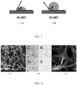
- FIG. 2 is an electron microscope graph of a cross section of a lithium buffer layer in a composite lithium metal negative electrode according to an embodiment of this application.
- FIG. 2-A shows morphology of a porous framework inside the lithium buffer layer.
- FIG. 2-B shows distributions of elements C, N, Zn, and O in a cross section of the lithium buffer layer, and it can be seen that two elements, Zn and O, are densely distributed within the lithium buffer layer.
- FIG. 2-C is an enlarged view of FIG. 1-A , and it can be seen that there is no obvious precipitation of large ZnO particles on the porous framework, indicating that ZnO is uniformly distributed in the porous framework in a form of small particles.
- FIG. 3 is an electron microscope graph of a longitudinal section of a lithium buffer layer according to an embodiment of this application.
- FIG. 3-A shows morphology of a longitudinal section of the lithium buffer layer, and it can be seen that a gradient distribution of a lithiophilic material in a porous framework has no effect on an overall structure of the porous framework.
- FIG. 3-B shows a distribution of element Zn in a longitudinal section of the lithium buffer layer, where a surface with a higher element Zn distribution density is an inner surface of the lithium buffer layer, and a surface with a smaller element Zn distribution density is an outer surface of the lithium buffer layer, and it can be seen that the distribution density of element Zn in the porous framework changes in a continuous gradient.
- a preparation method of a composite lithium metal negative electrode includes the following steps: dissolving a precursor of a lithiophilic material in a solvent to obtain a solution of the precursor of the lithiophilic material; soaking one surface of a porous framework substrate in the solution of the precursor of the lithiophilic material, and taking out the substrate for drying, to obtain a porous framework substrate loaded with the precursor of the lithiophilic material; subjecting the porous framework substrate loaded with the precursor of the lithiophilic material to a sintering treatment and to an optional sulfiding treatment, phosphating treatment, or nitriding treatment, to obtain a lithium buffer layer; and pressing the lithium buffer layer onto at least one surface of the lithium metal, and integrating the surface of the porous framework soaked in the solution of the precursor of the lithiophilic material with the lithium metal, to prepare a composite lithium metal negative electrode.
- the precursor of the lithiophilic material is selected from an organic or inorganic salt containing zinc, aluminum, magnesium, copper, silver or boron.
- the organic salt is selected from bisfluorosulfonimide salt (such as ZnFSI) and/or bistrifluoromethylsulfonimide salt (such as ZnTFSI and AgTFSI); and the inorganic salt is selected from one or more of acetate, nitrate, sulfate, thiosulfate, or meta-aluminate.
- the solvent for dissolving the precursor of the lithiophilic material is selected from one or more of water, ethanol, DMF, or NMP.
- the porous framework substrate is selected from one or more of melamine foam, polyurethane, polyethylene, polystyrene, polyvinyl chloride, polypropylene, polyacetylene, polythiophene, polypyrrole, polyaniline, pure carbon, carbon cloth, or carbon paper, and among them, polyacetylene, polythiophene, polypyrrole, polyaniline, pure carbon, carbon cloth, or carbon paper is inherently conductive.
- the melamine foam, polyurethane, polyethylene, polystyrene, polyvinyl chloride, and polypropylene are not inherently conductive themselves, and can obtain conductivity after high temperature sintering.
- a final conductive porous framework in the composite lithium metal negative electrode may provide sufficient migration channels for deposition and deintercalation of lithium ions, promote induction of the lithium metal deposition by the lithium buffer layer, and improve a cycle life of the battery.
- one surface of the porous framework substrate is soaked in the solution of the precursor of the lithiophilic material for 2-360 minutes.
- the soaking time is 30-60 minutes.
- the soaking time affects diffusion of the solution of the precursor of the lithiophilic material inside the porous framework substrate.
- the range of soaking time provided in this application helps to ensure that a rate of change of lithiophilic gradient in the lithium buffer layer is within an appropriate range, thereby effectively playing a role in improving the cycling performance of the lithium secondary battery.
- the sintering treatment is performed in an inert gas environment.
- a sintering time is preferably 0.5-6 hours. More preferably, a sintering time is 1-2 hours.
- a sintering temperature is preferably 400-2,500°C. More preferably, a sintering temperature is 800-1,000°C. The foregoing sintering time and sintering temperature conditions may make the porous framework achieve better conductivity and nitrogen in the porous framework is not consumed due to excessive sintering.
- an optional sulfiding treatment, phosphating treatment, or nitriding treatment may be further performed.
- the sulfiding treatment performed in some embodiments of this application includes: subjecting a mixture of the lithium buffer layer obtained after the sintering treatment and sulfur powder to sulfiding sintering in an inert gas environment, where preferably, a sulfiding sintering time is 0.5-6 hours, and a sulfiding sintering temperature is 400-1,000°C.
- the phosphating treatment performed in some embodiments of this application includes: subjecting a mixture of the lithium buffer layer obtained after the sintering treatment and phosphorus powder to phosphating sintering in an inert gas environment, where preferably, a phosphating sintering time is 0.5-6 hours, and a phosphating sintering temperature is 400-1,000°C.
- the nitriding treatment performed in some embodiments of this application includes: subjecting the lithium buffer layer obtained after the sintering treatment to nitriding sintering in an N 2 or NH 3 gas environment; where preferably, a nitriding sintering time is 0.5-6 hours, and a nitriding sintering temperature is 400-1,000°C.
- the lithiophilic material in the porous framework may be further transformed from metal oxides or non-metal oxides to metal sulfides, non-metal sulfides, metal phosphides, non-metal phosphides, metal nitrides, or non-metal nitrides.
- the foregoing sulfides, phosphides, and nitrides can also play a lithiophilic role, guiding lithium metal for uniform deposition in the lithium buffer layer of this application.
- a third aspect of this application provides a lithium secondary battery, including the composite lithium metal negative electrode according to the first aspect of this application.
- the lithium secondary battery may include a positive electrode plate, a negative electrode plate, a separator disposed between the positive electrode plate and the negative electrode plate, and an electrolyte.
- the negative electrode plate is the composite lithium metal negative electrode according to the first aspect of this application.
- each of the positive electrode plate, the separator, and the negative electrode plate may be a layer, and may be cut to a target size and then stacked in order.
- the stack may be further wound to a target size to form a battery core, and may be further combined with an electrolyte to form an electrochemical energy storage apparatus.
- the positive electrode plate includes a positive electrode current collector and a positive electrode active substance layer that is provided on at least one surface of the positive electrode current collector.
- the positive electrode active substance layer may be provided on one surface of the positive electrode current collector or on two surfaces of the positive electrode current collector.
- a suitable method for preparing the positive electrode plate For example, the following steps may be included: mixing the positive electrode material, a binder, and a conductive agent to form a slurry, and applying the slurry on the positive electrode current collector.
- the positive electrode active substance may be either a layered structural material to diffuse lithium ions in a two-dimensional space, or a spinel structure to diffuse lithium ions in a three-dimensional space.
- the positive electrode active substance may be selected from one or more of lithium transition metal oxides and compounds obtained by adding other transition metals or non-transition metals or non-metals to the lithium transition metal oxides.
- the positive electrode active substance may be preferably selected from one or more of lithium cobalt oxides, lithium nickel oxides, lithium manganese oxides, lithium nickel manganese oxides, lithium nickel cobalt manganese oxides, lithium nickel cobalt aluminum oxides, and lithium-containing phosphates with an olivine structure.
- a general formula of lithium-containing phosphates with an olivine structure may be LiFe 1-x-y Mn x M' y PO 4 , where 0 ⁇ x ⁇ 1, 0 ⁇ y ⁇ 1, 0 ⁇ x+y ⁇ 1, M' is selected from one or more of transitional metal elements or non-transitional metal elements other than Fe and Mn, and M' is preferably selected from one or more of Cr, Mg, Ti, Al, Zn, W, Nb, and Zr.
- the lithium-containing phosphate with an olivine structure is selected from one or more of lithium iron phosphate, lithium manganese phosphate, and lithium manganese iron phosphate.
- the lithium transition metal oxide is selected from one or more of LiCoO 2 , LiMnO 2 , LiNiO 2 , LiMn 2 O 4 , LiNi x Co y Mn 1-x-y O 2 , LiNi x Co y Al 1-x-y O 2 , and LiNi x Mn 2-x O 4 , where 0 ⁇ x ⁇ 1, 0 ⁇ y ⁇ 1, and 0 ⁇ x+y ⁇ 1.
- the lithium transition metal oxide is selected from one or more of LiCoO 2 , LiNi 1/3 Co 1/3 Mn 1/3 O 2 , LiNi 0.5 Co 0.2 Mn 0.3 O 2 , LiNi 0.6 Co 0.2 Mn 0.2 O 2 , LiNi 0.8 Co 0.1 Mn 0.1 O 2 , LiNi 0.8 Co 0.15 Mn 0.05 O 2 , LiNi 0.8 Co 0.15 Al 0.05 O 2 , LiNi 0.5 Mn 1.5 O 4 , and LiMn 2 O 4.
- LiCoO 2 LiNi 1/3 Co 1/3 Mn 1/3 O 2 , LiNi 0.5 Co 0.2 Mn 0.3 O 2 , LiNi 0.6 Co 0.2 Mn 0.2 O 2 , LiNi 0.8 Co 0.1 Mn 0.1 O 2 , LiNi 0.8 Co 0.15 Mn 0.05 O 2 , LiNi 0.8 Co 0.15 Al 0.05 O 2 , LiNi 0.5 Mn 1.5 O 4 , and LiMn 2 O 4.
- the positive electrode active substance layer may further include a conductive agent and a binder.
- Types or percentages of the conductive agent and the binder are not specifically limited, and may be selected based on an actual requirement.
- the binder typically includes a fluorine-containing polyolefin binder. With respect to the fluorine-containing polyolefin binder, water is usually a good solvent. In other words, the fluorine-containing polyolefin binder usually exhibits good solubility in water.
- the fluorine-containing polyolefin binder may include but is not limited to polyvinylidene fluoride (PVDF), vinylidene fluoride copolymer or modified (for example, modified by carboxylic acid, acrylic acid, or acrylonitrile) derivatives thereof.
- PVDF polyvinylidene fluoride
- the used amount of the binder may not be too high because of the poor conductivity of the binder.
- the mass percentage of the binder in the positive electrode active substance layer is less than or equal to 2 wt%, so as to obtain relatively low impedance of the electrode plate.
- the conductive agent of the positive electrode plate may be various conductive agents suitable for lithium-ion (secondary) batteries in the art, and for example, may include but is not limited to one or more of acetylene black, conductive carbon black, vapor grown carbon fiber (VGCF), carbon nanotubes (CNT), Ketjen black, and the like.
- a weight of the conductive agent may be 1 wt% to 10 wt% of a total mass of the positive electrode material layer. More preferably, a weight ratio of the conductive agent to the positive electrode active substance in the positive electrode plate is greater than or equal to 1.5:95.5.
- the positive electrode current collector is also not limited to any specific type, and may be selected based on an actual requirement.
- the positive electrode current collector may usually be a layer.
- the positive electrode current collector may usually be a structure or a part that can collect current.
- the positive electrode current collector may be various materials suitable for serving as a positive electrode current collector of an electrochemical energy storage apparatus in the art.
- the positive electrode current collector may include but is not limited to a metal foil, and more specifically, may include but is not limited to a nickel foil or an aluminum foil.
- the separator may be various materials suitable for a separator of an electrochemical energy storage apparatus in the art.
- the separator may include but is not limited to one or more of polyethylene, polypropylene, polyvinylidene fluoride, kevlar, polyethylene terephthalate, polytetrafluoroethylene, polyacrylonitrile, polyimide, polyamide, polyester, and natural fibers.
- the electrolyte may be various electrolytes suitable for an electrochemical energy storage apparatus in the art.
- the electrolyte usually includes an electrolytic salt and a solvent
- the electrolytic salt may usually include a lithium salt.
- the lithium salt may be an inorganic lithium salt and/or organic lithium salt, and may specifically include but is not limited to one or more of LiPF 6 , LiBF 4 , LiN(SO 2 F) 2 (LiFSI for short), LiN(CF 3 SO 2 ) 2 (LiTFSI for short), LiClO 4 , LiAsF 6 , LiB(C 2 O 4 ) 2 (LiBOB for short), and LiBF 2 C 2 O 4 (LiDFOB for short).
- a concentration of the electrolyte may be 0.8 mol/L to 1.5 mol/L.
- the solvent may be various solvents suitable for an electrolyte of an electrochemical energy storage apparatus in the art.
- the solvent of the electrolyte is usually a non-aqueous solvent, and preferably, an organic solvent, and may specifically include but is not limited to one or more of ethylene carbonate, propylene carbonate, butylene carbonate, prenyl carbonate, dimethyl carbonate, diethyl carbonate, dipropyl carbonate, ethyl methyl carbonate, or halogenated derivatives thereof.
- FIG. 4 is a three-dimensional diagram of a lithium secondary battery according to a specific embodiment of this application.
- FIG. 5 is an exploded view of the lithium secondary battery in FIG. 4 .
- the lithium secondary battery 5 (hereinafter referred to as the battery cell 5) according to this application includes an outer package 51, an electrode assembly 52, a top cover assembly 53, and an electrolyte (not shown).
- the electrode assembly 52 is accommodated in the housing 51.
- the electrode assemblies 52 is not limited in quantity, and the quantity may be one or more.
- the battery cell 5 in FIG. 4 is a tank type battery, but is not limited thereto in this application.
- the battery cell 5 may be a bag type battery, which means that the housing 51 is replaced with a metal plastic film and the top cover assembly 53 is eliminated.
- lithium secondary batteries may be combined to assemble a battery module, and the battery module may include a plurality of lithium secondary batteries.
- the specific quantity may be adjusted based on a use case and capacity of the battery module.
- FIG. 6 is a three-dimensional diagram of a battery module 4 used as an example. Referring to FIG. 6 , in the battery module 4, a plurality of lithium secondary batteries 5 may be sequentially arranged in a length direction of the battery module 4. Certainly, the plurality of lithium secondary batteries 5 may alternatively be arranged in any other manner. Further, the plurality of lithium secondary batteries 5 may be fixed by using fasteners.
- the battery module 4 may further include a housing with an accommodating space, and the plurality of lithium secondary batteries 5 are accommodated in the accommodating space.
- the battery module may be further assembled into a battery pack, and a quantity of battery modules included in the battery pack may be adjusted based on application and capacity of the battery pack.
- FIG. 7 is a three-dimensional diagram of a battery pack 1 used as an example.
- FIG. 8 is an exploded view of the battery pack in FIG. 7 .
- the battery pack 1 may include a battery box and a plurality of battery modules 4 disposed in the battery box.
- the battery box includes an upper box body 2 and a lower box body 3.
- the upper box body 2 can cover the lower box body 3 to form an enclosed space for accommodating the battery modules 4.
- the plurality of battery modules 4 may be arranged in the battery box in any manner.
- a fourth aspect of this application provides an apparatus, including the lithium secondary battery according to the third aspect of this application, where the lithium secondary battery is used as a power source of the apparatus, or an energy storage unit of the apparatus.
- the apparatus may be, but is not limited to, a mobile device (for example, a mobile phone or a notebook computer), an electric vehicle (for example, a battery electric vehicle, a hybrid electric vehicle, a plug-in hybrid electric vehicle, an electric bicycle, an electric scooter, an electric golf vehicle, or an electric truck), an electric train, a ship, a satellite, an energy storage system, and the like.
- a lithium secondary battery, a battery module, or a battery pack may be selected for the apparatus according to requirements for using the apparatus.
- FIG. 9 is a schematic diagram of an apparatus according to a specific embodiment of this application.
- the apparatus may be a battery electric vehicle, a hybrid electric vehicle, a plug-in hybrid electric vehicle, or the like.
- a battery pack or a battery module may be used.
- the apparatus may be a mobile phone, a tablet computer, a notebook computer, or the like.
- the apparatus usually requires lightness and thinness, and the lithium secondary battery (that is, the secondary battery in this application) may be used as a power source.
- a precursor of a lithiophilic material was dissolved in a solvent to obtain a solution of the precursor of the lithiophilic material; one surface of a porous framework substrate was soaked in the solution of the precursor of the lithiophilic material for several hours; the soaked porous framework substrate was taken out of the solution of the precursor of the lithiophilic material, placed in an oven and dried at 80°C for 12 hours; then the porous framework substrate was placed into a tube furnace and sintered in an inert atmosphere to obtain a lithium buffer layer; and the lithium buffer layer was pressed onto at least one surface of lithium metal, and the surface of the porous framework soaked in the solution of the precursor of the lithiophilic material was integrated with the lithium metal, to prepare a composite lithium metal negative electrode.
- a positive electrode plate, a separator, and an electrolyte were prepared by using the conventional methods in the art.
- Positive electrode plate LiNi 0.8 Co 0.1 Mn 0.1 O 2 , conductive carbon as a conductive agent, and polyvinylidene fluoride (PVDF) as a binder were mixed well at a mass ratio of 96:2:2, to prepare a positive electrode slurry for lithium-ion batteries with a specified viscosity.
- the positive electrode slurry was applied on a current collector aluminum foil which was dried at 85°C and cold pressed, then trimmed, cut, slit, and dried under a vacuum condition at a temperature of 85°C for 4 hours, and welded with a tab, thereby preparing a lithium battery positive electrode plate.
- a polyethylene microporous film with a thickness of 16 ⁇ m was selected as a porous substrate separator material.
- Electrolyte Lithium hexafluorophosphate was dissolved in a mixed solvent composed of ethylene carbonate, dimethyl carbonate, and ethyl methyl carbonate with a volume ratio 1:1:1 of the three components, to obtain a required electrolyte.
- the positive electrode plate, the composite lithium metal negative electrode, and the separator spaced between the positive electrode plate and a lithium supplementing negative electrode plate were wound and assembled, and the electrolyte was injected to prepare a lithium ion battery.
- the lithium ion battery was a soft pack battery with an electrode active area of 40 cm 2 and a battery design capacity of 140 mAh.
- lithium metal was directly used as a negative electrode and matched with a ternary positive electrode without a buffer layer to assemble a lithium metal battery.
- melamine foam with a thickness of 200 ⁇ m was directly sintered at 800 °C for 2 hours, pressed onto a surface of the lithium metal which then was used as a negative electrode and then matched with a ternary positive electrode, to assemble a lithium metal battery.
- each of two pieces of melamine foam with a thickness of 100 ⁇ m was soaked separately in a mixed solution of ethanol and water, with a concentration of zinc acetate at 0.1 M, and in a mixed solution of ethanol and water, with a concentration of zinc acetate at 1 M, and maintained for 720 minutes to ensure that the zinc acetate was fully and uniformly diffused into the melamine foam, without a concentration gradient in a single layer.
- the soaked melamine foam was placed in an oven, dried at 80°C overnight, then placed in a tube furnace, sintered in an inert atmosphere at 800°C for 2 hours, taken out and pressed onto a surface of the lithium metal in sequence.
- the foregoing composite lithium metal negative electrode is matched with a ternary positive electrode to assemble a lithium metal battery.
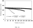
- the specific test method was as follows: at 25 °C, using constant-current charging and constant-current discharging in a charging and discharging voltage range of 2.8-4.3V, with a charging and discharging rate of 0.2C, and an initial capacity of the battery recorded as C 0 , where completion of one full charge and full discharge was recorded as one cycle; and performing charge and discharge according to the foregoing method, testing the capacity of the battery after each cycle until the capacity of the battery is 80% ⁇ C 0 , and recording the number of cycles in this case.
- Example 1 Code Porous substrate Substrate thickness Soaking solution Soaking solute Soaking time Sintering temperature Carbonation time
- Example 2 Melamine foam 200 ⁇ m Water/ethanol Zinc acetate 1 h 800°C 2 h
- Example 2 Melamine foam 200 ⁇ m Water/ethanol Magnesium acetate 1 h 800°C 2 h
- Example 3 Melamine foam 200 ⁇ m Water/ethanol Zinc nitrate 1 h 800°C 2 h
- Example 4 Melamine foam 200 ⁇ m Water/ethanol Aluminum nitrate 1 h 800°C 2 h
- Example 5 Melamine foam 200 ⁇ m Water/ethanol Silver nitrate 1 h 800°C 2 h
- Example 6 Melamine foam 200 ⁇ m DMF Zinc acetate 1 h 800°C 2 h
- Example 7 Melamine foam 200 ⁇ m NMP Zinc acetate 1 h 800°C 2 h
- Example 8 Melamine foam 200 ⁇ m Acetone Zinc acetate 1 h
- Examples 1 to 13 showed that adding the lithium buffer layer of this application on a surface of the lithium metal negative electrode for the lithium secondary battery has improved the battery cycling performance of the lithium secondary battery. It can be seen from Table 1 that different precursors of the lithiophilic material were selected for preparation of the solutions of the precursors of the lithiophilic material in Examples 1 to 5, respectively; different solvents were selected for preparation of the solutions of the precursors of the lithiophilic material in Examples 1 and 6 to 9, respectively; and different porous framework substrates were selected in Examples 1 and 10 to 13, respectively.
- the lithium buffer layers prepared by using different types of lithiophilic materials and different types of porous frameworks can induce uniform deposition of the lithium metal in the lithium buffer layer, and prevent lithium ions from gaining electrons on the outer surface of the lithium buffer layer, thereby improving the cycling performance of the lithium secondary battery.
- FIG. 10 shows the cycling performance of the lithium secondary battery in Example 1 and Comparative Examples 1 and 2. It can be seen from FIG. 10 that the cycling performance in Example 1 is significantly better than that in Comparative Examples 1 and 2.
- Comparative Example 3 a buffer layer with a discontinuous lithiophilic gradient was formed on a surface of the lithium metal negative electrode.
- the buffer layer added on the surface of the lithium metal negative electrode was composed of two porous framework layers with different distribution densities of a lithiophilic material. During cycling of the battery, uneven deposition of the lithium metal in the porous framework layer with a same distribution density of the lithiophilic material was still inevitable.
- Examples 1 and 14 to 19 showed influence of the soaking time of one surface of the porous framework substrate in the solution of the precursor of the lithiophilic material on technical effects of this application.
- Example 14 When the soaking time was too short (as in Example 14), there was no enough time for the solution of the precursor of the lithiophilic material to diffuse into the porous framework substrate to exert an inhibition effect on the growth of lithium dendrites in the lithium metal negative electrode, resulting in only a slight improvement in the cycling performance of the lithium secondary battery compared to that in Example 2 without an additional lithium buffer layer.
- the solution of the precursor of the lithiophilic material diffused through one surface of the porous framework substrate to the interior of the porous framework substrate and gradually formed a continuous concentration distribution gradient in the porous framework substrate, which also resulted in a continuous gradient-reduced lithiophilicity in the lithium buffer layer in the composite lithium metal negative electrode.
- the inhibition effect of the lithium buffer layer on the lithium dendrites in the lithium metal negative electrode and the induced deposition effect of the lithium buffer layer on lithium metal were gradually obvious, and the improvement effect on the cycling performance of lithium secondary batteries also became significant.
- Example 1 the soaking time of the porous framework substrate in the solution of the precursor of the lithiophilic material was 1 hour, and the lithium secondary battery had a good cycling performance. If the soaking time was further increased, the solution of the precursor of the lithiophilic material may continue to diffuse and penetrate into the porous framework substrate, which led to the gradual disappearance of the lithiophilic gradient in the porous framework, and made the improvement effect on the cycling performance of the lithium secondary battery also became weak instead. For example, in Example 19, the soaking time of the porous framework substrate in the solution of the precursor of the lithiophilic material was 720 minutes, and the improvement effect on the cycling performance of the lithium secondary battery was not as good as that in Example 1.
- one surface of the porous framework substrate was soaked in the solution of the precursor of the lithiophilic material preferably for 2-360 minutes, and more preferably, for 30-60 minutes.
- Examples 1 and 20 to 25 showed influence of the temperature conditions, under which the porous framework substrate loaded with the precursor of the lithiophilic material was sintered in an inert atmosphere, on technical effects of this application.
- Example 1 the sintering temperature of the porous framework substrate loaded with the solution of the precursor of the lithiophilic material in an inert atmosphere was 800°C, and the improvement effect on the cycling performance of lithium secondary battery was significant.
- the temperature at which the porous framework substrate loaded with the precursor of the lithiophilic material was sintered was preferably 400-2,500°C, and more preferably, 800-1,000°C.
- Examples 1 and 26 to 31 showed influence of the sintering time, at which the porous framework substrate loaded with the precursor of the lithiophilic material was sintered in an inert atmosphere, on technical effects of this application.
- Example 1 the sintering time of the porous framework substrate loaded with the solution of the precursor of the lithiophilic material in an inert atmosphere was 2 hours, and the improvement effect on the cycling performance of lithium secondary battery was significant.
- the porous framework substrate loaded with the precursor of the lithiophilic material was sintered preferably for 0.5-6 hours, and more preferably, for 1-2 hours.
- Examples 1 and 32 to 38 showed influence of the thickness of the porous framework substrate on technical effects of this application.
- the strength of the porous framework substrate was also improved, which was conducive to the long cycling of the battery, and the cycling performance of the lithium secondary battery was further improved.
- the thicker the porous framework substrate was, the better the result would be.
- this porous framework substrate was used to prepare the lithium buffer layer added on the lithium metal negative electrode, and the battery was assembled by using the lithium metal negative electrode, the electrolyte was consumed seriously due to the excessive thickness of the lithium buffer layer, and the improvement effect of the porous framework substrate on the cycling performance of the lithium secondary battery was not as good as that in Example 1.
- the thickness of the porous framework was 1-10,000 ⁇ m, and preferably, 50-1,000 ⁇ m.
- a difference from Example 1 was only that: a mixture of the lithium buffer layer obtained after the sintering treatment and sulfur powder was subjected to sulfiding sintering in an inert gas environment, and it was ensured that an internal environment for sulphation was closed.
- a difference from Example 1 was only that: a mixture of the lithium buffer layer obtained after the sintering treatment and phosphorus powder was subjected to phosphating sintering in an inert gas environment, and it was ensured that an internal environment for phosphation was closed.
- Example 1 A difference from Example 1 was only that: the lithium buffer layer obtained after the sintering treatment was subj ected to nitriding sintering in an N 2 or NH 3 gas environment.
- the lithiophilic material in the porous framework was further transformed from metal oxides or non-metal oxides to metal sulfides, non-metal sulfides, metal phosphides, non-metal phosphides, metal nitrides, or non-metal nitrides, and that the technical effects of inducing the uniform deposition of the lithium metal in the lithium buffer layer, inhibiting the growth of lithium dendrites, and improving the cycle life of lithium secondary batteries can also be achieved.
- Table 4 shows influence of the contact angle of molten lithium on the outer surface of the lithium buffer layer, the contact angle of molten lithium on the inner surface of the lithium buffer layer, and the difference between the contact angles of molten lithium on the two surfaces, on technical effects of this application.
- the contact angle of molten lithium on the inner surface of the lithium buffer layer was preferably 0°-90°, and in this case, the inner surface of the lithium buffer layer had good lithiophilicity.
- the contact angle of molten lithium on the outer surface of the lithium buffer layer was preferably 90°-180°, and in this case, the outer surface of the lithium buffer layer had weak lithiophilicity or was lithiophobic. Therefore, the lithium buffer layer may induce the lithium metal to spontaneously deposit from the lithiophobic side to the lithiophilic side of the lithium buffer layer and finally uniformly deposit inside the lithium buffer layer.
- an angle difference between the contact angle of molten lithium on the outer surface of the lithium buffer layer and the contact angle of molten lithium on the inner surface of the lithium buffer layer was 10°-180°, and preferably, 45°-135°.
- the angle difference between the contact angles of molten lithium on the outer surface and the inner surface of the lithium buffer layer was less than 10°, a rate of change of the lithiophilic gradient between the inner and outer surfaces was too small, lack of driving force to induce the lithium metal to deposit from the lithiophobic side to the lithiophilic side.
- the angle difference of the contact angles of molten lithium between the outer surface and the inner surface of the lithium buffer layer was 45°-135°, so that an obvious lithiophilic gradient change between the inner and outer surfaces can effectively drive and induce deposition of the lithium metal from the lithiophobic side to the lithiophilic side, improve deposition utilization of an internal space of the porous framework of the lithium buffer layer, and effectively suppress the growth of lithium dendrites, effectively improving the cycling performance of the lithium secondary battery.
Landscapes
- Chemical & Material Sciences (AREA)
- Engineering & Computer Science (AREA)
- Chemical Kinetics & Catalysis (AREA)
- Electrochemistry (AREA)
- General Chemical & Material Sciences (AREA)
- Manufacturing & Machinery (AREA)
- Materials Engineering (AREA)
- Dispersion Chemistry (AREA)
- Battery Electrode And Active Subsutance (AREA)
Applications Claiming Priority (1)
| Application Number | Priority Date | Filing Date | Title |
|---|---|---|---|
| PCT/CN2020/099371 WO2022000292A1 (zh) | 2020-06-30 | 2020-06-30 | 复合金属锂负极、其制备方法、锂二次电池及装置 |
Publications (2)
| Publication Number | Publication Date |
|---|---|
| EP4170749A1 true EP4170749A1 (de) | 2023-04-26 |
| EP4170749A4 EP4170749A4 (de) | 2023-10-11 |
Family
ID=79317287
Family Applications (1)
| Application Number | Title | Priority Date | Filing Date |
|---|---|---|---|
| EP20943700.3A Pending EP4170749A4 (de) | 2020-06-30 | 2020-06-30 | Verbund-lithiummetall-negativelektrode, herstellungsverfahren dafür und lithiumsekundärbatterie und vorrichtung |
Country Status (4)
| Country | Link |
|---|---|
| US (1) | US20230107697A1 (de) |
| EP (1) | EP4170749A4 (de) |
| CN (1) | CN115461891B (de) |
| WO (1) | WO2022000292A1 (de) |
Families Citing this family (18)
| Publication number | Priority date | Publication date | Assignee | Title |
|---|---|---|---|---|
| KR102923225B1 (ko) * | 2021-03-17 | 2026-02-04 | 현대자동차주식회사 | 활물질이 없는 전고체 전지용 복합 음극 및 이의 제조방법 |
| CN114551788A (zh) * | 2022-02-25 | 2022-05-27 | 四川大学 | 一种离子场/电场可控三维金属负极及其制备方法 |
| CN114551813B (zh) * | 2022-02-28 | 2024-02-02 | 华中科技大学 | 一种金属锂复合电极、制备方法、应用及电池 |
| CN115132958B (zh) * | 2022-07-20 | 2025-07-04 | 上海国轩新能源有限公司 | 一种具有界面修饰层的锂金属负极及其制备方法 |
| CN116666563A (zh) * | 2022-09-26 | 2023-08-29 | 荣耀终端有限公司 | 一种负极极片、其制备方法、锂离子电池及电子设备 |
| CN115528213B (zh) * | 2022-10-31 | 2024-02-09 | 南昌大学 | 一种锂金属复合负极材料及其制备方法 |
| CN115954440A (zh) * | 2023-02-07 | 2023-04-11 | 深圳先进技术研究院 | 一种表面改性后的锂金属负极的制备方法、锂金属负极及锂金属电池 |
| CN115995564B (zh) * | 2023-02-24 | 2026-01-30 | 西北工业大学 | 多梯度柔性金属二次电池负极集流体及其制备方法和应用 |
| WO2024192593A1 (zh) * | 2023-03-17 | 2024-09-26 | 宁德时代新能源科技股份有限公司 | 集流体及其制备方法、电极片、二次电池及用电装置 |
| CN116314736B (zh) * | 2023-03-17 | 2025-09-05 | 深圳市研一新材料有限责任公司 | 一种锂复合材料及其制备方法与应用 |
| CN119069712B (zh) * | 2023-05-31 | 2026-01-06 | 比亚迪股份有限公司 | 集流体及其制备方法和无负极锂金属电池 |
| CN116936815B (zh) * | 2023-09-18 | 2024-02-27 | 宁德时代新能源科技股份有限公司 | 负极集流体及其制备方法、负极极片、锂金属电池及用电装置 |
| CN117154021B (zh) * | 2023-09-25 | 2025-09-05 | 中国长江三峡集团有限公司 | 一种三维锂金属负极及其制备方法、锂离子电池 |
| CN118610467B (zh) * | 2024-08-08 | 2024-11-15 | 深圳市贝特瑞新能源技术研究院有限公司 | 锂金属负极材料及其制备方法、锂金属复合负极、锂离子电池 |
| CN121641851A (zh) * | 2024-08-30 | 2026-03-10 | 宁德时代新能源科技股份有限公司 | 多孔负极极片及其制备方法、电池单体、电池装置和用电装置 |
| CN119208542A (zh) * | 2024-09-25 | 2024-12-27 | 北京航空航天大学 | 一种具有体积膨胀自适应性的锂金属负极及其制备方法和应用 |
| CN119419389B (zh) * | 2024-11-15 | 2025-08-29 | 有研(广东)新材料技术研究院 | 一种全固态锂金属电池界面保护层及其制备方法和应用 |
| CN119481083B (zh) * | 2025-01-14 | 2025-04-08 | 湖南镓睿科技有限公司 | 一种锂金属负极集流体及其制备方法、锂金属电池 |
Family Cites Families (9)
| Publication number | Priority date | Publication date | Assignee | Title |
|---|---|---|---|---|
| JP2010199083A (ja) * | 2010-04-28 | 2010-09-09 | Sharp Corp | リチウム二次電池 |
| DE102016116632A1 (de) * | 2016-09-06 | 2018-03-08 | Audi Ag | Gasdiffusionselektrode sowie Brennstoffzelle mit einer solchen |
| KR102363966B1 (ko) * | 2017-11-30 | 2022-02-16 | 주식회사 엘지에너지솔루션 | 리튬 이차전지 및 그 제조방법 |
| CN108365200A (zh) * | 2018-02-11 | 2018-08-03 | 清华大学 | 一种复合锂金属负极的制备方法 |
| CN109546141A (zh) * | 2018-12-14 | 2019-03-29 | 蜂巢能源科技有限公司 | 锂金属复合电极及其制备方法、锂离子电池 |
| CN109713224B (zh) * | 2018-12-28 | 2021-12-21 | 蜂巢能源科技有限公司 | 复合锂金属负极及制备方法、锂离子电池 |
| CN209747642U (zh) * | 2019-05-28 | 2019-12-06 | 安徽盟维新能源科技有限公司 | 锂铜复合电极及二次电池 |
| CN110993954B (zh) * | 2019-11-12 | 2021-06-22 | 北京理工大学 | 一种锂金属二次电池负极集流体及其制备方法 |
| CN110931712B (zh) * | 2019-12-10 | 2021-01-01 | 清华大学 | 一种具有填充物的复合金属锂负极及其制备方法 |
-
2020
- 2020-06-30 WO PCT/CN2020/099371 patent/WO2022000292A1/zh not_active Ceased
- 2020-06-30 CN CN202080100246.XA patent/CN115461891B/zh active Active
- 2020-06-30 EP EP20943700.3A patent/EP4170749A4/de active Pending
-
2022
- 2022-12-07 US US18/062,578 patent/US20230107697A1/en active Pending
Also Published As
| Publication number | Publication date |
|---|---|
| US20230107697A1 (en) | 2023-04-06 |
| WO2022000292A1 (zh) | 2022-01-06 |
| CN115461891A (zh) | 2022-12-09 |
| CN115461891B (zh) | 2025-04-18 |
| EP4170749A4 (de) | 2023-10-11 |
Similar Documents
| Publication | Publication Date | Title |
|---|---|---|
| US20230107697A1 (en) | Composite lithium metal negative electrode, preparation method thereof, lithium secondary battery, and apparatus | |
| EP3800706B1 (de) | Negative elektrode sowie sekundärbatterie und vorrichtung damit | |
| ES2985194T3 (es) | Material de electrodo positivo para batería secundaria y batería secundaria de litio que comprende el mismo | |
| EP4170755A1 (de) | Positivelektrodenmaterial, positivelektrodenpolteil, lithiumsekundärbatterie, batteriemodul, batteriepack und vorrichtung | |
| US9882207B2 (en) | Lithium-ion secondary battery | |
| CN114788044A (zh) | 二次电池、其制备方法、及其相关的电池模块、电池包和装置 | |
| KR101543939B1 (ko) | 비수 전해액 2차 전지 | |
| EP4597630A1 (de) | Negativelektrodenaktivmaterial, negativelektrodenfolie damit, elektrochemische vorrichtung und elektrische vorrichtung | |
| KR20240068801A (ko) | 이차 전지 및 이차 전지를 포함하는 장치 | |
| KR101488576B1 (ko) | 정극 활물질의 평가 방법 | |
| JP2008262768A (ja) | リチウムイオン二次電池 | |
| EP4394923A1 (de) | Negativelektrodenaktivmaterial und herstellungsverfahren dafür, sekundärbatterie mit negativelektrodenaktivmaterial und elektrische vorrichtung | |
| EP4322259A1 (de) | Positivelektrodenmaterial, herstellungsverfahren dafür und sekundärbatterie damit | |
| KR20230031297A (ko) | 애노드 극판, 이차 전지, 전지 모듈, 전지 팩 및 전기 장치 | |
| CN115832187B (zh) | 电极及其制备方法、二次电池、电池模块、电池包和用电装置 | |
| EP4503165A1 (de) | Sekundärbatterie und elektrische vorrichtung | |
| EP4362137A1 (de) | Kohlenstoffmaterial und herstellungsverfahren dafür und verwendung davon, negativelektrodenfolie, sekundärbatterie und elektrische vorrichtung | |
| JP2005259617A (ja) | リチウムイオン二次電池 | |
| US9312568B2 (en) | Lithium secondary battery | |
| EP4546460A1 (de) | Sekundärbatterie, batteriemodul, batteriepack und elektrische vorrichtung | |
| US20250286138A1 (en) | Nonaqueous electrolyte solution, lithium secondary battery containing same, and electrical device | |
| CN120999134A (zh) | 锂离子电池 | |
| CN117529832A (zh) | 二次电池和用电装置 | |
| CN112186177A (zh) | 非水电解质二次电池及正极活性物质 | |
| EP4425604A1 (de) | Sekundärbatterie und herstellungsverfahren dafür sowie elektrische vorrichtung |
Legal Events
| Date | Code | Title | Description |
|---|---|---|---|
| STAA | Information on the status of an ep patent application or granted ep patent |
Free format text: STATUS: THE INTERNATIONAL PUBLICATION HAS BEEN MADE |
|
| PUAI | Public reference made under article 153(3) epc to a published international application that has entered the european phase |
Free format text: ORIGINAL CODE: 0009012 |
|
| STAA | Information on the status of an ep patent application or granted ep patent |
Free format text: STATUS: REQUEST FOR EXAMINATION WAS MADE |
|
| 17P | Request for examination filed |
Effective date: 20230120 |
|
| AK | Designated contracting states |
Kind code of ref document: A1 Designated state(s): AL AT BE BG CH CY CZ DE DK EE ES FI FR GB GR HR HU IE IS IT LI LT LU LV MC MK MT NL NO PL PT RO RS SE SI SK SM TR |
|
| DAV | Request for validation of the european patent (deleted) | ||
| DAX | Request for extension of the european patent (deleted) | ||
| A4 | Supplementary search report drawn up and despatched |
Effective date: 20230906 |
|
| RIC1 | Information provided on ipc code assigned before grant |
Ipc: H01M 4/02 20060101ALN20230901BHEP Ipc: H01M 10/052 20100101ALI20230901BHEP Ipc: H01M 10/0525 20100101ALI20230901BHEP Ipc: H01M 4/80 20060101ALI20230901BHEP Ipc: H01M 4/62 20060101ALI20230901BHEP Ipc: H01M 4/36 20060101ALI20230901BHEP Ipc: H01M 4/04 20060101ALI20230901BHEP Ipc: H01M 4/38 20060101ALI20230901BHEP Ipc: H01M 4/1395 20100101ALI20230901BHEP Ipc: H01M 4/134 20100101AFI20230901BHEP |
|
| RAP1 | Party data changed (applicant data changed or rights of an application transferred) |
Owner name: CONTEMPORARY AMPEREX TECHNOLOGY(HONG KONG) LIMITED |