EP4169549A1 - Drahtloses kommunikationsmodul für medizinische fluidpumpe - Google Patents
Drahtloses kommunikationsmodul für medizinische fluidpumpe Download PDFInfo
- Publication number
- EP4169549A1 EP4169549A1 EP22201669.3A EP22201669A EP4169549A1 EP 4169549 A1 EP4169549 A1 EP 4169549A1 EP 22201669 A EP22201669 A EP 22201669A EP 4169549 A1 EP4169549 A1 EP 4169549A1
- Authority
- EP
- European Patent Office
- Prior art keywords
- circuit board
- medical fluid
- fluid pump
- board
- communication circuit
- Prior art date
- Legal status (The legal status is an assumption and is not a legal conclusion. Google has not performed a legal analysis and makes no representation as to the accuracy of the status listed.)
- Pending
Links
Images

Classifications
-
- H—ELECTRICITY
- H01—ELECTRIC ELEMENTS
- H01Q—ANTENNAS, i.e. RADIO AERIALS
- H01Q1/00—Details of, or arrangements associated with, antennas
- H01Q1/12—Supports; Mounting means
- H01Q1/22—Supports; Mounting means by structural association with other equipment or articles
-
- A—HUMAN NECESSITIES
- A61—MEDICAL OR VETERINARY SCIENCE; HYGIENE
- A61M—DEVICES FOR INTRODUCING MEDIA INTO, OR ONTO, THE BODY; DEVICES FOR TRANSDUCING BODY MEDIA OR FOR TAKING MEDIA FROM THE BODY; DEVICES FOR PRODUCING OR ENDING SLEEP OR STUPOR
- A61M5/00—Devices for bringing media into the body in a subcutaneous, intra-vascular or intramuscular way; Accessories therefor, e.g. filling or cleaning devices, arm-rests
- A61M5/14—Infusion devices, e.g. infusing by gravity; Blood infusion; Accessories therefor
- A61M5/142—Pressure infusion, e.g. using pumps
-
- H—ELECTRICITY
- H01—ELECTRIC ELEMENTS
- H01Q—ANTENNAS, i.e. RADIO AERIALS
- H01Q1/00—Details of, or arrangements associated with, antennas
- H01Q1/52—Means for reducing coupling between antennas; Means for reducing coupling between an antenna and another structure
- H01Q1/526—Electromagnetic shields
-
- H—ELECTRICITY
- H01—ELECTRIC ELEMENTS
- H01Q—ANTENNAS, i.e. RADIO AERIALS
- H01Q21/00—Antenna arrays or systems
- H01Q21/06—Arrays of individually energised antenna units similarly polarised and spaced apart
-
- A—HUMAN NECESSITIES
- A61—MEDICAL OR VETERINARY SCIENCE; HYGIENE
- A61M—DEVICES FOR INTRODUCING MEDIA INTO, OR ONTO, THE BODY; DEVICES FOR TRANSDUCING BODY MEDIA OR FOR TAKING MEDIA FROM THE BODY; DEVICES FOR PRODUCING OR ENDING SLEEP OR STUPOR
- A61M2205/00—General characteristics of the apparatus
- A61M2205/35—Communication
- A61M2205/3546—Range
Definitions
- the present disclosure relates to a medical fluid pump, in particular in the form of an infusion pump or syringe pump, with a wireless communication module in the form of a communication circuit board.
- Fluid pumps in particular syringe pumps and infusion pumps or peristaltic pumps, are widely used in medicine to supply a patient with a defined dose of medication.
- Such medical fluid pumps have been equipped with more and more smart functions over the past few years. These smart functions are implemented using additional circuit boards or chips, which are mostly designed as purchased parts. These additional circuit boards or chips are provided and designed to be mounted flat on a main circuit board or a mainboard. As a result, the main circuit board needs to be made larger than the case where smart functions are not provided in the medical fluid pump. Such an enlarged main circuit board requires a larger base area, with the result that the medical fluid pump increases in size and thus takes up more space. As a result, the accessibility of a patient who is being supplied with the medical fluid pump is impaired for medical staff.
- the object and aim of the present invention is therefore to provide a medical fluid pump which is equipped with smart functions without taking up more space and without having the disadvantages discussed above.
- the medical fluid pump preferably in the form of an infusion pump or syringe pump, contains a circuit board, which is equipped with the essential control devices of the medical fluid pump, namely at least with the control device of a motor of the medical fluid pump, and a wireless communication module in the form of a communication circuit board.
- the communication circuit board is arranged essentially perpendicularly or orthogonally to the circuit board.
- the medical fluid pump has a circuit board, which can also be referred to as a main board or main circuit board.
- the control devices that are essential for the function of the medical fluid pump are implemented on this circuit board.
- the essential control devices for the function of the medical fluid pump include at least the control device of the motor of the fluid pump, which is responsible for the application of the fluid or the medicament.
- the control device for the motor of the fluid pump can also be used to monitor the motor on the fluid pump on the circuit board.
- the medical fluid pump includes the wireless communication module in the form of the communication board.
- the communication circuit board contains various devices that enable wireless communication of data, preferably by means of WLAN and/or Bluetooth and/or any wireless radio technology between the medical fluid pump and an external device.
- the communication board is arranged essentially perpendicularly or orthogonally to the two-dimensional extent of the board.
- the angle between the two-dimensional extension of the communication circuit board and the two-dimensional extension of the circuit board is between 80° and 100°, preferably between 85° and 95° and particularly preferably 90°.
- the communication circuit board in particular is one of the smart circuit boards that is required for the smart functions and requires a considerable amount of space.
- the base area of the communication board projected onto the board is significantly reduced and the board can be made more compact than in the case in which the Communication circuit board is aligned flat / parallel to the circuit board.
- This can ensure that the dimensions of the medical fluid pump do not change compared to the case in which no wireless communication module is provided in the medical fluid pump.
- air can circulate better around the communication circuit board than in the case of the planar/parallel orientation. This improves the cooling of the communication circuit board.
- Such an orientation of the communication circuit board is in direct contrast to the otherwise usual orientation of the communication circuit board.
- the communication circuit board can be enclosed or surrounded by a (shield) cage that is metallic or contains metallic elements.
- the communication circuit board is surrounded by metal sheets or a metal mesh cage or a plastic cage which contains metal elements, for example in the form of metal particles.
- the communication circuit board is shielded in particular against high-frequency electromagnetic fields with the aid of metallic elements.
- radiated interference from the communications board is also shielded.
- the cage can be connected to the communication circuit board at individual points spaced apart from one another, in particular at four points.
- the cage is connected to the communication circuit board at four connection points, which are preferably located in the four corners of the communication circuit board.
- the cage can be connected to the communication circuit board at two points in a materially joined manner, in particular by soldering, and can be connected to the communication circuit board in a non-positive manner at two points, in particular by clamping.
- the cage is integrally connected to the communication circuit board at two connection points located on the same edge of the communication circuit board. At two other connection points of the Communication board, which are located on another edge of the communication board, the cage is frictionally connected to the communication board.
- connection by means of a frictional connection enables a displacement of the frictionally connected connection points in the event of forces occurring between the cage and the communication circuit board if the force occurring exceeds a certain threshold value. In this way it is ensured that in the event of a possible expansion of the metal cage, for example due to a temperature increase, no excessively high voltages are introduced into the communication circuit board, which could damage the communication circuit board.
- the cage can be connected to a ground potential of the circuit board.
- the cage is electrically conductively connected to the ground (GND) of the circuit board.
- the communication circuit board can be connected to a plurality of, in particular two, antennas.
- the communication board has MIMO (Multiple Input Multiple Output) interfaces.
- MIMO Multiple Input Multiple Output
- This enables coding methods that use not only a temporal dimension but also a spatial dimension for information transmission. This significantly improves both the quality in the form of the bit error rate and the data rate of the wireless connection.
- the antenna and the communication board separately, it is possible to dispose the antennas at positions suitable for the transmission performance.
- the multiple, in particular two, antennas can be arranged orthogonally to one another.
- the spatial orientation of the antennas differs from one another by essentially 90°.
- the transmission capacity can be increased thanks to the orthogonal directional characteristics of the antennas.
- a coverage area can be increased by the radiation characteristics of the antennas due to the orthogonal arrangement.
- the multiple, in particular two, antennas can be connected to the communication circuit board by means of cables, the cable lengths of the cables which connect the communication circuit board to the antennas being identical.
- identical cables are used to connect the antennas to the communication circuit board.
- the cable length is preferably 175 mm. On the one hand, this enables a reduction in the number of spare parts and simplifies assembly of the medical fluid pump. On the other hand, the identical cable length ensures that there are no transit time differences between the antennas and the communication board.
- the cables are laid on the circuit board using clips. The cables and thus the antennas are connected to the ground potential of the circuit board via the clips.
- the antennas can be arranged at a distance from one another which corresponds to a multiple of a quarter, in particular a multiple of a half, wavelength of the transmission frequency of the antenna.
- the transmission frequency of the antennas is 2.4 GHz and/or 5 GHz.
- the wavelength is 12.5 cm for 2.4 GHz and 6 cm for 5 GHz.
- the distance between the antennas is therefore a multiple of 3.125 cm or a multiple of 3 cm. Such an arrangement of the antennas relative to one another minimizes mutual interference between the antennas.
- the communications board is thermally coupled to the circuit board.
- the communication circuit board is connected to the circuit board by means of a thermally conductive component. Due to the high metal content of the board and the large surface area of the board, the board acts as a heat sink for the communication board and prevents the communication board from overheating.
- the communications board can operate independently of the circuit board.
- the board and the communication board exchange data packets, with both the board and the communication board functioning independently of each other. This ensures that in the event of a failure or a temporary disruption in the communication circuit board, the essential functions of the medical fluid pump that are controlled by the circuit board can continue to be performed.
- the essential functions of the medical fluid pump can be controlled wirelessly via the communication circuit board.
- a medication application can be started, paused or stopped.
- the communication circuit board can wirelessly transmit information about faults in the function of the circuit board, for example to a practitioner and/or the manufacturer of the fluid pump.
- a software update for the medical fluid pump and/or the drug database stored on the medical fluid pump can be transmitted wirelessly to the medical fluid pump via the communication circuit board.
- FIG. 1 shows an interior view of a medical fluid pump 2 according to the invention with a substantially rectangular housing 4, drive components 5 and a front flap 6 attached to a front side of the housing 4 of the medical fluid pump 2, which is connected via a connecting cable 7.
- the medical fluid pump 2 contains a circuit board/mainboard 8 in the housing 4, which is equipped with the essential control devices of the medical fluid pump 2, namely at least with the control device of a motor of the medical fluid pump 2, and a wireless communication module in the form of a communication circuit board 10.
- the communication circuit board 10 is arranged essentially perpendicularly or orthogonally to the circuit board 8 . In other words, a narrow side of the communication circuit board 10 contacts the surface of the circuit board 8.
- the communication circuit board 10 is arranged essentially in the middle, based on a width direction of the housing 4.
- the communication circuit board 10 is surrounded by a metallic shielding cage 12 .
- Communications board 10 is connected to antennas 16, 26 by cables 14.
- the antennas 16 , 26 are each arranged on side walls of the housing 4 of the medical fluid pump 2 .
- the distance between the antennas 16, 26 is a multiple of a quarter or half a wavelength of the transmission frequency of the antennas 16, 26.
- the shielding cage 12 encloses the communication circuit board 10 from six sides and prevents electromagnetic fields or radiation from influencing or interfering with the function of the communication circuit board 10.
- the shield cage 12 consists of sheet metal.
- the screen cage 12 has three feet 17 which are each provided with a through hole 18 .
- the shielding cage 12 is connected to the circuit board 8 through the through-holes 18 by means of screws 20 . By providing three feet 17, the screen cage 12 is fixed in a statically determined manner.
- the shielding cage 12 has a first connection opening (not shown) on the side facing the circuit board 8 .
- the communication circuit board 10 is connected to the circuit board 8 by means of a circuit board plug through the first connection opening.
- the shielding cage 12 has a second connection opening 21 in a side surface of the shielding cage 12 oriented orthogonally to the circuit board 8 .
- the cables 14 which connect the communication circuit board 10 to the antennas 16 are connected to the communication circuit board 10 through the second connection opening 21 .
- the shielded cage 12 also has ventilation slits 22 which improve air exchange between an interior of the shielded cage 12 and an interior of the housing 4 of the medical fluid pump, so that warm air is prevented from accumulating in the shielded cage 12 .
- Clamping elements 25 are formed in two corner sections of the shielding cage 12 that face away from the circuit board 8 in a mounted state, which connect the shielding cage 12 to the communication circuit board 10 in a non-positive manner.
- the shielding cage 12 is cohesively connected to the communication circuit board 10 in two corner sections of the shielding cage 12 that face the circuit board 8 in a mounted state.
- FIG. 3 shows the communication board 10 in the shield cage 12 on the board 8 and a first antenna 16 connected by cable 14.
- the first antenna 16 is aligned orthogonally to the board 8 and on an inside of the side wall of Housing 4 of the medical fluid pump 2 attached.
- a vertical antenna receptacle 24 is formed in the housing 4 to accommodate the first antenna 16 and accommodates the antenna 16 in a form-fitting manner.
- the vertical antenna mount 24 is formed by two rails that extend orthogonally to the circuit board 8 in a direction. The rails are formed in one piece with the housing 4 .
- the 4 shows a further section of the interior of the housing 4 of the medical fluid pump with the circuit board 8, the cables 14 and a second antenna 26, the communication circuit board 10 having been omitted for the sake of clarity.
- the second antenna 26 is aligned parallel to the circuit board 8 and is thus oriented offset by 90° to the first antenna 16 .
- the second antenna 26 is attached to an inner side of the side wall of the medical fluid pump housing 4 opposite to the first antenna.
- a horizontal antenna receptacle 28 is formed in the housing 4 to accommodate the second antenna 26 and accommodates the antenna 26 in a form-fitting manner.
- the horizontal antenna mount 28 is formed by two rails that extend orthogonally to the circuit board 8 in a direction. The rails are formed in one piece with the housing 4 .
- Both the first antenna 16 and the second antenna 26 are connected to the communication circuit board 10 by means of the cables 14 .
- the cable 14 between the communication circuit board 10 and the first antenna 16 and the cable 14 between the communication circuit board and the second antenna 26 have identical lengths.
- the cables 14 are fixed on the circuit board 8 by means of cable clips 30 .
- the antennas 16 , 26 are connected to a ground potential of the circuit board 8 by means of the cable clips 30 .
Landscapes
- Health & Medical Sciences (AREA)
- Vascular Medicine (AREA)
- Engineering & Computer Science (AREA)
- Anesthesiology (AREA)
- Biomedical Technology (AREA)
- Heart & Thoracic Surgery (AREA)
- Hematology (AREA)
- Life Sciences & Earth Sciences (AREA)
- Animal Behavior & Ethology (AREA)
- General Health & Medical Sciences (AREA)
- Public Health (AREA)
- Veterinary Medicine (AREA)
- Physics & Mathematics (AREA)
- Electromagnetism (AREA)
- Infusion, Injection, And Reservoir Apparatuses (AREA)
Abstract
Description
- Die vorliegende Offenbarung betrifft eine medizinische Fluidpumpe, insbesondere in Form einer Infusionspumpe oder Spritzenpumpe, mit einem drahtlosen Kommunikationsmodul in Form einer Kommunikationsplatine.
- In der Medizin werden verbreitet Fluidpumpen, insbesondere Spritzenpumpen und Infusionspumpen bzw. Schlauchpumpen zur Versorgung eines Patienten mit einer definierten Dosis an Medikamenten eingesetzt.
- Solche medizinischen Fluidpumpen wurden im Laufe der letzten Jahre mit immer mehr Smartfunktionen ausgerüstet. Diese Smartfunktionen werden dabei mittels zusätzlicher Platinen oder Chips implementiert, die zumeist als Zukaufteile ausgebildet sind. Diese zusätzlichen Platinen oder Chips sind vorgesehen und ausgebildet, flächig auf einer Hautplatine bzw. einem Mainboard angebracht zu werden. Daraus resultiert, dass die Hauptplatine größer ausgebildet sein muss als in dem Fall, in dem keine Smartfunktion in der medizinischen Fluidpumpe ausgebildet sind. Eine derart vergrößerte Hauptplatine benötigt eine größere Grundfläche, was dazu führt, dass die medizinische Fluidpumpe sich in ihren Abmessungen vergrößert und damit mehr Platz in Anspruch nimmt. Hierdurch ist die Zugänglichkeit eines Patienten, der mit der medizinischen Fluidpumpe versorgt wird, für medizinisches Personal verschlechtert.
- Um dieses Problem zu umgehen, wurde angedacht, die Smartfunktionen direkt auf der Hauptplatine zu implementieren. Hierdurch könnte die Vergrößerung des Platzbedarfs reduziert werden. Jedoch wird dadurch die Hauptplatine erheblich verteuert und bei einem Ausfall einzelner Smartfunktionen ist direkt ein Austausch der teuren Hauptplatine notwendig.
- Weiterhin wurde diskutiert, die Anzahl an Smartfunktionen zu begrenzen, um der Bauraumvergrößerung entgegenzuwirken. Dies hätte jedoch einen Verzicht auf diverse Smartfunktionen zur Folge.
- Aufgabe und Ziel der vorliegenden Erfindung ist es demnach, eine medizinische Fluidpumpe bereitzustellen, die mit Smartfunktionen ausgerüstet ist, ohne dabei mehr Platz in Anspruch zu nehmen und ohne die oben diskutierten Nachteile aufzuweisen.
- Die Aufgaben und Ziele werden hinsichtlich einer gattungsgemäßen medizinischen Fluidpumpe offenbarungsgemäß durch den Gegenstand des Anspruchs 1 gelöst.
- Die medizinische Fluidpumpe, vorzugsweise in Form einer Infusionspumpe oder Spritzenpumpe, beinhaltet eine Platine, welche mit den wesentlichen Steuerungsvorrichtungen der medizinischen Fluidpumpe, nämlich zumindest mit der Steuerungsvorrichtung eines Motors der medizinischen Fluidpumpe, bestückt ist, und ein drahtloses Kommunikationsmodul in Form einer Kommunikationsplatine. Die Kommunikationsplatine ist im Wesentlichen senkrecht bzw. orthogonal zu der Platine angeordnet.
- In anderen Worten weist die medizinische Fluidpumpe eine Platine auf, welche auch als Mainboard oder Hauptplatine bezeichnet werden kann. Auf dieser Platine sind die für die Funktion der medizinischen Fluidpumpe essenziellen Steuerungsvorrichtungen implementiert. Unter die essenziellen Steuerungsvorrichtungen für die Funktion der medizinischen Fluidpumpe fällt zumindest die Steuerungsvorrichtung des Motors der Fluidpumpe, welcher für die Applikation des Fluids bzw. des Medikaments verantwortlich ist. Vorzugsweise kann neben der Steuerungsvorrichtung für den Motor der Fluidpumpe auch eine Überwachung des Motors auf der Fluidpumpe auf der Platine realisiert sein. Zusätzlich beinhaltet die medizinische Fluidpumpe in einer Menge von Smartfunktionen implementierenden Smartplatinen das drahtlose Kommunikationsmodul in Form der Kommunikationsplatine. Die Kommunikationsplatine beinhaltet verschiedene Vorrichtungen, die eine drahtlose Kommunikation von Daten vorzugsweise mittels WLAN und / oder Bluetooth und / oder einer beliebigen drahtlosen Funktechnologie zwischen der medizinischen Fluidpumpe und einer externen Vorrichtung ermöglicht. Die Kommunikationsplatine ist in ihrer flächigen Ausdehnung im Wesentlichen senkrecht bzw. orthogonal zu der flächigen Ausdehnung der Platine angeordnet. In nochmals anderen Worten beträgt der Winkel zwischen der flächigen Ausdehnung der Kommunikationsplatine und der flächigen Ausdehnung der Platine zwischen 80° und 100°, vorzugsweise zwischen 85° und 95° und insbesondere vorzugsweise 90°.
- Es hat sich für die Anmelderin gezeigt, dass insbesondere die Kommunikationsplatine eine der für die Smartfunktionen notwendigen Smartplatinen ist, die einen erheblichen Platzbedarf aufweist. Durch eine Auswahl der Kommunikationsplatine aus einer Menge der Smartfunktionen umsetzenden Platinen und die senkrechte bzw. orthogonale Anordnung der Kommunikationsplatine zu der Platine ist die auf die Platine projizierte Grundfläche der Kommunikationsplatine erheblich reduziert und die Platine kann kompakter gestaltet werden als in dem Fall, in dem die Kommunikationsplatine flächig / parallel zu der Platine ausgerichtet ist. Hierdurch kann gewährleistet werden, dass sich die Abmessungen der medizinischen Fluidpumpe nicht ändern zu dem Fall, in dem kein drahtloses Kommunikationsmodul in der medizinischen Fluidpumpe vorgesehen ist. Ferner kann durch die orthogonale Ausrichtung der Kommunikationsplatine zu der Platine Luft besser um die Kommunikationsplatine zirkulieren als in dem Fall der flächigen / parallelen Ausrichtung. Hierdurch ist die Kühlung der Kommunikationsplatine verbessert. Eine solche Ausrichtung der Kommunikationsplatine steht in einem direkten Gegensatz zu der sonst üblichen Ausrichtung der Kommunikationsplatine.
- In einem ersten Aspekt kann die Kommunikationsplatine von einem metallischen oder metallische Elemente beinhaltenden (Schirm-)Käfig umschlossen bzw. umgeben sein.
- In anderen Worten ist die Kommunikationsplatine von metallischen Blechen oder einem metallischen Gitterkäfig oder einem Kunststoffkäfig, welcher metallische Elemente, beispielsweise in Form von Metallpartikel, enthält, umschlossen.
- In nochmals anderen Worten ist die Kommunikationsplatine insbesondere gegen hochfrequente elektromagnetische Felder mit Hilfe von metallischen Elementen abgeschirmt. Zusätzlich wird auch von der Kommunikationsplatine ausgehende Störausstrahlung abgeschirmt. Durch die Abschirmung der Kommunikationsplatine gegen elektromagnetische Strahlung / Felder kann gewährleistet werden, dass die Funktion der Kommunikationsplatine nicht durch elektromagnetische Strahlung aus der Umgebung beeinträchtigt wird. Anders ausgedrückt sorgt der Käfig für eine optimierte EMV / ESD-Stabilität.
- In einem weiteren Aspekt kann der Käfig an einzelnen voneinander beabstandeten Punkten, insbesondere an vier Punkten, mit der Kommunikationsplatine verbunden sein.
- In anderen Worten ist der Käfig an vier Anbindungspunkten, die sich vorzugsweise in den vier Ecken der Kommunikationsplatine befinden, mit der Kommunikationsplatine verbunden.
- In einem weiteren Aspekt kann der Käfig an zwei Punkten stoffschlüssig, insbesondere durch Löten, mit der Kommunikationsplatine verbunden sein und an zwei Punkten kraftschlüssig, insbesondere durch Klemmen, mit der Kommunikationsplatine verbunden sein.
- In anderen Worten ist der Käfig an zwei sich an derselben Kante der Kommunikationsplatine befindlichen Anbindungspunkten stoffschlüssig mit der Kommunikationsplatine verbunden. An zwei weiteren Anbindungspunkten der Kommunikationsplatine, die sich an einer weiteren Kante der Kommunikationsplatine befinden, ist der Käfig kraftschlüssig mit der Kommunikationsplatine verbunden.
- Die Verbindung mittels Kraftschluss ermöglich bei zwischen Käfig und Kommunikationsplatine auftretenden Kräften eine Verschiebung der kraftschlüssig verbundenen Verbindungspunkte, wenn die auftretende Kraft einen gewissen Schwellenwert übersteigt. Auf diese Weise ist gewährleistet, dass bei einer möglichen Ausdehnung des metallischen Käfigs, beispielsweise auf Grund von einer Temperaturerhöhung, keine übermäßig großen Spannungen in die Kommunikationsplatine eingeleitet werden, welche die Kommunikationsplatine beschädigen könnten.
- In einem weiteren Aspekt kann der Käfig mit einem Massepotential der Platine verbunden sein.
- In anderen Worten ist der Käfig elektrisch leitend mit der Masse bzw. dem Ground (GND) der Platine verbunden.
- In einem weiteren Aspekt kann die Kommunikationsplatine mit mehreren, insbesondere zwei, Antennen verbunden sein.
- In anderen Worten ist mehr als eine Antenne vorgesehen, die mit der Kommunikationsplatine verbunden ist. Bevorzugt handelt es sich um zwei Antennen, wobei die Antennen getrennt von der Kommunikationsplatine ausgebildet sind.
- In nochmals anderen Worten verfügt die Kommunikationsplatine über MIMO (Multiple Input Multiple Output) Schnittstellen. Dies ermöglicht Codierungsverfahren, die neben einer zeitlichen auch eine räumliche Dimension zur Informationsübertragung nutzen. Hierdurch lässt sich sowohl die Qualität in Form der Bitfehlerhäufigkeit als auch die Datenrate der drahtlosen Verbindung erheblich verbessern.
- Durch das getrennte Vorsehen von Antenne und Kommunikationsplatine ist es ferner möglich, die Antennen an für die Übertragungsleistung geeigneten Positionen anzuordnen.
- In einen weiteren Aspekt können die mehreren, insbesondere zwei, Antennen orthogonal zueinander angeordnet sein.
- In anderen Worten unterscheidet sich die räumliche Orientierung der Antennen zueinander um im Wesentlichen 90°. Durch die orthogonale Richtcharakteristik der Antennen kann die Übertragungsleistung erhöht werden. Insbesondere kann durch die Abstrahlcharakteristik der Antennen durch die orthogonale Anordnung ein Abdeckungsbereich vergrößert werden.
- In einem weiteren Aspekt können die mehreren, insbesondere zwei, Antennen mittels Kabel mit der Kommunikationsplatine verbunden sein, wobei die Kabellängen der Kabel, welche die Kommunikationsplatine mit den Antennen verbinden, identisch sind.
- Anders ausgedrückt werden für das Verbinden der Antennen mit der Kommunikationsplatine baugleiche Kabel eingesetzt. Die Kabellänge beträgt hierbei bevorzugt 175 mm. Dies ermöglicht einerseits eine Reduzierung der Ersatzteile und vereinfacht eine Montage der medizinischen Fluidpumpe. Andererseits ist durch die identische Kabellänge sichergestellt, dass es zu keinen Laufzeitdifferenzen zwischen den Antennen und der Kommunikationsplatine kommt. Die Kabel sind mittels Klipsen auf der Platine verlegt. Über die Klipse sind die Kabel und damit die Antennen mit dem Massepotential (Ground) der Platine verbunden.
- In einem weiteren Aspekt können die Antennen in einem Abstand zueinander angeordnet sein, der einem Vielfachen einer viertel, insbesondere einem Vielfachen einer halben, Wellenlänge der Übertragungsfrequenz der Antenne entspricht.
- In anderen Worten beträgt die Übertragungsfrequenz der Antennen 2,4 GHz und / oder 5 GHz. Die Wellenlänge beträgt für 2,4 GHz 12,5 cm und für 5 GHz 6 cm. Der Abstand zwischen den Antennen beträgt demnach ein Vielfaches von 3,125 cm bzw. ein Vielfaches von 3 cm. Durch eine solche Anordnung der Antennen zueinander werden gegenseitige Störeinflüsse der Antennen aufeinander minimiert.
- In einem weiteren Aspekt ist die Kommunikationsplatine thermisch mit der Platine gekoppelt.
- In anderen Worten ist die Kommunikationsplatine mittels eines wärmeleitfähigen Bauteils mit der Platine verbunden. Durch den hohen Metallanteil der Platine und die große Oberfläche der Platine fungiert die Platine als Kühlkörper für die Kommunikationsplatine und verhindert ein Überhitzen der Kommunikationsplatine.
- In einem weiteren Aspekt kann die Kommunikationsplatine unabhängig von der Platine arbeiten.
- In anderen Worten tauschen die Platine und die Kommunikationsplatine Datenpakete aus, wobei sowohl die Platine als auch die Kommunikationsplatine unabhängig voneinander funktionieren. Hierdurch ist sichergestellt, dass bei einem Ausfall oder einer temporären Störung der Kommunikationsplatine die wesentlichen Funktionen der medizinischen Fluidpumpe, die durch die Platine gesteuert werden, weiterhin ausgeführt werden können.
- In einem weiteren Aspekt können die wesentlichen Funktionen der medizinischen Fluidpumpe drahtlos über die Kommunikationsplatine gesteuert werden. Insbesondere kann eine Medikamentenapplikation gestartet, pausiert oder gestoppt werden.
- In einem weiteren Aspekt kann die Kommunikationsplatine Informationen über Störungen in der Funktion der Platine drahtlos beispielsweise an einen Behandler und / oder den Hersteller der Fluidpumpe übermitteln.
- In einem weiteren Aspekt kann über die Kommunikationsplatine ein Software-Update für die medizinische Fluidpumpe und / oder die Medikamentendatenbank, welche auf der medizinischen Fluidpumpe hinterlegt ist, drahtlos auf die medizinische Fluidpumpe übertragen werden.
-
-
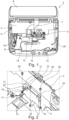
Fig. 1 ist eine Innenansicht einer erfindungsgemäßen medizinischen Fluidpumpe. -
Fig. 2 ist eine vergrößerte Darstellung eines Ausschnitts der Innenansicht der erfindungsgemäßen medizinischen Fluidpumpe mit einem drahtlosen Kommunikationsmodul in Form einer Kommunikationsplatine. -
Fig. 3 ist eine weitere vergrößerte Darstellung eines Ausschnitts der Innenansicht der erfindungsgemäßen medizinischen Fluidpumpe mit dem drahtlosen Kommunikationsmodul in Form der Kommunikationsplatine und einer ersten Antenne. -
Fig. 4 ist eine weitere vergrößerte Darstellung eines Ausschnitts der Innenansicht der erfindungsgemäßen medizinischen Fluidpumpe mit einer zweiten Antenne. -
Fig. 1 zeigt eine Innenansicht einer erfindungsgemäßen medizinischen Fluidpumpe 2 mit einem im Wesentlichen rechteckigen Gehäuse 4, Antriebskomponenten 5 und einer an einer Vorderseite des Gehäuses 4 der medizinischen Fluidpumpe 2 angebrachten Frontklappe 6, welche über ein Verbindungskabel 7 verbunden ist. Die medizinische Fluidpumpe 2 beinhaltet in dem Gehäuse 4 eine Platine / Mainboard 8, welche mit den wesentlichen Steuervorrichtungen der medizinischen Fluidpumpe 2, nämlich zumindest mit der Steuerungsvorrichtung eines Motors der medizinischen Fluidpumpe 2, bestückt ist, und ein drahtloses Kommunikationsmodul in Form einer Kommunikationsplatine 10. Die Kommunikationsplatine 10 ist im Wesentlichen senkrecht bzw. orthogonal zu der Platine 8 angeordnet. Anders ausgedrückt kontaktiert eine schmale Seite der Kommunikationsplatine 10 die Fläche der Platine 8. Die Kommunikationsplatine 10 ist im Wesentlichen mittig, bezogen auf eine Breitenrichtung des Gehäuses 4, angeordnet. Die Kommunikationsplatine 10 ist von einem metallischen Schirmkäfig 12 umschlossen. Die Kommunikationsplatine 10 ist mittels Kabel 14 mit Antennen 16, 26 verbunden. Die Antennen 16, 26 sind jeweils an Seitenwänden des Gehäuses 4 der medizinischen Fluidpumpe 2 angeordnet. Ein Abstand der Antennen 16, 26 zueinander beträgt dabei ein Vielfaches einer viertel bzw. einer halben Wellenlänge der Übertragungsfrequenz der Antennen 16, 26. -
Fig. 2 zeigt die Kommunikationsplatine 10 in dem Schirmkäfig 12 auf der Platine 8. Der Schirmkäfig 12 umschließt die Kommunikationsplatine 10 von sechs Seiten und verhindert, dass elektromagnetische Felder oder Strahlung die Funktion der Kommunikationsplatine 10 beeinflussen bzw. stören. Der Schirmkäfig 12 besteht aus Metallblech. Der Schirmkäfig 12 weist drei Füße 17 auf, die mit jeweils einem Durchgangsloch 18 versehen sind. Der Schirmkäfig 12 ist durch die Durchgangslöcher 18 mittels Schrauben 20 mit der Platine 8 verbunden. Durch das Vorsehen von drei Füßen 17 ist der Schirmkäfig 12 statisch bestimmt fixiert. Der Schirmkäfig 12 weist an der Platine 8 zugewandten Seite eine erste Anschlussöffnung (nicht dargestellt) auf. Durch die erste Anschlussöffnung ist die Kommunikationsplatine 10 mittels eines Platinensteckers mit der Platine 8 verbunden. Ferner weist der Schirmkäfig 12 eine zweite Anschlussöffnung 21 in einer orthogonal zu der Platine 8 orientierten Seitenfläche des Schirmkäfigs 12 auf. Durch die zweite Anschlussöffnung 21 sind die Kabel 14, welche die Kommunikationsplatine 10 mit den Antennen 16 verbinden, an der Kommunikationsplatine 10 angeschlossen. Der Schirmkäfig 12 weist ferner Ventilationsschlitze 22 auf, die einen Luftaustausch zwischen einem Inneren des Schirmkäfigs 12 und einem Innenraum des Gehäuses 4 der medizinischen Fluidpumpe verbessern, sodass ein Aufstauen von warmer Luft in dem Schirmkäfig 12 verhindert wird. In zwei in einem montierten Zustand von der Platine 8 abgewandten Eckabschnitten des Schirmkäfigs 12 sind Klemmelemente 25 ausgebildet, welche den Schirmkäfig 12 kraftschlüssig mit der Kommunikationsplatine 10 verbinden. In zwei in einem montierten Zustand der Platine 8 zugewandten Eckabschnitten des Schirmkäfigs 12 ist der Schirmkäfig 12 stoffschlüssig mit der Kommunikationsplatine 10 verbunden. -
Fig. 3 zeigt die Kommunikationsplatine 10 in dem Schirmkäfig 12 auf der Platine 8 sowie eine erste mittels Kabel 14 verbundene Antenne 16. Die erste Antenne 16 ist orthogonal zu der Platine 8 ausgerichtet und an einer Innenseite der Seitenwand des Gehäuses 4 der medizinischen Fluidpumpe 2 angebracht. In dem Gehäuse 4 ist zur Aufnahme der ersten Antenne 16 eine vertikale Antennenaufnahme 24 ausgebildet, welche die Antenne 16 formschlüssig aufnimmt. Die vertikale Antennenaufnahme 24 wird von zwei Schienen gebildet, die sich in einer Richtung orthogonal zu der Platine 8 erstrecken. Die Schienen ist stoffeinstückig mit dem Gehäuse 4 ausgebildet. -
Fig. 4 zeigt einen weiteren Ausschnitt des Inneren des Gehäuses 4 der medizinischen Fluidpumpe mit der Platine 8, den Kabeln 14 und einer zweiten Antenne 26, wobei die Kommunikationsplatine 10 zur besseren Übersichtlichkeit weggelassen wurde. Die zweite Antenne 26 ist parallel zu der Platine 8 ausgerichtet und damit um 90° versetzt zu der ersten Antenne 16 orientiert. Die zweite Antenne 26 ist an einer Innenseite der Seitenwand des Gehäuses 4 der medizinischen Fluidpumpe angebracht, die der ersten Antenne gegenüber liegt. In dem Gehäuse 4 ist zur Aufnahme der zweiten Antenne 26 eine horizontale Antennenaufnahme 28 ausgebildet, welche die Antenne 26 formschlüssig aufnimmt. Die horizontale Antennenaufnahme 28 wird von zwei Schienen gebildet, die sich in einer Richtung orthogonal zu der Platine 8 erstrecken. Die Schienen ist stoffeinstückig mit dem Gehäuse 4 ausgebildet. Sowohl die erste Antenne 16 als auch die zweite Antenne 26 sind mittels der Kabel 14 mit der Kommunikationsplatine 10 verbunden. Hierbei weisen das Kabel 14 zwischen der Kommunikationsplatine 10 und der ersten Antenne 16 und das Kabel 14 zwischen der Kommunikationsplatine und der zweiten Antenne 26 identische Lägen auf. Die Kabel 14 sind mittels Kabelklipsen 30 auf der Platine 8 fixiert. Mittels der Kabelklipse 30 sind die Antennen 16, 26 mit einem Massepotential der Platine 8 verbunden. -
- 2
- medizinische Fluidpumpe
- 4
- Gehäuse
- 6
- Frontklappe
- 8
- Platine
- 10
- Kommunikationsplatine
- 12
- (Schirm-)Käfig
- 14
- Kabel
- 16
- (erste) Antenne
- 17
- Fuß
- 18
- Durchgangsloch
- 20
- Schraube
- 21
- Anschlussöffnung
- 22
- Ventilationsschlitze
- 24
- vertikale Antennenaufnahme
- 25
- Klemmelement
- 26
- (zweite) Antenne
- 28
- horizontale Antennenaufnahme
- 30
- Kabelklips
Claims (10)
- Medizinische Fluidpumpe (2), vorzugsweise in Form einer Infusionspumpe oder Spritzenpumpe, mit einer Platine (8), welche mit den wesentlichen Steuervorrichtungen der medizinischen Fluidpumpe (2), nämlich zumindest mit der Steuerungsvorrichtung eines Motors der medizinischen Fluidpumpe (2), bestückt ist, und einem drahtlosen Kommunikationsmodul in Form einer Kommunikationsplatine (10), dadurch gekennzeichnet, dass die Kommunikationsplatine (10) im Wesentlichen senkrecht zu der Platine (8) angeordnet ist.
- Medizinische Fluidpumpe (2) nach Anspruch 1, dadurch gekennzeichnet, dass die Kommunikationsplatine (10) von einem metallischen oder metallische Elemente enthaltenden Käfig (12) umschlossen ist.
- Medizinische Fluidpumpe (2) nach Anspruch 2, dadurch gekennzeichnet, dass der Käfig (12) an einzelnen voneinander beabstandeten Punkten, insbesondere an vier Punkten, mit der Kommunikationsplatine (10) verbunden ist.
- Medizinische Fluidpumpe (2) nach Anspruch 3, dadurch gekennzeichnet, dass der Käfig (12) an zwei Punkten stoffschlüssig, insbesondere durch Löten, mit der Kommunikationsplatine (10) verbunden ist und an zwei Punkten kraftschlüssig, insbesondere durch Klemmen, mit der Kommunikationsplatine (10) verbunden ist.
- Medizinische Fluidpumpe (2) nach Anspruch 2 oder 3, dadurch gekennzeichnet, dass der Käfig (12) mit einem Massepotential der Platine (8) verbunden ist.
- Medizinische Fluidpumpe (2) nach einem der Ansprüche 1 bis 5, dadurch gekennzeichnet, dass die Kommunikationsplatine (10) mit mehreren, insbesondere zwei, Antennen (16, 26) verbunden ist.
- Medizinische Fluidpumpe (2) nach Anspruch 6, dadurch gekennzeichnet, dass die mehreren, insbesondere zwei, Antennen (16, 26) orthogonal zueinander angeordnet sind.
- Medizinische Fluidpumpe (2) nach Anspruch 6 oder 7, dadurch gekennzeichnet, dass die mehreren, insbesondere zwei, Antennen (16, 26) mittels Kabel (14) mit der Kommunikationsplatine (10) verbunden sind, wobei die Kabellängen der Kabel (14), welche die Kommunikationsplatine (10) mit den Antennen (16, 26) verbinden, identisch sind.
- Medizinische Fluidpumpe (2) nach einem der Ansprüche 6 bis 8, dadurch gekennzeichnet, dass die Antennen (16, 26) in einem Abstand zueinander angeordnet sind, der einem Vielfachen einer viertel, insbesondere einer halben, Wellenlänge der Sendefrequenz der Antennen (16, 26) entspricht.
- Medizinische Fluidpumpe (2) nach einem der Ansprüche 1 bis 9, dadurch gekennzeichnet, dass die Kommunikationsplatine (10) thermisch mit der Platine (8) gekoppelt ist.
Applications Claiming Priority (1)
| Application Number | Priority Date | Filing Date | Title |
|---|---|---|---|
| DE102021127113.4A DE102021127113A1 (de) | 2021-10-19 | 2021-10-19 | Drahtloses Kommunikationsmodul für medizinische Fluidpumpe |
Publications (1)
| Publication Number | Publication Date |
|---|---|
| EP4169549A1 true EP4169549A1 (de) | 2023-04-26 |
Family
ID=83692894
Family Applications (1)
| Application Number | Title | Priority Date | Filing Date |
|---|---|---|---|
| EP22201669.3A Pending EP4169549A1 (de) | 2021-10-19 | 2022-10-14 | Drahtloses kommunikationsmodul für medizinische fluidpumpe |
Country Status (4)
| Country | Link |
|---|---|
| US (1) | US20230120949A1 (de) |
| EP (1) | EP4169549A1 (de) |
| CN (1) | CN115996069A (de) |
| DE (1) | DE102021127113A1 (de) |
Families Citing this family (1)
| Publication number | Priority date | Publication date | Assignee | Title |
|---|---|---|---|---|
| DE102022108255A1 (de) * | 2022-04-06 | 2023-10-12 | Aesculap Ag | Elektrische medizinische Vorrichtung mit einer Antenne |
Citations (9)
| Publication number | Priority date | Publication date | Assignee | Title |
|---|---|---|---|---|
| US6388879B1 (en) * | 1994-03-17 | 2002-05-14 | Fujitsu Limited | Circuit board packaging structure |
| US20030050555A1 (en) * | 2001-04-30 | 2003-03-13 | Critchlow Richard G. | MR injector system with increased mobility and electromagnetic interference mitigation |
| US20040185897A1 (en) * | 2001-06-08 | 2004-09-23 | Torsten Ostervall | Portable radio communication device and an antenna arrangement for a portable radio communication device |
| US8213872B2 (en) * | 2007-12-19 | 2012-07-03 | Rambus Inc. | Technique for low-power operation of a wireless device |
| US8965287B2 (en) * | 2011-04-01 | 2015-02-24 | Tony Lam | Battery powered passive keyless entry system for premise entry |
| US20200203834A1 (en) * | 2017-09-30 | 2020-06-25 | Intel Corporation | Perpendicular end fire antennas |
| US20210170097A1 (en) * | 2008-09-15 | 2021-06-10 | Deka Products Limited Partnership | System and Methods for Fluid Delivery |
| DE202021103518U1 (de) * | 2021-07-01 | 2021-07-15 | B. Braun Melsungen Aktiengesellschaft | Pumpe mit hängend montierter Elektronik |
| KR102278616B1 (ko) * | 2021-01-11 | 2021-07-16 | 주식회사 이엠따블유 | 안테나 디바이스 및 이를 포함하는 차량 |
Family Cites Families (2)
| Publication number | Priority date | Publication date | Assignee | Title |
|---|---|---|---|---|
| DE102012208303B4 (de) * | 2012-05-16 | 2014-05-15 | Continental Automotive Gmbh | Antennenmodul mit Sende- und Empfangsantennenelement |
| US9408328B2 (en) * | 2012-06-07 | 2016-08-02 | Apple Inc. | Solid-state drive with passive heat transfer |
-
2021
- 2021-10-19 DE DE102021127113.4A patent/DE102021127113A1/de active Pending
-
2022
- 2022-10-14 EP EP22201669.3A patent/EP4169549A1/de active Pending
- 2022-10-18 US US17/968,053 patent/US20230120949A1/en active Pending
- 2022-10-18 CN CN202211275804.3A patent/CN115996069A/zh active Pending
Patent Citations (9)
| Publication number | Priority date | Publication date | Assignee | Title |
|---|---|---|---|---|
| US6388879B1 (en) * | 1994-03-17 | 2002-05-14 | Fujitsu Limited | Circuit board packaging structure |
| US20030050555A1 (en) * | 2001-04-30 | 2003-03-13 | Critchlow Richard G. | MR injector system with increased mobility and electromagnetic interference mitigation |
| US20040185897A1 (en) * | 2001-06-08 | 2004-09-23 | Torsten Ostervall | Portable radio communication device and an antenna arrangement for a portable radio communication device |
| US8213872B2 (en) * | 2007-12-19 | 2012-07-03 | Rambus Inc. | Technique for low-power operation of a wireless device |
| US20210170097A1 (en) * | 2008-09-15 | 2021-06-10 | Deka Products Limited Partnership | System and Methods for Fluid Delivery |
| US8965287B2 (en) * | 2011-04-01 | 2015-02-24 | Tony Lam | Battery powered passive keyless entry system for premise entry |
| US20200203834A1 (en) * | 2017-09-30 | 2020-06-25 | Intel Corporation | Perpendicular end fire antennas |
| KR102278616B1 (ko) * | 2021-01-11 | 2021-07-16 | 주식회사 이엠따블유 | 안테나 디바이스 및 이를 포함하는 차량 |
| DE202021103518U1 (de) * | 2021-07-01 | 2021-07-15 | B. Braun Melsungen Aktiengesellschaft | Pumpe mit hängend montierter Elektronik |
Also Published As
| Publication number | Publication date |
|---|---|
| DE102021127113A1 (de) | 2023-04-20 |
| US20230120949A1 (en) | 2023-04-20 |
| CN115996069A (zh) | 2023-04-21 |
Similar Documents
| Publication | Publication Date | Title |
|---|---|---|
| DE69122878T2 (de) | Erweiterungsfähige gekühlte gehäuse für computer-leiterplatten | |
| DE60010840T2 (de) | Drahtlose Übertragungseinrichtung für ein Elektroniksystem | |
| DE602004008013T2 (de) | Zirkularpolarisierte Schlitzantennenanordnung mit einfacher Miniaturisierungsmöglichkeit | |
| DE102022115688A1 (de) | Chip-package mit substratintegriertem wellenleiter und wellenleiterschnittstelle | |
| DE112016006983B4 (de) | Koaxialwellenleiter-Hohlwellenleiter-Übergangsschaltung | |
| EP3244483B1 (de) | Schirmgehäuse für hf-anwendungen | |
| EP4169549A1 (de) | Drahtloses kommunikationsmodul für medizinische fluidpumpe | |
| DE102016117105A1 (de) | Antenneeinrichtung | |
| DE102018103553A1 (de) | Elektronisches gerät | |
| DE112018007422T5 (de) | Wellenleiter-schlitzgruppenantenne | |
| DE4240755A1 (de) | Steuergerät, insbesondere für ein Kraftfahrzeug | |
| DE102012103217B3 (de) | Steuerungsgerät für ein Gebäudeinstallationssystem | |
| EP3607619A1 (de) | Steckverbindersystem | |
| DE60213307T2 (de) | Elektrischer Steckverbinder und Übertragungsleitung | |
| DE202016007979U1 (de) | Hauptplatinenanordnung | |
| WO2002063334A2 (de) | Integrierte schaltung für ein radargerät in hermetisch abgeschlossenem gehäuse mit einer aus einem blech-biegeteil geformten patch-antenne | |
| DE60221687T2 (de) | Mehrbreiten-sender/empfänger-host-board-system | |
| WO2017032639A1 (de) | Radarsensor für ein kraftfahrzeug, anordnung und kraftfahrzeug | |
| EP1370886B1 (de) | Antenne mit koplanarem speisenetzwerk zum senden und/oder empfangen von radarstrahlen | |
| EP3187031B1 (de) | Modulare baugruppe | |
| DE102013113877A1 (de) | Breitbandantenne | |
| DE60004444T2 (de) | Nichtreziproke Schaltungsanordnung und Kommunikationsgerät mit einer derartigen Schaltungsanordnung | |
| EP2954357B1 (de) | Gerätebuchse | |
| EP3447847B1 (de) | Verbinderelement und verbindersystem zum verbinden einer pcb-karte mit einem zentralrechner eines kraftfahrzeugs | |
| DE102021103546A1 (de) | Antennenvorrichtung |
Legal Events
| Date | Code | Title | Description |
|---|---|---|---|
| PUAI | Public reference made under article 153(3) epc to a published international application that has entered the european phase |
Free format text: ORIGINAL CODE: 0009012 |
|
| STAA | Information on the status of an ep patent application or granted ep patent |
Free format text: STATUS: THE APPLICATION HAS BEEN PUBLISHED |
|
| AK | Designated contracting states |
Kind code of ref document: A1 Designated state(s): AL AT BE BG CH CY CZ DE DK EE ES FI FR GB GR HR HU IE IS IT LI LT LU LV MC ME MK MT NL NO PL PT RO RS SE SI SK SM TR |
|
| STAA | Information on the status of an ep patent application or granted ep patent |
Free format text: STATUS: REQUEST FOR EXAMINATION WAS MADE |
|
| 17P | Request for examination filed |
Effective date: 20231026 |
|
| RBV | Designated contracting states (corrected) |
Designated state(s): AL AT BE BG CH CY CZ DE DK EE ES FI FR GB GR HR HU IE IS IT LI LT LU LV MC ME MK MT NL NO PL PT RO RS SE SI SK SM TR |
|
| STAA | Information on the status of an ep patent application or granted ep patent |
Free format text: STATUS: EXAMINATION IS IN PROGRESS |
|
| 17Q | First examination report despatched |
Effective date: 20260128 |