EP4167033B1 - Klang-absatz-einheit für einen schlagwerkmechanismus einer uhr - Google Patents
Klang-absatz-einheit für einen schlagwerkmechanismus einer uhr Download PDFInfo
- Publication number
- EP4167033B1 EP4167033B1 EP21203307.0A EP21203307A EP4167033B1 EP 4167033 B1 EP4167033 B1 EP 4167033B1 EP 21203307 A EP21203307 A EP 21203307A EP 4167033 B1 EP4167033 B1 EP 4167033B1
- Authority
- EP
- European Patent Office
- Prior art keywords
- heel
- gongs
- gong
- helix
- assembly
- Prior art date
- Legal status (The legal status is an assumption and is not a legal conclusion. Google has not performed a legal analysis and makes no representation as to the accuracy of the status listed.)
- Active
Links
Images

Classifications
-
- G—PHYSICS
- G04—HOROLOGY
- G04B—MECHANICALLY-DRIVEN CLOCKS OR WATCHES; MECHANICAL PARTS OF CLOCKS OR WATCHES IN GENERAL; TIME PIECES USING THE POSITION OF THE SUN, MOON OR STARS
- G04B21/00—Indicating the time by acoustic means
- G04B21/02—Regular striking mechanisms giving the full hour, half hour or quarter hour
- G04B21/08—Sounding bodies; Whistles; Musical apparatus
-
- G—PHYSICS
- G04—HOROLOGY
- G04B—MECHANICALLY-DRIVEN CLOCKS OR WATCHES; MECHANICAL PARTS OF CLOCKS OR WATCHES IN GENERAL; TIME PIECES USING THE POSITION OF THE SUN, MOON OR STARS
- G04B23/00—Arrangements producing acoustic signals at preselected times
- G04B23/02—Alarm clocks
- G04B23/028—Sounding bodies; boxes used as sounding cases; fixation on or in the case
-
- G—PHYSICS
- G04—HOROLOGY
- G04D—APPARATUS OR TOOLS SPECIALLY DESIGNED FOR MAKING OR MAINTAINING CLOCKS OR WATCHES
- G04D3/00—Watchmakers' or watch-repairers' machines or tools for working materials
- G04D3/0002—Watchmakers' or watch-repairers' machines or tools for working materials for mechanical working other than with a lathe
Definitions
- the present invention relates to a heel-gong assembly for a striking mechanism of a timepiece comprising a heel, a first gong comprising a first end secured to the heel and a second gong comprising a second end secured to the heel, said first and second gongs extending respectively from one side of the heel in opposite directions.
- the present invention also relates to a striking mechanism comprising such a heel-gong assembly as well as a timepiece comprising such a striking mechanism.
- the present invention also relates to a method of manufacturing such a heel-stamp assembly using a shaping fixture as well as said shaping fixture.
- a striking timepiece equipped with such a striking mechanism is, for example, a striking watch (such as a minute repeater, grande sonnerie, petite sonnerie, alarm clock) comprising, for example, two hammers and two gongs, generators of vibrations, arranged to be struck by their respective hammer when the striking mechanism is engaged to generate vibrations in order to produce a sound.
- a striking watch such as a minute repeater, grande sonnerie, petite sonnerie, alarm clock
- two hammers and two gongs, generators of vibrations arranged to be struck by their respective hammer when the striking mechanism is engaged to generate vibrations in order to produce a sound.
- Gongs are traditionally made of wires wound around the movement.
- the gongs are mounted securely on a heel or gong holder, which is attached to a part of the watch to transmit the gongs' vibrations to the wearer.
- gongs are configured to produce different sounds, one for striking the hours and the other for striking the minutes.
- the request EP 2 942 674 describes for example a heel-gong assembly comprising a heel or gong holder and two wound gongs.
- the example shown shows two gongs conventionally wound in the form of overlapping, parallel circles, positioned on the heel at different heights.
- the gongs can also describe a corkscrew shape around the watch movement.
- the gongs are wound in opposite directions and are not in contact with each other.
- the technical problem of the application EP 2 942 674 is to be able to easily produce a heel-gong set and change the gong, the proposed solution being to produce the gong and its gong holder at the same time as a mounting element in a watch case to form a single piece.
- gong heel rigidly attached to the movement or caseband.
- the gongs are fixed in the heel by extending in opposite directions, and by being positioned relative to each other with a sufficient difference in height so that they can wrap flat and parallel around the movement without touching when they are placed on top of each other.
- the patent CH 706 720 proposes, more particularly for cathedral gongs secured to a heel fixed on the plate of a movement, to use a heel-gong assembly in which the two gongs extend from the heel in the same plane to an area where, to avoid meeting, they change trajectory, one of the gongs changing radius and the other changing plane stamp. It is therefore proposed to use a flat spiral-shaped stamp and a helical-shaped stamp extending from the heel in the same plane.
- the two stamps are not parallel at all points, which leads to a risk of contact between the stamps.
- This requires, on the one hand, increasing the radius of the flat stamp and, on the other hand, providing, for the helical stamp, a sufficiently large pitch, in order to guarantee sufficient spacing between the stamps with the required safety features, hence an increase in the overall dimensions in diameter and in Z of the proposed heel-stamp assembly.
- the invention relates to a heel-gong assembly for a striking mechanism of a timepiece comprising a heel, a first gong comprising a first end secured to the heel and a second gong comprising a second end secured to the heel, said first and second gongs extending respectively from one side of the heel in opposite directions, the first gong being wound in a first helix and the second gong being wound in a second helix, said first and second helices being wound in opposite directions from the heel, the winding directions and the pitches of the first and second helices being chosen so as to have no contact between said first and second gongs.
- the first end of the first stamp and the second end of the second stamp are arranged in the same plane relative to the heel so as to be positioned on the heel at the same height.
- each of the timbres advantageously allows for a Z-shaped size, in thickness, that is to say the height of the movement and the amplification of the timbres is identical for the two notes.
- At least one of the first helix and the second helix, and preferably each of the first and second helixes, is a circular helix.
- This configuration advantageously allows the diameter to be kept to a minimum, and the gongs to be placed around the movement even in a restricted space.
- the first helix and the second helix have different radii, in order to give the timbres different notes.
- the first helix and the second helix have the same pitch in absolute value, in order to obtain timbres whose turns are in parallel planes.
- the first and second timbres each extend over less than one revolution.
- the present invention also relates to a striking mechanism of a timepiece comprising a heel-gong assembly as defined above, and first and second hammers intended to strike the first and second gongs respectively.
- the striking mechanism also comprises a lever linked to a support by an articulation along a single axis of rotation and secured to a membrane, said lever being secured to the heel of the heel-gong assembly.
- the present invention also relates to a timepiece comprising a striking mechanism as defined above.
- the present invention also relates to a shaping fixture for manufacturing the heel-stamp assembly by the method as defined above, said fixture comprising a lower element having an imprint corresponding to the helical shape of one of the stamps and to the shape of the lower part of the heel, an upper element having an imprint corresponding to the helical shape of the other of the stamps and to the shape of the upper part of the heel, the lower and upper elements being arranged to fit together, their respective imprints facing each other, and a separating plate arranged to be disposed between the lower element and the upper element and being intended to be inserted between the two stamps, said separating plate having a helical shape arranged so that its lower face is in contact with the stamp intended to be housed in the lower element and so that its upper face is in contact with the stamp intended to be housed in the upper element.
- the method and the installation according to the invention make it possible, for example, to produce a heel-gong assembly in which all the turns of the gongs are in perfectly parallel planes.
- a striking mechanism of a striking timepiece (such as a minute repeater, grand sonnerie, petite sonnerie, alarm clock) which comprises a first striking gong 1, a second striking gong 2, a first hammer 3 intended to strike the first gong 1 to produce a first note, to indicate the minutes for example, and a second hammer 4 intended to strike the second gong 2 to produce a second note, to indicate the hours for example.
- a striking timepiece such as a minute repeater, grand sonnerie, petite sonnerie, alarm clock
- the first and second stamps 1, 2 are preferably wires or rods of round section, metallic, made for example from unhardened steel, gold, platinum, or brass.
- the first stamp 1 comprises a first end 1a secured to a heel 6 and the second stamp 2 comprises a second end 2a secured to the heel 6.
- Said heel 6 comprises a lower part and an upper part defined by a face front, a back face and sides 6a, 6b.
- the first and second stamps 1, 2 extend respectively from a side 6a, 6b of the heel 6, in opposite directions, forming a heel-stamp assembly.
- the stamps 1, 2 are mounted on the heel 6 for example by embedding, locking with a screw, welding, brazing or even gluing.
- each side 6a, 6b of the heel 6 has an orifice 6c into which the stamp is inserted.
- the striking mechanism also comprises a lever 8 linked to a support 10 by an articulation 11 along a single axis of rotation, of the flexible pivot type, and secured to a membrane 12 in order to be able to move said membrane 12 when the lever 8 pivots. It is the movement of the membrane 12 moved by the lever 8 which will generate an amplified sound.
- a lever 8 linked to a support 10 by an articulation 11 along a single axis of rotation, of the flexible pivot type, and secured to a membrane 12 in order to be able to move said membrane 12 when the lever 8 pivots. It is the movement of the membrane 12 moved by the lever 8 which will generate an amplified sound.
- the lever 8 is also integral with the heel 6, mounted on said lever 8 by means of screws 14.
- the gongs 1, 2 are integral with the lever 8 and are not fixed, via the heel, to the frame of the watch.
- the heel-gong assembly of the invention can also be used in a traditional manner, by being fixed directly to the frame or another suitable element of the timepiece.
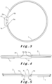
- the first stamp 1 is wound according to a first helix and the second stamp 2 is wound according to a second helix, said first and second helices being wound in opposite directions from the heel, that is to say going for each in an opposite direction from the heel towards its free end, the winding directions and the pitches of the first and second helices being chosen as necessary in order to have no possible contact between the first and second gongs, whether in the rest position or in vibration during operation of the chime.
- the pitches of the first and second helices are chosen to be necessary and sufficient so as to have no possible contact between the first and second gongs while having the smallest possible distance between the gongs so as to have a limited Z-dimension, depending on the thickness of the movement.
- the winding of the gongs in helices of opposite directions advantageously makes it possible to avoid any risk of contact between the gongs 1, 2 without having to provide additional safety.
- the first end 1a of the first stamp 1 and the second end 2a of the second stamp 2 are arranged in the same embedding plane P relative to the longitudinal plane of the heel 6 so as to be positioned on the sides 6a, 6b of said heel 6 at the same height.
- the first end 1a of the first stamp 1 and the second end 2a of the second stamp 2 are arranged symmetrically relative to the axial plane of the heel 6 so as to be opposite each other on each side of the heel 6.
- stamp 1 is "descending”, being wound in a counterclockwise helix starting from the right side of heel 6 as seen from its rear face
- stamp 2 is "ascending”, being wound in a clockwise helix starting from the left side of heel 6 as seen from its rear face.
- At least one of the first helix and the second helix is a circular helix. More preferably, each of the first and second helixes is a circular helix, i.e., of constant winding radius.
- a constant radius means a variation in the radius of less than 15%, preferably less than 10% and more preferably less than 5%, related to the manufacture of the gong. This means that the winding radius of the gong is not intentionally modified to be increased or decreased.
- the first and second stamps 1, 2 each extend over less than one revolution.
- the configuration of the lever and its support then being adapted to allow the passage of the gongs.
- the gongs will be wound in helices of opposite directions and of increasing winding radius.
- the first helix and the second helix have different winding radii, so that their lengths are different to produce different notes. This allows the advantageous use of timbres 1, 2 of identical radius.
- winding radii of the gongs are preferably chosen to go around the movement.
- the first helix and the second helix have the same pitch (in absolute value), so that the gongs 1 and 2 have turns which are always wound parallel to each other.
- the pitch of the helices is chosen so that the gongs 1, 2 are sufficiently spaced from each other so as not to touch each other.
- the first and second gongs 1, 2 each extend over less than one turn and are wound in a cylindrical helix of the same pitch.
- the first gong 1 is wound according to a first cylindrical helix which has the smallest winding radius to generate the minute note, and the pitch of the first and second helices is identical.
- the diameter size is equal to the winding diameter of the second cylindrical helix which has the largest winding radius, here gong 2, so that the diameter size of gongs 1, 2 is limited.
- the two gongs 1, 2 wound in helices in opposite directions and with an identical pitch remain constantly parallel to each other, while vibrating freely and independently.
- the helically wound gongs allow each of the gongs to change plane immediately after their embedding so that one of the gongs 1 has its free end lower than the embedding plane P and the other gong 2 has its free end higher than the embedding plane P, as shown in Figure 5 .
- the parallel space which is constantly maintained between the stamps 1, 2 from their point of embedding allows there to be no contact between said stamps, keeping the winding radii constant, even when the stamps are almost one turn and that their free end returns close to the point of embedding of the other gong, bypassing the movement, as shown in the Figure 5 .
- the heel-stamp assembly according to the invention preferably requires the use of a specific setting making it possible to give the stamps the desired helical shape, in particular during the tempering operation.
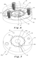
- the installation 20 comprises a lower element 20a and an upper element 20b, of generally cylindrical shape, and having a central opening 22, in particular to promote the circulation of heat during heat treatment.
- the upper face 24 of the lower element 20a is of helical shape corresponding substantially to the helical shape here of the first descending stamp 1.
- the upper face 24 has an imprint 26 concentric with the central opening 22, and comprising a groove 26a corresponding substantially to the helical shape of the first stamp 1 and a hollow 26b corresponding substantially to the shape of the lower part of the heel 6.
- the groove 26a is interspersed with through holes 28 to promote the circulation of heat during a heat treatment.
- the depth of the groove 26a is substantially equal to the diameter of the stamp 1 intended to be housed therein so that said stamp 1 will arrive flush with the groove 26a.
- the upper face 24 of the lower element 20a being of helical shape, it comprises a shoulder 29 extending radially at the level of the hollow 26b.
- the lower element 20a also has holes 30 for being assembled to the upper element 20b by means of screws 32.
- the upper element 20b is generally symmetrical to the lower element 20a with respect to a plane perpendicular to the axis of the installation 20.
- the lower face of the upper element 20b is of helical shape corresponding substantially to the helical shape of the second rising stamp 2.
- the lower face of the upper element 20b has an imprint concentric with the central opening, and comprising a groove corresponding substantially to the helical shape of the second rising stamp 2 and a hollow corresponding substantially to the shape of the upper part of the heel 6.
- the groove is interspersed with through holes to promote the circulation of heat during heat treatment.
- the depth of the groove is substantially equal to the diameter of the stamp 2 intended to be housed there so that said stamp 2 will arrive flush with the groove.
- the lower face of the upper element 20b being of helical shape, it comprises a shoulder 34 extending radially at the level of the hollow.
- the lower 20a and upper 20b elements are arranged to fit together, in particular at the level of the complementary shoulders 29 and 34, to form the mounting 20, their respective imprints being opposite each other, as well as the orifices 28 and the central opening 22.
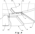
- the installation 20 also comprises a separation plate 36 arranged to be placed between the lower element 20a and the upper element 20b by being inserted between the two stamps 1, 2.
- Said separation plate 36 is a flexible plate having a helical shape arranged so that its lower face 36a is in contact with the first stamp 1 housed in the groove 26a of the lower element 20a and so that its upper face 36b is in contact with the second stamp 2 housed in the groove of the upper element 20b, as shown in figure 8 .
- the separating plate 36 is guided and held by means of pins 38 provided on the lower element 20a.
- the separation plate 36 also has cutouts to bypass the heel 6, the screws 32 and the pins 38.
- the thickness of the separation plate 36 is just less than the pitch of the helices so that it can fit perfectly into the space between the turn of the first stamp 1 and the turn of the second stamp 2.
- the lower 20a and upper 20b elements of the installation 20 can be made of brass for example.
- the resulting heel-stamp assembly can then undergo another step, such as a finishing treatment, such as polishing, in order to give it its final appearance.
- a finishing treatment such as polishing
- the various elements of the shaping unit 20 (impressions and separation plate) provided for guiding and holding the stamps during treatment thermal, in particular income, allow, thanks to their helical shapes, to maintain a perfectly parallel space between each of the stamps 1, 2.
- the separating plate 36 fitting perfectly between the turn of the first stamp 1 and the turn of the second stamp 2, its lower 36a and upper 36b faces are in contact with the stamp 1 and the stamp 2 respectively, over their entire length.
- the separating plate 36 prevents the stamps 1, 2 from touching each other and guides them in the shaping position 20 in a constant and progressive manner to give them their helical shapes in opposite directions, in cooperation with the corresponding impressions of the lower 20a and upper 20b elements.
- a heel-stamp assembly is obtained in which the stamps have the desired shapes, that is to say wound in helices in opposite directions and allowing no contact, one of the stamps being rising and the other falling, and preferably parallel.
Landscapes
- Physics & Mathematics (AREA)
- General Physics & Mathematics (AREA)
- Acoustics & Sound (AREA)
- Engineering & Computer Science (AREA)
- Multimedia (AREA)
- Stringed Musical Instruments (AREA)
- Heat Treatment Of Articles (AREA)
Claims (10)
- Klötzchen-Tonfeder-Einheit für einen Schlagwerkmechanismus einer Uhr, umfassend einen Klötzchen (6), eine erste Tonfeder (1) mit einem ersten, mit dem Klötzchen (6) fest verbundenen Ende (1a), und eine zweite Tonfeder (2) mit einem zweiten, mit dem Klötzchen (6) fest verbundenen Ende (2a), wobei die besagten erste und zweite Tonfeder (1, 2) jeweils von einer Seite (6a, 6b) des Klötzchens (6) in entgegengesetzte Richtungen abgehen, wobei die erste Tonfeder (1) entsprechend einer ersten Helix und die zweite Tonfeder (2) entsprechend einer zweiten Helix aufgerollt ist, wobei die besagten erste und zweite Helix vom Klötzchen (6) abgehend in entgegengesetzten Richtungen aufgerollt sind, wobei die Aufrollrichtungen und die Steigungen der ersten und zweiten Helix so gewählt sind, dass es keine Berührung zwischen der ersten und zweiten Tonfeder (1, 2) gibt, dadurch gekennzeichnet, dass das erste Ende (1a) der ersten Tonfeder (1) und das zweite Ende (2a) der zweiten Tonfeder (2) in einer gleichen Ebene (P) in Bezug auf den Klötzchen (6) so angeordnet sind, um in gleicher Höhe auf dem Klötzchen (6) positioniert zu sein.
- Klötzchen-Tonfeder-Einheit nach Anspruch 1, dadurch gekennzeichnet, dass mindestens eine der ersten Helix und der zweiten Helix, und vorzugsweise jede der ersten und zweiten Helix, eine kreisförmige Helix ist.
- Einheit nach einem der vorstehenden Ansprüche, dadurch gekennzeichnet, dass die erste Helix und die zweite Helix unterschiedliche Radien haben.
- Einheit nach einem der vorstehenden Ansprüche, dadurch gekennzeichnet, dass die erste Helix und die zweite Helix dieselbe Steigung als Absolutwert haben.
- Einheit nach einem der vorstehenden Ansprüche, dadurch gekennzeichnet, dass die erste und zweite Tonfeder (1, 2) sich jede über weniger als eine Umdrehung erstrecken.
- Schlagwerkmechanismus einer Uhr, umfassend eine Klötzchen-Tonfeder-Einheit nach einem der vorstehenden Ansprüche und einen ersten und zweiten Hammer (3, 4), die dazu bestimmt sind, jeweils die erste und zweite Tonfeder (1, 2) anzuschlagen.
- Schlagwerkmechanismus nach Anspruch 6, dadurch gekennzeichnet, dass er einen Hebel (8) umfasst, der durch ein Gelenk (11) entlang einer einzigen Drehachse mit einem Träger (10) verbunden und mit einer Membran (12) fest verbunden ist, wobei der besagte Hebel (8) mit dem Klötzchen (6) der Klötzchen-Tonfeder-Einheit fest verbunden ist.
- Uhr mit einem Schlagwerkmechanismus nach einem der Ansprüche 6 und 7.
- Verfahren zur Herstellung einer Klötzchen-Tonfeder-Einheit nach einem der Ansprüche 1 bis 5, das die folgenden Schritte umfasst:- Befestigen des ersten Endes (1a) der ersten Tonfeder (1) und des zweiten Endes (2a) der zweiten Tonfeder (2) jeweils an einer ersten (6a) und zweiten (6b) Seite des Klötzchens (6), wobei das erste Ende (1a) der ersten Tonfeder (1) und das zweite Ende (2a) der zweiten Tonfeder (2) in einer gleichen Ebene (P) in Bezug auf den Klötzchen (6) so angeordnet sind, um in gleicher Höhe auf dem Klötzchen (6) positioniert zu sein;- Anordnen der Klötzchen-Tonfeder-Einheit in einem Untersatz zur Formung (20), der ein unteres Element (20a) mit einem Abdruck entsprechend der Schraubenform einer der Tonfedern (1, 2) und der Form des unteren Teils des Klötzchens (6), ein oberes Element (20b) mit einem Abdruck entsprechend der Schraubenform der anderen Tonfeder (1, 2) und der Form des oberen Teils des Klötzchens (6) umfasst, wobei das untere (20a) und das obere (20b) Element so ausgelegt sind, dass sie ineinander passen, wobei ihre jeweiligen Abdrücke einander gegenüberliegen, und eine Trennplatte (36) umfasst, die zwischen dem unteren Element (20a) und dem oberen Element (20b) angeordnet ist, indem sie sich zwischen die beiden Tonfedern (1, 2) einfügt, wobei die besagte Trennplatte (36) eine Schraubenform aufweist, die so ausgelegt ist, dass ihre Unterseite die im unteren Element (20a) aufgenommene Tonfeder berührt und ihre Oberseite die im oberen Element (20b) aufgenommene Tonfeder berührt;- Durchführen von mindestens einer thermischen Behandlung der in ihrem Untersatz zur Formung (20) eingefügten Klötzchen-Tonfeder-Einheit;- Herausnehmen der Klötzchen-Tonfeder-Einheit aus ihrem Untersatz zur Formung (20).
- Untersatz zur Formung (20) für die Herstellung der Klötzchen-Tonfeder-Einheit durch das Verfahren nach Anspruch 9, dadurch gekennzeichnet, dass der besagte Untersatz zur Formung (20) ein unteres Element (20a) mit einem Abdruck entsprechend der Schraubenform einer der Tonfedern (1, 2) und der Form des unteren Teils des Klötzchens (6), ein oberes Element (20b) mit einem Abdruck entsprechend der Schraubenform der anderen Tonfeder (1, 2) und der Form des oberen Teils des Klötzchens (6) umfasst, wobei das untere (20a) und das obere (20b) Element so ausgelegt sind, dass sie ineinander passen, wobei ihre jeweiligen Abdrücke einander gegenüberliegen, und eine Trennplatte (36) umfasst, die ausgelegt ist, um zwischen dem unteren Element (20a) und dem oberen Element (20b) angeordnet zu sein, indem sie dazu bestimmt ist, sich zwischen die beiden Tonfedern (1, 2) einzufügen, wobei die besagte Trennplatte (36) eine Schraubenform aufweist, die so ausgelegt ist, dass ihre Unterseite die zur Aufnahme im unteren Element (20a) bestimmte Tonfeder berührt, und ihre Oberseite die zur Aufnahme im oberen Element (20b) bestimmte Tonfeder berührt.
Priority Applications (1)
| Application Number | Priority Date | Filing Date | Title |
|---|---|---|---|
| EP21203307.0A EP4167033B1 (de) | 2021-10-18 | 2021-10-18 | Klang-absatz-einheit für einen schlagwerkmechanismus einer uhr |
Applications Claiming Priority (1)
| Application Number | Priority Date | Filing Date | Title |
|---|---|---|---|
| EP21203307.0A EP4167033B1 (de) | 2021-10-18 | 2021-10-18 | Klang-absatz-einheit für einen schlagwerkmechanismus einer uhr |
Publications (2)
| Publication Number | Publication Date |
|---|---|
| EP4167033A1 EP4167033A1 (de) | 2023-04-19 |
| EP4167033B1 true EP4167033B1 (de) | 2025-06-18 |
Family
ID=78463396
Family Applications (1)
| Application Number | Title | Priority Date | Filing Date |
|---|---|---|---|
| EP21203307.0A Active EP4167033B1 (de) | 2021-10-18 | 2021-10-18 | Klang-absatz-einheit für einen schlagwerkmechanismus einer uhr |
Country Status (1)
| Country | Link |
|---|---|
| EP (1) | EP4167033B1 (de) |
Family Cites Families (5)
| Publication number | Priority date | Publication date | Assignee | Title |
|---|---|---|---|---|
| ATE518169T1 (de) * | 2006-10-12 | 2011-08-15 | Christophe Claret Sa | Glockenisolator |
| CH706720B1 (fr) | 2012-07-11 | 2016-09-30 | Richemont Int Sa | Ensemble talon et timbres pour un mécanisme de sonnerie d'une pièce d'horlogerie. |
| EP2942674B1 (de) * | 2014-05-06 | 2018-10-03 | Blancpain SA. | Einheit zur Erzeugung eines Uhrschlags eines Schlagwerkmechanismus |
| CH715470A1 (fr) * | 2018-10-25 | 2020-04-30 | Mft Et Fabrique De Montres Et Chronometres Ulysse Nardin Le Locle S A | Montre à sonnerie. |
| EP3812844B1 (de) | 2019-10-25 | 2023-09-06 | Patek Philippe SA Genève | Uhr, die eine schwingungsverstärkungsvorrichtung umfasst |
-
2021
- 2021-10-18 EP EP21203307.0A patent/EP4167033B1/de active Active
Also Published As
| Publication number | Publication date |
|---|---|
| EP4167033A1 (de) | 2023-04-19 |
Similar Documents
| Publication | Publication Date | Title |
|---|---|---|
| EP2145237B1 (de) | Uhrenkomponente und verfahren zu ihrer herstellung | |
| CN101978326B (zh) | 一体式调节元件及其制造方法 | |
| EP2104006B1 (de) | Monoblock-Doppelspirale und ihr Herstellungsverfahren | |
| EP2175328A2 (de) | Spiralfeder der Resonatorunruh und Fabrikationsmethode | |
| EP3181940B2 (de) | Herstellungsverfahren einer spiralfeder mit einer vorbestimmten steifigkeit durch lokalisierte wegnahme von material | |
| EP3088969B1 (de) | Thermocompensierte spiralfeder und verfahren zu deren herstellung | |
| EP3211488B1 (de) | Atypische glocke, armbanduhr mit schlagwerkmechanismus, der diese glocke umfasst, und herstellungsverfahren dieser glocke | |
| EP2207069A2 (de) | Stütze für Tonfedern in Uhren | |
| EP2520984A1 (de) | Federhaus umfassend zusätzlichen elastischen Mitteln zur Energieakkumulation | |
| EP2196869A1 (de) | Uhrengehäuse mit Schlagwerkvorrichtung | |
| EP2104007A1 (de) | Monoblockspirale aus Material auf Siliziumbasis und ihr Herstellungsverfahren | |
| WO2006095244A2 (fr) | Dispositif de fixation d’au moins un timbre de sonnerie dans une piece d’horlogerie et procede de fixation d’au moins un timbre de sonnerie dans une piece d’horlogerie | |
| EP2690506A1 (de) | Antischwingungsspirale für Uhr | |
| EP4167033B1 (de) | Klang-absatz-einheit für einen schlagwerkmechanismus einer uhr | |
| EP2138912B1 (de) | Spiralfeder für Uhrwerk mit konzentrischer Entwicklung | |
| EP1654597A1 (de) | Unruh mit thermokompensation | |
| EP4310605B1 (de) | Uhrwerk mit einem schlagwerk, das mit einer flexiblen führung ausgestattet ist | |
| EP3537228B1 (de) | Vorrichtung zur regulierung der schwingungsfrequenz der klangfarbe eines schlagwerkmechanismus | |
| EP4310604B1 (de) | Uhrwerk mit einem schlagwerk, das mit einer flexiblen führung ausgestattet ist | |
| EP2488921B1 (de) | Energiequelle für ein schlagwerk und uhr mit einer derartigen energiequelle | |
| CH695395A5 (fr) | Spiral de résonateur balancier-spiral. | |
| EP4432020A1 (de) | Uhrwerk | |
| CH717357B1 (fr) | Spiral horloger en verre ou en céramique, à géométrie complexe. | |
| CH706653A2 (fr) | Ressort-moteur pour une pièce d'horlogerie. | |
| EP4113219B1 (de) | Verfahren zur frequenzabstimmung einer plattengruppe einer armbanduhr und armbanduhr mit dieser abgestimmten plattengruppe |
Legal Events
| Date | Code | Title | Description |
|---|---|---|---|
| PUAI | Public reference made under article 153(3) epc to a published international application that has entered the european phase |
Free format text: ORIGINAL CODE: 0009012 |
|
| STAA | Information on the status of an ep patent application or granted ep patent |
Free format text: STATUS: THE APPLICATION HAS BEEN PUBLISHED |
|
| AK | Designated contracting states |
Kind code of ref document: A1 Designated state(s): AL AT BE BG CH CY CZ DE DK EE ES FI FR GB GR HR HU IE IS IT LI LT LU LV MC MK MT NL NO PL PT RO RS SE SI SK SM TR |
|
| P01 | Opt-out of the competence of the unified patent court (upc) registered |
Effective date: 20230521 |
|
| STAA | Information on the status of an ep patent application or granted ep patent |
Free format text: STATUS: REQUEST FOR EXAMINATION WAS MADE |
|
| 17P | Request for examination filed |
Effective date: 20231018 |
|
| RBV | Designated contracting states (corrected) |
Designated state(s): AL AT BE BG CH CY CZ DE DK EE ES FI FR GB GR HR HU IE IS IT LI LT LU LV MC MK MT NL NO PL PT RO RS SE SI SK SM TR |
|
| GRAP | Despatch of communication of intention to grant a patent |
Free format text: ORIGINAL CODE: EPIDOSNIGR1 |
|
| STAA | Information on the status of an ep patent application or granted ep patent |
Free format text: STATUS: GRANT OF PATENT IS INTENDED |
|
| INTG | Intention to grant announced |
Effective date: 20250122 |
|
| GRAS | Grant fee paid |
Free format text: ORIGINAL CODE: EPIDOSNIGR3 |
|
| GRAA | (expected) grant |
Free format text: ORIGINAL CODE: 0009210 |
|
| STAA | Information on the status of an ep patent application or granted ep patent |
Free format text: STATUS: THE PATENT HAS BEEN GRANTED |
|
| AK | Designated contracting states |
Kind code of ref document: B1 Designated state(s): AL AT BE BG CH CY CZ DE DK EE ES FI FR GB GR HR HU IE IS IT LI LT LU LV MC MK MT NL NO PL PT RO RS SE SI SK SM TR |
|
| REG | Reference to a national code |
Ref country code: GB Ref legal event code: FG4D Free format text: NOT ENGLISH |
|
| REG | Reference to a national code |
Ref country code: CH Ref legal event code: EP |
|
| REG | Reference to a national code |
Ref country code: DE Ref legal event code: R096 Ref document number: 602021032380 Country of ref document: DE |
|
| REG | Reference to a national code |
Ref country code: CH Ref legal event code: EP |
|
| REG | Reference to a national code |
Ref country code: IE Ref legal event code: FG4D Free format text: LANGUAGE OF EP DOCUMENT: FRENCH |
|
| PG25 | Lapsed in a contracting state [announced via postgrant information from national office to epo] |
Ref country code: FI Free format text: LAPSE BECAUSE OF FAILURE TO SUBMIT A TRANSLATION OF THE DESCRIPTION OR TO PAY THE FEE WITHIN THE PRESCRIBED TIME-LIMIT Effective date: 20250618 |
|
| REG | Reference to a national code |
Ref country code: LT Ref legal event code: MG9D |
|
| PG25 | Lapsed in a contracting state [announced via postgrant information from national office to epo] |
Ref country code: GR Free format text: LAPSE BECAUSE OF FAILURE TO SUBMIT A TRANSLATION OF THE DESCRIPTION OR TO PAY THE FEE WITHIN THE PRESCRIBED TIME-LIMIT Effective date: 20250919 Ref country code: NO Free format text: LAPSE BECAUSE OF FAILURE TO SUBMIT A TRANSLATION OF THE DESCRIPTION OR TO PAY THE FEE WITHIN THE PRESCRIBED TIME-LIMIT Effective date: 20250918 |
|
| PG25 | Lapsed in a contracting state [announced via postgrant information from national office to epo] |
Ref country code: BG Free format text: LAPSE BECAUSE OF FAILURE TO SUBMIT A TRANSLATION OF THE DESCRIPTION OR TO PAY THE FEE WITHIN THE PRESCRIBED TIME-LIMIT Effective date: 20250618 |
|
| PGFP | Annual fee paid to national office [announced via postgrant information from national office to epo] |
Ref country code: GB Payment date: 20250828 Year of fee payment: 5 |
|
| PG25 | Lapsed in a contracting state [announced via postgrant information from national office to epo] |
Ref country code: HR Free format text: LAPSE BECAUSE OF FAILURE TO SUBMIT A TRANSLATION OF THE DESCRIPTION OR TO PAY THE FEE WITHIN THE PRESCRIBED TIME-LIMIT Effective date: 20250618 |
|
| PG25 | Lapsed in a contracting state [announced via postgrant information from national office to epo] |
Ref country code: RS Free format text: LAPSE BECAUSE OF FAILURE TO SUBMIT A TRANSLATION OF THE DESCRIPTION OR TO PAY THE FEE WITHIN THE PRESCRIBED TIME-LIMIT Effective date: 20250918 |
|
| REG | Reference to a national code |
Ref country code: NL Ref legal event code: MP Effective date: 20250618 |
|
| PG25 | Lapsed in a contracting state [announced via postgrant information from national office to epo] |
Ref country code: LV Free format text: LAPSE BECAUSE OF FAILURE TO SUBMIT A TRANSLATION OF THE DESCRIPTION OR TO PAY THE FEE WITHIN THE PRESCRIBED TIME-LIMIT Effective date: 20250618 |
|
| REG | Reference to a national code |
Ref country code: CH Ref legal event code: U11 Free format text: ST27 STATUS EVENT CODE: U-0-0-U10-U11 (AS PROVIDED BY THE NATIONAL OFFICE) Effective date: 20251101 |
|
| PG25 | Lapsed in a contracting state [announced via postgrant information from national office to epo] |
Ref country code: NL Free format text: LAPSE BECAUSE OF FAILURE TO SUBMIT A TRANSLATION OF THE DESCRIPTION OR TO PAY THE FEE WITHIN THE PRESCRIBED TIME-LIMIT Effective date: 20250618 |
|
| PG25 | Lapsed in a contracting state [announced via postgrant information from national office to epo] |
Ref country code: PT Free format text: LAPSE BECAUSE OF FAILURE TO SUBMIT A TRANSLATION OF THE DESCRIPTION OR TO PAY THE FEE WITHIN THE PRESCRIBED TIME-LIMIT Effective date: 20251020 |
|
| REG | Reference to a national code |
Ref country code: AT Ref legal event code: MK05 Ref document number: 1804756 Country of ref document: AT Kind code of ref document: T Effective date: 20250618 |
|
| PG25 | Lapsed in a contracting state [announced via postgrant information from national office to epo] |
Ref country code: IS Free format text: LAPSE BECAUSE OF FAILURE TO SUBMIT A TRANSLATION OF THE DESCRIPTION OR TO PAY THE FEE WITHIN THE PRESCRIBED TIME-LIMIT Effective date: 20251018 |
|
| PGFP | Annual fee paid to national office [announced via postgrant information from national office to epo] |
Ref country code: DE Payment date: 20250827 Year of fee payment: 5 |
|
| PG25 | Lapsed in a contracting state [announced via postgrant information from national office to epo] |
Ref country code: AT Free format text: LAPSE BECAUSE OF FAILURE TO SUBMIT A TRANSLATION OF THE DESCRIPTION OR TO PAY THE FEE WITHIN THE PRESCRIBED TIME-LIMIT Effective date: 20250618 Ref country code: SM Free format text: LAPSE BECAUSE OF FAILURE TO SUBMIT A TRANSLATION OF THE DESCRIPTION OR TO PAY THE FEE WITHIN THE PRESCRIBED TIME-LIMIT Effective date: 20250618 |
|
| PGFP | Annual fee paid to national office [announced via postgrant information from national office to epo] |
Ref country code: CH Payment date: 20251101 Year of fee payment: 5 |
|
| PG25 | Lapsed in a contracting state [announced via postgrant information from national office to epo] |
Ref country code: CZ Free format text: LAPSE BECAUSE OF FAILURE TO SUBMIT A TRANSLATION OF THE DESCRIPTION OR TO PAY THE FEE WITHIN THE PRESCRIBED TIME-LIMIT Effective date: 20250618 |
|
| PG25 | Lapsed in a contracting state [announced via postgrant information from national office to epo] |
Ref country code: PL Free format text: LAPSE BECAUSE OF FAILURE TO SUBMIT A TRANSLATION OF THE DESCRIPTION OR TO PAY THE FEE WITHIN THE PRESCRIBED TIME-LIMIT Effective date: 20250618 |
|
| PG25 | Lapsed in a contracting state [announced via postgrant information from national office to epo] |
Ref country code: EE Free format text: LAPSE BECAUSE OF FAILURE TO SUBMIT A TRANSLATION OF THE DESCRIPTION OR TO PAY THE FEE WITHIN THE PRESCRIBED TIME-LIMIT Effective date: 20250618 |
|
| PG25 | Lapsed in a contracting state [announced via postgrant information from national office to epo] |
Ref country code: SK Free format text: LAPSE BECAUSE OF FAILURE TO SUBMIT A TRANSLATION OF THE DESCRIPTION OR TO PAY THE FEE WITHIN THE PRESCRIBED TIME-LIMIT Effective date: 20250618 |
|
| PG25 | Lapsed in a contracting state [announced via postgrant information from national office to epo] |
Ref country code: ES Free format text: LAPSE BECAUSE OF FAILURE TO SUBMIT A TRANSLATION OF THE DESCRIPTION OR TO PAY THE FEE WITHIN THE PRESCRIBED TIME-LIMIT Effective date: 20250618 |
|
| PG25 | Lapsed in a contracting state [announced via postgrant information from national office to epo] |
Ref country code: RO Free format text: LAPSE BECAUSE OF FAILURE TO SUBMIT A TRANSLATION OF THE DESCRIPTION OR TO PAY THE FEE WITHIN THE PRESCRIBED TIME-LIMIT Effective date: 20250618 |
|
| PG25 | Lapsed in a contracting state [announced via postgrant information from national office to epo] |
Ref country code: DK Free format text: LAPSE BECAUSE OF FAILURE TO SUBMIT A TRANSLATION OF THE DESCRIPTION OR TO PAY THE FEE WITHIN THE PRESCRIBED TIME-LIMIT Effective date: 20250618 |
|
| PG25 | Lapsed in a contracting state [announced via postgrant information from national office to epo] |
Ref country code: IT Free format text: LAPSE BECAUSE OF FAILURE TO SUBMIT A TRANSLATION OF THE DESCRIPTION OR TO PAY THE FEE WITHIN THE PRESCRIBED TIME-LIMIT Effective date: 20250618 |
|
| PLBE | No opposition filed within time limit |
Free format text: ORIGINAL CODE: 0009261 |
|
| STAA | Information on the status of an ep patent application or granted ep patent |
Free format text: STATUS: NO OPPOSITION FILED WITHIN TIME LIMIT |