EP4166894B1 - Feuerwaffe mit einer eine verstelleinrichtung aufweisenden abzugsgruppe - Google Patents
Feuerwaffe mit einer eine verstelleinrichtung aufweisenden abzugsgruppe Download PDFInfo
- Publication number
- EP4166894B1 EP4166894B1 EP22199775.2A EP22199775A EP4166894B1 EP 4166894 B1 EP4166894 B1 EP 4166894B1 EP 22199775 A EP22199775 A EP 22199775A EP 4166894 B1 EP4166894 B1 EP 4166894B1
- Authority
- EP
- European Patent Office
- Prior art keywords
- trigger
- firearm
- adjustment
- command member
- rod
- Prior art date
- Legal status (The legal status is an assumption and is not a legal conclusion. Google has not performed a legal analysis and makes no representation as to the accuracy of the status listed.)
- Active
Links
Images


Classifications
-
- F—MECHANICAL ENGINEERING; LIGHTING; HEATING; WEAPONS; BLASTING
- F41—WEAPONS
- F41A—FUNCTIONAL FEATURES OR DETAILS COMMON TO BOTH SMALLARMS AND ORDNANCE, e.g. CANNONS; MOUNTINGS FOR SMALLARMS OR ORDNANCE
- F41A19/00—Firing or trigger mechanisms; Cocking mechanisms
- F41A19/06—Mechanical firing mechanisms, e.g. counterrecoil firing, recoil actuated firing mechanisms
- F41A19/16—Adjustable firing mechanisms; Trigger mechanisms with adjustable trigger pull
-
- F—MECHANICAL ENGINEERING; LIGHTING; HEATING; WEAPONS; BLASTING
- F41—WEAPONS
- F41A—FUNCTIONAL FEATURES OR DETAILS COMMON TO BOTH SMALLARMS AND ORDNANCE, e.g. CANNONS; MOUNTINGS FOR SMALLARMS OR ORDNANCE
- F41A19/00—Firing or trigger mechanisms; Cocking mechanisms
- F41A19/06—Mechanical firing mechanisms, e.g. counterrecoil firing, recoil actuated firing mechanisms
- F41A19/15—Modular firing mechanism units
-
- F—MECHANICAL ENGINEERING; LIGHTING; HEATING; WEAPONS; BLASTING
- F41—WEAPONS
- F41A—FUNCTIONAL FEATURES OR DETAILS COMMON TO BOTH SMALLARMS AND ORDNANCE, e.g. CANNONS; MOUNTINGS FOR SMALLARMS OR ORDNANCE
- F41A19/00—Firing or trigger mechanisms; Cocking mechanisms
- F41A19/06—Mechanical firing mechanisms, e.g. counterrecoil firing, recoil actuated firing mechanisms
- F41A19/42—Mechanical firing mechanisms, e.g. counterrecoil firing, recoil actuated firing mechanisms having at least one hammer
- F41A19/43—Mechanical firing mechanisms, e.g. counterrecoil firing, recoil actuated firing mechanisms having at least one hammer in bolt-action guns
Definitions
- the present invention relates to a firearm.
- the present invention relates to a firearm, preferably a rifle.
- the present invention relates to a rifle preferably, but not necessarily, for hunting.
- Known weapons comprise a trigger group operable by the user for commanding the shooting action.
- the trigger group includes a trigger, the pressing of which commands the firing of the firearm.
- the trigger group by adjusting the intensity necessary to operate the trigger.
- the trigger is adjusted in a soft configuration, in which a certain, low, force of pressure is required, or in a harder mode, in which a greater force of pressure is required.
- trigger groups involve specific complex adjustment operations; sometimes they require the disassembly of certain components, sometimes they require the replacement of other components, and in other embodiments they require special tools.
- Example of said solution of trigger groups is disclosed in document US4391057 .
- the object of the present invention is to provide an alternative firearm solution to these known solutions of the prior art, comprising a trigger group in which the aforementioned problems are addressed and solved.
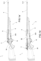
- a firearm in the entirety thereof, according to this invention is indicated with the numeral 1.
- the firearm 1 is a rifle.
- the firearm 1 comprises a plurality of components which, by convention, are defined as fixed, and a plurality of components which are defined as movable.
- the firearm 1 comprises a fixed main body 2.
- a main body 2 is graspable or embraceable by the user for example in shooting or aiming operations, comprising a stock and/or a forend.
- the fixed body 2 comprises a barrel 4 extending along an axis X-X.
- the axis X-X is therefore the axis of the barrel.
- axial refers to movements or characteristics or components that occur or that are positioned parallel to said axis X-X, i.e., parallel to the barrel 4. In some cases such movements or features or components are along the barrel axis X-X.
- axial the term “longitudinal” is also used.
- the main body 2 comprises a receiver 6.
- the receiver 6 is made from a material belonging to the family of metals or metal alloys, or polymers, or polymeric materials, or composite materials.
- the receiver 6 has an upper opening 60.
- the receiver 6 has an opening 60 facing in the vertical direction.
- the receiver 6 is a receiver "without a castle”.
- the receiver 6 is a hollow component that is suitable for containing components, shooting mechanisms, and projectiles.
- the barrel 4 extends from the receiver 6.
- the stock extends from the receiver 6.
- the forend extends from the receiver 6.
- the receiver 6 also comprises a lower opening 65. Projectiles enter through said lower opening 65.
- a magazine 500 is accommodated inside the receiver 6.
- the magazine 500 is inserted through said lower opening 65.
- the magazine 500 closes said lower opening 65.
- said receiver 6 is hollow and comprises a housing cavity 600.
- the main body 2 also comprises a breech element 8 positioned at an axial end of said upper opening 60.
- the breech element 8 extends in height, preferably in a vertical direction.
- the barrel 4 is mountable onto the breech element 8 at an end opposite the firing mouth of the barrel 4.
- the breech element 8 is comprised within the barrel 4: the breech element 8 is the axial end opposite the firing mouth of the barrel 4.
- the aforementioned components, listed in a non-limiting manner, that are part of the main body 2 are all mutually distinct components.
- the aforementioned components, listed in a non-limiting way, that are part of the main body 2 are sometimes mutually connected: some components are integrally connected together.
- the firearm 1 comprises a carriage assembly 3 comprising a shutter group 5.
- the shutter group 5 also comprises engageable firing striker members.
- the carriage assembly 3 comprises components, the movements and actuations of which involve a firing action and a reloading action, i.e., discharging the exploded cartridge case to the outside and loading the projectile from the magazine 500.
- the carriage assembly 3 is positioned on the receiver 6 at the upper opening 60.
- the carriage assembly 3 is positioned and is shaped in a suitable way to close said upper opening 60.
- the carriage assembly 3 slides on the axial edges 600 delimiting the upper opening.
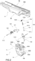
- the firearm 1 comprises a trigger group 10 operable by the user in order to perform the shooting action.
- the trigger group 10 interacts with said shutter group 5, in particular with the striker members.
- the trigger group 10 comprises a trigger 100.
- the trigger 100 is rotatable relative to a trigger axis G-G.
- the trigger 100 is pivoted on a pin extending along the trigger axis G-G.
- said trigger axis G-G extends transversely.
- the trigger group 10 comprises a hammer device 120 engaged by the trigger 100.
- the hammer device 120 comprises a trigger lever 121 suitable for rotating with respect to a hammer axis C-C.
- the hammer device 120 comprises a hammer spring 125 suitable for exerting a pushing action against the hammer lever 121.
- the trigger 100 and the hammer lever 121 are suitable for being engaged.
- the actuation of the trigger 100 results in releasing the mutual engagement between the trigger 100 and the hammer lever 121 and the latter is subject to rotation and in particular the engagement of the shutter group 3, resulting in the shooting action.
- the trigger group 10 comprises an adjustment device 150 suitable for adjusting the intensity necessary to operate the trigger 100.
- the adjustment device 150 is configurable in a plurality of distinct configurations, in each of which a different action on the trigger 100 is produced.
- the adjustment device 150 comprises a rod 151 movable by the trigger 100.
- the adjustment device 150 comprises a command member 152 engaged with the rod 151.
- said engagement of the command member 152 on the rod 151 affects the action of the trigger 100.
- the command member 152 is positionable on the rod 151 in a predefined axial operating position, wherein the rod 151 is slidably engaged with the command member 152. Conversely, the command member 152 is slidably engaged with the rod 151.
- the adjustment device 150 comprises a thrust spring 155 that is suitable for exerting a thrust action that discharges onto the trigger 100.
- said thrust spring 155 acts on the rod 151 between the trigger end 1511 and the command member 152.
- the thrust spring 155 is fitted to the rod 151.
- the rod 151 extends along the thrust spring 155.
- the elastic action of the thrust spring 155 on the trigger 100 is a function of the axial operating position of the command member 152.
- the trigger 100 comprises an engagement portion 110 with which the trigger end 1511 of the rod 151 is engaged.
- the trigger end 1511 is hinged or pivoted on the engagement portion 110.
- the engagement portion 110 is positioned radially spaced apart from the trigger axis G-G.
- the command member 152 is positionable in at least two, preferably three, distinct operating positions.
- the command member 152 is positionable in such a way that the thrust spring 155 is suitable for performing at least two, preferably three, distinct thrust actions on the trigger 100.
- the command member 152 is movable by a user in order to position it in a preferred operating position, corresponding to a preferred position along the rod 151.
- the user without the aid of components, and/or without having to disassemble certain components, adjusts the position of the command member 152, thus varying the trigger setting.
- the command member 152 comprises a command button 1520 engageable by a user.
- the command button 1520 is operable by means of interacting with a fingertip.
- the command button 1520 has a knurled surface engageable by the user.
- the command member 152 comprises a protruding element 1522, extending from said command button 1520 and engaging the rod 151.
- the protruding element 1522 comprises a through hole 1520' through which the rod 151 is accommodated.
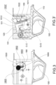
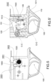
- the trigger assembly 10 comprises an adjustment region 180 engageable by the command member 152.
- the command member 152 is movable and positionable in a plurality of predefined positions within said adjustment region 180.
- said adjustment region 180 comprises an adjustment opening 1800 crossed by the command member 152.
- the command button 1520 is positioned on one side of the adjustment region 180, and the rod 151 and the through hole 1520' are positioned on the other side.
- said adjustment opening 1800 comprises at least two, preferably three, adjustment areas 1801, 1802, 1803 in which the command member 152 is fixedly positionable.
- the adjustment opening 1800 is shaped in such a way to have a sliding area 1805 joining the adjustment areas 1801, 1802, 1803.
- the movements of the command member 152 are guided by the shape and by the edges of the adjustment opening 1800.
- the adjustment opening 1800 is surrounded by an adjustment slot 1850 suitable for guiding the adjustment button 1520.
- the sliding area 1805 is substantially linear, and at least one, preferably at least two, adjustment areas 1801, 1802, 1803 are transverse to the sliding area 1805.
- the first adjustment area 1801 is positioned at an axial end of the sliding area 1805.
- the adjustment opening 1800 is substantially comb-shaped, thus determining a sliding area 1805 that joins the various adjustment areas 1801, 1802, 1803.
- the adjustment areas 1801, 1802, 1803 are shaped in such a way to prevent an undesired change in the position of the command member 182.
- some adjustment areas 1801, 1802, 1803 have edges or abutments suitable for holding the command member 182 in position.
- the action of the thrust spring 151 and the shape of the adjustment areas 1801, 1802, 1803 hold the command member 182 in position.
- the user in order to vary the position of the command member 182, the user must overcome the action of the thrust spring 151 by passing over said edges or abutments.
- the positioning of the command member 152 within an adjustment area distal from the engagement portion 110 of the trigger 100 corresponds to a lower thrust action of the thrust spring 155, and therefore to a softer action of the trigger 100, and therefore a lower trigger weight.
- the positioning of the command member 152 within an adjustment area near to the engagement portion 110 of the trigger 100 corresponds to a higher thrust action of the thrust spring 155, and therefore to a harder action of the trigger 100, and therefore a higher trigger weight.
- each adjustment area performs a compression action against the thrust spring 155, increasing the trigger weight from 100 to 300 grams, preferably by about 200 grams, compared to the previous adjustment region.
- the trigger assembly 10 comprises a trigger box 11 accommodating the adjustment device 150 and a trigger portion 100, in which said trigger box 11 is removably insertable into the firearm 1.
- the adjustment region 180 is formed on a side wall 13 of the trigger box 11.
- the adjustment opening 180 passes through a side wall 13.
- said trigger box 10 is insertable into the receiver 6 through the lower opening 65.
- the side walls 13 of the trigger box 11 engage the side walls of the receiver 6.
- such walls are specially shaped with rails and guides suitable for allowing such mutual engagement.
- rails and guides extend axially.
- the trigger box 11 is insertable through the receiver 6 first in a vertical direction, then in an axial direction.
- the trigger 100 partially protrudes from the trigger box 11 accommodated in the receiver 6.
- the lower area of the trigger box 11 comprises a handguard 14.
- the firearm which is the object of the present invention is an alternative solution to those that are known.
- the trigger group is adjustable by means of simple and intuitive operations.
- the adjustment operations are error-proof.
- the adjustment operations are guided.
- the trigger group assembly and/or replacement operations are simplified and intuitive.
Landscapes
- Engineering & Computer Science (AREA)
- General Engineering & Computer Science (AREA)
- Aiming, Guidance, Guns With A Light Source, Armor, Camouflage, And Targets (AREA)
Claims (14)
- Schusswaffe (1), vorzugsweise ein Gewehr, mit einer Abzugsgruppe (10), die von dem Benutzer zum Befehlen bzw. Auslösen einer Schussaktion betätigbar ist, wobei die Abzugsgruppe (10) einen Abzug (100), der in Bezug auf eine Abzugsachse (G-G) drehbar ist, und eine Einstellvorrichtung (150) umfasst, die zum Einstellen der zum Betätigen des Abzugs (100) erforderlichen Intensität geeignet ist, umfassend:- eine Stange (151), die durch den Abzug (100) bewegbar ist und sich axial zwischen einem Abzugsende (1511) und einem freien Ende (1512) erstreckt;- ein Befehls- bzw. Auslöseglied (152), das mit der Stange (151) in Eingriff ist und in einer vorbestimmten axialen Betätigungsposition positionierbar ist, wobei die Stange (151) verschiebbar mit dem Auslöseglied (152) in Eingriff ist;- eine Druckfeder (155), die auf die Stange (151) zwischen dem Abzugsende (1511) und dem Auslöseglied (152) wirkt,wobei die elastische Wirkung der Druckfeder (155) auf den Abzug (100) eine Funktion der axialen Betätigungsposition des Auslöseglieds (152) ist;wobei die Schusswaffe (1) dadurch gekennzeichnet ist, dass die Abzugsgruppe (10) einen Einstellbereich (180) umfasst, in den das Auslöseglied (152) eingreifen kann, wobei der Einstellbereich (180) eine Einstellöffnung (1800) umfasst, die von dem Auslöseglied (152) durchquert wird, wobei die Einstellöffnung (1800) zumindest zwei, vorzugsweise drei Einstellbereiche (1801, 1802, 1803) umfasst, in denen das Auslöseglied (152) fest positionierbar ist.
- Schusswaffe (1) nach Anspruch 1, wobei der Abzug (100) einen Eingriffsabschnitt (110) umfasst, mit dem das Abzugsende (1511) der Stange (151) in Eingriff ist.
- Schusswaffe (1) nach einem der vorhergehenden Ansprüche, wobei das Auslöseglied (152) in zumindest zwei, vorzugsweise drei verschiedenen Betätigungspositionen positioniert ist.
- Schusswaffe (1) nach Anspruch 3, wobei das Auslöseglied (152) von einem Benutzer bewegt werden kann, um es in einer bevorzugten Betätigungsposition, die einer bevorzugten Position entspricht, entlang der Stange (151) zu positionieren.
- Schusswaffe (1) nach Anspruch 3, wobei das Auslöseglied (152) einen Befehls- bzw. Auslöseknopf (1520) und ein vorstehendes Element (1522) umfasst, das sich von dem Auslöseknopf (1520) erstreckt und in die Stange (151) eingreift und diese in einem Durchgangsloch (1520') aufnimmt.
- Schusswaffe (1) nach einem der vorhergehenden Ansprüche, wobei die Einstellöffnung (1800) so geformt ist, dass sie einen Gleitbereich (1805) zum Verbinden der bzw. zwischen den Einstellbereichen (1801, 1802, 1803) aufweist.
- Schusswaffe (1) nach Anspruch 6, wobei der Gleitbereich (1805) im Wesentlichen linear ist und zumindest ein, vorzugsweise zumindest zwei Einstellbereiche (1801, 1802, 1803) quer zu dem Gleitbereich (1805) sind.
- Schusswaffe (1) nach einem der vorhergehenden Ansprüche, wobei die Abzugsgruppe (10) eine Hammervorrichtung (120) umfasst, in die der Abzug (100) eingreift.
- Schusswaffe (1) nach einem der vorhergehenden Ansprüche, wobei die Abzugsgruppe (10) einen Abzugskasten (11), der die Einstellvorrichtung (150) aufnimmt, und einen Abzugsabschnitt (100) umfasst, in dem der Abzugskasten (11) entfernbar in die Schusswaffe (1) einsetzbar ist.
- Schusswaffe (1) nach Anspruch 9, wobei der Einstellbereich (180) an einer Seitenwand (13) des Abzugskastens (11) enthalten bzw. ausgebildet ist.
- Schusswaffe (1) nach Anspruch 10, wobei die Einstellöffnung (180) durch eine Seitenwand (13) verläuft.
- Schusswaffe (1) nach einem der vorhergehenden Ansprüche, umfassend einen festen Hauptkörper (2), umfassend einen Gehäusehohlraum (600), in dem die Abzugsgruppe (10), insbesondere der Abzugskasten (11), entfernbar aufnehmbar ist.
- Schusswaffe (1) nach Anspruch 12, wobei der feste Körper (2) einen Lauf (4), der sich entlang einer Laufachse (X-X) erstreckt, und einen Empfänger (6) umfasst, von bzw. aus dem sich der Lauf (4) erstreckt, wobei der Empfänger eine obere Öffnung (60) und eine untere Öffnung (65) umfasst, wobei die Waffe zudem eine Schlittenanordnung (3) umfasst, die durch die an dem Empfänger (6) positionierte Abzugsgruppe (10) zum Verschließen der oberen Öffnung (60) betätigbar ist, wobei die Schusswaffe ein Magazin (500) umfasst, das in die untere Öffnung (65) einsetzbar ist, in die bzw. wobei der Abzugskasten (11) durch die untere Öffnung (65) in den Empfänger (6) einsetzbar ist.
- Schusswaffe (1) nach einem der vorhergehenden Ansprüche, wobei die Schusswaffe (1) ein Gewehr ist.
Applications Claiming Priority (1)
| Application Number | Priority Date | Filing Date | Title |
|---|---|---|---|
| IT102021000026657A IT202100026657A1 (it) | 2021-10-18 | 2021-10-18 | Arma con gruppo scatto comprendente un dispositivo di regolazione |
Publications (2)
| Publication Number | Publication Date |
|---|---|
| EP4166894A1 EP4166894A1 (de) | 2023-04-19 |
| EP4166894B1 true EP4166894B1 (de) | 2025-02-19 |
Family
ID=79601666
Family Applications (1)
| Application Number | Title | Priority Date | Filing Date |
|---|---|---|---|
| EP22199775.2A Active EP4166894B1 (de) | 2021-10-18 | 2022-10-05 | Feuerwaffe mit einer eine verstelleinrichtung aufweisenden abzugsgruppe |
Country Status (3)
| Country | Link |
|---|---|
| US (1) | US11774201B2 (de) |
| EP (1) | EP4166894B1 (de) |
| IT (1) | IT202100026657A1 (de) |
Families Citing this family (1)
| Publication number | Priority date | Publication date | Assignee | Title |
|---|---|---|---|---|
| DE102024128120A1 (de) | 2024-09-27 | 2026-04-02 | AKILA d.o.o. | Abzugsmechanismus |
Family Cites Families (8)
| Publication number | Priority date | Publication date | Assignee | Title |
|---|---|---|---|---|
| GB162484A (en) * | 1920-03-13 | 1921-05-05 | Moubray Gore Farquhar | Improvements in or relating to automatic fire arms |
| BR7908531A (pt) * | 1979-12-27 | 1981-06-30 | Forjas Taurus Sa | Aperfeicoamento no sistema impulsor para o retorno do gatilho em revolveres de acao-dupla |
| DE3639746C1 (de) * | 1986-11-21 | 1988-05-26 | Erma Werke Waffen & Maschf | Vorrichtung zum Verstellen des Abzugsgewichtes eines Trommelrevolvers |
| US7562479B2 (en) * | 2005-02-28 | 2009-07-21 | Denny Williams | Set trigger for a firearm |
| RU2470249C1 (ru) * | 2011-06-08 | 2012-12-20 | Общество С Ограниченной Ответственностью "Промтехнология" | Спусковой механизм |
| DE202015101485U1 (de) * | 2015-03-24 | 2016-06-28 | L&O Hunting Group GmbH | Abzugseinrichtung einer Handfeuerwaffe |
| RU2652859C1 (ru) * | 2017-03-06 | 2018-05-03 | Открытое акционерное общество "Завод им. В.А. Дегтярева" | Регулируемый спусковой механизм огнестрельного оружия |
| CN113720203B (zh) * | 2021-09-13 | 2025-10-31 | 常旬 | 扳机具有力度调节、带激光瞄准的训练枪 |
-
2021
- 2021-10-18 IT IT102021000026657A patent/IT202100026657A1/it unknown
-
2022
- 2022-10-05 EP EP22199775.2A patent/EP4166894B1/de active Active
- 2022-10-18 US US17/968,647 patent/US11774201B2/en active Active
Also Published As
| Publication number | Publication date |
|---|---|
| US20230122034A1 (en) | 2023-04-20 |
| EP4166894A1 (de) | 2023-04-19 |
| US11774201B2 (en) | 2023-10-03 |
| IT202100026657A1 (it) | 2023-04-18 |
Similar Documents
| Publication | Publication Date | Title |
|---|---|---|
| EP3129739B1 (de) | Abzugssystem für feuerwaffen | |
| US9714804B2 (en) | Firearm with safe axis firing pin and center aligned barrel | |
| CA2675219C (en) | Control element, firing unit and firing assembly for a weapon | |
| US20170241729A1 (en) | Bolt Catch for a Rifle | |
| WO2013103428A2 (en) | Ambidextrous rifle bolt stop release | |
| PT2350550E (pt) | Armas de fogo de recuo retardado com novos mecanismos para o controle do recuo e subida da boca | |
| EP4166895B1 (de) | Gewehr | |
| US11656040B2 (en) | Bolt stop with a locking device for an automatic firearm, and a grip stock and receiver equipped therewith | |
| US10989490B2 (en) | Firearm and methods for operation and manufacture thereof | |
| EP4166894B1 (de) | Feuerwaffe mit einer eine verstelleinrichtung aufweisenden abzugsgruppe | |
| EP4166890B1 (de) | Gewehr mit rückstossgruppe | |
| US11761720B2 (en) | Carbine having a charging handle | |
| EP4166891B1 (de) | Gewehr mit sicherheitsgruppe | |
| KR102896483B1 (ko) | 가스 블록 | |
| WO2025174403A2 (en) | Additive metal rifle systems and manufacturing methods | |
| US20220065577A1 (en) | Trigger device for a buttstock loader | |
| EP4166892B1 (de) | Gewehr mit verschlussgruppe | |
| KR102812247B1 (ko) | 화기용 브리치블록 어셈블리 및 관련 화기 | |
| WO2023229560A1 (en) | Ergonomic rifle with a mechanizm holder | |
| EP4533019A1 (de) | Ergonomisches gewehr mit einem mechanischen halter | |
| HU218320B (en) | Mechanism promoting readiness to fire for repeating small arms |
Legal Events
| Date | Code | Title | Description |
|---|---|---|---|
| PUAI | Public reference made under article 153(3) epc to a published international application that has entered the european phase |
Free format text: ORIGINAL CODE: 0009012 |
|
| STAA | Information on the status of an ep patent application or granted ep patent |
Free format text: STATUS: THE APPLICATION HAS BEEN PUBLISHED |
|
| AK | Designated contracting states |
Kind code of ref document: A1 Designated state(s): AL AT BE BG CH CY CZ DE DK EE ES FI FR GB GR HR HU IE IS IT LI LT LU LV MC ME MK MT NL NO PL PT RO RS SE SI SK SM TR |
|
| STAA | Information on the status of an ep patent application or granted ep patent |
Free format text: STATUS: REQUEST FOR EXAMINATION WAS MADE |
|
| 17P | Request for examination filed |
Effective date: 20230511 |
|
| RBV | Designated contracting states (corrected) |
Designated state(s): AL AT BE BG CH CY CZ DE DK EE ES FI FR GB GR HR HU IE IS IT LI LT LU LV MC ME MK MT NL NO PL PT RO RS SE SI SK SM TR |
|
| P01 | Opt-out of the competence of the unified patent court (upc) registered |
Effective date: 20230522 |
|
| GRAP | Despatch of communication of intention to grant a patent |
Free format text: ORIGINAL CODE: EPIDOSNIGR1 |
|
| STAA | Information on the status of an ep patent application or granted ep patent |
Free format text: STATUS: GRANT OF PATENT IS INTENDED |
|
| RIN1 | Information on inventor provided before grant (corrected) |
Inventor name: SPOTO, CALOGERO Inventor name: PLEBANI, ENNIO |
|
| INTG | Intention to grant announced |
Effective date: 20241030 |
|
| GRAS | Grant fee paid |
Free format text: ORIGINAL CODE: EPIDOSNIGR3 |
|
| GRAA | (expected) grant |
Free format text: ORIGINAL CODE: 0009210 |
|
| STAA | Information on the status of an ep patent application or granted ep patent |
Free format text: STATUS: THE PATENT HAS BEEN GRANTED |
|
| AK | Designated contracting states |
Kind code of ref document: B1 Designated state(s): AL AT BE BG CH CY CZ DE DK EE ES FI FR GB GR HR HU IE IS IT LI LT LU LV MC ME MK MT NL NO PL PT RO RS SE SI SK SM TR |
|
| REG | Reference to a national code |
Ref country code: GB Ref legal event code: FG4D |
|
| REG | Reference to a national code |
Ref country code: CH Ref legal event code: EP |
|
| REG | Reference to a national code |
Ref country code: DE Ref legal event code: R096 Ref document number: 602022010759 Country of ref document: DE |
|
| REG | Reference to a national code |
Ref country code: IE Ref legal event code: FG4D |
|
| REG | Reference to a national code |
Ref country code: SE Ref legal event code: TRGR |
|
| REG | Reference to a national code |
Ref country code: NL Ref legal event code: MP Effective date: 20250219 |
|
| PG25 | Lapsed in a contracting state [announced via postgrant information from national office to epo] |
Ref country code: RS Free format text: LAPSE BECAUSE OF FAILURE TO SUBMIT A TRANSLATION OF THE DESCRIPTION OR TO PAY THE FEE WITHIN THE PRESCRIBED TIME-LIMIT Effective date: 20250519 |
|
| PG25 | Lapsed in a contracting state [announced via postgrant information from national office to epo] |
Ref country code: FI Free format text: LAPSE BECAUSE OF FAILURE TO SUBMIT A TRANSLATION OF THE DESCRIPTION OR TO PAY THE FEE WITHIN THE PRESCRIBED TIME-LIMIT Effective date: 20250219 |
|
| PG25 | Lapsed in a contracting state [announced via postgrant information from national office to epo] |
Ref country code: PL Free format text: LAPSE BECAUSE OF FAILURE TO SUBMIT A TRANSLATION OF THE DESCRIPTION OR TO PAY THE FEE WITHIN THE PRESCRIBED TIME-LIMIT Effective date: 20250219 |
|
| PG25 | Lapsed in a contracting state [announced via postgrant information from national office to epo] |
Ref country code: ES Free format text: LAPSE BECAUSE OF FAILURE TO SUBMIT A TRANSLATION OF THE DESCRIPTION OR TO PAY THE FEE WITHIN THE PRESCRIBED TIME-LIMIT Effective date: 20250219 |
|
| REG | Reference to a national code |
Ref country code: LT Ref legal event code: MG9D |
|
| PG25 | Lapsed in a contracting state [announced via postgrant information from national office to epo] |
Ref country code: NO Free format text: LAPSE BECAUSE OF FAILURE TO SUBMIT A TRANSLATION OF THE DESCRIPTION OR TO PAY THE FEE WITHIN THE PRESCRIBED TIME-LIMIT Effective date: 20250519 Ref country code: IS Free format text: LAPSE BECAUSE OF FAILURE TO SUBMIT A TRANSLATION OF THE DESCRIPTION OR TO PAY THE FEE WITHIN THE PRESCRIBED TIME-LIMIT Effective date: 20250619 |
|
| PG25 | Lapsed in a contracting state [announced via postgrant information from national office to epo] |
Ref country code: NL Free format text: LAPSE BECAUSE OF FAILURE TO SUBMIT A TRANSLATION OF THE DESCRIPTION OR TO PAY THE FEE WITHIN THE PRESCRIBED TIME-LIMIT Effective date: 20250219 |
|
| PG25 | Lapsed in a contracting state [announced via postgrant information from national office to epo] |
Ref country code: HR Free format text: LAPSE BECAUSE OF FAILURE TO SUBMIT A TRANSLATION OF THE DESCRIPTION OR TO PAY THE FEE WITHIN THE PRESCRIBED TIME-LIMIT Effective date: 20250219 |
|
| PG25 | Lapsed in a contracting state [announced via postgrant information from national office to epo] |
Ref country code: LV Free format text: LAPSE BECAUSE OF FAILURE TO SUBMIT A TRANSLATION OF THE DESCRIPTION OR TO PAY THE FEE WITHIN THE PRESCRIBED TIME-LIMIT Effective date: 20250219 Ref country code: PT Free format text: LAPSE BECAUSE OF FAILURE TO SUBMIT A TRANSLATION OF THE DESCRIPTION OR TO PAY THE FEE WITHIN THE PRESCRIBED TIME-LIMIT Effective date: 20250620 |
|
| PG25 | Lapsed in a contracting state [announced via postgrant information from national office to epo] |
Ref country code: BG Free format text: LAPSE BECAUSE OF FAILURE TO SUBMIT A TRANSLATION OF THE DESCRIPTION OR TO PAY THE FEE WITHIN THE PRESCRIBED TIME-LIMIT Effective date: 20250219 Ref country code: GR Free format text: LAPSE BECAUSE OF FAILURE TO SUBMIT A TRANSLATION OF THE DESCRIPTION OR TO PAY THE FEE WITHIN THE PRESCRIBED TIME-LIMIT Effective date: 20250520 |
|
| REG | Reference to a national code |
Ref country code: AT Ref legal event code: MK05 Ref document number: 1768626 Country of ref document: AT Kind code of ref document: T Effective date: 20250219 |
|
| PG25 | Lapsed in a contracting state [announced via postgrant information from national office to epo] |
Ref country code: SM Free format text: LAPSE BECAUSE OF FAILURE TO SUBMIT A TRANSLATION OF THE DESCRIPTION OR TO PAY THE FEE WITHIN THE PRESCRIBED TIME-LIMIT Effective date: 20250219 |
|
| PG25 | Lapsed in a contracting state [announced via postgrant information from national office to epo] |
Ref country code: DK Free format text: LAPSE BECAUSE OF FAILURE TO SUBMIT A TRANSLATION OF THE DESCRIPTION OR TO PAY THE FEE WITHIN THE PRESCRIBED TIME-LIMIT Effective date: 20250219 |
|
| PGFP | Annual fee paid to national office [announced via postgrant information from national office to epo] |
Ref country code: TR Payment date: 20250922 Year of fee payment: 4 |
|
| PG25 | Lapsed in a contracting state [announced via postgrant information from national office to epo] |
Ref country code: AT Free format text: LAPSE BECAUSE OF FAILURE TO SUBMIT A TRANSLATION OF THE DESCRIPTION OR TO PAY THE FEE WITHIN THE PRESCRIBED TIME-LIMIT Effective date: 20250219 |
|
| PGFP | Annual fee paid to national office [announced via postgrant information from national office to epo] |
Ref country code: FR Payment date: 20250930 Year of fee payment: 4 |
|
| PG25 | Lapsed in a contracting state [announced via postgrant information from national office to epo] |
Ref country code: EE Free format text: LAPSE BECAUSE OF FAILURE TO SUBMIT A TRANSLATION OF THE DESCRIPTION OR TO PAY THE FEE WITHIN THE PRESCRIBED TIME-LIMIT Effective date: 20250219 |
|
| PG25 | Lapsed in a contracting state [announced via postgrant information from national office to epo] |
Ref country code: RO Free format text: LAPSE BECAUSE OF FAILURE TO SUBMIT A TRANSLATION OF THE DESCRIPTION OR TO PAY THE FEE WITHIN THE PRESCRIBED TIME-LIMIT Effective date: 20250219 |
|
| PG25 | Lapsed in a contracting state [announced via postgrant information from national office to epo] |
Ref country code: SK Free format text: LAPSE BECAUSE OF FAILURE TO SUBMIT A TRANSLATION OF THE DESCRIPTION OR TO PAY THE FEE WITHIN THE PRESCRIBED TIME-LIMIT Effective date: 20250219 |
|
| REG | Reference to a national code |
Ref country code: DE Ref legal event code: R097 Ref document number: 602022010759 Country of ref document: DE |
|
| PLBE | No opposition filed within time limit |
Free format text: ORIGINAL CODE: 0009261 |
|
| STAA | Information on the status of an ep patent application or granted ep patent |
Free format text: STATUS: NO OPPOSITION FILED WITHIN TIME LIMIT |
|
| PGFP | Annual fee paid to national office [announced via postgrant information from national office to epo] |
Ref country code: DE Payment date: 20251027 Year of fee payment: 4 |
|
| PGFP | Annual fee paid to national office [announced via postgrant information from national office to epo] |
Ref country code: IT Payment date: 20251031 Year of fee payment: 4 |
|
| PGFP | Annual fee paid to national office [announced via postgrant information from national office to epo] |
Ref country code: BE Payment date: 20251021 Year of fee payment: 4 |
|
| PGFP | Annual fee paid to national office [announced via postgrant information from national office to epo] |
Ref country code: SE Payment date: 20251022 Year of fee payment: 4 |
|
| PGFP | Annual fee paid to national office [announced via postgrant information from national office to epo] |
Ref country code: CZ Payment date: 20250930 Year of fee payment: 4 |
|
| 26N | No opposition filed |
Effective date: 20251120 |