EP4166891B1 - Gewehr mit sicherheitsgruppe - Google Patents
Gewehr mit sicherheitsgruppe Download PDFInfo
- Publication number
- EP4166891B1 EP4166891B1 EP22199815.6A EP22199815A EP4166891B1 EP 4166891 B1 EP4166891 B1 EP 4166891B1 EP 22199815 A EP22199815 A EP 22199815A EP 4166891 B1 EP4166891 B1 EP 4166891B1
- Authority
- EP
- European Patent Office
- Prior art keywords
- safety
- rifle
- lever
- configuration
- hammer
- Prior art date
- Legal status (The legal status is an assumption and is not a legal conclusion. Google has not performed a legal analysis and makes no representation as to the accuracy of the status listed.)
- Active
Links
Images


Classifications
-
- F—MECHANICAL ENGINEERING; LIGHTING; HEATING; WEAPONS; BLASTING
- F41—WEAPONS
- F41A—FUNCTIONAL FEATURES OR DETAILS COMMON TO BOTH SMALLARMS AND ORDNANCE, e.g. CANNONS; MOUNTINGS FOR SMALLARMS OR ORDNANCE
- F41A17/00—Safety arrangements, e.g. safeties
- F41A17/74—Hammer safeties, i.e. means for preventing the hammer from hitting the cartridge or the firing pin
-
- F—MECHANICAL ENGINEERING; LIGHTING; HEATING; WEAPONS; BLASTING
- F41—WEAPONS
- F41A—FUNCTIONAL FEATURES OR DETAILS COMMON TO BOTH SMALLARMS AND ORDNANCE, e.g. CANNONS; MOUNTINGS FOR SMALLARMS OR ORDNANCE
- F41A17/00—Safety arrangements, e.g. safeties
- F41A17/20—Grip or stock safeties, i.e. safeties disengaged by clasping the grip or stock
- F41A17/26—Grip or stock safeties, i.e. safeties disengaged by clasping the grip or stock acting on the hammer
-
- F—MECHANICAL ENGINEERING; LIGHTING; HEATING; WEAPONS; BLASTING
- F41—WEAPONS
- F41A—FUNCTIONAL FEATURES OR DETAILS COMMON TO BOTH SMALLARMS AND ORDNANCE, e.g. CANNONS; MOUNTINGS FOR SMALLARMS OR ORDNANCE
- F41A17/00—Safety arrangements, e.g. safeties
- F41A17/42—Safeties for locking the breech-block or bolt in a safety position
-
- F—MECHANICAL ENGINEERING; LIGHTING; HEATING; WEAPONS; BLASTING
- F41—WEAPONS
- F41A—FUNCTIONAL FEATURES OR DETAILS COMMON TO BOTH SMALLARMS AND ORDNANCE, e.g. CANNONS; MOUNTINGS FOR SMALLARMS OR ORDNANCE
- F41A17/00—Safety arrangements, e.g. safeties
- F41A17/74—Hammer safeties, i.e. means for preventing the hammer from hitting the cartridge or the firing pin
- F41A17/80—Thumb-operated sliding safeties mounted on the upside of the stock, e.g. for shotguns
-
- F—MECHANICAL ENGINEERING; LIGHTING; HEATING; WEAPONS; BLASTING
- F41—WEAPONS
- F41A—FUNCTIONAL FEATURES OR DETAILS COMMON TO BOTH SMALLARMS AND ORDNANCE, e.g. CANNONS; MOUNTINGS FOR SMALLARMS OR ORDNANCE
- F41A19/00—Firing or trigger mechanisms; Cocking mechanisms
- F41A19/06—Mechanical firing mechanisms, e.g. counterrecoil firing, recoil actuated firing mechanisms
- F41A19/14—Hammers, i.e. pivotably-mounted striker elements; Hammer mountings
-
- F—MECHANICAL ENGINEERING; LIGHTING; HEATING; WEAPONS; BLASTING
- F41—WEAPONS
- F41A—FUNCTIONAL FEATURES OR DETAILS COMMON TO BOTH SMALLARMS AND ORDNANCE, e.g. CANNONS; MOUNTINGS FOR SMALLARMS OR ORDNANCE
- F41A3/00—Breech mechanisms, e.g. locks
- F41A3/12—Bolt action, i.e. the main breech opening movement being parallel to the barrel axis
- F41A3/14—Rigid bolt locks, i.e. having locking elements rigidly mounted on the bolt or bolt handle and on the barrel or breech-housing respectively
- F41A3/16—Rigid bolt locks, i.e. having locking elements rigidly mounted on the bolt or bolt handle and on the barrel or breech-housing respectively the locking elements effecting a rotary movement about the barrel axis, e.g. rotating cylinder bolt locks
- F41A3/18—Rigid bolt locks, i.e. having locking elements rigidly mounted on the bolt or bolt handle and on the barrel or breech-housing respectively the locking elements effecting a rotary movement about the barrel axis, e.g. rotating cylinder bolt locks hand-operated
- F41A3/20—Straight-pull operated bolt locks, i.e. the operating hand effecting only a straight movement parallel to the barrel axis
Definitions
- the present invention relates to a rifle.
- the present invention relates to a rifle preferably, but not necessarily, for hunting.
- the rifle which is the object of the present invention is of the type in which the rearming operations are performed by the user by axially manually moving the carriage assembly.
- embodiments of rifles which comprise a fixed main body which may be gripped by the user, and a carriage assembly which may be manually moved by the user to rearm the shot.
- the carriage assembly is known to move between an advanced configuration and a retracted configuration and vice versa.
- such known rifle solutions comprise a rearming trigger, or rearming lever, which may be gripped by the user to carry out the aforesaid operations.
- the known solutions of rifles of this type include solutions comprising a trigger group of the "striker fired" type.
- the actuation of the trigger involves an actuation of the striker whose kinetic inertia is due to the presence of a preloaded spring.
- rifle solutions which comprise a trigger group with a hammer device.
- both said types of rifles comprise carriage assemblies that feature reduced axial strokes, having complex interaction operations with the bullet to be shot and with the cartridge case of the exploded bullet.
- the object of the present invention is to provide an alternative rifle solution to such known solutions of the prior art, having a hammer device but guaranteeing simple movements of the carriage assembly.
- the rifle solution which is the object of the present invention has all the technical advantages linked to said type of trigger group with a hammer device and at the same time all the possible advantages from solutions in which large strokes of the carriage assembly are possible.
- a rifle according to this invention is indicated with the numeral 1 in its entirety.
- the rifle 1 which is the object of the present invention comprises a plurality of components which by convention are defined as fixed, and a plurality of components which are defined as movable.
- the rifle 1 comprises a fixed main body 2.
- This main body 2 is grippable or embraceable by the user, for example in shooting or aiming operations, comprising a stock and/or forend.
- the fixed body 2 comprises a barrel 4 which extends along an axis X-X.
- the axis X-X is therefore the barrel axis.
- axial refers to movements or characteristics or components which occur or which are positioned parallel to said axis X-X, i.e. parallel to the barrel 4. In some cases, such movements or characteristics or components are along the barrel axis X-X.
- axial the term “longitudinal” is also used.
- the main body 2 comprises a receiver 6.
- the receiver 6 is made of a material belonging to the family of metals or metal alloys, or polymers, or polymeric materials, or composite materials.
- the receiver 6 has an upper opening 60.
- the receiver 6 has an opening 60 facing the vertical direction.
- the receiver 6 is a receiver "without a castle”.
- the receiver 6 is a hollow component suitable for containing components, shooting mechanisms, and bullets.
- the barrel 4 extends from the receiver 6.
- the stock extends from the receiver 6.
- the forend extends from the receiver 6.
- the receiver 6 also comprises a lower opening 65.
- the bullets enter through said lower opening 65.
- a loader 500 is housed in the receiver 6.
- the loader 500 is inserted through said lower opening 65.
- the loader 500 closes said lower opening 65.
- the main body 2 also comprises a breech element 8 positioned at an axial end of said upper opening 60.
- the breech element 8 extends in height, preferably in a vertical direction.
- the barrel 4 is mountable to the breech element 8 at an opposite end from the firing mouth of the barrel 4.
- the breech element 8 is included in the barrel 4: the breech element 8 is the axial end opposite the firing mouth of the barrel 4.
- the aforementioned components, listed in a non-limiting manner, that form part of the main body 2 are all mutually distinct components.
- the aforementioned components, listed in a non-limiting manner, that form part of the main body 2 are sometimes mutually integral: some components are mutually integrally connected to each other.
- the rifle 2 comprises a trigger group 10 operable by the user to carry out the shooting action.
- the trigger group 10 is at least partially housed in the receiver 6.
- Said trigger group 10 comprises a trigger 100.
- said trigger 100 is rotationally movable about a trigger axis G-G.
- the trigger axis G-G has a substantially transverse extension.
- Said trigger group comprises a trigger spring 101 which acts on the trigger 100.
- said trigger spring 101 is an axial spring.
- the trigger group 10 further comprises a hammer device 110 operable by the trigger 100.
- the hammer device 110 comprises a hammer lever 111 which is rotationally movable about a hammer axis C-C.
- the hammer axis C-C has a substantially transverse extension.
- the hammer device 110 comprises a hammer spring 112 which engages the hammer lever 111 and executes a loading action thereon.
- said hammer spring 112 is a torsion spring.
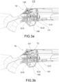
- the trigger group 10 further comprises a safety member 120 positionable in a shooting position, in which it is disengaged from the hammer device 110 which is free to move, and in a safety position, in which it engages the hammer device 110, blocking it.
- the positioning of the safety member 120 allows or inhibits the movement of the hammer device 110, in particular the movement of the hammer lever 111.
- the shot is blocked: in a preferred embodiment, by blocking the hammer device 110, the trigger 100 is also blocked; in a preferred embodiment, by locking the hammer device 110, the trigger 100 is movable when unloaded.
- the safety member 120 comprises a member lever 121 rotationally movable about a member axis O-O.
- the member axis O-O has a substantially transverse extension.
- the safety member 120 comprises a member spring 122 which engages the safety lever 121 and executes a loading action thereon.
- the member spring 122 is a torsion spring.
- the hammer lever 111 and the member lever 121 are positioned transversely, next to each other, preferably extending axially substantially parallel to each other.
- the hammer lever 111 and the member lever 121 lie substantially on two different imaginary planes which are mutually substantially parallel, preferably substantially parallel to the axis X-X.
- the hammer lever 111 and the member lever 121 have respective portions suitable for interacting.
- the interaction between the hammer lever 111 and the member lever 121 prevents the movement of the hammer lever 111.
- the hammer lever 111 comprises a cavity 115 and the member lever 121 comprises a transverse projection 125.
- the transverse projection 125 houses in the cavity 115 preventing the hammer lever 111 from moving.
- the transverse projection 125 when housed in the cavity 115, also executes a thrust action on the hammer lever 111.
- any pressure on the trigger 100 does not involve any modification of the position of the hammer lever 111.
- the trigger group 10 comprises a trigger box 11 which is removably, at least partially, housable in the receiver 6.
- Said trigger box 11 at least partially houses the aforesaid hammer device 110 and safety device 120.
- the described levers are rotationally engaged to the walls of the trigger box 11.
- the trigger box 11 is hollow and open at the top and at the bottom.
- the trigger 100 projects below.
- the trigger box 11 comprises the hand guard 118.
- the trigger box 11 is insertable into the receiver 6 through said lower opening 65.
- the trigger box 11 is insertable into the receiver 6 with an insertion movement in the vertical direction and a subsequent axial movement.
- the receiver 6 comprises trigger box sliding rails and, vice versa, the trigger box comprises protruding elements suitable for sliding on the sliding rails.
- said sliding rails have a substantially axial extension.
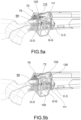
- the rifle 1 comprises a carriage assembly 3 comprising a shutter group 5.
- the shutter group 5 also comprises striker members which may be engaged by the actuated hammer device 110.
- the carriage assembly 3 comprises components, the movements and actuations of which involve a shooting action and a rearming action, i.e. discharging the exploded cartridge case to the outside and loading the bullet from the loader 500.
- the carriage assembly 3 is positioned on the receiver 6 at the upper opening 60.
- the carriage assembly 3 is positioned and has a shape suitable for closing said upper opening 60.
- the carriage assembly 3 slides on the axial edges 600 delimiting the upper opening.
- the carriage assembly 3 comprises an assembly body 30 comprising dedicated guides 300 suitable for sliding on said axial edges 600.
- the carriage assembly 3 comprises a body cover 31 mountable to the assembly body 30.
- the carriage assembly 3 is axially movable by the user between an advanced shooting configuration and a retracted rearming configuration, and vice versa.
- the carriage assembly 3 comprises a rearming handle 39, or rearming trigger, or rearming lever, which may be gripped by the user to perform the aforesaid operations.
- the shutter group 5 engages the breech element 8, completely closing the upper opening 60.
- the rifle 1 is therefore ready to execute the shooting action, acting with the trigger group 10, in particular with the hammer device 110 engaging the shutter group 5, in particular the striker members.
- the carriage assembly 3 in the retracted rearming configuration, is positioned so that the upper opening 60 is open. This means that the upper opening 60 is accessible from the top. Preferably, the upper opening 60 is accessible both from the top and from the sides.
- the rifle 1 In the retracted configuration, the rifle 1 has discharged the cartridge case, and is ready to be brought back to the advanced shooting configuration. In said movement, the carriage assembly 3 is therefore suitable for reloading a bullet which may therefore be the object of the shooting action.
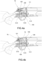
- the carriage assembly 3 further comprises a safety group 7 commandable by the user, with the carriage assembly 3 in a plurality of predefined configurations.
- the safety group 7 is suitable for being operable with the carriage assembly 3 configured in the advanced configuration.
- the safety group 7 is configurable in a ready-to-shoot configuration, in which it is disengaged from the safety member 120, and a safety configuration, in which it engages and keeps the safety member 120 in the safety position.
- the safety group 7 is operatively connected to the safety member 120 to modify the position thereof.
- the safety group 7 does not affect the possible axial movement of the entire carriage assembly 3.
- the safety group 7 is also configurable in a blocking configuration, in which it engages and keeps the safety member 120 in the safety position and in which it engages the receiver 6, preventing the movement of the carriage assembly 3, in such a way as to keep it in the advanced configuration.
- the safety group 7 is directly operatively connected to the receiver 6. In the above configuration, the safety group 7 prevents any axial movement of the entire carriage assembly 3.
- the safety group 7 comprises a safety button 70 positionable by the user between a shooting position, a safety position and, optionally, a blocking position.
- the safety button 70 is positionable by linearly translating.
- the safety button 70 is positionable in one of the above two, or three, discrete positions.
- the safety button 70 is movable in a substantially axial direction.
- the direction of movement of the safety button 70 is substantially parallel to the axial direction, inclined by a few degrees with respect to it.
- a first position of the safety button 70 is therefore the highest and most axially advanced. This position corresponds to the ready-to-shoot configuration.
- a second position of the safety button 70 is therefore not as high as the first and axially less advanced than the first. This position corresponds to the safety configuration.
- a third position of the safety button 70 is the most lowered and the most axially retracted one. This position corresponds to the blocking configuration.
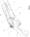
- the safety group 7 comprises an elastically yielding element 78 which acts on the safety button 70 in such a way as to keep it raised. In this way, in order to move the safety button 70 linearly, the user must overcome the elastic action of said elastically yielding element 78.
- the safety button 70 is easily operable by the user, for example by engaging it with the thumb of the hand that grips the handle of the rifle 1 with which the trigger 100 is engageable.
- the safety group 7 comprises a safety lever 72 suitable for engaging the safety member 120.
- the change in the position of the safety button 70 corresponds to a change in the position of the safety lever 72 which in turn operates on the safety member 120.
- the safety lever 72 is moved by the safety button in an axial direction.
- the safety lever 72 is moved axially by the translation of the safety button 70.
- the safety lever 72 is positioned at the lower end of the carriage assembly 3, facing the upper opening 60 of the receiver 6.
- the safety lever 72 comprises a tooth 725 protruding at the bottom: in the ready-to-shoot configuration, said tooth 725 is disengaged from the safety member 120; in the safety configuration, said tooth 725 engages and keeps the safety member 120 in the safety position, in turn blocking the movement of the hammer device 110.
- said tooth 725 engages the safety member 120 also in the blocking configuration.
- the safety lever 72 and the safety member 120 are mutually specially shaped to facilitate mutual engagement and mutual disengagement.
- the tooth 725 is suitable for sliding on a member portion 128 of the safety member 120.
- both tooth 725 and member portion 128 comprise respective inclined or arched planes.
- the member spring 122 is suitable for keeping the member lever 121 raised, disengaging the safety member 120 from the hammer device 110.
- the safety group 7 comprises a pin 79 movable between a raised position and a lowered position, in which, in the blocking configuration, the safety button 70 engages said pin 79, positioning it in the lowered position, engaging it with the receiver 6 and preventing the movement of the carriage assembly 3 on the receiver 6.
- the pin 79 is kept raised by a spring 791.
- the safety button 70 in the retracted position presses said pin 79 which then, in a lowered position, engages the receiver 6, being housed in a relevant hole 69.
- specific accessories are mountable on the breech element 8, at the upper top 80 thereof, such as for example a targeting assembly.
- the rifle which is the object of the present invention amply fulfills the intended purpose.
- the rifle which is the object of the present invention is an alternative solution to the known ones.
- the receiver has a wide and accessible upper opening.
- the carriage assembly in the retracted configuration allows wide access to the receiver.
- the carriage assembly performs axial strokes greater than the axial strokes that occur in the solutions of the prior art.
- the rifle which is the object of the present invention is suitable for carrying out shooting actions on bullets of different calibers.
- the rifle which is the object of the present invention comprises a trigger group with a hammer device benefiting from all the technical advantages of this type of actuation.
- the rifle provides specific components included in the carriage assembly and in the fixed body that are suitable for managing any dangerous situations.
- the rifle provides the possibility of inhibiting the actuation of the hammer device by operating directly on the carriage assembly.
- a simple actuation of the control button involves a change in the configuration of the state of the trigger group and/or of the entire carriage assembly.
- the interaction between the various components and kinematic mechanisms is extremely simplified and does not involve difficulties or the risk of jamming, for example in rearming operations.
- the cleaning operations of the rifle are extremely simplified.
- the disassembly and assembly of the various components in the receiver is extremely simplified.
Landscapes
- Engineering & Computer Science (AREA)
- General Engineering & Computer Science (AREA)
- Aiming, Guidance, Guns With A Light Source, Armor, Camouflage, And Targets (AREA)
- Telescopes (AREA)
Claims (14)
- Gewehr (1), umfassend:i) einen Hauptkörper (2), welcher fixiert ist, welcher einen Lauf (4), welcher sich entlang einer Achse (X-X) erstreckt, eine Aufnahmeeinheit (6), welche eine obere Öffnung (60) umfasst, welche durch axiale Kanten (600) begrenzt ist, ein Verschlusselement (8) umfasst, welches an einem axialen Ende der oberen Öffnung (60) positioniert ist;ii) eine Abzugsgruppe (10), welche wenigstens teilweise in der Aufnahmeeinheit (6) untergebracht ist, welche einen Abzug (100), eine Hammervorrichtung (110), welche durch den Abzug (100) betreibbar ist, und ein Sicherheitselement (120) umfasst, welches in einer Schussposition, in welcher es sich von der Hammervorrichtung (110) löst, und einer Sicherheitsposition positionierbar ist, in welcher es mit der Hammervorrichtung (110) eingreift, und sie blockiert;iii) eine Schlittenanordnung (3), welche einen Anordnungskörper (30) umfasst, wobei die Schlittenanordnung (3) auch eine Schließgruppe (5) umfasst, welche an der Aufnahmeeinheit (6) an der oberen Öffnung (60) positioniert ist und durch einen Nutzer axial zwischen einer vorgeschobenen Schusskonfiguration, in welcher die Schließgruppe (5) mit dem Verschlusselement (8) eingreift, und einer zurückgezogenen Nachladekonfiguration bewegbar ist, in welcher die obere Öffnung (60) offen ist, und umgekehrt, wobei die Schlittenanordnung (3) ferner eine Sicherheitsgruppe (7) umfasst, welche durch den Nutzer ansteuerbar ist, mit der Schienenanordnung (3) in der vorgeschobenen Konfiguration, in einer schussbereiten Konfiguration und einer Sicherheitskonfiguration,dadurch gekennzeichnet, dass der Anordnungskörper (30) zugehörige Führungen (300) umfasst, welche zu einem Gleiten auf den axialen Kanten (600) in der Lage sind, und darin, dass, in der schussbereiten Konfiguration, die Sicherheitsgruppe (7) von dem Sicherheitselement (120) gelöst ist und, in der Sicherheitskonfiguration, die Sicherheitsgruppe (7) mit dem Sicherheitselement (120) eingreift und dieses in der Sicherheitsposition hält.
- Gewehr (1) nach Anspruch 1, wobei die Sicherheitsgruppe (7) ferner in einer Blockierungskonfiguration einrichtbar ist, in welcher sie mit dem Sicherheitselement (120) eingreift und dieses in der Sicherheitsposition hält und in welcher sie mit der Aufnahmeeinheit (6) eingreift, welche die Bewegung der Schlittenanordnung (3) verhindert, welche sie in der vorgeschobenen Konfiguration hält.
- Gewehr (1) nach einem der vorhergehenden Ansprüche, wobei die Sicherheitsgruppe (7) einen Sicherheitsknopf (70) umfasst, welcher durch den Nutzer zwischen einer Schussposition, einer Sicherheitsposition und, optional, einer Blockierungsposition positionierbar ist.
- Gewehr (1) nach Anspruch 3, wobei der Sicherheitsknopf (70) durch lineares Verschieben positionierbar ist.
- Gewehr (1) nach einem der Ansprüche 3 oder 4, wobei die Sicherheitsgruppe (7) einen Sicherheitshebel (72) umfasst, welcher zu einem Eingreifen mit dem Sicherheitselement (120) in der Lage ist, wobei ein Wechsel in der Position des Sicherheitsknopfs (70) einem Wechsel in einer Position des Sicherheitshebels (72) entspricht, welcher wiederum auf das Sicherheitselement (120) wirkt.
- Gewehr (1) nach Anspruch 5, wobei der Sicherheitshebel (72) durch den Sicherheitsknopf in einer axialen Richtung bewegt ist.
- Gewehr (1) nach einem der Ansprüche 5 oder 6, wobei der Sicherheitshebel (72) einen Zahn (725) umfasst, welcher an dem Boden vorsteht, wobei, in der schussbereiten Konfiguration, der Zahn (725) von dem Sicherheitselement (120) gelöst ist, während er, in der Sicherheitskonfiguration, mit dem Sicherheitselement (120) eingreift und dieses in der Sicherheitsposition hält.
- Gewehr (1) nach einem der Ansprüche 3 bis 7, in Kombination mit Anspruch 2, wobei die Sicherheitsgruppe (7) einen Stift (79) umfasst, welcher zwischen einer gehobenen Position und einer abgesenkten Position bewegbar ist, in welcher, in der Blockierungsposition, der Sicherheitsknopf (70) mit dem Stift (79) eingreift, ihn in der abgesenkten Position positioniert, ihn mit der Aufnahmeeinheit (6) zu einem Eingreifen bringt und die Bewegung der Schlittenanordnung (3) an der Aufnahmeeinheit (6) verhindert.
- Gewehr (1) nach einem der vorhergehenden Ansprüche, wobei die Hammervorrichtung (110) einen Hammerhebel (111) umfasst, welcher um eine Hammerachse (C-C) rotationsbewegbar ist, welche sich im Wesentlichen transversal erstreckt, in welcher das Sicherheitselement (120) einen Elementhebel (121) umfasst, welcher um eine Elementachse (O-O) rotationsbewegbar ist, welche sich im Wesentlichen transversal erstreckt.
- Gewehr (1) nach Anspruch 9, wobei die Hammervorrichtung (110) eine Hammerfeder (112) umfasst, welche mit dem Hammerhebel (111) eingreift und eine Ladeaktion an dem Hammerhebel (111) ausführt, und das Sicherheitselement (120) eine Elementfeder (122) umfasst, welche eine Schubkraftaktion an dem Elementhebel (121) ausführt.
- Gewehr (1) nach dem Anspruch 9 oder Anspruch 10, wobei der Hammerhebel (111) und der Elementhebel (121) nebeneinander transversal positioniert sind, welche sich bevorzugt axial im Wesentlichen parallel zueinander erstrecken.
- Gewehr (1) nach einem der vorhergehenden Ansprüche, wobei der Hammerhebel (111) eine Ausnehmung (115) umfasst und der Elementhebel (121) einen transversalen Vorsprung (125) umfasst, in welchem, in der Sicherheitsposition, der transversale Vorsprung (125) in der Ausnehmung (115) untergebracht ist, was ein Bewegen des Hammerhebels (111) verhindert.
- Gewehr (1) nach einem der vorhergehenden Ansprüche, wobei die Abzugsgruppe (10) eine Abzugsbox (11) umfasst, welche wenigstens teilweise in der Aufnahmeeinheit (6) lösbar unterbringbar ist.
- Gewehr (1) nach Anspruch 13, wobei die Aufnahmeeinheit (6) eine untere Öffnung (65) umfasst, wobei das Gewehr einen Lader (500) umfasst, welcher in die untere Öffnung (65) einführbar ist, in welcher die Abzugsbox (11) in die Aufnahmeeinheit (6) durch die untere Öffnung (65) einführbar ist.
Applications Claiming Priority (1)
| Application Number | Priority Date | Filing Date | Title |
|---|---|---|---|
| IT102021000026648A IT202100026648A1 (it) | 2021-10-18 | 2021-10-18 | Fucile con gruppo sicura |
Publications (2)
| Publication Number | Publication Date |
|---|---|
| EP4166891A1 EP4166891A1 (de) | 2023-04-19 |
| EP4166891B1 true EP4166891B1 (de) | 2025-02-19 |
Family
ID=79601836
Family Applications (1)
| Application Number | Title | Priority Date | Filing Date |
|---|---|---|---|
| EP22199815.6A Active EP4166891B1 (de) | 2021-10-18 | 2022-10-05 | Gewehr mit sicherheitsgruppe |
Country Status (3)
| Country | Link |
|---|---|
| US (1) | US11933563B2 (de) |
| EP (1) | EP4166891B1 (de) |
| IT (1) | IT202100026648A1 (de) |
Cited By (1)
| Publication number | Priority date | Publication date | Assignee | Title |
|---|---|---|---|---|
| WO2026068691A1 (de) | 2024-09-27 | 2026-04-02 | AKILA d.o.o. | Geradezugrepetierer |
Family Cites Families (10)
| Publication number | Priority date | Publication date | Assignee | Title |
|---|---|---|---|---|
| US1108400A (en) * | 1913-03-27 | 1914-08-25 | Sears Roebuck & Co | Firearm. |
| US1704889A (en) * | 1926-05-21 | 1929-03-12 | Robert M Gardiner | Breech-loading safety gun |
| US3234679A (en) * | 1964-12-17 | 1966-02-15 | Mossberg & Sons O F | Thumb-operated safety for boltaction firearms |
| US3949508A (en) * | 1974-06-10 | 1976-04-13 | Emhart Corporation | Firing mechanism |
| US4024664A (en) * | 1975-10-22 | 1977-05-24 | Frank Murabito | Safety for rifle |
| DE102010055683A1 (de) * | 2010-12-22 | 2012-06-28 | Blaser Finanzholding Gmbh | Sicherung eines Repetiergewehrs |
| US9267750B1 (en) * | 2013-08-17 | 2016-02-23 | Superior Shooting Systems, Inc | Drop-in adjustable trigger assembly with camming safety linkage |
| EP3161404B1 (de) * | 2014-06-26 | 2018-10-24 | Sturm, Ruger & Company, Inc. | Sicherungsmechanismus für feuerwaffe |
| DE102018114381B4 (de) * | 2018-06-15 | 2020-12-17 | Deep GmbH | Repetiergewehr |
| DE102020104565A1 (de) * | 2020-02-20 | 2021-08-26 | Andreas Jakele | Schusswaffe |
-
2021
- 2021-10-18 IT IT102021000026648A patent/IT202100026648A1/it unknown
-
2022
- 2022-10-05 EP EP22199815.6A patent/EP4166891B1/de active Active
- 2022-10-18 US US17/968,226 patent/US11933563B2/en active Active
Cited By (1)
| Publication number | Priority date | Publication date | Assignee | Title |
|---|---|---|---|---|
| WO2026068691A1 (de) | 2024-09-27 | 2026-04-02 | AKILA d.o.o. | Geradezugrepetierer |
Also Published As
| Publication number | Publication date |
|---|---|
| IT202100026648A1 (it) | 2023-04-18 |
| US11933563B2 (en) | 2024-03-19 |
| US20230117711A1 (en) | 2023-04-20 |
| EP4166891A1 (de) | 2023-04-19 |
Similar Documents
| Publication | Publication Date | Title |
|---|---|---|
| US9494378B2 (en) | Ambidextrously operated bolt catch assembly | |
| US9714804B2 (en) | Firearm with safe axis firing pin and center aligned barrel | |
| EP3129739B1 (de) | Abzugssystem für feuerwaffen | |
| US12123667B2 (en) | Bolt catch for a firearm | |
| US20060048425A1 (en) | Forwardly-placed firearm fire control assembly | |
| US20060048430A1 (en) | Forwardly movable assembly for a firearm | |
| US11656040B2 (en) | Bolt stop with a locking device for an automatic firearm, and a grip stock and receiver equipped therewith | |
| US20170122689A1 (en) | Ambidextrous Safety for a Firearm | |
| US11473863B2 (en) | Receivers for self-loading firearms and self-loading firearms equipped with receivers | |
| EP4166895B1 (de) | Gewehr | |
| US7395747B2 (en) | Breechblock stops for firearms and methods of operating the same | |
| US20060265925A1 (en) | Locking levers for removable ammunition magazines for firearms and methods of operating the same | |
| EP4166890B1 (de) | Gewehr mit rückstossgruppe | |
| EP4166891B1 (de) | Gewehr mit sicherheitsgruppe | |
| US5992075A (en) | Repeating gun having an axially guided repeating unit | |
| EP4166894B1 (de) | Feuerwaffe mit einer eine verstelleinrichtung aufweisenden abzugsgruppe | |
| EP4166892B1 (de) | Gewehr mit verschlussgruppe | |
| EP4702306A1 (de) | Sicherheits-demontagehebel | |
| FI3931519T3 (fi) | Lippaan salvalla varustettu pistooli | |
| EP4153930B1 (de) | Schlagbolzensicherung einer schusswaffe | |
| US20250334360A1 (en) | Firearm piston and fire control mechanism | |
| EP4533019A1 (de) | Ergonomisches gewehr mit einem mechanischen halter | |
| WO2023229560A1 (en) | Ergonomic rifle with a mechanizm holder | |
| KR100590353B1 (ko) | 브리치 록을 구비한 화기 | |
| IL322705A (en) | Bullpup firearm |
Legal Events
| Date | Code | Title | Description |
|---|---|---|---|
| PUAI | Public reference made under article 153(3) epc to a published international application that has entered the european phase |
Free format text: ORIGINAL CODE: 0009012 |
|
| STAA | Information on the status of an ep patent application or granted ep patent |
Free format text: STATUS: THE APPLICATION HAS BEEN PUBLISHED |
|
| AK | Designated contracting states |
Kind code of ref document: A1 Designated state(s): AL AT BE BG CH CY CZ DE DK EE ES FI FR GB GR HR HU IE IS IT LI LT LU LV MC ME MK MT NL NO PL PT RO RS SE SI SK SM TR |
|
| P01 | Opt-out of the competence of the unified patent court (upc) registered |
Effective date: 20230522 |
|
| STAA | Information on the status of an ep patent application or granted ep patent |
Free format text: STATUS: REQUEST FOR EXAMINATION WAS MADE |
|
| 17P | Request for examination filed |
Effective date: 20231016 |
|
| RBV | Designated contracting states (corrected) |
Designated state(s): AL AT BE BG CH CY CZ DE DK EE ES FI FR GB GR HR HU IE IS IT LI LT LU LV MC ME MK MT NL NO PL PT RO RS SE SI SK SM TR |
|
| STAA | Information on the status of an ep patent application or granted ep patent |
Free format text: STATUS: EXAMINATION IS IN PROGRESS |
|
| 17Q | First examination report despatched |
Effective date: 20240212 |
|
| GRAP | Despatch of communication of intention to grant a patent |
Free format text: ORIGINAL CODE: EPIDOSNIGR1 |
|
| STAA | Information on the status of an ep patent application or granted ep patent |
Free format text: STATUS: GRANT OF PATENT IS INTENDED |
|
| INTG | Intention to grant announced |
Effective date: 20241015 |
|
| GRAS | Grant fee paid |
Free format text: ORIGINAL CODE: EPIDOSNIGR3 |
|
| GRAA | (expected) grant |
Free format text: ORIGINAL CODE: 0009210 |
|
| STAA | Information on the status of an ep patent application or granted ep patent |
Free format text: STATUS: THE PATENT HAS BEEN GRANTED |
|
| AK | Designated contracting states |
Kind code of ref document: B1 Designated state(s): AL AT BE BG CH CY CZ DE DK EE ES FI FR GB GR HR HU IE IS IT LI LT LU LV MC ME MK MT NL NO PL PT RO RS SE SI SK SM TR |
|
| REG | Reference to a national code |
Ref country code: GB Ref legal event code: FG4D |
|
| REG | Reference to a national code |
Ref country code: CH Ref legal event code: EP |
|
| REG | Reference to a national code |
Ref country code: IE Ref legal event code: FG4D |
|
| REG | Reference to a national code |
Ref country code: DE Ref legal event code: R096 Ref document number: 602022010760 Country of ref document: DE |
|
| REG | Reference to a national code |
Ref country code: SE Ref legal event code: TRGR |
|
| REG | Reference to a national code |
Ref country code: NL Ref legal event code: MP Effective date: 20250219 |
|
| PG25 | Lapsed in a contracting state [announced via postgrant information from national office to epo] |
Ref country code: RS Free format text: LAPSE BECAUSE OF FAILURE TO SUBMIT A TRANSLATION OF THE DESCRIPTION OR TO PAY THE FEE WITHIN THE PRESCRIBED TIME-LIMIT Effective date: 20250519 |
|
| PG25 | Lapsed in a contracting state [announced via postgrant information from national office to epo] |
Ref country code: FI Free format text: LAPSE BECAUSE OF FAILURE TO SUBMIT A TRANSLATION OF THE DESCRIPTION OR TO PAY THE FEE WITHIN THE PRESCRIBED TIME-LIMIT Effective date: 20250219 |
|
| PG25 | Lapsed in a contracting state [announced via postgrant information from national office to epo] |
Ref country code: PL Free format text: LAPSE BECAUSE OF FAILURE TO SUBMIT A TRANSLATION OF THE DESCRIPTION OR TO PAY THE FEE WITHIN THE PRESCRIBED TIME-LIMIT Effective date: 20250219 |
|
| PG25 | Lapsed in a contracting state [announced via postgrant information from national office to epo] |
Ref country code: ES Free format text: LAPSE BECAUSE OF FAILURE TO SUBMIT A TRANSLATION OF THE DESCRIPTION OR TO PAY THE FEE WITHIN THE PRESCRIBED TIME-LIMIT Effective date: 20250219 |
|
| REG | Reference to a national code |
Ref country code: LT Ref legal event code: MG9D |
|
| PG25 | Lapsed in a contracting state [announced via postgrant information from national office to epo] |
Ref country code: NO Free format text: LAPSE BECAUSE OF FAILURE TO SUBMIT A TRANSLATION OF THE DESCRIPTION OR TO PAY THE FEE WITHIN THE PRESCRIBED TIME-LIMIT Effective date: 20250519 Ref country code: IS Free format text: LAPSE BECAUSE OF FAILURE TO SUBMIT A TRANSLATION OF THE DESCRIPTION OR TO PAY THE FEE WITHIN THE PRESCRIBED TIME-LIMIT Effective date: 20250619 |
|
| PG25 | Lapsed in a contracting state [announced via postgrant information from national office to epo] |
Ref country code: NL Free format text: LAPSE BECAUSE OF FAILURE TO SUBMIT A TRANSLATION OF THE DESCRIPTION OR TO PAY THE FEE WITHIN THE PRESCRIBED TIME-LIMIT Effective date: 20250219 |
|
| PG25 | Lapsed in a contracting state [announced via postgrant information from national office to epo] |
Ref country code: HR Free format text: LAPSE BECAUSE OF FAILURE TO SUBMIT A TRANSLATION OF THE DESCRIPTION OR TO PAY THE FEE WITHIN THE PRESCRIBED TIME-LIMIT Effective date: 20250219 |
|
| PG25 | Lapsed in a contracting state [announced via postgrant information from national office to epo] |
Ref country code: LV Free format text: LAPSE BECAUSE OF FAILURE TO SUBMIT A TRANSLATION OF THE DESCRIPTION OR TO PAY THE FEE WITHIN THE PRESCRIBED TIME-LIMIT Effective date: 20250219 Ref country code: PT Free format text: LAPSE BECAUSE OF FAILURE TO SUBMIT A TRANSLATION OF THE DESCRIPTION OR TO PAY THE FEE WITHIN THE PRESCRIBED TIME-LIMIT Effective date: 20250620 |
|
| PG25 | Lapsed in a contracting state [announced via postgrant information from national office to epo] |
Ref country code: BG Free format text: LAPSE BECAUSE OF FAILURE TO SUBMIT A TRANSLATION OF THE DESCRIPTION OR TO PAY THE FEE WITHIN THE PRESCRIBED TIME-LIMIT Effective date: 20250219 Ref country code: GR Free format text: LAPSE BECAUSE OF FAILURE TO SUBMIT A TRANSLATION OF THE DESCRIPTION OR TO PAY THE FEE WITHIN THE PRESCRIBED TIME-LIMIT Effective date: 20250520 |
|
| REG | Reference to a national code |
Ref country code: AT Ref legal event code: MK05 Ref document number: 1768621 Country of ref document: AT Kind code of ref document: T Effective date: 20250219 |
|
| PG25 | Lapsed in a contracting state [announced via postgrant information from national office to epo] |
Ref country code: SM Free format text: LAPSE BECAUSE OF FAILURE TO SUBMIT A TRANSLATION OF THE DESCRIPTION OR TO PAY THE FEE WITHIN THE PRESCRIBED TIME-LIMIT Effective date: 20250219 |
|
| PG25 | Lapsed in a contracting state [announced via postgrant information from national office to epo] |
Ref country code: DK Free format text: LAPSE BECAUSE OF FAILURE TO SUBMIT A TRANSLATION OF THE DESCRIPTION OR TO PAY THE FEE WITHIN THE PRESCRIBED TIME-LIMIT Effective date: 20250219 |
|
| PGFP | Annual fee paid to national office [announced via postgrant information from national office to epo] |
Ref country code: TR Payment date: 20250922 Year of fee payment: 4 |
|
| PG25 | Lapsed in a contracting state [announced via postgrant information from national office to epo] |
Ref country code: AT Free format text: LAPSE BECAUSE OF FAILURE TO SUBMIT A TRANSLATION OF THE DESCRIPTION OR TO PAY THE FEE WITHIN THE PRESCRIBED TIME-LIMIT Effective date: 20250219 |
|
| PGFP | Annual fee paid to national office [announced via postgrant information from national office to epo] |
Ref country code: FR Payment date: 20250930 Year of fee payment: 4 |
|
| PG25 | Lapsed in a contracting state [announced via postgrant information from national office to epo] |
Ref country code: EE Free format text: LAPSE BECAUSE OF FAILURE TO SUBMIT A TRANSLATION OF THE DESCRIPTION OR TO PAY THE FEE WITHIN THE PRESCRIBED TIME-LIMIT Effective date: 20250219 |
|
| PG25 | Lapsed in a contracting state [announced via postgrant information from national office to epo] |
Ref country code: RO Free format text: LAPSE BECAUSE OF FAILURE TO SUBMIT A TRANSLATION OF THE DESCRIPTION OR TO PAY THE FEE WITHIN THE PRESCRIBED TIME-LIMIT Effective date: 20250219 |
|
| PG25 | Lapsed in a contracting state [announced via postgrant information from national office to epo] |
Ref country code: SK Free format text: LAPSE BECAUSE OF FAILURE TO SUBMIT A TRANSLATION OF THE DESCRIPTION OR TO PAY THE FEE WITHIN THE PRESCRIBED TIME-LIMIT Effective date: 20250219 |
|
| REG | Reference to a national code |
Ref country code: DE Ref legal event code: R097 Ref document number: 602022010760 Country of ref document: DE |
|
| PLBE | No opposition filed within time limit |
Free format text: ORIGINAL CODE: 0009261 |
|
| STAA | Information on the status of an ep patent application or granted ep patent |
Free format text: STATUS: NO OPPOSITION FILED WITHIN TIME LIMIT |
|
| PGFP | Annual fee paid to national office [announced via postgrant information from national office to epo] |
Ref country code: DE Payment date: 20251027 Year of fee payment: 4 |
|
| PGFP | Annual fee paid to national office [announced via postgrant information from national office to epo] |
Ref country code: IT Payment date: 20251031 Year of fee payment: 4 |
|
| PGFP | Annual fee paid to national office [announced via postgrant information from national office to epo] |
Ref country code: BE Payment date: 20251021 Year of fee payment: 4 |
|
| PGFP | Annual fee paid to national office [announced via postgrant information from national office to epo] |
Ref country code: SE Payment date: 20251022 Year of fee payment: 4 |
|
| PGFP | Annual fee paid to national office [announced via postgrant information from national office to epo] |
Ref country code: CZ Payment date: 20250930 Year of fee payment: 4 |
|
| 26N | No opposition filed |
Effective date: 20251120 |