EP4166785B1 - Integrierte luftzufuhreinheit - Google Patents
Integrierte luftzufuhreinheit Download PDFInfo
- Publication number
- EP4166785B1 EP4166785B1 EP22201150.4A EP22201150A EP4166785B1 EP 4166785 B1 EP4166785 B1 EP 4166785B1 EP 22201150 A EP22201150 A EP 22201150A EP 4166785 B1 EP4166785 B1 EP 4166785B1
- Authority
- EP
- European Patent Office
- Prior art keywords
- bore
- passage
- piston
- valve
- supply unit
- Prior art date
- Legal status (The legal status is an assumption and is not a legal conclusion. Google has not performed a legal analysis and makes no representation as to the accuracy of the status listed.)
- Active
Links
Images


Classifications
-
- F—MECHANICAL ENGINEERING; LIGHTING; HEATING; WEAPONS; BLASTING
- F04—POSITIVE - DISPLACEMENT MACHINES FOR LIQUIDS; PUMPS FOR LIQUIDS OR ELASTIC FLUIDS
- F04B—POSITIVE-DISPLACEMENT MACHINES FOR LIQUIDS; PUMPS
- F04B39/00—Component parts, details, or accessories, of pumps or pumping systems specially adapted for elastic fluids, not otherwise provided for in, or of interest apart from, groups F04B25/00 - F04B37/00
- F04B39/16—Filtration; Moisture separation
-
- F—MECHANICAL ENGINEERING; LIGHTING; HEATING; WEAPONS; BLASTING
- F04—POSITIVE - DISPLACEMENT MACHINES FOR LIQUIDS; PUMPS FOR LIQUIDS OR ELASTIC FLUIDS
- F04B—POSITIVE-DISPLACEMENT MACHINES FOR LIQUIDS; PUMPS
- F04B35/00—Piston pumps specially adapted for elastic fluids and characterised by the driving means to their working members, or by combination with, or adaptation to, specific driving engines or motors, not otherwise provided for
- F04B35/04—Piston pumps specially adapted for elastic fluids and characterised by the driving means to their working members, or by combination with, or adaptation to, specific driving engines or motors, not otherwise provided for the means being electric
-
- F—MECHANICAL ENGINEERING; LIGHTING; HEATING; WEAPONS; BLASTING
- F04—POSITIVE - DISPLACEMENT MACHINES FOR LIQUIDS; PUMPS FOR LIQUIDS OR ELASTIC FLUIDS
- F04B—POSITIVE-DISPLACEMENT MACHINES FOR LIQUIDS; PUMPS
- F04B39/00—Component parts, details, or accessories, of pumps or pumping systems specially adapted for elastic fluids, not otherwise provided for in, or of interest apart from, groups F04B25/00 - F04B37/00
- F04B39/08—Actuation of distribution members
-
- F—MECHANICAL ENGINEERING; LIGHTING; HEATING; WEAPONS; BLASTING
- F04—POSITIVE - DISPLACEMENT MACHINES FOR LIQUIDS; PUMPS FOR LIQUIDS OR ELASTIC FLUIDS
- F04B—POSITIVE-DISPLACEMENT MACHINES FOR LIQUIDS; PUMPS
- F04B39/00—Component parts, details, or accessories, of pumps or pumping systems specially adapted for elastic fluids, not otherwise provided for in, or of interest apart from, groups F04B25/00 - F04B37/00
- F04B39/10—Adaptations or arrangements of distribution members
-
- F—MECHANICAL ENGINEERING; LIGHTING; HEATING; WEAPONS; BLASTING
- F04—POSITIVE - DISPLACEMENT MACHINES FOR LIQUIDS; PUMPS FOR LIQUIDS OR ELASTIC FLUIDS
- F04B—POSITIVE-DISPLACEMENT MACHINES FOR LIQUIDS; PUMPS
- F04B39/00—Component parts, details, or accessories, of pumps or pumping systems specially adapted for elastic fluids, not otherwise provided for in, or of interest apart from, groups F04B25/00 - F04B37/00
- F04B39/12—Casings; Cylinders; Cylinder heads; Fluid connections
- F04B39/121—Casings
-
- F—MECHANICAL ENGINEERING; LIGHTING; HEATING; WEAPONS; BLASTING
- F04—POSITIVE - DISPLACEMENT MACHINES FOR LIQUIDS; PUMPS FOR LIQUIDS OR ELASTIC FLUIDS
- F04B—POSITIVE-DISPLACEMENT MACHINES FOR LIQUIDS; PUMPS
- F04B39/00—Component parts, details, or accessories, of pumps or pumping systems specially adapted for elastic fluids, not otherwise provided for in, or of interest apart from, groups F04B25/00 - F04B37/00
- F04B39/12—Casings; Cylinders; Cylinder heads; Fluid connections
- F04B39/123—Fluid connections
-
- F—MECHANICAL ENGINEERING; LIGHTING; HEATING; WEAPONS; BLASTING
- F04—POSITIVE - DISPLACEMENT MACHINES FOR LIQUIDS; PUMPS FOR LIQUIDS OR ELASTIC FLUIDS
- F04B—POSITIVE-DISPLACEMENT MACHINES FOR LIQUIDS; PUMPS
- F04B41/00—Pumping installations or systems specially adapted for elastic fluids
- F04B41/02—Pumping installations or systems specially adapted for elastic fluids having reservoirs
-
- F—MECHANICAL ENGINEERING; LIGHTING; HEATING; WEAPONS; BLASTING
- F04—POSITIVE - DISPLACEMENT MACHINES FOR LIQUIDS; PUMPS FOR LIQUIDS OR ELASTIC FLUIDS
- F04B—POSITIVE-DISPLACEMENT MACHINES FOR LIQUIDS; PUMPS
- F04B49/00—Control, e.g. of pump delivery, or pump pressure of, or safety measures for, machines, pumps, or pumping installations, not otherwise provided for, or of interest apart from, groups F04B1/00 - F04B47/00
- F04B49/22—Control, e.g. of pump delivery, or pump pressure of, or safety measures for, machines, pumps, or pumping installations, not otherwise provided for, or of interest apart from, groups F04B1/00 - F04B47/00 by means of valves
-
- F—MECHANICAL ENGINEERING; LIGHTING; HEATING; WEAPONS; BLASTING
- F04—POSITIVE - DISPLACEMENT MACHINES FOR LIQUIDS; PUMPS FOR LIQUIDS OR ELASTIC FLUIDS
- F04B—POSITIVE-DISPLACEMENT MACHINES FOR LIQUIDS; PUMPS
- F04B7/00—Piston machines or pumps characterised by having positively-driven valving
- F04B7/0073—Piston machines or pumps characterised by having positively-driven valving the member being of the lost-motion type, e.g. friction-actuated members, or having means for pushing it against or pulling it from its seat
Definitions
- the present disclosure relates generally to air supply units for vehicles, such as automobiles. More specifically, the present disclosure relates to an integrated air supply unit for operating an air-lift suspension in a vehicle.
- Air suspension assemblies are known in the art for use on various vehicles, including automobiles. Air suspension assemblies typically include a plurality of air springs, each for interconnecting the body and one of the wheels of the automotive vehicle for damping relative forces between the body and the wheels, and for adjusting the height of the automotive vehicle.
- Air suspension assemblies typically include a plurality of air springs, each for interconnecting the body and one of the wheels of the automotive vehicle for damping relative forces between the body and the wheels, and for adjusting the height of the automotive vehicle.
- One example of such an air suspension assembly is disclosed in U.S. Pat. No. 5,465,209 to Sammut et al.
- the air suspension assembly includes a compressor for filling the air springs as well as a plurality of valves that are disposed between the compressor and the air springs and controlled by a controller for regulating airflow from the compressor to the air springs.
- An air suspension assembly may include an air supply unit (ASU) that combines a compressor and dryer with an exhaust control valve.
- a separate Integrated Air Management Module (IAMM) may include control valves, a manifold pressure sensor, and a ECU in a single unit.
- the IAMM may communicate with the ASU through a pressure port, a boost port, and through one or more electrical connections.
- Document CN205744338U discloses a two rank pressure boost air compressor machine including a cylinder body and a motor, the motor drives piston reciprocating motion in the cylinder body, by air inlet intake air, and by the gas vent exhaust air.
- the machine includes air inlets, compression end air vents, check valves, exhaust solenoid valves and desiccators.
- the present invention provides an integrated air supply unit as claimed in the appended claims.
- the integrated air supply unit comprises a compressor housing that includes a piston slidably disposed within a piston bore.
- the integrated air supply unit also comprises a pressure control unit (PCU) body defining a plurality of fluid passages and a plurality of solenoid valves configured to selectively control airflow through corresponding ones of the plurality of fluid passages.
- PCU pressure control unit
- the integrated air supply unit also comprises a desiccant housing extending between the compressor housing and the PCU body and defining a desiccant cavity configured to hold a desiccant container for removing moisture from air passing therethrough.
- the integrated air supply unit further comprises: a manifold including at least one fluid passage; a discharge control valve configured to selectively control airflow from the manifold to a supply port for supplying pressurized air to an external device; a compressor configured to supply pressurized air in a first pressurized air passage, wherein the compressor comprises the compressor housing; a dryer configured to remove moisture from the pressurized air in the first pressurized air passage and to supply dried pressurized air in a second pressurized air passage, wherein the dryer comprises the desiccant housing; and a supply control valve configured to configured to selectively control airflow between the second pressurized air passage and the manifold.
- the integrated air supply unit also comprises a piloted exhaust valve.
- the piloted exhaust valve includes an inlet passage and a discharge passage and is configured to control airflow therebetween.
- the piloted exhaust valve includes an exhaust valve bore having a semi-closed end, a tubular portion extending from the semi-closed end and into the exhaust valve bore, and a stepped piston that slidably movable within the exhaust valve bore.
- the stepped piston divides the exhaust valve bore between a first chamber and a second chamber.
- the stepped piston includes a control surface defining an end of the first chamber, and a lower surface opposite the control surface.
- the stepped piston also includes a piston extension that extends into the tubular portion.
- the piston extension includes a sealing face configured to selectively seal against a valve seat to block fluid communication between the inlet passage and the discharge passage.
- the integrated air supply unit also comprises an exhaust control valve configured to selectively control flow of air between the first chamber and the second chamber of the piloted exhaust valve.
- the inlet passage of the piloted exhaust valve is in direct fluid communication with the
- the present disclosure also provides an integrated air supply unit that comprises: a manifold including at least one fluid passage; a discharge control valve configured to selectively control airflow from the manifold to a supply port for supplying pressurized air to an external device; a compressor configured to supply pressurized air in a first pressurized air passage; a dryer configured to remove moisture from the pressurized air in the first pressurized air passage and to supply dried pressurized air in a second pressurized air passage; and a supply control valve configured to configured to selectively control airflow between the second pressurized air passage and the manifold.
- the integrated air supply unit also comprises a piloted exhaust valve.
- the piloted exhaust valve includes an inlet passage and a discharge passage and is configured to control airflow therebetween.
- the piloted exhaust valve includes an exhaust valve bore having a semi-closed end, a tubular portion extending from the semi-closed end and into the exhaust valve bore, and a stepped piston that slidably movable within the exhaust valve bore.
- the stepped piston divides the exhaust valve bore between a first chamber and a second chamber.
- the stepped piston includes a control surface defining an end of the first chamber, and a lower surface opposite the control surface.
- the stepped piston also includes a piston extension that extends into the tubular portion.
- the piston extension includes a sealing face configured to selectively seal against a valve seat to block fluid communication between the inlet passage and the discharge passage.
- the integrated air supply unit also comprises an exhaust control valve configured to selectively control flow of air between the first chamber and the second chamber of the piloted exhaust valve.
- the first chamber of the piloted exhaust valve is in direct fluid communication with the second pressurized air passage.
- the second chamber of the piloted exhaust valve is direct in fluid communication with an exhaust passage open to atmosphere.
- the inlet passage of the piloted exhaust valve is in direct fluid communication with the first pressurized air passage.
- the present disclosure also provides an air pump.
- the air pump comprises a compressor housing and a sliding member.
- the compressor housing defines a stepped bore including a low-pressure bore having a first cross-sectional area and a high-pressure bore coaxial with the low-pressure bore and having a second cross-sectional area smaller than the first cross-sectional area.
- the sliding member includes a low-pressure piston slidably disposed in the low-pressure bore and a high-pressure piston slidably disposed in the high-pressure bore.
- the sliding member defines a hollow cavity between the low-pressure piston and the high-pressure piston.
- the air pump also includes articulating member disposed within the hollow cavity of the sliding member and pivotably coupled thereto by a wrist pin.
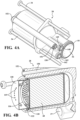
- Figs. 1A-1C show various views of an Integrated Air Supply Unit (IASU) 20, which may be installed in a vehicle for operating an air-lift suspension in the vehicle.
- the IASU 20of the present disclosure may combine a compressor, dryer, exhaust control valves, and an Integrated Air Management Module (IAMM) in an integrated assembly.
- IAMM Integrated Air Management Module
- the IASU 20 of the present disclosure may be more compact and have a lower weight than conventional air supply units.
- the IASU 20 includes a mounting bracket 22 to which the remaining components are attached.
- the mounting bracket 22 may include a foundation, such as a baseplate, and mounting structures, such as tabs, flanges, holes, etc. for attachment to one or more vehicle structures.
- the mounting bracket 22 may be customized for a particular vehicular application, whereas other components of the IASU 20 may be standardized.
- the IASU 20 also includes a compressor housing 24, a pressure control unit (PCU) body 26, a desiccant housing 28, a motor assembly 30, an electronic control unit (ECU) 32, an exhaust muffler 38, and an air intake hose 46.
- PCU pressure control unit
- ECU electronice control unit
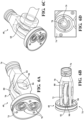
- Fig. 2 shows an exploded view of the IASU 20, including tie-rod bolts 34 that join the compressor housing 24, the desiccant housing 28, the motor assembly 30, and the PCU body 26.
- Three isolation mounts 36 are attached to the mounting bracket 22 for holding corresponding ones of the compressor housing 24 and the PCU body 26, while preventing vibrations from being transmitted from the compressor housing 24 to the mounting bracket 22. It should be appreciated that this is merely an example configuration, and the mounting bracket 22 may have a different size or shape, and the IASU 20 may include any number of the isolation mounts 36 in any configuration.
- Fig. 2 also shows an exhaust muffler 38 attached to the compressor housing 24, and a dual piston assembly 40 that fits within a stepped bore 42 of the compressor housing 24.
- the stepped bore 42 is enclosed by a low-pressure chamber cover 44 that overlies a corresponding face of the compressor housing 24 and is attached thereto with screws.
- An intake hose barb 48 screws into the compressor housing 24 for fluidly coupling to the air intake hose 46.
- a service cap 50 screws into a corresponding port (not shown in Fig. 2 ) in the compressor housing 24 to provide access to the stepped bore 42.
- the PCU body 26 may include a block of material, such as machined aluminum, defining a plurality of fluid passages (not shown on Fig. 2 ).
- the PCU body 26 may include a plurality of solenoid bores 25, each receiving a corresponding valve core 27.
- the valve cores 27 may each cooperate with corresponding fluid passages to form solenoid valves that are configured to selectively control airflow through the corresponding fluid passages.
- the PCU body 26 also defines a plurality of air ports 29 providing fluid communication to transmit air to/from external devices, such as air springs and/or an external air reservoir.
- a piloted exhaust valve 52 is coupled to the PCU body 26 and fits within a corresponding exhaust valve bore 54 of the desiccant housing 28.
- the compressor housing 24 defines a motor bore 56 for receiving the motor assembly 30.
- the compressor housing 24 also defines a desiccant bore 58 for receiving the desiccant housing 28.
- Each of the motor bore 56 and the desiccant bore 58 are defined in a common face of the compressor housing 24 adjacent to one another and each extend perpendicular to the stepped bore 42.
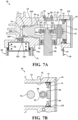
- the motor assembly 30 includes a motor shaft 60 having a main shaft bearing 62 disposed thereabout, and an eccentric bearing 64 located on an end thereof.
- a power connector 66 extends out of an end of the motor assembly 30 opposite from the eccentric bearing 64 and extents through a corresponding hole in the PCU body 26 to plug into the ECU 32.
- Figs. 3A-3B show additional details of the compressor housing 24, including various integrally formed cooling fins, and showing attachment of the intake hose barb 48 and the service cap 50.
- Fig. 3B shows the compressor housing 24 as partially transparent to illustrate internal components including a low-pressure outlet check valve LOCV and a high-pressure outlet check valve HOCV that are integrated therein.
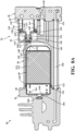
- Figs. 4A-4C show various views of the desiccant housing 28, including radial O-ring seals 55, 149, 151, 163 for sealing the exhaust valve bore 54 and the passageways 148, 150, 162, respectively, on a common face of the PCU body 26.
- a desiccant container 68 containing desiccant material and filters is disposed within the desiccant housing 28.
- the desiccant housing 28 defines a through-bore 150, which extends between and fluidly connects the compressor housing 24 and the PCU body 26.
- the through-bore 150 may also be called a boost passageway.
- the desiccant housing 28 also defines an exhaust passage 37 for conveying exhaust air to the exhaust muffler 38.
- a compressor-side radial O-ring seal 152 is shown on Fig. 4B for sealing the through-bore 150 of the desiccant housing 28 to the compressor housing 24.
- Fig. 5 shows details of the pressure control unit (PCU) body 26, including the solenoid bores 25 and the plurality of air ports 29 all disposed on a common face of the PCU body 26.
- PCU pressure control unit
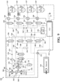
- Fig. 9 shows a schematic diagram of a first arrangement 320 of the IASU 20.
- the first arrangement 320 includes four supply ports 322, 324, 326, 328, including a left-front supply port 322, a right-front supply port 324, a left-rear supply port 326, and a right-rear supply port 328.
- Each of the supply ports 322, 324, 326, 328 is fluidly coupled to supply air to a corresponding air spring 323, 325, 327, 329, including a left-front air spring 323, a right-front air spring 325, a left-rear air spring 327, and a right-rear air spring 329.
- Fig. 10 shows a schematic diagram of a second arrangement 420 of the IASU 20.
- the second arrangement 420 for the IASU 20 may be similar or identical to the first arrangement 320 of the IASU 20, shown in Fig. 9 , with a few changes described herein.
Landscapes
- Engineering & Computer Science (AREA)
- Mechanical Engineering (AREA)
- General Engineering & Computer Science (AREA)
- Compressors, Vaccum Pumps And Other Relevant Systems (AREA)
- Compressor (AREA)
- Fluid-Pressure Circuits (AREA)
- Drying Of Gases (AREA)
Claims (15)
- Eine integrierte Luftversorgungseinheit (20), die aus Folgendem besteht:einem Kompressorgehäuse (24) mit einem in einer Kolbenbohrung gleitend angeordneten Kolben;einem Körper der Drucksteuereinheit (PCU-Körper) (26), der eine Vielzahl von Flüssigkeitskanälen und eine Vielzahl von Magnetventilen definiert, die so konfiguriert sind, dass sie den Luftstrom durch entsprechende Kanäle der Vielzahl von Flüssigkeitskanälen selektiv steuern; undeinem Trockenmittelgehäuse (28), das sich zwischen dem Kompressorgehäuse (24) und dem PCU-Körper (26) erstreckt und eine Trockenmittelkammer (110) definiert, der so konfiguriert ist, dass er einen Trockenmittelbehälter (68) zum Entfernen von Feuchtigkeit aus der durch ihn hindurchströmenden Luft aufnimmt,wobei die integrierte Luftversorgungseinheit (20) weiterhin aus Folgendem besteht:einem Verteiler (338) mit mindestens einem Flüssigkeitskanal;einem Abflusssteuerventil (330, 332, 334, 336), das so konfiguriert ist, dass es den Luftstrom vom Verteiler (338) zu einem Versorgungsanschluss (322, 324, 326, 328) für die Zufuhr von Druckluft zu einer externen Vorrichtung selektiv steuert; einem Kompressor (360), der so konfiguriert ist, dass er Druckluft in einen ersten Druckluftdurchgang (370) liefert, wobei der Kompressor (360) das Kompressorgehäuse (24) umfasst;einem Trockner (372), der so konfiguriert ist, dass er Feuchtigkeit aus der Druckluft in dem ersten Druckluftdurchgang (370) entfernt und getrocknete Druckluft in einen zweiten Druckluftdurchgang (374) liefert, wobei der Trockner (372) das Trockenmittelgehäuse (28) umfasst;einem Versorgungssteuerventil (376), das so konfiguriert ist, dass es den Luftstrom zwischen dem zweiten Druckluftdurchgang (374) und dem Verteiler (338) selektiv steuert;einem gesteuerten Auslassventil (52), das einen Einlasskanal (131) und einen Auslasskanal (132) enthält und so konfiguriert ist, dass es den Luftstrom dazwischen steuert, wobei das gesteuerte Auslassventil (52) eine Auslassventilbohrung (54) mit einem halbgeschlossenen Ende (53), einen rohrförmigen Abschnitt (139), der sich von dem halbgeschlossenen Ende (53) und in die Auslassventilbohrung (54) erstreckt, und einen Stufenkolben (134) enthält, der in der Auslassventilbohrung (54) gleitend beweglich ist und die Auslassventilbohrung (54) in eine erste Kammer (146) und eine zweite Kammer (147) unterteilt, wobei der Stufenkolben (134) eine Steuerfläche (136), die ein Ende der ersten Kammer (146) definiert, und eine untere Fläche (137) gegenüber der Steuerfläche (136) aufweist, wobei der Stufenkolben (134) eine Kolbenverlängerung (138) aufweist, die sich in den rohrförmigen Abschnitt (139) erstreckt, wobei die Kolbenverlängerung (138) eine Dichtungsfläche (140) aufweist, die so konfiguriert ist, dass sie selektiv gegen einen Ventilsitz (141) abdichtet, um eine Flüssigkeitsverbindung zwischen dem Einlasskanal (131) und dem Auslasskanal (132) zu blockieren; undeinem Auslasssteuerventil (396), das so konfiguriert ist, dass es selektiv den Luftstrom zwischen der ersten Kammer (146) und der zweiten Kammer (147) des gesteuerten Auslassventils (52) steuert,wobei der Einlasskanal (131) des gesteuerten Auslassventils (52) in direkter Flüssigkeitsverbindung mit dem ersten Druckluftdurchgang (370) steht.
- Die integrierte Luftversorgungseinheit (20) nach Anspruch 1, wobei das Trockenmittelgehäuse (28) eine Durchgangsbohrung (150) definiert, die sich zwischen dem Kompressorgehäuse (24) und dem PCU-Körper (26) erstreckt und durch radiale Dichtungen an jedem Ende davon abgedichtet ist.
- Die integrierte Luftversorgungseinheit (20) nach Anspruch 1 oder 2, wobei das Trockenmittelgehäuse (28) ferner ein Führungsloch (170) definiert, das so konfiguriert ist, dass es einen großen Bolzen (34) führt, der das Kompressorgehäuse (24) und den PCU-Körper (26) verbindet.
- Die integrierte Luftversorgungseinheit (20) nach einem der Ansprüche 1 bis 3, wobei das Kompressorgehäuse (24) einen Flüssigkeitskanal zwischen der Kolbenbohrung und der Trockenmittelkammer (110) definiert; und
wobei die integrierte Luftversorgungseinheit (20) ferner ein Rückschlagventil (100) umfasst, das ein elastomeres Element (101) enthält, das gegen das Kompressorgehäuse (24) vorgespannt ist, um den Flüssigkeitskanal zwischen der Kolbenbohrung und der Trockenmittelkammer (110) selektiv zu blockieren und einen Luftstrom von der Kolbenbohrung in die Trockenmittelkammer (110) zuzulassen, während der Luftstrom in einer entgegengesetzten Richtung blockiert wird. - Die integrierte Luftversorgungseinheit (20) nach Anspruch 1, die ferner aus Folgendem besteht:
einem weiteren Abgassteuerventil (394), das so konfiguriert ist, dass es den Strom von Druckluft aus dem zweiten Druckluftdurchgang (374) zur ersten Kammer (146) des gesteuerten Abgasventils (52) selektiv steuert. - Die integrierte Luftversorgungseinheit (20) nach Anspruch 5, wobei der Kompressor (360) ferner aus Folgendem besteht:einem Elektromotor (362),wobei der in der Kolbenbohrung angeordnete Kolben von dem Elektromotor (362) angetrieben wird und so konfiguriert ist, dass er Druckluft in den ersten Druckluftdurchgang (370) einspeist.
- Die integrierte Luftversorgungseinheit (20) nach Anspruch 5 oder 6, die ferner aus Folgendem besteht:einem Reservoiranschluss (312), der eine Flüssigkeitsverbindung zu einem externen Reservoir (310) herstellt; undmindestens einem Reservoirventil (350, 352), das so konfiguriert ist, dass es selektiv eine Flüssigkeitsverbindung zwischen dem Reservoiranschluss (312) und dem Verteiler (338) herstellt, wobei das mindestens eine Reservoirventil (350, 352) zwei Reservoirventile (350, 352) in einer parallelen Konfiguration und mit unterschiedlichen Durchflusseigenschaften umfasst.
- Die integrierte Luftversorgungseinheit (20) nach Anspruch 1, wobei die erste Kammer (146) des gesteuerten Auslassventils (52) in direkter Flüssigkeitsverbindung mit dem zweiten Druckluftdurchgang (374) steht; und
wobei die zweite Kammer (147) des gesteuerten Auslassventils (52) direkt in Flüssigkeitsverbindung mit einem zur Atmosphäre offenen Auslasskanal steht. - Die integrierte Luftversorgungseinheit (20) nach Anspruch 8 oder 5, wobei der Trockenmittelhohlraum ein Trockenmittelmaterial enthält; und wobei das Trockenmittelmaterial in einem Luftströmungsweg zwischen dem ersten Druckluftdurchgang (370) und dem zweiten Druckluftdurchgang (374) angeordnet ist, um Feuchtigkeit aus der dazwischen durchströmenden Luft zu entfernen.
- Die integrierte Luftversorgungseinheit (20) nach Anspruch 8, die ferner aus Folgendem besteht:einem ersten Rückschlagventil (430), das in dem zweiten Druckluftdurchgang (374) angeordnet und so konfiguriert ist, dass es einen Luftstrom von dem Verteiler (338) zu dem Trockner (372) zulässt, während es den Luftstrom in einer entgegengesetzten Richtung blockiert; undeinem Umgehungsdurchgang (432), der eine Flüssigkeitsverbindung zwischen dem Verteiler (338) und dem zweiten Druckluftdurchgang (374) herstellt, mit einem zweiten Rückschlagventil (434), das in dem Umgehungsdurchgang (432) angeordnet und so konfiguriert ist, dass es einen Luftstrom von dem zweiten Druckluftdurchgang (374) zu dem Verteiler (338) zulässt, während es den Luftstrom in einer entgegengesetzten Richtung blockiert.
- Die integrierte Luftversorgungseinheit (20) nach Anspruch 8, die ferner aus Folgendem besteht:einem Reservoiranschluss (312), der eine Flüssigkeitsverbindung zu einem externen Reservoir herstellt; undmindestens einem Reservoirventil (350, 352), das so konfiguriert ist, dass es selektiv eine Flüssigkeitsverbindung zwischen dem Reservoiranschluss (312) und dem Verteiler (338) herstellt.
- Die integrierte Luftversorgungseinheit (20) nach Anspruch 11 oder 7, die ferner aus Folgendem besteht:
einem Verstärkungsventil (380), das so konfiguriert ist, dass es selektiv eine Flüssigkeitsverbindung zwischen dem Reservoiranschluss (312) und einem Einlass des Kompressors (360) herstellt. - Die integrierte Luftversorgungseinheit (20) nach Anspruch 1, wobei die Kolbenbohrung eine Stufenbohrung (42) ist, die eine Niederdruckbohrung (42l) mit einer ersten Querschnittsfläche und eine zur Niederdruckbohrung (42l) koaxiale Hochdruckbohrung (42h) mit einer zweiten Querschnittsfläche kleiner als die erste Querschnittsfläche aufweist;wobei die integrierte Luftversorgungseinheit (20) ferner ein Gleitelement (70) umfasst, das einen Niederdruckkolben (74), der gleitend in der Niederdruckbohrung (42l) angeordnet ist, und einen Hochdruckkolben (76), der gleitend in der Hochdruckbohrung (42h) angeordnet ist, enthält, wobei der Kolben den Niederdruckkolben (74) und den Hochdruckkolben (76) enthält, wobei das Gleitelement (70) einen Hohlraum zwischen dem Niederdruckkolben (74) und dem Hochdruckkolben (76) definiert; undein Gelenkelement (80), das in dem Hohlraum (72) des Gleitelements (70) angeordnet und durch einen Gelenkstift (90) schwenkbar mit diesem verbunden ist.
- Die integrierte Luftversorgungseinheit (20) nach Anspruch 13 besteht ferner aus Folgendem:einer Motorbaugruppe (30) mit einem Motorgehäuse und einer Motorwelle (60), die um eine Achse drehbar ist und mit einer exzentrischen Welle (64) gekoppelt ist, die von der Achse versetzt ist; undein Lager (64), das in dem hohlen Hohlraum (72) des Gleitelements (70) angeordnet ist und zwischen dem Gelenkelement (80) und um die exzentrische Welle (64) herum angeordnet ist und bewirkt, dass das Gelenkelement (80) als Reaktion auf die sich um die Achse drehende Motorwelle (60) eine oszillierende lineare Bewegung durch die Stufenbohrung (42) überträgt; und/oder wobei das Kompressorgehäuse (24) eine Motorbohrung (56) definiert, die sich quer zu der Stufenbohrung (42) erstreckt und so konfiguriert ist, dass sie die Motorwelle (60) aufnimmt, und wobei das Kompressorgehäuse (24) einen Vorsprung (96) definiert, der sich nach außen um mindestens einen Teil eines Umfangs der Motorbohrung (56) erstreckt, um mit dem Motorgehäuse in Eingriff zu kommen.
- Die integrierte Luftversorgungseinheit (20) nach Anspruch 13 oder 14, die ferner aus Folgendem besteht:einem Durchgang (98), der sich durch den Niederdruckkolben (74) erstreckt; undeinem Flatterventil (78), das den Durchgang (98) abdeckt und einen Luftstrom in einer Richtung durchlässt, während es den Luftstrom in einer entgegengesetzten Richtung blockiert, wobei das Flatterventil (78) insbesondere an einer Fläche des Niederdruckkolbens (74) durch ein Befestigungselement, einen Klebstoff oder durch Schweißen befestigt ist.
Applications Claiming Priority (2)
| Application Number | Priority Date | Filing Date | Title |
|---|---|---|---|
| US17/501,049 US11813916B2 (en) | 2021-10-14 | 2021-10-14 | Integrated air supply unit |
| CN202211114687.2A CN115479214B (zh) | 2021-10-14 | 2022-09-14 | 集成空气供应单元和空气泵 |
Publications (3)
| Publication Number | Publication Date |
|---|---|
| EP4166785A2 EP4166785A2 (de) | 2023-04-19 |
| EP4166785A3 EP4166785A3 (de) | 2023-06-07 |
| EP4166785B1 true EP4166785B1 (de) | 2025-03-26 |
Family
ID=83691187
Family Applications (1)
| Application Number | Title | Priority Date | Filing Date |
|---|---|---|---|
| EP22201150.4A Active EP4166785B1 (de) | 2021-10-14 | 2022-10-12 | Integrierte luftzufuhreinheit |
Country Status (3)
| Country | Link |
|---|---|
| EP (1) | EP4166785B1 (de) |
| ES (1) | ES3024997T3 (de) |
| PL (1) | PL4166785T3 (de) |
Family Cites Families (5)
| Publication number | Priority date | Publication date | Assignee | Title |
|---|---|---|---|---|
| US5465209A (en) | 1994-06-10 | 1995-11-07 | General Motors Corporation | Vehicle level control system |
| DE102011117106A1 (de) * | 2011-10-27 | 2013-05-02 | Knorr-Bremse Systeme für Schienenfahrzeuge GmbH | Kondensatabscheidereinrichtung für eine Kompressoranordnung zur Erzeugung von Druckluft |
| DE102015219613A1 (de) * | 2015-10-09 | 2017-04-13 | Continental Teves Ag & Co. Ohg | Integrierte Luftversorgungseinheit mit Lufttrockner und Luftfedersystem, sowie Steuerung einer Luftversorgungseinheit |
| CN106089630B (zh) * | 2016-06-14 | 2018-07-20 | 浙江瑞翔机电科技股份有限公司 | 一种双阶增压空压机 |
| CN205744338U (zh) * | 2016-06-14 | 2016-11-30 | 浙江瑞翔机电科技股份有限公司 | 一种双阶增压空压机 |
-
2022
- 2022-10-12 ES ES22201150T patent/ES3024997T3/es active Active
- 2022-10-12 PL PL22201150.4T patent/PL4166785T3/pl unknown
- 2022-10-12 EP EP22201150.4A patent/EP4166785B1/de active Active
Also Published As
| Publication number | Publication date |
|---|---|
| ES3024997T3 (en) | 2025-06-05 |
| PL4166785T3 (pl) | 2025-06-09 |
| EP4166785A2 (de) | 2023-04-19 |
| EP4166785A3 (de) | 2023-06-07 |
Similar Documents
| Publication | Publication Date | Title |
|---|---|---|
| US11813916B2 (en) | Integrated air supply unit | |
| EP1839982B1 (de) | Hydraulikdrucksteuergerät für Fahrzeugbremsen | |
| US5213482A (en) | Hydraulic radial-type piston pump | |
| US5600953A (en) | Compressed air control apparatus | |
| US5096400A (en) | Hydraulic pump | |
| KR0153769B1 (ko) | 차량 브레이크 장치용 유압식 고압펌프 | |
| JPH0133670B2 (de) | ||
| JPH08113129A (ja) | ブレーキ圧調整装置 | |
| CN101284528B (zh) | 用于电子控制制动系统的泵 | |
| EP4166785B1 (de) | Integrierte luftzufuhreinheit | |
| JP3347597B2 (ja) | 車両用懸架装置 | |
| US6231321B1 (en) | Air compressor | |
| US8925440B2 (en) | Hydraulic module including a pump housing with surface-connected pump elements | |
| EP1653080B1 (de) | Auslasskanal eines Verdichters mit Rückschlagventil | |
| JPH076496B2 (ja) | 真空ポンプにおける吸引系切換装置 | |
| US6109385A (en) | Hydrostatic unit for driving an industrial truck | |
| US6446668B2 (en) | Multiway valve | |
| US20030021709A1 (en) | Plunger pump device | |
| WO2020204132A1 (ja) | 容量制御弁 | |
| KR20050114736A (ko) | 레이디얼 피스톤 펌프 | |
| EP0597610B1 (de) | Flüssigkeitsdruck-Quelle für Flüssigkeitsbetätigten Verstärker | |
| US4990065A (en) | Plunger pump | |
| US7857336B1 (en) | Air suspension system | |
| KR100329158B1 (ko) | 압축기의 기동쇼크 완화장치 | |
| JP2603432B2 (ja) | マルチステージ真空ポンプ |
Legal Events
| Date | Code | Title | Description |
|---|---|---|---|
| PUAI | Public reference made under article 153(3) epc to a published international application that has entered the european phase |
Free format text: ORIGINAL CODE: 0009012 |
|
| STAA | Information on the status of an ep patent application or granted ep patent |
Free format text: STATUS: THE APPLICATION HAS BEEN PUBLISHED |
|
| AK | Designated contracting states |
Kind code of ref document: A2 Designated state(s): AL AT BE BG CH CY CZ DE DK EE ES FI FR GB GR HR HU IE IS IT LI LT LU LV MC ME MK MT NL NO PL PT RO RS SE SI SK SM TR |
|
| PUAL | Search report despatched |
Free format text: ORIGINAL CODE: 0009013 |
|
| AK | Designated contracting states |
Kind code of ref document: A3 Designated state(s): AL AT BE BG CH CY CZ DE DK EE ES FI FR GB GR HR HU IE IS IT LI LT LU LV MC ME MK MT NL NO PL PT RO RS SE SI SK SM TR |
|
| RIC1 | Information provided on ipc code assigned before grant |
Ipc: F04B 39/12 20060101ALI20230503BHEP Ipc: F04B 49/22 20060101ALI20230503BHEP Ipc: F04B 39/16 20060101ALI20230503BHEP Ipc: F04B 39/10 20060101ALI20230503BHEP Ipc: F04B 39/08 20060101ALI20230503BHEP Ipc: F04B 7/00 20060101AFI20230503BHEP |
|
| STAA | Information on the status of an ep patent application or granted ep patent |
Free format text: STATUS: REQUEST FOR EXAMINATION WAS MADE |
|
| 17P | Request for examination filed |
Effective date: 20231207 |
|
| RBV | Designated contracting states (corrected) |
Designated state(s): AL AT BE BG CH CY CZ DE DK EE ES FI FR GB GR HR HU IE IS IT LI LT LU LV MC ME MK MT NL NO PL PT RO RS SE SI SK SM TR |
|
| GRAP | Despatch of communication of intention to grant a patent |
Free format text: ORIGINAL CODE: EPIDOSNIGR1 |
|
| STAA | Information on the status of an ep patent application or granted ep patent |
Free format text: STATUS: GRANT OF PATENT IS INTENDED |
|
| INTG | Intention to grant announced |
Effective date: 20241016 |
|
| GRAS | Grant fee paid |
Free format text: ORIGINAL CODE: EPIDOSNIGR3 |
|
| GRAA | (expected) grant |
Free format text: ORIGINAL CODE: 0009210 |
|
| STAA | Information on the status of an ep patent application or granted ep patent |
Free format text: STATUS: THE PATENT HAS BEEN GRANTED |
|
| AK | Designated contracting states |
Kind code of ref document: B1 Designated state(s): AL AT BE BG CH CY CZ DE DK EE ES FI FR GB GR HR HU IE IS IT LI LT LU LV MC ME MK MT NL NO PL PT RO RS SE SI SK SM TR |
|
| REG | Reference to a national code |
Ref country code: GB Ref legal event code: FG4D |
|
| REG | Reference to a national code |
Ref country code: CH Ref legal event code: EP |
|
| P01 | Opt-out of the competence of the unified patent court (upc) registered |
Free format text: CASE NUMBER: APP_11686/2025 Effective date: 20250311 |
|
| REG | Reference to a national code |
Ref country code: DE Ref legal event code: R096 Ref document number: 602022012206 Country of ref document: DE |
|
| REG | Reference to a national code |
Ref country code: IE Ref legal event code: FG4D |
|
| REG | Reference to a national code |
Ref country code: ES Ref legal event code: FG2A Ref document number: 3024997 Country of ref document: ES Kind code of ref document: T3 Effective date: 20250605 |
|
| PG25 | Lapsed in a contracting state [announced via postgrant information from national office to epo] |
Ref country code: RS Free format text: LAPSE BECAUSE OF FAILURE TO SUBMIT A TRANSLATION OF THE DESCRIPTION OR TO PAY THE FEE WITHIN THE PRESCRIBED TIME-LIMIT Effective date: 20250626 |
|
| PG25 | Lapsed in a contracting state [announced via postgrant information from national office to epo] |
Ref country code: FI Free format text: LAPSE BECAUSE OF FAILURE TO SUBMIT A TRANSLATION OF THE DESCRIPTION OR TO PAY THE FEE WITHIN THE PRESCRIBED TIME-LIMIT Effective date: 20250326 |
|
| REG | Reference to a national code |
Ref country code: LT Ref legal event code: MG9D |
|
| PG25 | Lapsed in a contracting state [announced via postgrant information from national office to epo] |
Ref country code: NO Free format text: LAPSE BECAUSE OF FAILURE TO SUBMIT A TRANSLATION OF THE DESCRIPTION OR TO PAY THE FEE WITHIN THE PRESCRIBED TIME-LIMIT Effective date: 20250626 |
|
| PG25 | Lapsed in a contracting state [announced via postgrant information from national office to epo] |
Ref country code: HR Free format text: LAPSE BECAUSE OF FAILURE TO SUBMIT A TRANSLATION OF THE DESCRIPTION OR TO PAY THE FEE WITHIN THE PRESCRIBED TIME-LIMIT Effective date: 20250326 |
|
| PG25 | Lapsed in a contracting state [announced via postgrant information from national office to epo] |
Ref country code: LV Free format text: LAPSE BECAUSE OF FAILURE TO SUBMIT A TRANSLATION OF THE DESCRIPTION OR TO PAY THE FEE WITHIN THE PRESCRIBED TIME-LIMIT Effective date: 20250326 |
|
| PG25 | Lapsed in a contracting state [announced via postgrant information from national office to epo] |
Ref country code: GR Free format text: LAPSE BECAUSE OF FAILURE TO SUBMIT A TRANSLATION OF THE DESCRIPTION OR TO PAY THE FEE WITHIN THE PRESCRIBED TIME-LIMIT Effective date: 20250627 Ref country code: BG Free format text: LAPSE BECAUSE OF FAILURE TO SUBMIT A TRANSLATION OF THE DESCRIPTION OR TO PAY THE FEE WITHIN THE PRESCRIBED TIME-LIMIT Effective date: 20250326 |
|
| REG | Reference to a national code |
Ref country code: NL Ref legal event code: MP Effective date: 20250326 |
|
| PG25 | Lapsed in a contracting state [announced via postgrant information from national office to epo] |
Ref country code: NL Free format text: LAPSE BECAUSE OF FAILURE TO SUBMIT A TRANSLATION OF THE DESCRIPTION OR TO PAY THE FEE WITHIN THE PRESCRIBED TIME-LIMIT Effective date: 20250326 |
|
| PG25 | Lapsed in a contracting state [announced via postgrant information from national office to epo] |
Ref country code: SE Free format text: LAPSE BECAUSE OF FAILURE TO SUBMIT A TRANSLATION OF THE DESCRIPTION OR TO PAY THE FEE WITHIN THE PRESCRIBED TIME-LIMIT Effective date: 20250326 |
|
| REG | Reference to a national code |
Ref country code: AT Ref legal event code: MK05 Ref document number: 1779204 Country of ref document: AT Kind code of ref document: T Effective date: 20250326 |
|
| PG25 | Lapsed in a contracting state [announced via postgrant information from national office to epo] |
Ref country code: SM Free format text: LAPSE BECAUSE OF FAILURE TO SUBMIT A TRANSLATION OF THE DESCRIPTION OR TO PAY THE FEE WITHIN THE PRESCRIBED TIME-LIMIT Effective date: 20250326 |
|
| PG25 | Lapsed in a contracting state [announced via postgrant information from national office to epo] |
Ref country code: PT Free format text: LAPSE BECAUSE OF FAILURE TO SUBMIT A TRANSLATION OF THE DESCRIPTION OR TO PAY THE FEE WITHIN THE PRESCRIBED TIME-LIMIT Effective date: 20250728 |
|
| PGFP | Annual fee paid to national office [announced via postgrant information from national office to epo] |
Ref country code: PL Payment date: 20250904 Year of fee payment: 4 |
|
| PG25 | Lapsed in a contracting state [announced via postgrant information from national office to epo] |
Ref country code: AT Free format text: LAPSE BECAUSE OF FAILURE TO SUBMIT A TRANSLATION OF THE DESCRIPTION OR TO PAY THE FEE WITHIN THE PRESCRIBED TIME-LIMIT Effective date: 20250326 |
|
| PGFP | Annual fee paid to national office [announced via postgrant information from national office to epo] |
Ref country code: FR Payment date: 20250908 Year of fee payment: 4 |
|
| PG25 | Lapsed in a contracting state [announced via postgrant information from national office to epo] |
Ref country code: EE Free format text: LAPSE BECAUSE OF FAILURE TO SUBMIT A TRANSLATION OF THE DESCRIPTION OR TO PAY THE FEE WITHIN THE PRESCRIBED TIME-LIMIT Effective date: 20250326 |
|
| PGFP | Annual fee paid to national office [announced via postgrant information from national office to epo] |
Ref country code: CZ Payment date: 20250923 Year of fee payment: 4 |
|
| PGFP | Annual fee paid to national office [announced via postgrant information from national office to epo] |
Ref country code: RO Payment date: 20250922 Year of fee payment: 4 |
|
| PG25 | Lapsed in a contracting state [announced via postgrant information from national office to epo] |
Ref country code: SK Free format text: LAPSE BECAUSE OF FAILURE TO SUBMIT A TRANSLATION OF THE DESCRIPTION OR TO PAY THE FEE WITHIN THE PRESCRIBED TIME-LIMIT Effective date: 20250326 |
|
| PG25 | Lapsed in a contracting state [announced via postgrant information from national office to epo] |
Ref country code: IS Free format text: LAPSE BECAUSE OF FAILURE TO SUBMIT A TRANSLATION OF THE DESCRIPTION OR TO PAY THE FEE WITHIN THE PRESCRIBED TIME-LIMIT Effective date: 20250726 |
|
| REG | Reference to a national code |
Ref country code: DE Ref legal event code: R097 Ref document number: 602022012206 Country of ref document: DE |
|
| PGFP | Annual fee paid to national office [announced via postgrant information from national office to epo] |
Ref country code: DE Payment date: 20250902 Year of fee payment: 4 |
|
| PG25 | Lapsed in a contracting state [announced via postgrant information from national office to epo] |
Ref country code: DK Free format text: LAPSE BECAUSE OF FAILURE TO SUBMIT A TRANSLATION OF THE DESCRIPTION OR TO PAY THE FEE WITHIN THE PRESCRIBED TIME-LIMIT Effective date: 20250326 |
|
| PGFP | Annual fee paid to national office [announced via postgrant information from national office to epo] |
Ref country code: IT Payment date: 20251031 Year of fee payment: 4 |
|
| PGFP | Annual fee paid to national office [announced via postgrant information from national office to epo] |
Ref country code: ES Payment date: 20251107 Year of fee payment: 4 |
|
| PLBE | No opposition filed within time limit |
Free format text: ORIGINAL CODE: 0009261 |
|
| STAA | Information on the status of an ep patent application or granted ep patent |
Free format text: STATUS: NO OPPOSITION FILED WITHIN TIME LIMIT |
|
| REG | Reference to a national code |
Ref country code: CH Ref legal event code: L10 Free format text: ST27 STATUS EVENT CODE: U-0-0-L10-L00 (AS PROVIDED BY THE NATIONAL OFFICE) Effective date: 20260211 |
|
| 26N | No opposition filed |
Effective date: 20260105 |