EP4166765B1 - Wärmeenergieerzeugungssystem und verfahren zur steuerung davon - Google Patents
Wärmeenergieerzeugungssystem und verfahren zur steuerung davon Download PDFInfo
- Publication number
- EP4166765B1 EP4166765B1 EP21826079.2A EP21826079A EP4166765B1 EP 4166765 B1 EP4166765 B1 EP 4166765B1 EP 21826079 A EP21826079 A EP 21826079A EP 4166765 B1 EP4166765 B1 EP 4166765B1
- Authority
- EP
- European Patent Office
- Prior art keywords
- power generation
- flow path
- thermoelectric
- generation system
- temperature fluid
- Prior art date
- Legal status (The legal status is an assumption and is not a legal conclusion. Google has not performed a legal analysis and makes no representation as to the accuracy of the status listed.)
- Active
Links
Images




Classifications
-
- H—ELECTRICITY
- H10—SEMICONDUCTOR DEVICES; ELECTRIC SOLID-STATE DEVICES NOT OTHERWISE PROVIDED FOR
- H10N—ELECTRIC SOLID-STATE DEVICES NOT OTHERWISE PROVIDED FOR
- H10N10/00—Thermoelectric devices comprising a junction of dissimilar materials, i.e. devices exhibiting Seebeck or Peltier effects
- H10N10/10—Thermoelectric devices comprising a junction of dissimilar materials, i.e. devices exhibiting Seebeck or Peltier effects operating with only the Peltier or Seebeck effects
- H10N10/17—Thermoelectric devices comprising a junction of dissimilar materials, i.e. devices exhibiting Seebeck or Peltier effects operating with only the Peltier or Seebeck effects characterised by the structure or configuration of the cell or thermocouple forming the device
-
- F—MECHANICAL ENGINEERING; LIGHTING; HEATING; WEAPONS; BLASTING
- F01—MACHINES OR ENGINES IN GENERAL; ENGINE PLANTS IN GENERAL; STEAM ENGINES
- F01N—GAS-FLOW SILENCERS OR EXHAUST APPARATUS FOR MACHINES OR ENGINES IN GENERAL; GAS-FLOW SILENCERS OR EXHAUST APPARATUS FOR INTERNAL-COMBUSTION ENGINES
- F01N3/00—Exhaust or silencing apparatus having means for purifying, rendering innocuous, or otherwise treating exhaust
- F01N3/08—Exhaust or silencing apparatus having means for purifying, rendering innocuous, or otherwise treating exhaust for rendering innocuous
- F01N3/10—Exhaust or silencing apparatus having means for purifying, rendering innocuous, or otherwise treating exhaust for rendering innocuous by thermal or catalytic conversion of noxious components of exhaust
- F01N3/18—Exhaust or silencing apparatus having means for purifying, rendering innocuous, or otherwise treating exhaust for rendering innocuous by thermal or catalytic conversion of noxious components of exhaust characterised by methods of operation; Control
- F01N3/20—Exhaust or silencing apparatus having means for purifying, rendering innocuous, or otherwise treating exhaust for rendering innocuous by thermal or catalytic conversion of noxious components of exhaust characterised by methods of operation; Control specially adapted for catalytic conversion
- F01N3/2006—Periodically heating or cooling catalytic reactors, e.g. at cold starting or overheating
-
- F—MECHANICAL ENGINEERING; LIGHTING; HEATING; WEAPONS; BLASTING
- F01—MACHINES OR ENGINES IN GENERAL; ENGINE PLANTS IN GENERAL; STEAM ENGINES
- F01N—GAS-FLOW SILENCERS OR EXHAUST APPARATUS FOR MACHINES OR ENGINES IN GENERAL; GAS-FLOW SILENCERS OR EXHAUST APPARATUS FOR INTERNAL-COMBUSTION ENGINES
- F01N5/00—Exhaust or silencing apparatus combined or associated with devices profiting by exhaust energy
- F01N5/02—Exhaust or silencing apparatus combined or associated with devices profiting by exhaust energy the devices using heat
- F01N5/025—Exhaust or silencing apparatus combined or associated with devices profiting by exhaust energy the devices using heat the device being thermoelectric generators
-
- F—MECHANICAL ENGINEERING; LIGHTING; HEATING; WEAPONS; BLASTING
- F02—COMBUSTION ENGINES; HOT-GAS OR COMBUSTION-PRODUCT ENGINE PLANTS
- F02G—HOT GAS OR COMBUSTION-PRODUCT POSITIVE-DISPLACEMENT ENGINE PLANTS; USE OF WASTE HEAT OF COMBUSTION ENGINES; NOT OTHERWISE PROVIDED FOR
- F02G5/00—Profiting from waste heat of combustion engines, not otherwise provided for
- F02G5/02—Profiting from waste heat of exhaust gases
-
- H—ELECTRICITY
- H10—SEMICONDUCTOR DEVICES; ELECTRIC SOLID-STATE DEVICES NOT OTHERWISE PROVIDED FOR
- H10N—ELECTRIC SOLID-STATE DEVICES NOT OTHERWISE PROVIDED FOR
- H10N10/00—Thermoelectric devices comprising a junction of dissimilar materials, i.e. devices exhibiting Seebeck or Peltier effects
- H10N10/10—Thermoelectric devices comprising a junction of dissimilar materials, i.e. devices exhibiting Seebeck or Peltier effects operating with only the Peltier or Seebeck effects
- H10N10/13—Thermoelectric devices comprising a junction of dissimilar materials, i.e. devices exhibiting Seebeck or Peltier effects operating with only the Peltier or Seebeck effects characterised by the heat-exchanging means at the junction
-
- F—MECHANICAL ENGINEERING; LIGHTING; HEATING; WEAPONS; BLASTING
- F01—MACHINES OR ENGINES IN GENERAL; ENGINE PLANTS IN GENERAL; STEAM ENGINES
- F01N—GAS-FLOW SILENCERS OR EXHAUST APPARATUS FOR MACHINES OR ENGINES IN GENERAL; GAS-FLOW SILENCERS OR EXHAUST APPARATUS FOR INTERNAL-COMBUSTION ENGINES
- F01N2510/00—Surface coverings
- F01N2510/06—Surface coverings for exhaust purification, e.g. catalytic reaction
- F01N2510/065—Surface coverings for exhaust purification, e.g. catalytic reaction for reducing soot ignition temperature
-
- F—MECHANICAL ENGINEERING; LIGHTING; HEATING; WEAPONS; BLASTING
- F01—MACHINES OR ENGINES IN GENERAL; ENGINE PLANTS IN GENERAL; STEAM ENGINES
- F01N—GAS-FLOW SILENCERS OR EXHAUST APPARATUS FOR MACHINES OR ENGINES IN GENERAL; GAS-FLOW SILENCERS OR EXHAUST APPARATUS FOR INTERNAL-COMBUSTION ENGINES
- F01N2900/00—Details of electrical control or of the monitoring of the exhaust gas treating apparatus
- F01N2900/06—Parameters used for exhaust control or diagnosing
- F01N2900/14—Parameters used for exhaust control or diagnosing said parameters being related to the exhaust gas
- F01N2900/1404—Exhaust gas temperature
-
- Y—GENERAL TAGGING OF NEW TECHNOLOGICAL DEVELOPMENTS; GENERAL TAGGING OF CROSS-SECTIONAL TECHNOLOGIES SPANNING OVER SEVERAL SECTIONS OF THE IPC; TECHNICAL SUBJECTS COVERED BY FORMER USPC CROSS-REFERENCE ART COLLECTIONS [XRACs] AND DIGESTS
- Y02—TECHNOLOGIES OR APPLICATIONS FOR MITIGATION OR ADAPTATION AGAINST CLIMATE CHANGE
- Y02T—CLIMATE CHANGE MITIGATION TECHNOLOGIES RELATED TO TRANSPORTATION
- Y02T10/00—Road transport of goods or passengers
- Y02T10/10—Internal combustion engine [ICE] based vehicles
- Y02T10/12—Improving ICE efficiencies
Definitions
- thermoelectric power generation system that converts heat into electric power and a control method therefor.
- thermoelectric conversion element is a type of thermoelectric element that can convert heat into electric power, electric power into heat, or both heat into electric power and electric power into heat.
- a thermoelectric conversion element is composed of, for example, a thermoelectric material exhibiting the Seebeck effect. In this case, the thermoelectric conversion element can convert a temperature difference between a heat source and a heat sink into electric power and is also called a thermoelectric generator.
- thermoelectric conversion element By using such a thermoelectric conversion element, thermal energy that would have otherwise been released into the ambient environment without being used (for example, thermal energy from, for example, steam, heated water, or exhaust gas) can be collected and used efficiently.
- thermal energy from, for example, steam, heated water, or exhaust gas for example, thermal energy from, for example, steam, heated water, or exhaust gas
- PTL 1 there is disclosed an exhaust system that collects heat of exhaust gas from an engine and generates electric power.
- PTL 2 describes a vehicle system including a vehicle component, a battery, and a thermoelectric module coupled to the component to allow heat transfer between the catalytic converter and the thermoelectric module, wherein the thermoelectric module is electrically connected to the battery.
- the vehicle system further includes a temperature sensor coupled to the vehicle component. The temperature sensor is configured to measure the temperature of the vehicle component.
- the vehicle system further includes a controller in electronic communication with the thermoelectric module. The controller is programmed to switch the thermoelectric module among the heating mode, the cooling mode, and the power-generation mode based on the temperature of the vehicle component.
- the vehicle component may be an exhaust manifold, a turbocharger turbine housing, an exhaust gas conduit coupled between an exhaust manifold and a catalytic converter, and/or a catalytic converter.
- thermoelectric power generation efficiency decreases with use.
- thermoelectric power generation system that can suppress a reduction in thermoelectric power generation efficiency that occurs with use and a control method therefor.
- thermoelectric power generation system includes a first flow path along which a first fluid flows, a second flow path along which a second fluid having a lower temperature than the first fluid flows, a thermoelectric module arranged between the first flow path and the second flow path, and a controller that switches between a power generation mode, in which the thermoelectric module is caused to generate electric power based on a difference between a temperature of the first fluid and a temperature of the second fluid, and a heating mode, in which a first surface of the thermoelectric module is heated using the Peltier effect caused by supplying electric power to the thermoelectric module.
- a distance between the first surface and the first flow path is shorter than a distance between the first surface and the second flow path.
- a control method control method is a control method for a thermoelectric power generation system.
- the power generation system includes a first flow path along which a first fluid flows, a second flow path along which a second fluid having a lower temperature than the first fluid flows, and a thermoelectric module arranged between the first flow path and the second flow path, a distance between a first surface of the thermoelectric module and the first flow path being shorter than a distance between the first surface and the second flow path.
- the control method includes a step for causing the thermoelectric module to generate electric power, based on a difference between a temperature of the first fluid and a temperature of the second fluid, and a step for heating the first surface using the Peltier effect caused by supplying electric power to the thermoelectric module.
- thermoelectric power generation efficiency that occurs with use can be suppressed.
- Further advantages and effects according to an aspect of the present disclosure will be clear from the specification and the drawings. Such advantages, effects, or both the advantages and effects are each provided by characteristics described in some embodiments as well as the specification and the drawings; however, all of the embodiments, the specification, and the drawings do not always have to be provided to obtain one or more of the characteristics.
- thermoelectric conversion element can convert a temperature difference into electric power using the Seebeck effect.
- the present inventor found that a material contained in a high temperature fluid used as a heat source adheres from the high temperature fluid to a heat transfer surface of a thermoelectric conversion element, and the material adhered to the heat transfer surface reduces thermoelectric power generation efficiency.
- thermoelectric power generation system that can suppress a reduction in thermoelectric power generation efficiency that occurs with use by eliminating the material adhered to the heat transfer surface and a control method therefor.
- a first gas discharged from an internal combustion engine (hereinafter referred to as exhaust gas) is used as a high temperature fluid.
- ICE internal combustion engine
- Fig. 1 is a block diagram illustrating a functional configuration of the vehicle or ship 1 equipped with the thermoelectric power generation system 10 according to the first embodiment.
- Vehicles are conveyances that have one or more wheels and travel on land. Ships are conveyances that sail on water. As illustrated in Fig. 1 , the vehicle or ship 1 includes the thermoelectric power generation system 10, an internal combustion engine 20, an accumulator 30, a load 40, and a power generator 50.
- the internal combustion engine 20 is a motor that obtains mechanical energy using gas generated by burning fuel and is also simply called an engine. Exhaust gas from the internal combustion engine 20 contains soot produced by incomplete fuel combustion.
- thermoelectric power generation system 10 generates electric power using exhaust gas from the internal combustion engine 20. Details of the thermoelectric power generation system 10 will be described later.
- the accumulator 30 stores electric power generated by a thermoelectric power generation unit 100, the power generator 50, or both the thermoelectric power generation unit 100 and the power generator 50 and supplies electric power to the thermoelectric power generation unit 100, the load 40, or both the thermoelectric power generation unit 100 and the load 40.
- a thermoelectric power generation unit 100 for example, an accumulator battery (a secondary battery), a capacitor, or the like can be used.
- the load 40 consumes electric power generated by the thermoelectric power generation system 10, electric power stored in the accumulator 30, or electric power generated by the power generator 50.
- the load 40 for example, an electric motor used to start an air conditioner, a headlight, or the internal combustion engine 20, an electric motor used to drive or sail the vehicle or ship 1, or the like can be used.
- the power generator 50 converts mechanical energy generated by the internal combustion engine 20 into electrical energy.
- an electric motor can be used, which can also be shared with the load 40.
- an alternator, a dynamo, or the like can also be used.
- thermoelectric power generation system 10 includes the thermoelectric power generation unit 100, a controller 200, a first valve 300, and a second valve 400.
- the thermoelectric power generation unit 100 converts a temperature difference between a high temperature fluid and a low temperature fluid into electric power.
- the high temperature fluid corresponds to a first fluid
- the low temperature fluid corresponds to a second fluid having a lower temperature than the first fluid.
- Exhaust gas from the internal combustion engine 20 flows as the high temperature fluid into the thermoelectric power generation unit 100 and passes through the thermoelectric power generation unit 100.
- the low temperature fluid flows into and passes through the thermoelectric power generation unit 100.
- the controller 200 switches between a power generation mode and a heating mode.
- the controller 200 is realized by, for example, an integrated circuit.
- the controller 200 may also be realized by a processor and a memory. In this case, when an instruction or a software program stored in the memory is executed, the processor functions as the controller 200.
- the power generation mode is a mode in which a thermoelectric module is caused to generate electric power using the temperature difference between the high temperature fluid and the low temperature fluid.
- electric power is converted from the temperature difference between the high temperature fluid and the low temperature fluid by using the Seebeck effect, and the controller 200 causes the accumulator 30 to store the electric power or causes the load 40 to consume the electric power.
- the heating mode is a mode in which a first surface of the thermoelectric module is heated, the first surface being connected to a high temperature fluid flow path.
- the controller 200 supplies electric power from the accumulator 30 or the power generator 50 to the thermoelectric power generation unit 100 and consequently heats up the first surface of the thermoelectric module connected to the high temperature fluid flow path by using the Peltier effect or a synergistic effect created by the Peltier effect and the Joule heating effect caused by energization.
- Member A is connected to member B may refer to a case where member A is directly connected to member B or a case where member A is indirectly connected to member B.
- “Member A is directly connected to member B” may refer to a case where there is no other member between member A and member B.
- “Member A is indirectly connected to member B” may refer to a case where there is one or more members between member A and member B.
- the first valve 300 is an example of a first flow rate control means, and is a flow rate control valve that controls the inflow rate of air into the thermoelectric power generation unit 100.
- the first valve 300 is controlled by the controller 200. For example, by controlling the first valve 300, the controller 200 increases the inflow rate of air in the heating mode in comparison with the inflow rate in the power generation mode.
- air is an example of a second gas, and is a gas having a higher oxygen concentration than exhaust gas.
- air can promote combustion of soot adhered to the thermoelectric power generation unit 100.
- the second gas is not limited to air, and any gas may be used as long as the gas has a higher oxygen concentration than exhaust gas and does not prevent soot from burning.
- the second valve 400 is an example of a second flow rate control means, and is a flow rate control valve that controls the inflow rate of the low temperature fluid into the thermoelectric power generation unit 100.
- the second valve 400 is controlled by the controller 200.
- the controller 200 controls the second valve 400 in accordance with the temperature of the low temperature fluid flowing out from the thermoelectric power generation unit 100.
- the controller 200 increases the inflow rate of the low temperature fluid in a case where the temperature of the low temperature fluid is greater than or equal to a first predetermined threshold temperature, for example, by controlling the second valve 400.
- the controller 200 may reduce the inflow rate of the low temperature fluid in a case where the temperature of the low temperature fluid is less than a second predetermined threshold temperature.
- the first predetermined threshold temperature and the second predetermined threshold temperature may be equal to each other or different from each other.
- temperatures predetermined empirically, experimentally, or empirically and experimentally can be used as the first predetermined threshold temperature and the second predetermined threshold temperature.
- the temperature of the low temperature fluid can be acquired by, for example, a temperature sensor arranged at a low temperature fluid outlet of the thermoelectric power generation unit 100.
- first flow rate control means and the second flow rate control means are not limited to valves.
- a fan and a pump can be used as the first flow rate control means, the second flow rate control means, or both the first flow rate control means and the second flow rate control means.
- the thermoelectric power generation system 10 does not have to include the first flow rate control means, the second flow rate control means, or both the first flow rate control means and the second flow rate control means.
- thermoelectric power generation unit 100 included in the thermoelectric power generation system 10
- Fig. 2 is a perspective view of the thermoelectric power generation unit 100 according to the first embodiment.
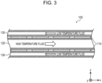
- Fig. 3 is a cross sectional view of the thermoelectric power generation unit 100 according to the first embodiment.
- the cross section of the thermoelectric power generation unit 100 in Fig. 3 corresponds to the cross section taken along line iii-iii in Fig. 2 .
- the thermoelectric power generation unit 100 includes a thermoelectric module 110, a high temperature fluid flow path 120, and a low temperature fluid flow path 130.
- Fig. 2 illustrates two thermoelectric modules 110 and two low temperature fluid flow paths 130.
- the number of thermoelectric modules 110 may be one.
- the number of low temperature fluid flow paths 130 may be one.
- thermoelectric modules 110 have a flat plate like shape, and are each disposed between the high temperature fluid flow path 120 and a corresponding one of the low temperature fluid flow paths 130. By being arranged in this manner, a temperature difference occurs in the thickness direction of the thermoelectric module 110 (the z axis direction). The detailed configuration of the thermoelectric module 110 will be described later using Fig. 4 .
- the high temperature fluid flow path 120 is an example of a first flow path along which the high temperature fluid flows, and is arranged so as to be connected to the first surface of the thermoelectric module 110.
- the high temperature fluid flow path 120 is thermally connected to the first surface.
- thermoelectric power generation unit 100 decreases.
- thermoelectric power generation efficiency of the thermoelectric power generation unit 100 is restored.
- a catalyst for promoting combustion of soot may be applied onto the inner surface of the high temperature fluid flow path 120.
- the catalyst for example, precious metal, transition metal oxides, or the like can be used.
- the low temperature fluid flow path 130 is an example of a second flow path along which the low temperature fluid flows, and is arranged so as to be connected to a second surface of the thermoelectric module 110.
- the low temperature fluid flow path 130 is thermally connected to the second surface.
- the low temperature fluid for example, water, air, or the like can be used; however, the low temperature fluid is not limited thereto.
- the inner structures of the high temperature fluid flow path 120 and the low temperature fluid flow path 130 are not particularly limited.
- fins may be provided in the high temperature fluid flow path 120 and the low temperature fluid flow path 130 to improve heat transfer performance.
- the shapes of the fins for example, a plate shape, a pin shape, a comb shape, or the like can be used.
- thermoelectric module 110 included in the thermoelectric power generation unit 100
- Fig. 4 is a perspective view of the thermoelectric module 110 according to the first embodiment.
- the thermoelectric module 110 includes thermoelectric conversion elements 111 and two electric insulating plates 117.
- the two electric insulating plates 117 form a surface 110a of the thermoelectric module 110 and a surface 110b on the opposite side to the surface 110a.
- the surface 110a is an example of the first surface, and is connected to the high temperature fluid flow path 120.
- the surface 110b is an example of the second surface, and is connected to the low temperature fluid flow path 130.
- the electric insulating plates 117 for example, ceramic plates can be used; however, the electric insulating plates 117 are not limited thereto.
- thermoelectric conversion elements 111 includes two different types of thermoelectric materials 112 and 113 and electrodes 114a to 114c.
- thermoelectric materials 112 and 113 for example, a p-type semiconductor and an n-type semiconductor can be used, in which the electrical polarities of the carriers are different from each other. Note that the thermoelectric materials 112 and 113 are not limited to a p-type semiconductor and an n-type semiconductor.
- thermoelectric materials 112 and 113 are each connected to an end of a thermoelectric material of a different type or a lead 115 or 116.
- the top ends of the thermoelectric materials 112 and 113 are connected to each other via the electrode 114a.
- the bottom end of the thermoelectric material 112 is connected via the electrode 114c to the bottom end of the thermoelectric material 113 included in an adjacent thermoelectric conversion element 111.
- the bottom end of the thermoelectric material 113 is connected via the electrode 114b to the lead 115.
- the structure of the thermoelectric module 110, in which the thermoelectric conversion elements 111 are connected in this manner, is called a ⁇ type structure. In the ⁇ type structure, two different types of thermoelectric materials are electrically connected in series and thermally connected in parallel.
- thermoelectric module 110 configured in this manner can convert, using the Seebeck effect, a temperature difference between the high temperature fluid flowing along the flow path connected to the surface 110a and the low temperature fluid flowing along the flow path connected to the surface 110b into electrical power.
- the thermoelectric module 110 supplies electric power via the leads 115 and 116.
- the thermoelectric module 110 can absorb heat through the surface 110b and discharge heat through the surface 110a using the Peltier effect. Furthermore, the thermoelectric module 110 can generate heat using the Joule heating effect caused by energization. As a result, the surface 110a is heated. In this case, the thermoelectric module 110 consumes electric power received via the leads 115 and 116.
- Fig. 5 is a flow chart illustrating processing performed by the controller 200 of the thermoelectric power generation system 10 according to the first embodiment. That is, Fig. 5 illustrates a method for controlling the thermoelectric power generation system 10.
- the controller 200 selects a mode (S101). Specifically, the controller 200 selects one out of the power generation mode and the heating mode. That is, the controller 200 switches between the power generation mode and the heating mode.
- the controller 200 may select the mode on the basis of the driving load of the internal combustion engine 20. Specifically, the controller 200 may select the power generation mode in a case where the driving load of the internal combustion engine 20 is high and may select the heating mode in a case where the driving load of the internal combustion engine 20 is low. In a case where the driving load of the internal combustion engine 20 is high, the temperature of exhaust gas is high, and the amount of discharged exhaust gas is large. Thus, a greater amount of electric power can be efficiently generated by selecting the power generation mode. In a case where the driving load of the internal combustion engine 20 is low, it is likely that a large amount of regenerative power is generated by the power generator 50. Thus, by selecting the heating mode, regenerative power can be effectively used, and the energy efficiency of the entire vehicle or ship 1 can be improved.
- the controller 200 may select the mode on the basis of at least one of the position information, congestion information, surroundings image information, or driving information about the vehicle or ship 1.
- the position information indicates the position of the vehicle or ship 1 and can be acquired through, for example, a global positioning system (GPS).
- the congestion information indicates the level of vehicle or ship congestion around the vehicle or ship 1 and can be acquired from, for example, traffic information distributed using radio waves, light, or the like.
- the surroundings image information is images of the surroundings of the vehicle or ship 1 and can be acquired using a camera installed in or on the vehicle or ship 1.
- the driving information is information regarding driving of the vehicle or ship 1 and indicates, for example, a speed, a steering angle, or operation of the wiper.
- the driving information can be acquired using a sensor installed in or on the vehicle or ship 1.
- the controller 200 may select the heating mode in a case where the position information indicates the position of a downward slope. It is likely that the driving load of the internal combustion engine 20 decreases, and a large amount of regenerative power is obtained, and thus the controller 200 may select the heating mode. In contrast, in a case where the position information indicates the position of an upward slope, the controller 200 may select the power generation mode. For example, in a case where the congestion information, the surroundings image information, or both the congestion information and the surroundings image information indicate congestion, it is likely that the driving load of the internal combustion engine 20 decreases, and thus the controller 200 may select the heating mode. In contrast, in a case where the congestion information, the surroundings image information, or both the congestion information and the surroundings image information do not indicate congestion, the controller 200 may select the power generation mode. For example, the controller 200 may select the heating mode in a case where the driving information indicates low speed driving and select the power generation mode in a case where the driving information indicates high speed driving.
- the mode selection method is not limited to the method described above.
- the controller 200 may select the mode on the basis of the amount of electric power stored in the accumulator 30. Specifically, the controller 200 may prohibit the heating mode in a case where the amount of electric power stored in the accumulator 30 is smaller than a first threshold power amount and may allow the heating mode in a case where the amount of electric power stored in the accumulator 30 is greater than a second threshold power amount. This enables overdischarging, overcharging, or both overdischarging and overcharging of the accumulator 30 to be suppressed.
- the first threshold power amount and the second threshold power amount may be values different from each other or equal to each other.
- the first threshold power amount and the second threshold power amount for example, the amounts of electric power predetermined empirically, experimentally, or both empirically and experimentally can be used.
- the controller 200 may determine one out of the power generation mode and the heating mode on the basis of the mode determined on the basis of the amounts of electric power by ignoring the mode determined on the basis of other information.
- the controller 200 closes the first valve 300 (S103). Consequently, the amount of intake air flowing into the high temperature fluid flow path 120 decreases. Electric power generated by the thermoelectric power generation unit 100 is supplied to the accumulator 30, the load 40, or both the accumulator 30 and the load 40 (S104).
- the controller 200 opens the first valve 300 (S105). Consequently, the amount of intake air flowing into the high temperature fluid flow path 120 increases.
- the controller 200 supplies electric power to the thermoelectric power generation unit 100 to heat the surface 110a of the thermoelectric module 110 (S106).
- the accumulator 30 or the power generator 50 can be used as a power source.
- the thermoelectric power generation system 10 includes the high temperature fluid flow path 120, along which a high temperature fluid flows, the low temperature fluid flow path 130, along which a low temperature fluid flows, the thermoelectric module 110, which is arranged between the high temperature fluid flow path 120 and the low temperature fluid flow path 130, and the controller 200.
- the controller 200 switches between the power generation mode and the heating mode on the basis of the difference between the temperature of the high temperature fluid and the temperature of the low temperature fluid.
- the thermoelectric module 110 is caused to generate electric power.
- the surface 110a of the thermoelectric module 110 is heated using the Peltier effect caused by supplying electric power to the thermoelectric module 110.
- the distance between the surface 110a and the high temperature fluid flow path 120 is shorter than the distance between the surface 110a and the low temperature fluid flow path 130.
- thermoelectric power generation system 10 can switch between the power generation mode and the heating mode.
- the thermoelectric power generation system 10 can eliminate a material adhered to the inner surface of the high temperature fluid flow path 120 with use in the power generation mode.
- the thermoelectric power generation system 10 can burn and eliminate soot adhered to the inner surface of the high temperature fluid flow path 120 by heating the surface 110a of the thermoelectric module 110.
- the thermoelectric power generation system 10 can suppress a reduction in thermoelectric power generation efficiency that occurs with use.
- thermoelectric power generation system 10 can heat the surface 110a of the thermoelectric module 110 by supplying electric power to the thermoelectric module 110 in the heating mode. That is, the thermoelectric power generation system 10 can cause the thermoelectric module 110 to function not only as a power generation module but also as a heating module. Thus, the thermoelectric power generation system 10 does not have to have a heater separately from the thermoelectric module 110 in order to heat the surface 110a of the thermoelectric module 110, so that the system can be simplified. The response speed of heating performed by the thermoelectric module 110 is fast, and thus the thermoelectric power generation system 10 can switch at any time between the power generation mode and the heating mode in accordance with the circumstances.
- the high temperature fluid may be the first gas discharged from the internal combustion engine 20, and it may be possible for the second gas having a higher oxygen concentration than the first gas to flow into the high temperature fluid flow path 120.
- the thermoelectric power generation system 10 may further include the first valve 300, which controls the inflow rate of the second gas into the high temperature fluid flow path 120.
- the controller 200 may increase the inflow rate of the second gas by controlling the first valve 300 in the heating mode in comparison with the inflow rate in the power generation mode.
- the oxygen concentration of fluid flowing along the high temperature fluid flow path 120 can be increased.
- combustion of soot adhered to the inner surface of the high temperature fluid flow path 120 can be promoted.
- the controller 200 may switch between the power generation mode and the heating mode on the basis of the driving load of the internal combustion engine 20.
- thermoelectric power generation system 10 can switch between the power generation mode and the heating mode in accordance with the temperature and flow rate of exhaust gas, which change on the basis of the driving load of the internal combustion engine 20.
- the energy efficiency of the entire vehicle or ship 1 can be improved.
- the controller 200 can estimate the amount of soot adhered to the inner surface of the high temperature fluid flow path 120 and change heating conditions in the heating mode in accordance with the estimated amount of soot.
- the amount of soot can be estimated, for example, on the basis of changes in electromotive voltage when electric power is supplied to the thermoelectric module 110.
- heating time and heating temperature can be taken as examples. The heating conditions can be changed such that the more the estimated amount of soot becomes, the longer the heating time is set.
- thermoelectric power generation system 10 can change the heating conditions in accordance with the amount of adhered soot, and thus adhered soot can be more assuredly burned.
- thermoelectric power generation system 10 may be installed in the vehicle or ship 1 having the internal combustion engine 20, and the controller 200 may switch between the power generation mode and the heating mode on the basis of at least one of position information, congestion information, surroundings image information, or driving information about the vehicle or ship 1.
- thermoelectric power generation system 10 can switch between the power generation mode and the heating mode in accordance with the state in which the vehicle or ship 1 is in, and the energy efficiency of the entire vehicle or ship 1 can be improved.
- thermoelectric power generation system 10 a catalyst for promoting combustion of soot in the heating mode may be applied onto the inner surface of the high temperature fluid flow path 120.
- thermoelectric module 110 in the heating mode can be reduced.
- thermoelectric power generation system 10 may further include the second valve 400, which controls the inflow rate of the low temperature fluid into the low temperature fluid flow path 130, and the controller 200 may control the second valve 400 in accordance with the temperature of the low temperature fluid flowing out from the low temperature fluid flow path 130.
- thermoelectric power generation system 10 can suppress changes in the temperature of the low temperature fluid and can operate the thermoelectric module 110 more stably. As a result, the thermoelectric power generation system 10 can suppress a reduction in thermoelectric power generation efficiency.
- the controller 200 may, in a case where the temperature of the low temperature fluid is greater than or equal to a predetermined threshold temperature, increase the inflow rate of the low temperature fluid by controlling the second valve 400.
- the thermoelectric power generation system 10 can, in a case where the temperature of the low temperature fluid has increased, reduce the temperature of the low temperature fluid by increasing the flow rate of the low temperature fluid.
- the controller 200 can suppress vaporization of the low temperature fluid by increasing the flow rate of the low temperature fluid.
- the thermoelectric power generation system 10 can stabilize the operation of the thermoelectric module 110 and can suppress a reduction in thermoelectric power generation efficiency.
- a control method is a method for controlling the thermoelectric power generation system 10.
- the thermoelectric power generation system 10 includes the high temperature fluid flow path 120, along which a high temperature fluid flows, the low temperature fluid flow path 130, along which a low temperature fluid flows, and the thermoelectric module 110, which is arranged between the high temperature fluid flow path 120 and the low temperature fluid flow path 130.
- the distance between the surface 110a of the thermoelectric module 110 and the high temperature fluid flow path 120 is shorter than the distance between the surface 110a and the low temperature fluid flow path 130.
- the control method includes a step for causing the thermoelectric module 110 to generate electric power on the basis of the difference between the temperature of the high temperature fluid and the temperature of the low temperature fluid (S104) and a step for heating the surface 110a using the Peltier effect caused by supplying electric power to the thermoelectric module 110 (S106).
- thermoelectric power generation system 10 effects that are substantially the same as the above-described effects of the thermoelectric power generation system 10 can be obtained.
- the present embodiment mainly differs from the above-described first embodiment in that heated water is used as a high temperature fluid.
- the second embodiment will be described mainly about points that differ from those of the above-described first embodiment with reference to the drawings.
- thermoelectric power generation system 10A is a block diagram illustrating a functional configuration of a thermoelectric power generation system 10A according to the second embodiment.
- the thermoelectric power generation system 10A according to the present embodiment includes the thermoelectric power generation unit 100, the controller 200, a first valve 300A, the second valve 400, and a scale collector 500A.
- thermoelectric power generation unit 100 converts a temperature difference between a high temperature fluid and a low temperature fluid into electric power. Heated water flows as the high temperature fluid into the thermoelectric power generation unit 100 and passes through the thermoelectric power generation unit 100.
- the low temperature fluid (for example, cooling water) flows into the thermoelectric power generation unit 100 and passes through the thermoelectric power generation unit 100.
- Heated water is an example of a first liquid and includes inorganic salt.
- ground water heated by geothermal heat can be used as heated water.
- inorganic salt such as calcium carbonate is dissolved in an ionized state.
- scale Scale deposited on the inner surface of the high temperature fluid flow path 120 has thermal resistance, similarly to soot in the first embodiment, thereby reducing the amount of heat transferred from the high temperature fluid to the thermoelectric module 110.
- the thermoelectric power generation efficiency of the thermoelectric power generation unit 100 decreases.
- the controller 200 switches between the power generation mode and the heating mode similarly to as in the first embodiment.
- the temperature of scale and that of the high temperature fluid in the high temperature fluid flow path 120 increase, so that the scale redissolves.
- scale is eliminated from the inner surface of the high temperature fluid flow path 120.
- the first valve 300A controls the inflow rate of low inorganic salt water into the thermoelectric power generation unit 100.
- Low inorganic salt water is an example of a second liquid and is a liquid having a lower inorganic salt concentration than the heated water. Consequently, redissolution of scale is promoted in the heating mode.
- the scale collector 500A is connected to the high temperature fluid flow path 120 and is arranged downstream of the thermoelectric power generation unit 100. That is, the scale collector 500A is connected to a flow path for fluid flowing out from the high temperature fluid flow path 120 included in the thermoelectric power generation unit 100. In this case, "downstream of the thermoelectric power generation unit 100" may also refer to the flow path for fluid flowing out from the high temperature fluid flow path 120.
- the scale collector 500A forcibly makes scale be deposited by reducing the temperature of the heated water. Consequently, downstream of the thermoelectric power generation unit 100, it is possible to make scale be deposited at the scale collector 500A in a concentrated manner. Thus, scale can be efficiently collected. That is, it is possible to suppress deposition of scale at an undesired position, so that the workload for eliminating scale can be reduced.
- the thermoelectric power generation system 10A includes the high temperature fluid flow path 120, along which a high temperature fluid flows, the low temperature fluid flow path 130, along which a low temperature fluid flows, the thermoelectric module 110, which is arranged between the high temperature fluid flow path 120 and the low temperature fluid flow path 130, and the controller 200.
- the controller 200 switches between the power generation mode and the heating mode on the basis of the difference between the temperature of the high temperature fluid and the temperature of the low temperature fluid.
- the thermoelectric module 110 is caused to generate electric power.
- the surface 110a of the thermoelectric module 110 is heated using the Peltier effect caused by supplying electric power to the thermoelectric module 110.
- the distance between the surface 110a and the high temperature fluid flow path 120 is shorter than the distance between the surface 110a and the low temperature fluid flow path 130.
- thermoelectric power generation system 10A can switch between the power generation mode and the heating mode, similarly to the thermoelectric power generation system 10 according to the first embodiment described above.
- the thermoelectric power generation system 10A can eliminate a material adhered to the inner surface of the high temperature fluid flow path 120 with use in the power generation mode.
- the thermoelectric power generation system 10A can dissolve and eliminate scale adhered to the inner surface of the high temperature fluid flow path 120 by heating the surface 110a of the thermoelectric module 110.
- thermoelectric power generation system 10A can suppress a reduction in thermoelectric power generation efficiency that occurs with use. Furthermore, the thermoelectric power generation system 10A can heat the surface 110a of the thermoelectric module 110 by supplying electric power to the thermoelectric module 110 in the heating mode. That is, the thermoelectric power generation system 10A can cause the thermoelectric module 110 to function not only as a power generation module but also as a heating module. Thus, the thermoelectric power generation system 10A does not have to have a heater separately from the thermoelectric module 110 in order to heat the surface 110a of the thermoelectric module 110, so that the system can be simplified. The response speed of heating performed by the thermoelectric module 110 is fast, and thus the thermoelectric power generation system 10A can switch at any time between the power generation mode and the heating mode in accordance with the circumstances.
- the high temperature fluid may be the first liquid, which is heated water containing inorganic salt, and it may be possible for the second liquid having a lower inorganic salt concentration than the first liquid to flow into the high temperature fluid flow path 120.
- the thermoelectric power generation system 10A may further include the first valve 300A, which controls the inflow rate of the second liquid into the high temperature fluid flow path 120.
- the controller 200 may increase the inflow rate of the second liquid by controlling the first valve 300A in the heating mode in comparison with the inflow rate in the power generation mode.
- the inorganic salt concentration of fluid flowing along the high temperature fluid flow path 120 can be reduced.
- redissolution of scale adhered to the inner surface of the high temperature fluid flow path 120 can be promoted.
- the thermoelectric power generation system 10A may further include the scale collector 500A, which is connected to the high temperature fluid flow path 120 and is arranged in the flow path for fluid flowing out from the high temperature fluid flow path 120.
- the scale collector 500A causes inorganic salt to be deposited by reducing the temperature of the first liquid.
- thermoelectric power generation system 10A can make scale be deposited at the scale collector 500A in a concentrated manner.
- the thermoelectric power generation system 10A can efficiently collect scale. That is, it is possible to suppress deposition of scale at an undesired position, so that the workload for eliminating scale can be reduced.
- thermoelectric power generation systems according to one or more aspects of the present disclosure have been described on the basis of the embodiments; however, the present disclosure is not limited to these embodiments.
- Forms obtained by adding various types of modification that those skilled in the art can conceive to the above-described embodiments or forms constructed by combining structural elements of the different embodiments may also be included in the scope of one or more aspects of the present disclosure without departing from the features of the enclosed claims.
- thermoelectric power generation system 10 is installed in the vehicle or ship 1 in the first embodiment described above; however, the installation location is not limited thereto.
- the thermoelectric power generation system 10 may be installed in a factory and may use, as the high temperature fluid, exhaust gas from the factory.
- thermoelectric power generation unit can be used as a power generator using heat of, for example, exhaust gas discharged from the internal combustion engine of a car or a ship or from factories or as a small portable power generator.
Landscapes
- Engineering & Computer Science (AREA)
- Chemical & Material Sciences (AREA)
- Combustion & Propulsion (AREA)
- Mechanical Engineering (AREA)
- General Engineering & Computer Science (AREA)
- Chemical Kinetics & Catalysis (AREA)
- Health & Medical Sciences (AREA)
- Toxicology (AREA)
- Engine Equipment That Uses Special Cycles (AREA)
Claims (10)
- Thermoelektrisches Leistungserzeugungssystem (10, 10A), umfassend:einen ersten Strömungspfad (120), entlang dem ein erstes Fluid fließt;einen zweiten Strömungspfad (130), entlang dem ein zweites Fluid mit einer niedrigeren Temperatur als das erste Fluid fließt;ein thermoelektrisches Modul (110), das zwischen dem ersten Strömungspfad (120) und dem zweiten Strömungspfad (130) angeordnet ist; undeine Steuerung (200), die zwischen einem Leistungserzeugungsmodus, in dem das thermoelektrische Modul (110) veranlasst wird, elektrische Leistung auf der Grundlage einer Differenz zwischen einer Temperatur des ersten Fluids und einer Temperatur des zweiten Fluids zu erzeugen, und einem Heizmodus, in dem eine erste Oberfläche (110a, 110b) des thermoelektrischen Moduls (110) unter Verwendung des Peltier-Effekts, der durch das Zuführen von elektrischer Leistung zu dem thermoelektrischen Modul (110) bewirkt wird, erwärmt wird, umschaltet, wobeiein Abstand zwischen der ersten Oberfläche (110a, 110b) und dem ersten Strömungspfad (120) kürzer ist als ein Abstand zwischen der ersten Oberfläche (110a, 110b) und dem zweiten Strömungspfad (130).
- Thermoelektrisches Leistungserzeugungssystem (10, 10A) nach Anspruch 1, wobeidas erste Fluid ein erstes Gas ist, das von einem Verbrennungsmotor (20) abgegeben wird, undes möglich ist, dass ein zweites Gas mit einer höheren Sauerstoffkonzentration als das erste Gas in den ersten Strömungspfad (120) fließt,das thermoelektrische Leistungserzeugungssystem (10, 10A) ferner umfasst: eine erstes Strömungsraten-Steuereinrichtung (300, 300A), die eine Einströmungsrate des zweiten Gases in den ersten Strömungspfad (120) steuert, wobeidie Steuerung (200) die Einströmungsrate des zweiten Gases durch Steuern der ersten Strömungsraten-Steuereinrichtung (300, 300A) im Heizmodus im Vergleich zu der Einströmungsrate im Leistungserzeugungsmodus erhöht.
- Thermoelektrisches Leistungserzeugungssystem (10, 10A) nach Anspruch 2,
wobei die Steuerung (200) auf der Grundlage einer Antriebslast des Verbrennungsmotors (20) zwischen dem Leistungserzeugungsmodus und dem Heizmodus umschaltet. - Thermoelektrisches Leistungserzeugungssystem (10, 10A) nach Anspruch 2,wobei das thermoelektrische Leistungserzeugungssystem (10, 10A) in einem Fahrzeug (1) oder einem Schiff (1) mit dem Verbrennungsmotor (20) installiert ist,wobei die Steuerung (200) zwischen dem Leistungserzeugungsmodus und dem Heizmodus umschaltet, auf der Grundlage von mindestens einer von Positionsinformationen, Stauinformationen, Umgebungsbildinformationen oder Fahrinformationen über das Fahrzeug oder das Schiff.
- Thermoelektrisches Leistungserzeugungssystem (10, 10A) nach einem der Ansprüche 2 bis 4,
wobei ein Katalysator zur Förderung der Verbrennung von Ruß auf eine Innenfläche des ersten Strömungspfades (120) aufgebracht ist. - Thermoelektrisches Leistungserzeugungssystem (10, 10A) nach Anspruch 1, wobeidas erste Fluid eine erste Flüssigkeit ist, die erhitztes Wasser ist, das anorganisches Salz enthält, undes möglich ist, dass eine zweite Flüssigkeit, die eine niedrigere Konzentration an anorganischem Salz als die erste Flüssigkeit aufweist, in den ersten Strömungspfad (120) fließt,das thermoelektrische Leistungserzeugungssystem (10, 10A) ferner umfasst: eine erste Strömungsraten-Steuereinrichtung (300, 300A), die eine Einströmungsrate der zweiten Flüssigkeit in den ersten Strömungspfad (120) steuert, wobeidie Steuerung (200) die Einströmungsrate der zweiten Flüssigkeit durch Steuern der ersten Strömungsraten-Steuereinrichtung (300, 300A) im Heizmodus im Vergleich zu der Einströmungsrate im Leistungserzeugungsmodus erhöht.
- Thermoelektrisches Leistungserzeugungssystem (10A) nach Anspruch 6, ferner umfassend:einen Kollektor (500A), der mit dem ersten Strömungspfad (120) verbunden und in einem Strömungspfad für aus dem ersten Strömungspfad (120) ausströmendes Fluid angeordnet ist,wobei der Kollektor (500A) die Ablagerung des anorganischen Salzes durch Verringerung der Temperatur der ersten Flüssigkeit bewirkt.
- Thermoelektrisches Leistungserzeugungssystem (10, 10A) nach einem der Ansprüche 1 bis 7, ferner umfassend:eine zweite Strömungsraten-Steuereinrichtung (400), die eine Einströmungsrate des zweiten Fluids in den zweiten Strömungspfad (130) steuert,wobei die Steuerung (200) die zweite Strömungsraten-Steuereinrichtung (400) in Abhängigkeit von der Temperatur des aus dem zweiten Strömungspfad (130) ausströmenden zweiten Fluids steuert.
- Thermoelektrisches Leistungserzeugungssystem (10, 10A) nach Anspruch 8,
wobei die Steuerung (300) die Einströmungsrate des zweiten Fluids erhöht, indem sie die zweite Strömungsraten-Steuereinrichtung (400) in einem Fall steuert, in dem die Temperatur des zweiten Fluids größer als oder gleich einer vorbestimmten Schwellentemperatur ist. - Steuerungsverfahren für ein thermoelektrisches Leistungserzeugungssystem (10, 10A),wobei das Stromerzeugungssystem (10, 10A) umfassteinen ersten Strömungspfad (120), entlang dem ein erstes Fluid fließt,einen zweiten Strömungspfad (130), entlang dem ein zweites Fluid mit einer niedrigeren Temperatur als das erste Fluid fließt, undein thermoelektrisches Modul (110), das zwischen dem ersten Strömungspfad (120) und dem zweiten Strömungspfad (130) angeordnet ist,ein Abstand zwischen einer ersten Oberfläche (110a, 110b) des thermoelektrischen Moduls (110) und dem ersten Strömungspfad (120) kürzer ist als ein Abstand zwischen der ersten Oberfläche (110a, 110b) und dem zweiten Strömungspfad (130),wobei das Steuerungsverfahren umfasst:einen Schritt, um das thermoelektrische Modul (110) zu veranlassen, elektrische Leistung zu erzeugen, auf der Grundlage einer Differenz zwischen einer Temperatur des ersten Fluids und einer Temperatur des zweiten Fluids; undeinen Schritt zum Erwärmen der ersten Oberfläche (110a, 110b) unter Verwendung des Peltier-Effekts, der durch das Zuführen von elektrischer Leistung zu dem thermoelektrischen Modul (110) verursacht wird.
Applications Claiming Priority (2)
| Application Number | Priority Date | Filing Date | Title |
|---|---|---|---|
| JP2020103529 | 2020-06-16 | ||
| PCT/JP2021/020536 WO2021256225A1 (ja) | 2020-06-16 | 2021-05-28 | 熱発電システム及びその制御方法 |
Publications (3)
| Publication Number | Publication Date |
|---|---|
| EP4166765A1 EP4166765A1 (de) | 2023-04-19 |
| EP4166765A4 EP4166765A4 (de) | 2023-11-01 |
| EP4166765B1 true EP4166765B1 (de) | 2025-03-12 |
Family
ID=79267846
Family Applications (1)
| Application Number | Title | Priority Date | Filing Date |
|---|---|---|---|
| EP21826079.2A Active EP4166765B1 (de) | 2020-06-16 | 2021-05-28 | Wärmeenergieerzeugungssystem und verfahren zur steuerung davon |
Country Status (5)
| Country | Link |
|---|---|
| US (1) | US12213380B2 (de) |
| EP (1) | EP4166765B1 (de) |
| JP (1) | JPWO2021256225A1 (de) |
| CN (1) | CN115943557A (de) |
| WO (1) | WO2021256225A1 (de) |
Family Cites Families (11)
| Publication number | Priority date | Publication date | Assignee | Title |
|---|---|---|---|---|
| EP1361348A1 (de) * | 2002-05-10 | 2003-11-12 | S.F.T. Services Sa | Kühlungs und Reinigungsvorrichtung für ein Kraftfahrzeug |
| JP4165405B2 (ja) * | 2003-10-06 | 2008-10-15 | トヨタ自動車株式会社 | 排気ガス浄化装置 |
| JP4626204B2 (ja) * | 2004-07-20 | 2011-02-02 | 株式会社デンソー | 排熱回収装置 |
| US7426910B2 (en) * | 2006-10-30 | 2008-09-23 | Ford Global Technologies, Llc | Engine system having improved efficiency |
| DE102008005334A1 (de) * | 2008-01-21 | 2009-07-30 | Christian Vitek | Thermoelektrischer Generator |
| WO2010098988A2 (en) * | 2009-02-26 | 2010-09-02 | Emcon Technologies Llc | Temperature and flow control of exhaust gas for thermoelectric units |
| US20150083180A1 (en) * | 2010-11-16 | 2015-03-26 | Electron Holding, Llc | Systems, methods and/or apparatus for thermoelectric energy generation |
| JP2018062909A (ja) * | 2016-10-14 | 2018-04-19 | ダイムラー・アクチェンゲゼルシャフトDaimler AG | 廃熱回収発電装置 |
| JP2019074003A (ja) | 2017-10-13 | 2019-05-16 | いすゞ自動車株式会社 | 排気システム |
| DE102017011824A1 (de) * | 2017-12-15 | 2019-06-19 | Siegmund Cebulla | Energiegewinnungswandeleinheit Rund |
| US10746075B2 (en) * | 2018-07-12 | 2020-08-18 | GM Global Technology Operations LLC | Thermoelectric module for use in a vehicle system |
-
2021
- 2021-05-28 EP EP21826079.2A patent/EP4166765B1/de active Active
- 2021-05-28 WO PCT/JP2021/020536 patent/WO2021256225A1/ja not_active Ceased
- 2021-05-28 JP JP2022532462A patent/JPWO2021256225A1/ja active Pending
- 2021-05-28 CN CN202180042396.4A patent/CN115943557A/zh active Pending
-
2022
- 2022-11-22 US US18/057,926 patent/US12213380B2/en active Active
Also Published As
| Publication number | Publication date |
|---|---|
| US12213380B2 (en) | 2025-01-28 |
| EP4166765A1 (de) | 2023-04-19 |
| EP4166765A4 (de) | 2023-11-01 |
| WO2021256225A1 (ja) | 2021-12-23 |
| US20230090781A1 (en) | 2023-03-23 |
| JPWO2021256225A1 (de) | 2021-12-23 |
| CN115943557A (zh) | 2023-04-07 |
Similar Documents
| Publication | Publication Date | Title |
|---|---|---|
| EP3411263B1 (de) | Batterie-temperatur- und -ladeeinstellungssystem und -verfahren | |
| ES2735873T3 (es) | Sistemas y métodos para alimentar vehículos eléctricos que utilizan una sola o múltiples células de potencia | |
| CN111196265B (zh) | 混合动力车辆的控制装置、控制方法以及记录介质 | |
| JP5708606B2 (ja) | 熱電発電装置 | |
| JPH10227238A (ja) | 車両の電気エネルギ供給装置 | |
| JP6064591B2 (ja) | 熱電発電装置 | |
| JPWO2013108287A1 (ja) | 熱電発電装置 | |
| JP7067387B2 (ja) | ハイブリッド車両の制御装置 | |
| JP2012082828A (ja) | 排気ガス浄化設備の温度管理のための方法及び装置 | |
| US10746075B2 (en) | Thermoelectric module for use in a vehicle system | |
| CN102207045A (zh) | 废气再循环系统中的热电能转换方法 | |
| CN110217219A (zh) | 混合动力车辆的控制装置 | |
| JP2008016229A (ja) | 車両用バッテリの制御装置 | |
| JP2004146144A (ja) | 燃料電池車用暖房システム | |
| JP2018062909A (ja) | 廃熱回収発電装置 | |
| EP4166765B1 (de) | Wärmeenergieerzeugungssystem und verfahren zur steuerung davon | |
| CN105703662A (zh) | 一种汽车尾气温差发电系统 | |
| US11463038B2 (en) | Control device for multi-phase converter, multi-phase converter system, and power supply system | |
| KR101198085B1 (ko) | 연료전지 차량의 잉여 전기 처리장치 | |
| CN116263118A (zh) | 机动车辆 | |
| JP2013147974A (ja) | 熱電発電装置 | |
| JP2008045409A (ja) | 排気ガス浄化システム | |
| KR20210117153A (ko) | 비일시적 기억 매체, 차량 제어 장치 및 데이터 구조의 생성 방법 | |
| JPH0698477A (ja) | 自動車用電力供給システム | |
| JP2017135777A (ja) | 車両の発電装置 |
Legal Events
| Date | Code | Title | Description |
|---|---|---|---|
| STAA | Information on the status of an ep patent application or granted ep patent |
Free format text: STATUS: THE INTERNATIONAL PUBLICATION HAS BEEN MADE |
|
| PUAI | Public reference made under article 153(3) epc to a published international application that has entered the european phase |
Free format text: ORIGINAL CODE: 0009012 |
|
| STAA | Information on the status of an ep patent application or granted ep patent |
Free format text: STATUS: REQUEST FOR EXAMINATION WAS MADE |
|
| 17P | Request for examination filed |
Effective date: 20221128 |
|
| AK | Designated contracting states |
Kind code of ref document: A1 Designated state(s): AL AT BE BG CH CY CZ DE DK EE ES FI FR GB GR HR HU IE IS IT LI LT LU LV MC MK MT NL NO PL PT RO RS SE SI SK SM TR |
|
| DAV | Request for validation of the european patent (deleted) | ||
| DAX | Request for extension of the european patent (deleted) | ||
| A4 | Supplementary search report drawn up and despatched |
Effective date: 20230928 |
|
| RIC1 | Information provided on ipc code assigned before grant |
Ipc: F02G 5/02 20060101ALI20230922BHEP Ipc: F01N 3/20 20060101ALI20230922BHEP Ipc: H02N 11/00 20060101ALI20230922BHEP Ipc: F01N 5/02 20060101AFI20230922BHEP |
|
| GRAP | Despatch of communication of intention to grant a patent |
Free format text: ORIGINAL CODE: EPIDOSNIGR1 |
|
| STAA | Information on the status of an ep patent application or granted ep patent |
Free format text: STATUS: GRANT OF PATENT IS INTENDED |
|
| INTG | Intention to grant announced |
Effective date: 20241105 |
|
| GRAS | Grant fee paid |
Free format text: ORIGINAL CODE: EPIDOSNIGR3 |
|
| GRAA | (expected) grant |
Free format text: ORIGINAL CODE: 0009210 |
|
| STAA | Information on the status of an ep patent application or granted ep patent |
Free format text: STATUS: THE PATENT HAS BEEN GRANTED |
|
| AK | Designated contracting states |
Kind code of ref document: B1 Designated state(s): AL AT BE BG CH CY CZ DE DK EE ES FI FR GB GR HR HU IE IS IT LI LT LU LV MC MK MT NL NO PL PT RO RS SE SI SK SM TR |
|
| REG | Reference to a national code |
Ref country code: GB Ref legal event code: FG4D |
|
| REG | Reference to a national code |
Ref country code: CH Ref legal event code: EP |
|
| REG | Reference to a national code |
Ref country code: DE Ref legal event code: R096 Ref document number: 602021027606 Country of ref document: DE |
|
| REG | Reference to a national code |
Ref country code: IE Ref legal event code: FG4D |
|
| PG25 | Lapsed in a contracting state [announced via postgrant information from national office to epo] |
Ref country code: RS Free format text: LAPSE BECAUSE OF FAILURE TO SUBMIT A TRANSLATION OF THE DESCRIPTION OR TO PAY THE FEE WITHIN THE PRESCRIBED TIME-LIMIT Effective date: 20250612 |
|
| PG25 | Lapsed in a contracting state [announced via postgrant information from national office to epo] |
Ref country code: FI Free format text: LAPSE BECAUSE OF FAILURE TO SUBMIT A TRANSLATION OF THE DESCRIPTION OR TO PAY THE FEE WITHIN THE PRESCRIBED TIME-LIMIT Effective date: 20250312 |
|
| PGFP | Annual fee paid to national office [announced via postgrant information from national office to epo] |
Ref country code: DE Payment date: 20250521 Year of fee payment: 5 |
|
| PG25 | Lapsed in a contracting state [announced via postgrant information from national office to epo] |
Ref country code: ES Free format text: LAPSE BECAUSE OF FAILURE TO SUBMIT A TRANSLATION OF THE DESCRIPTION OR TO PAY THE FEE WITHIN THE PRESCRIBED TIME-LIMIT Effective date: 20250312 |
|
| REG | Reference to a national code |
Ref country code: LT Ref legal event code: MG9D |
|
| PG25 | Lapsed in a contracting state [announced via postgrant information from national office to epo] |
Ref country code: NO Free format text: LAPSE BECAUSE OF FAILURE TO SUBMIT A TRANSLATION OF THE DESCRIPTION OR TO PAY THE FEE WITHIN THE PRESCRIBED TIME-LIMIT Effective date: 20250612 |
|
| PG25 | Lapsed in a contracting state [announced via postgrant information from national office to epo] |
Ref country code: HR Free format text: LAPSE BECAUSE OF FAILURE TO SUBMIT A TRANSLATION OF THE DESCRIPTION OR TO PAY THE FEE WITHIN THE PRESCRIBED TIME-LIMIT Effective date: 20250312 |
|
| REG | Reference to a national code |
Ref country code: NL Ref legal event code: MP Effective date: 20250312 |
|
| PG25 | Lapsed in a contracting state [announced via postgrant information from national office to epo] |
Ref country code: LV Free format text: LAPSE BECAUSE OF FAILURE TO SUBMIT A TRANSLATION OF THE DESCRIPTION OR TO PAY THE FEE WITHIN THE PRESCRIBED TIME-LIMIT Effective date: 20250312 |
|
| PG25 | Lapsed in a contracting state [announced via postgrant information from national office to epo] |
Ref country code: GR Free format text: LAPSE BECAUSE OF FAILURE TO SUBMIT A TRANSLATION OF THE DESCRIPTION OR TO PAY THE FEE WITHIN THE PRESCRIBED TIME-LIMIT Effective date: 20250613 Ref country code: BG Free format text: LAPSE BECAUSE OF FAILURE TO SUBMIT A TRANSLATION OF THE DESCRIPTION OR TO PAY THE FEE WITHIN THE PRESCRIBED TIME-LIMIT Effective date: 20250312 |
|
| REG | Reference to a national code |
Ref country code: AT Ref legal event code: MK05 Ref document number: 1775158 Country of ref document: AT Kind code of ref document: T Effective date: 20250312 |
|
| PG25 | Lapsed in a contracting state [announced via postgrant information from national office to epo] |
Ref country code: NL Free format text: LAPSE BECAUSE OF FAILURE TO SUBMIT A TRANSLATION OF THE DESCRIPTION OR TO PAY THE FEE WITHIN THE PRESCRIBED TIME-LIMIT Effective date: 20250312 |
|
| PG25 | Lapsed in a contracting state [announced via postgrant information from national office to epo] |
Ref country code: SE Free format text: LAPSE BECAUSE OF FAILURE TO SUBMIT A TRANSLATION OF THE DESCRIPTION OR TO PAY THE FEE WITHIN THE PRESCRIBED TIME-LIMIT Effective date: 20250312 |
|
| PG25 | Lapsed in a contracting state [announced via postgrant information from national office to epo] |
Ref country code: SM Free format text: LAPSE BECAUSE OF FAILURE TO SUBMIT A TRANSLATION OF THE DESCRIPTION OR TO PAY THE FEE WITHIN THE PRESCRIBED TIME-LIMIT Effective date: 20250312 |
|
| PG25 | Lapsed in a contracting state [announced via postgrant information from national office to epo] |
Ref country code: PT Free format text: LAPSE BECAUSE OF FAILURE TO SUBMIT A TRANSLATION OF THE DESCRIPTION OR TO PAY THE FEE WITHIN THE PRESCRIBED TIME-LIMIT Effective date: 20250714 |
|
| PG25 | Lapsed in a contracting state [announced via postgrant information from national office to epo] |
Ref country code: IT Free format text: LAPSE BECAUSE OF FAILURE TO SUBMIT A TRANSLATION OF THE DESCRIPTION OR TO PAY THE FEE WITHIN THE PRESCRIBED TIME-LIMIT Effective date: 20250312 Ref country code: PL Free format text: LAPSE BECAUSE OF FAILURE TO SUBMIT A TRANSLATION OF THE DESCRIPTION OR TO PAY THE FEE WITHIN THE PRESCRIBED TIME-LIMIT Effective date: 20250312 |
|
| PG25 | Lapsed in a contracting state [announced via postgrant information from national office to epo] |
Ref country code: AT Free format text: LAPSE BECAUSE OF FAILURE TO SUBMIT A TRANSLATION OF THE DESCRIPTION OR TO PAY THE FEE WITHIN THE PRESCRIBED TIME-LIMIT Effective date: 20250312 |
|
| PG25 | Lapsed in a contracting state [announced via postgrant information from national office to epo] |
Ref country code: CZ Free format text: LAPSE BECAUSE OF FAILURE TO SUBMIT A TRANSLATION OF THE DESCRIPTION OR TO PAY THE FEE WITHIN THE PRESCRIBED TIME-LIMIT Effective date: 20250312 Ref country code: EE Free format text: LAPSE BECAUSE OF FAILURE TO SUBMIT A TRANSLATION OF THE DESCRIPTION OR TO PAY THE FEE WITHIN THE PRESCRIBED TIME-LIMIT Effective date: 20250312 |
|
| PG25 | Lapsed in a contracting state [announced via postgrant information from national office to epo] |
Ref country code: RO Free format text: LAPSE BECAUSE OF FAILURE TO SUBMIT A TRANSLATION OF THE DESCRIPTION OR TO PAY THE FEE WITHIN THE PRESCRIBED TIME-LIMIT Effective date: 20250312 |
|
| PG25 | Lapsed in a contracting state [announced via postgrant information from national office to epo] |
Ref country code: SK Free format text: LAPSE BECAUSE OF FAILURE TO SUBMIT A TRANSLATION OF THE DESCRIPTION OR TO PAY THE FEE WITHIN THE PRESCRIBED TIME-LIMIT Effective date: 20250312 |
|
| PG25 | Lapsed in a contracting state [announced via postgrant information from national office to epo] |
Ref country code: IS Free format text: LAPSE BECAUSE OF FAILURE TO SUBMIT A TRANSLATION OF THE DESCRIPTION OR TO PAY THE FEE WITHIN THE PRESCRIBED TIME-LIMIT Effective date: 20250712 |
|
| REG | Reference to a national code |
Ref country code: DE Ref legal event code: R097 Ref document number: 602021027606 Country of ref document: DE |
|
| REG | Reference to a national code |
Ref country code: CH Ref legal event code: H13 Free format text: ST27 STATUS EVENT CODE: U-0-0-H10-H13 (AS PROVIDED BY THE NATIONAL OFFICE) Effective date: 20251223 |
|
| PG25 | Lapsed in a contracting state [announced via postgrant information from national office to epo] |
Ref country code: DK Free format text: LAPSE BECAUSE OF FAILURE TO SUBMIT A TRANSLATION OF THE DESCRIPTION OR TO PAY THE FEE WITHIN THE PRESCRIBED TIME-LIMIT Effective date: 20250312 |
|
| PG25 | Lapsed in a contracting state [announced via postgrant information from national office to epo] |
Ref country code: LU Free format text: LAPSE BECAUSE OF NON-PAYMENT OF DUE FEES Effective date: 20250528 |
|
| PLBE | No opposition filed within time limit |
Free format text: ORIGINAL CODE: 0009261 |
|
| STAA | Information on the status of an ep patent application or granted ep patent |
Free format text: STATUS: NO OPPOSITION FILED WITHIN TIME LIMIT |
|
| PG25 | Lapsed in a contracting state [announced via postgrant information from national office to epo] |
Ref country code: CH Free format text: LAPSE BECAUSE OF NON-PAYMENT OF DUE FEES Effective date: 20250531 |
|
| REG | Reference to a national code |
Ref country code: CH Ref legal event code: L10 Free format text: ST27 STATUS EVENT CODE: U-0-0-L10-L00 (AS PROVIDED BY THE NATIONAL OFFICE) Effective date: 20260121 |
|
| REG | Reference to a national code |
Ref country code: BE Ref legal event code: MM Effective date: 20250531 |
|
| PG25 | Lapsed in a contracting state [announced via postgrant information from national office to epo] |
Ref country code: MC Free format text: LAPSE BECAUSE OF FAILURE TO SUBMIT A TRANSLATION OF THE DESCRIPTION OR TO PAY THE FEE WITHIN THE PRESCRIBED TIME-LIMIT Effective date: 20250312 |
|
| 26N | No opposition filed |
Effective date: 20251215 |
|
| GBPC | Gb: european patent ceased through non-payment of renewal fee |
Effective date: 20250612 |
|
| PG25 | Lapsed in a contracting state [announced via postgrant information from national office to epo] |
Ref country code: GB Free format text: LAPSE BECAUSE OF NON-PAYMENT OF DUE FEES Effective date: 20250612 |
|
| PG25 | Lapsed in a contracting state [announced via postgrant information from national office to epo] |
Ref country code: IE Free format text: LAPSE BECAUSE OF NON-PAYMENT OF DUE FEES Effective date: 20250528 |
|
| PG25 | Lapsed in a contracting state [announced via postgrant information from national office to epo] |
Ref country code: BE Free format text: LAPSE BECAUSE OF NON-PAYMENT OF DUE FEES Effective date: 20250531 |
|
| PG25 | Lapsed in a contracting state [announced via postgrant information from national office to epo] |
Ref country code: FR Free format text: LAPSE BECAUSE OF NON-PAYMENT OF DUE FEES Effective date: 20250531 |