EP4166184A1 - Respiratory apparatus - Google Patents
Respiratory apparatus Download PDFInfo
- Publication number
- EP4166184A1 EP4166184A1 EP22198046.9A EP22198046A EP4166184A1 EP 4166184 A1 EP4166184 A1 EP 4166184A1 EP 22198046 A EP22198046 A EP 22198046A EP 4166184 A1 EP4166184 A1 EP 4166184A1
- Authority
- EP
- European Patent Office
- Prior art keywords
- conduit
- cuff
- patient
- heater
- temperature
- Prior art date
- Legal status (The legal status is an assumption and is not a legal conclusion. Google has not performed a legal analysis and makes no representation as to the accuracy of the status listed.)
- Withdrawn
Links
- 230000000241 respiratory effect Effects 0.000 title claims abstract description 96
- 238000010438 heat treatment Methods 0.000 claims abstract description 115
- 239000007789 gas Substances 0.000 description 135
- XLYOFNOQVPJJNP-UHFFFAOYSA-N water Substances O XLYOFNOQVPJJNP-UHFFFAOYSA-N 0.000 description 86
- 238000007667 floating Methods 0.000 description 47
- 239000003570 air Substances 0.000 description 39
- 239000000463 material Substances 0.000 description 25
- 238000000034 method Methods 0.000 description 16
- 230000001276 controlling effect Effects 0.000 description 12
- 238000004891 communication Methods 0.000 description 10
- 230000008878 coupling Effects 0.000 description 8
- 238000010168 coupling process Methods 0.000 description 8
- 238000005859 coupling reaction Methods 0.000 description 8
- 230000001965 increasing effect Effects 0.000 description 8
- 230000008901 benefit Effects 0.000 description 6
- 238000009833 condensation Methods 0.000 description 6
- 230000005494 condensation Effects 0.000 description 6
- 238000001514 detection method Methods 0.000 description 6
- 230000006870 function Effects 0.000 description 6
- 239000000758 substrate Substances 0.000 description 6
- 238000012546 transfer Methods 0.000 description 6
- 238000010276 construction Methods 0.000 description 5
- 230000033228 biological regulation Effects 0.000 description 4
- BASFCYQUMIYNBI-UHFFFAOYSA-N platinum Chemical compound [Pt] BASFCYQUMIYNBI-UHFFFAOYSA-N 0.000 description 4
- 230000004224 protection Effects 0.000 description 4
- 229920002725 thermoplastic elastomer Polymers 0.000 description 4
- 238000011144 upstream manufacturing Methods 0.000 description 4
- 238000009834 vaporization Methods 0.000 description 4
- 230000008016 vaporization Effects 0.000 description 4
- 238000010030 laminating Methods 0.000 description 3
- 238000002156 mixing Methods 0.000 description 3
- 239000004065 semiconductor Substances 0.000 description 3
- RYGMFSIKBFXOCR-UHFFFAOYSA-N Copper Chemical compound [Cu] RYGMFSIKBFXOCR-UHFFFAOYSA-N 0.000 description 2
- 239000004642 Polyimide Substances 0.000 description 2
- 239000004743 Polypropylene Substances 0.000 description 2
- 238000004140 cleaning Methods 0.000 description 2
- 239000004020 conductor Substances 0.000 description 2
- 229910052802 copper Inorganic materials 0.000 description 2
- 239000010949 copper Substances 0.000 description 2
- 230000007423 decrease Effects 0.000 description 2
- 239000003814 drug Substances 0.000 description 2
- 238000001035 drying Methods 0.000 description 2
- 230000000694 effects Effects 0.000 description 2
- 238000009413 insulation Methods 0.000 description 2
- 239000007788 liquid Substances 0.000 description 2
- 238000012423 maintenance Methods 0.000 description 2
- 238000004519 manufacturing process Methods 0.000 description 2
- 238000012544 monitoring process Methods 0.000 description 2
- 208000001797 obstructive sleep apnea Diseases 0.000 description 2
- 239000004033 plastic Substances 0.000 description 2
- 229920003023 plastic Polymers 0.000 description 2
- 229910052697 platinum Inorganic materials 0.000 description 2
- 229920006289 polycarbonate film Polymers 0.000 description 2
- 229920000728 polyester Polymers 0.000 description 2
- 229920001721 polyimide Polymers 0.000 description 2
- -1 polypropylene Polymers 0.000 description 2
- 229920001155 polypropylene Polymers 0.000 description 2
- 239000004810 polytetrafluoroethylene Substances 0.000 description 2
- 229920001343 polytetrafluoroethylene Polymers 0.000 description 2
- 238000007639 printing Methods 0.000 description 2
- 230000029058 respiratory gaseous exchange Effects 0.000 description 2
- 208000023504 respiratory system disease Diseases 0.000 description 2
- 230000004044 response Effects 0.000 description 2
- 229920002379 silicone rubber Polymers 0.000 description 2
- 239000004945 silicone rubber Substances 0.000 description 2
- 238000001771 vacuum deposition Methods 0.000 description 2
- 238000009423 ventilation Methods 0.000 description 2
- 239000011800 void material Substances 0.000 description 2
- 238000010792 warming Methods 0.000 description 2
- 241000894006 Bacteria Species 0.000 description 1
- XUIMIQQOPSSXEZ-UHFFFAOYSA-N Silicon Chemical compound [Si] XUIMIQQOPSSXEZ-UHFFFAOYSA-N 0.000 description 1
- 206010041235 Snoring Diseases 0.000 description 1
- 101150114468 TUB1 gene Proteins 0.000 description 1
- 239000004708 Very-low-density polyethylene Substances 0.000 description 1
- 230000005534 acoustic noise Effects 0.000 description 1
- 230000002411 adverse Effects 0.000 description 1
- 230000004075 alteration Effects 0.000 description 1
- 239000012080 ambient air Substances 0.000 description 1
- 238000013459 approach Methods 0.000 description 1
- 238000000429 assembly Methods 0.000 description 1
- 230000000712 assembly Effects 0.000 description 1
- QVGXLLKOCUKJST-UHFFFAOYSA-N atomic oxygen Chemical compound [O] QVGXLLKOCUKJST-UHFFFAOYSA-N 0.000 description 1
- 230000003190 augmentative effect Effects 0.000 description 1
- 239000000560 biocompatible material Substances 0.000 description 1
- 230000005540 biological transmission Effects 0.000 description 1
- 230000015572 biosynthetic process Effects 0.000 description 1
- 238000009529 body temperature measurement Methods 0.000 description 1
- 230000008859 change Effects 0.000 description 1
- 239000002131 composite material Substances 0.000 description 1
- 230000001351 cycling effect Effects 0.000 description 1
- 238000013016 damping Methods 0.000 description 1
- 230000001419 dependent effect Effects 0.000 description 1
- 238000003745 diagnosis Methods 0.000 description 1
- 238000005530 etching Methods 0.000 description 1
- 239000004744 fabric Substances 0.000 description 1
- 238000001914 filtration Methods 0.000 description 1
- 239000006260 foam Substances 0.000 description 1
- 239000011888 foil Substances 0.000 description 1
- 238000007654 immersion Methods 0.000 description 1
- 230000001939 inductive effect Effects 0.000 description 1
- 238000003780 insertion Methods 0.000 description 1
- 230000037431 insertion Effects 0.000 description 1
- 230000003434 inspiratory effect Effects 0.000 description 1
- 230000001788 irregular Effects 0.000 description 1
- 238000005304 joining Methods 0.000 description 1
- 229920001684 low density polyethylene Polymers 0.000 description 1
- 239000004702 low-density polyethylene Substances 0.000 description 1
- 230000007246 mechanism Effects 0.000 description 1
- 229910052751 metal Inorganic materials 0.000 description 1
- 239000002184 metal Substances 0.000 description 1
- 239000010445 mica Substances 0.000 description 1
- 229910052618 mica group Inorganic materials 0.000 description 1
- 210000002850 nasal mucosa Anatomy 0.000 description 1
- 238000013021 overheating Methods 0.000 description 1
- 239000001301 oxygen Substances 0.000 description 1
- 229910052760 oxygen Inorganic materials 0.000 description 1
- 229920003223 poly(pyromellitimide-1,4-diphenyl ether) Polymers 0.000 description 1
- 239000004417 polycarbonate Substances 0.000 description 1
- 229920000515 polycarbonate Polymers 0.000 description 1
- 229920000642 polymer Polymers 0.000 description 1
- 238000004064 recycling Methods 0.000 description 1
- 230000009467 reduction Effects 0.000 description 1
- 230000001105 regulatory effect Effects 0.000 description 1
- 229910052710 silicon Inorganic materials 0.000 description 1
- 239000010703 silicon Substances 0.000 description 1
- 238000001228 spectrum Methods 0.000 description 1
- 239000000126 substance Substances 0.000 description 1
- 230000000153 supplemental effect Effects 0.000 description 1
- 208000024891 symptom Diseases 0.000 description 1
- 238000002560 therapeutic procedure Methods 0.000 description 1
- 229920001866 very low density polyethylene Polymers 0.000 description 1
- 230000000007 visual effect Effects 0.000 description 1
Images


Classifications
-
- A—HUMAN NECESSITIES
- A61—MEDICAL OR VETERINARY SCIENCE; HYGIENE
- A61M—DEVICES FOR INTRODUCING MEDIA INTO, OR ONTO, THE BODY; DEVICES FOR TRANSDUCING BODY MEDIA OR FOR TAKING MEDIA FROM THE BODY; DEVICES FOR PRODUCING OR ENDING SLEEP OR STUPOR
- A61M16/00—Devices for influencing the respiratory system of patients by gas treatment, e.g. mouth-to-mouth respiration; Tracheal tubes
- A61M16/10—Preparation of respiratory gases or vapours
- A61M16/1075—Preparation of respiratory gases or vapours by influencing the temperature
-
- A—HUMAN NECESSITIES
- A61—MEDICAL OR VETERINARY SCIENCE; HYGIENE
- A61M—DEVICES FOR INTRODUCING MEDIA INTO, OR ONTO, THE BODY; DEVICES FOR TRANSDUCING BODY MEDIA OR FOR TAKING MEDIA FROM THE BODY; DEVICES FOR PRODUCING OR ENDING SLEEP OR STUPOR
- A61M16/00—Devices for influencing the respiratory system of patients by gas treatment, e.g. mouth-to-mouth respiration; Tracheal tubes
- A61M16/0003—Accessories therefor, e.g. sensors, vibrators, negative pressure
-
- A—HUMAN NECESSITIES
- A61—MEDICAL OR VETERINARY SCIENCE; HYGIENE
- A61M—DEVICES FOR INTRODUCING MEDIA INTO, OR ONTO, THE BODY; DEVICES FOR TRANSDUCING BODY MEDIA OR FOR TAKING MEDIA FROM THE BODY; DEVICES FOR PRODUCING OR ENDING SLEEP OR STUPOR
- A61M16/00—Devices for influencing the respiratory system of patients by gas treatment, e.g. mouth-to-mouth respiration; Tracheal tubes
- A61M16/0057—Pumps therefor
-
- A—HUMAN NECESSITIES
- A61—MEDICAL OR VETERINARY SCIENCE; HYGIENE
- A61M—DEVICES FOR INTRODUCING MEDIA INTO, OR ONTO, THE BODY; DEVICES FOR TRANSDUCING BODY MEDIA OR FOR TAKING MEDIA FROM THE BODY; DEVICES FOR PRODUCING OR ENDING SLEEP OR STUPOR
- A61M16/00—Devices for influencing the respiratory system of patients by gas treatment, e.g. mouth-to-mouth respiration; Tracheal tubes
- A61M16/06—Respiratory or anaesthetic masks
- A61M16/0605—Means for improving the adaptation of the mask to the patient
- A61M16/0633—Means for improving the adaptation of the mask to the patient with forehead support
-
- A—HUMAN NECESSITIES
- A61—MEDICAL OR VETERINARY SCIENCE; HYGIENE
- A61M—DEVICES FOR INTRODUCING MEDIA INTO, OR ONTO, THE BODY; DEVICES FOR TRANSDUCING BODY MEDIA OR FOR TAKING MEDIA FROM THE BODY; DEVICES FOR PRODUCING OR ENDING SLEEP OR STUPOR
- A61M16/00—Devices for influencing the respiratory system of patients by gas treatment, e.g. mouth-to-mouth respiration; Tracheal tubes
- A61M16/08—Bellows; Connecting tubes ; Water traps; Patient circuits
- A61M16/0816—Joints or connectors
- A61M16/0825—Joints or connectors with ball-sockets
-
- A—HUMAN NECESSITIES
- A61—MEDICAL OR VETERINARY SCIENCE; HYGIENE
- A61M—DEVICES FOR INTRODUCING MEDIA INTO, OR ONTO, THE BODY; DEVICES FOR TRANSDUCING BODY MEDIA OR FOR TAKING MEDIA FROM THE BODY; DEVICES FOR PRODUCING OR ENDING SLEEP OR STUPOR
- A61M16/00—Devices for influencing the respiratory system of patients by gas treatment, e.g. mouth-to-mouth respiration; Tracheal tubes
- A61M16/08—Bellows; Connecting tubes ; Water traps; Patient circuits
- A61M16/0875—Connecting tubes
-
- A—HUMAN NECESSITIES
- A61—MEDICAL OR VETERINARY SCIENCE; HYGIENE
- A61M—DEVICES FOR INTRODUCING MEDIA INTO, OR ONTO, THE BODY; DEVICES FOR TRANSDUCING BODY MEDIA OR FOR TAKING MEDIA FROM THE BODY; DEVICES FOR PRODUCING OR ENDING SLEEP OR STUPOR
- A61M16/00—Devices for influencing the respiratory system of patients by gas treatment, e.g. mouth-to-mouth respiration; Tracheal tubes
- A61M16/10—Preparation of respiratory gases or vapours
- A61M16/1075—Preparation of respiratory gases or vapours by influencing the temperature
- A61M16/108—Preparation of respiratory gases or vapours by influencing the temperature before being humidified or mixed with a beneficial agent
-
- A—HUMAN NECESSITIES
- A61—MEDICAL OR VETERINARY SCIENCE; HYGIENE
- A61M—DEVICES FOR INTRODUCING MEDIA INTO, OR ONTO, THE BODY; DEVICES FOR TRANSDUCING BODY MEDIA OR FOR TAKING MEDIA FROM THE BODY; DEVICES FOR PRODUCING OR ENDING SLEEP OR STUPOR
- A61M16/00—Devices for influencing the respiratory system of patients by gas treatment, e.g. mouth-to-mouth respiration; Tracheal tubes
- A61M16/10—Preparation of respiratory gases or vapours
- A61M16/1075—Preparation of respiratory gases or vapours by influencing the temperature
- A61M16/1085—Preparation of respiratory gases or vapours by influencing the temperature after being humidified or mixed with a beneficial agent
-
- A—HUMAN NECESSITIES
- A61—MEDICAL OR VETERINARY SCIENCE; HYGIENE
- A61M—DEVICES FOR INTRODUCING MEDIA INTO, OR ONTO, THE BODY; DEVICES FOR TRANSDUCING BODY MEDIA OR FOR TAKING MEDIA FROM THE BODY; DEVICES FOR PRODUCING OR ENDING SLEEP OR STUPOR
- A61M16/00—Devices for influencing the respiratory system of patients by gas treatment, e.g. mouth-to-mouth respiration; Tracheal tubes
- A61M16/10—Preparation of respiratory gases or vapours
- A61M16/1075—Preparation of respiratory gases or vapours by influencing the temperature
- A61M16/109—Preparation of respiratory gases or vapours by influencing the temperature the humidifying liquid or the beneficial agent
-
- A—HUMAN NECESSITIES
- A61—MEDICAL OR VETERINARY SCIENCE; HYGIENE
- A61M—DEVICES FOR INTRODUCING MEDIA INTO, OR ONTO, THE BODY; DEVICES FOR TRANSDUCING BODY MEDIA OR FOR TAKING MEDIA FROM THE BODY; DEVICES FOR PRODUCING OR ENDING SLEEP OR STUPOR
- A61M16/00—Devices for influencing the respiratory system of patients by gas treatment, e.g. mouth-to-mouth respiration; Tracheal tubes
- A61M16/10—Preparation of respiratory gases or vapours
- A61M16/1075—Preparation of respiratory gases or vapours by influencing the temperature
- A61M16/1095—Preparation of respiratory gases or vapours by influencing the temperature in the connecting tubes
-
- A—HUMAN NECESSITIES
- A61—MEDICAL OR VETERINARY SCIENCE; HYGIENE
- A61M—DEVICES FOR INTRODUCING MEDIA INTO, OR ONTO, THE BODY; DEVICES FOR TRANSDUCING BODY MEDIA OR FOR TAKING MEDIA FROM THE BODY; DEVICES FOR PRODUCING OR ENDING SLEEP OR STUPOR
- A61M16/00—Devices for influencing the respiratory system of patients by gas treatment, e.g. mouth-to-mouth respiration; Tracheal tubes
- A61M16/10—Preparation of respiratory gases or vapours
- A61M16/14—Preparation of respiratory gases or vapours by mixing different fluids, one of them being in a liquid phase
- A61M16/16—Devices to humidify the respiration air
-
- A—HUMAN NECESSITIES
- A61—MEDICAL OR VETERINARY SCIENCE; HYGIENE
- A61M—DEVICES FOR INTRODUCING MEDIA INTO, OR ONTO, THE BODY; DEVICES FOR TRANSDUCING BODY MEDIA OR FOR TAKING MEDIA FROM THE BODY; DEVICES FOR PRODUCING OR ENDING SLEEP OR STUPOR
- A61M16/00—Devices for influencing the respiratory system of patients by gas treatment, e.g. mouth-to-mouth respiration; Tracheal tubes
- A61M16/0057—Pumps therefor
- A61M16/0066—Blowers or centrifugal pumps
-
- A—HUMAN NECESSITIES
- A61—MEDICAL OR VETERINARY SCIENCE; HYGIENE
- A61M—DEVICES FOR INTRODUCING MEDIA INTO, OR ONTO, THE BODY; DEVICES FOR TRANSDUCING BODY MEDIA OR FOR TAKING MEDIA FROM THE BODY; DEVICES FOR PRODUCING OR ENDING SLEEP OR STUPOR
- A61M16/00—Devices for influencing the respiratory system of patients by gas treatment, e.g. mouth-to-mouth respiration; Tracheal tubes
- A61M16/06—Respiratory or anaesthetic masks
-
- A—HUMAN NECESSITIES
- A61—MEDICAL OR VETERINARY SCIENCE; HYGIENE
- A61M—DEVICES FOR INTRODUCING MEDIA INTO, OR ONTO, THE BODY; DEVICES FOR TRANSDUCING BODY MEDIA OR FOR TAKING MEDIA FROM THE BODY; DEVICES FOR PRODUCING OR ENDING SLEEP OR STUPOR
- A61M16/00—Devices for influencing the respiratory system of patients by gas treatment, e.g. mouth-to-mouth respiration; Tracheal tubes
- A61M16/08—Bellows; Connecting tubes ; Water traps; Patient circuits
- A61M16/0816—Joints or connectors
-
- A—HUMAN NECESSITIES
- A61—MEDICAL OR VETERINARY SCIENCE; HYGIENE
- A61M—DEVICES FOR INTRODUCING MEDIA INTO, OR ONTO, THE BODY; DEVICES FOR TRANSDUCING BODY MEDIA OR FOR TAKING MEDIA FROM THE BODY; DEVICES FOR PRODUCING OR ENDING SLEEP OR STUPOR
- A61M16/00—Devices for influencing the respiratory system of patients by gas treatment, e.g. mouth-to-mouth respiration; Tracheal tubes
- A61M16/10—Preparation of respiratory gases or vapours
- A61M16/14—Preparation of respiratory gases or vapours by mixing different fluids, one of them being in a liquid phase
- A61M16/16—Devices to humidify the respiration air
- A61M16/161—Devices to humidify the respiration air with means for measuring the humidity
-
- A—HUMAN NECESSITIES
- A61—MEDICAL OR VETERINARY SCIENCE; HYGIENE
- A61M—DEVICES FOR INTRODUCING MEDIA INTO, OR ONTO, THE BODY; DEVICES FOR TRANSDUCING BODY MEDIA OR FOR TAKING MEDIA FROM THE BODY; DEVICES FOR PRODUCING OR ENDING SLEEP OR STUPOR
- A61M16/00—Devices for influencing the respiratory system of patients by gas treatment, e.g. mouth-to-mouth respiration; Tracheal tubes
- A61M16/0003—Accessories therefor, e.g. sensors, vibrators, negative pressure
- A61M2016/0027—Accessories therefor, e.g. sensors, vibrators, negative pressure pressure meter
-
- A—HUMAN NECESSITIES
- A61—MEDICAL OR VETERINARY SCIENCE; HYGIENE
- A61M—DEVICES FOR INTRODUCING MEDIA INTO, OR ONTO, THE BODY; DEVICES FOR TRANSDUCING BODY MEDIA OR FOR TAKING MEDIA FROM THE BODY; DEVICES FOR PRODUCING OR ENDING SLEEP OR STUPOR
- A61M16/00—Devices for influencing the respiratory system of patients by gas treatment, e.g. mouth-to-mouth respiration; Tracheal tubes
- A61M16/0003—Accessories therefor, e.g. sensors, vibrators, negative pressure
- A61M2016/003—Accessories therefor, e.g. sensors, vibrators, negative pressure with a flowmeter
- A61M2016/0033—Accessories therefor, e.g. sensors, vibrators, negative pressure with a flowmeter electrical
- A61M2016/0039—Accessories therefor, e.g. sensors, vibrators, negative pressure with a flowmeter electrical in the inspiratory circuit
-
- A—HUMAN NECESSITIES
- A61—MEDICAL OR VETERINARY SCIENCE; HYGIENE
- A61M—DEVICES FOR INTRODUCING MEDIA INTO, OR ONTO, THE BODY; DEVICES FOR TRANSDUCING BODY MEDIA OR FOR TAKING MEDIA FROM THE BODY; DEVICES FOR PRODUCING OR ENDING SLEEP OR STUPOR
- A61M2205/00—General characteristics of the apparatus
- A61M2205/14—Detection of the presence or absence of a tube, a connector or a container in an apparatus
-
- A—HUMAN NECESSITIES
- A61—MEDICAL OR VETERINARY SCIENCE; HYGIENE
- A61M—DEVICES FOR INTRODUCING MEDIA INTO, OR ONTO, THE BODY; DEVICES FOR TRANSDUCING BODY MEDIA OR FOR TAKING MEDIA FROM THE BODY; DEVICES FOR PRODUCING OR ENDING SLEEP OR STUPOR
- A61M2205/00—General characteristics of the apparatus
- A61M2205/33—Controlling, regulating or measuring
- A61M2205/3331—Pressure; Flow
- A61M2205/3334—Measuring or controlling the flow rate
-
- A—HUMAN NECESSITIES
- A61—MEDICAL OR VETERINARY SCIENCE; HYGIENE
- A61M—DEVICES FOR INTRODUCING MEDIA INTO, OR ONTO, THE BODY; DEVICES FOR TRANSDUCING BODY MEDIA OR FOR TAKING MEDIA FROM THE BODY; DEVICES FOR PRODUCING OR ENDING SLEEP OR STUPOR
- A61M2205/00—General characteristics of the apparatus
- A61M2205/33—Controlling, regulating or measuring
- A61M2205/3368—Temperature
-
- A—HUMAN NECESSITIES
- A61—MEDICAL OR VETERINARY SCIENCE; HYGIENE
- A61M—DEVICES FOR INTRODUCING MEDIA INTO, OR ONTO, THE BODY; DEVICES FOR TRANSDUCING BODY MEDIA OR FOR TAKING MEDIA FROM THE BODY; DEVICES FOR PRODUCING OR ENDING SLEEP OR STUPOR
- A61M2205/00—General characteristics of the apparatus
- A61M2205/33—Controlling, regulating or measuring
- A61M2205/3375—Acoustical, e.g. ultrasonic, measuring means
-
- A—HUMAN NECESSITIES
- A61—MEDICAL OR VETERINARY SCIENCE; HYGIENE
- A61M—DEVICES FOR INTRODUCING MEDIA INTO, OR ONTO, THE BODY; DEVICES FOR TRANSDUCING BODY MEDIA OR FOR TAKING MEDIA FROM THE BODY; DEVICES FOR PRODUCING OR ENDING SLEEP OR STUPOR
- A61M2205/00—General characteristics of the apparatus
- A61M2205/35—Communication
- A61M2205/3546—Range
- A61M2205/3569—Range sublocal, e.g. between console and disposable
-
- A—HUMAN NECESSITIES
- A61—MEDICAL OR VETERINARY SCIENCE; HYGIENE
- A61M—DEVICES FOR INTRODUCING MEDIA INTO, OR ONTO, THE BODY; DEVICES FOR TRANSDUCING BODY MEDIA OR FOR TAKING MEDIA FROM THE BODY; DEVICES FOR PRODUCING OR ENDING SLEEP OR STUPOR
- A61M2205/00—General characteristics of the apparatus
- A61M2205/35—Communication
- A61M2205/3576—Communication with non implanted data transmission devices, e.g. using external transmitter or receiver
- A61M2205/3584—Communication with non implanted data transmission devices, e.g. using external transmitter or receiver using modem, internet or bluetooth
-
- A—HUMAN NECESSITIES
- A61—MEDICAL OR VETERINARY SCIENCE; HYGIENE
- A61M—DEVICES FOR INTRODUCING MEDIA INTO, OR ONTO, THE BODY; DEVICES FOR TRANSDUCING BODY MEDIA OR FOR TAKING MEDIA FROM THE BODY; DEVICES FOR PRODUCING OR ENDING SLEEP OR STUPOR
- A61M2205/00—General characteristics of the apparatus
- A61M2205/35—Communication
- A61M2205/3576—Communication with non implanted data transmission devices, e.g. using external transmitter or receiver
- A61M2205/3592—Communication with non implanted data transmission devices, e.g. using external transmitter or receiver using telemetric means, e.g. radio or optical transmission
-
- A—HUMAN NECESSITIES
- A61—MEDICAL OR VETERINARY SCIENCE; HYGIENE
- A61M—DEVICES FOR INTRODUCING MEDIA INTO, OR ONTO, THE BODY; DEVICES FOR TRANSDUCING BODY MEDIA OR FOR TAKING MEDIA FROM THE BODY; DEVICES FOR PRODUCING OR ENDING SLEEP OR STUPOR
- A61M2205/00—General characteristics of the apparatus
- A61M2205/36—General characteristics of the apparatus related to heating or cooling
- A61M2205/3633—General characteristics of the apparatus related to heating or cooling thermally insulated
-
- A—HUMAN NECESSITIES
- A61—MEDICAL OR VETERINARY SCIENCE; HYGIENE
- A61M—DEVICES FOR INTRODUCING MEDIA INTO, OR ONTO, THE BODY; DEVICES FOR TRANSDUCING BODY MEDIA OR FOR TAKING MEDIA FROM THE BODY; DEVICES FOR PRODUCING OR ENDING SLEEP OR STUPOR
- A61M2205/00—General characteristics of the apparatus
- A61M2205/36—General characteristics of the apparatus related to heating or cooling
- A61M2205/3653—General characteristics of the apparatus related to heating or cooling by Joule effect, i.e. electric resistance
-
- A—HUMAN NECESSITIES
- A61—MEDICAL OR VETERINARY SCIENCE; HYGIENE
- A61M—DEVICES FOR INTRODUCING MEDIA INTO, OR ONTO, THE BODY; DEVICES FOR TRANSDUCING BODY MEDIA OR FOR TAKING MEDIA FROM THE BODY; DEVICES FOR PRODUCING OR ENDING SLEEP OR STUPOR
- A61M2205/00—General characteristics of the apparatus
- A61M2205/60—General characteristics of the apparatus with identification means
- A61M2205/6018—General characteristics of the apparatus with identification means providing set-up signals for the apparatus configuration
-
- A—HUMAN NECESSITIES
- A61—MEDICAL OR VETERINARY SCIENCE; HYGIENE
- A61M—DEVICES FOR INTRODUCING MEDIA INTO, OR ONTO, THE BODY; DEVICES FOR TRANSDUCING BODY MEDIA OR FOR TAKING MEDIA FROM THE BODY; DEVICES FOR PRODUCING OR ENDING SLEEP OR STUPOR
- A61M2205/00—General characteristics of the apparatus
- A61M2205/60—General characteristics of the apparatus with identification means
- A61M2205/6054—Magnetic identification systems
-
- A—HUMAN NECESSITIES
- A61—MEDICAL OR VETERINARY SCIENCE; HYGIENE
- A61M—DEVICES FOR INTRODUCING MEDIA INTO, OR ONTO, THE BODY; DEVICES FOR TRANSDUCING BODY MEDIA OR FOR TAKING MEDIA FROM THE BODY; DEVICES FOR PRODUCING OR ENDING SLEEP OR STUPOR
- A61M2230/00—Measuring parameters of the user
- A61M2230/04—Heartbeat characteristics, e.g. ECG, blood pressure modulation
Definitions
- the present invention relates to humidification and heater arrangements used to control the humidity of breathable gases used in all forms of respiratory apparatus ventilation systems including invasive and non-invasive ventilation, Continuous Positive Airway Pressure (CPAP), Bi-Level therapy and treatment for sleep disordered breathing (SDB) conditions such as Obstructive Sleep Apnea (OSA), and for various other respiratory disorders and diseases.
- CPAP Continuous Positive Airway Pressure
- SDB sleep disordered breathing
- OSA Obstructive Sleep Apnea
- Respiratory apparatus commonly have the ability to alter the humidity of the breathable gas in order to reduce drying of the patient's airway and consequent patient discomfort and associated complications.
- the use of a humidifier placed between the flow generator and the patient mask produces humidified gas that minimizes drying of the nasal mucosa and increases patient airway comfort.
- warm air applied generally to the face area in and about the mask as may occur inadvertently by a leak, is more comfortable than cold air.
- Humidifiers typically comprise a water tub having a capacity of several hundred milliliters, a heating element for heating the water in the tub, a control to enable the level of humidification to be varied, a gas inlet to receive gas from the flow generator, and a gas outlet adapted to be connected to a patient conduit that delivers the humidified pressurized gas to the patient's mask.
- the heating element is incorporated in a heater plate which sits under, and is in thermal contact with, the water tub.
- the humidified air may cool on its path along the conduit from the humidifier to the patient, leading to the phenomenon of "rain-out", or condensation, forming on the inside of the conduit.
- a heated wire circuit inserted into the patient conduit which supplies the humidified gas from the humidifier to the patient's mask.
- Such a heating method for the patient conduit may only provide poor heat transfer due to the wire locating itself along the conduit wall rather than in the main gas stream.
- a wire will also only give poor turbulent mixing due to its low profile. As a result heat transfer may be poor and the mixing of water vapor and gas may also be poor.
- the heating wire circuit may be located in the wall of the patient conduit. Such a system is described in U.S. Patent 6,918,389 .
- U.S. Patent 6,918,389 describes a number of humidifier arrangements for supplying low relative humidity, high temperature humidified gas to the patient. Some of these arrangements include pre- or post-heating of the gas to reduce the relative humidity.
- None of these prior art devices provides an entirely satisfactory solution to the provision of comfortable humidified breathable gas to the patient, nor to ease of construction and hygiene requirements and to energy and patient comfort requirements at startup.
- Examples of the present invention aim to provide an alternative humidifier arrangement which overcomes or ameliorates the disadvantages of the prior art, or at least provides a useful choice.
- a humidifier and/or temperature or other sensing or control apparatus for use with respiratory apparatus comprises a heating filament in thermal contact with the gas and/or water, wherein the filament is in the form of an elongate tape.
- the tape may be flexible, and may, in a sample embodiment, be passed along the bore of the patient gas conduit, or incorporated into the conduit wall.
- a humidifier for use with respiratory apparatus comprises a heater in contact with water in the humidifier tub, and which floats or otherwise rises and falls with changes in the water level in the humidifier tub.
- the invention provides a humidifier arrangement for respiratory apparatus, including an elongate filament heater in contact with the air path in the regions before and after the humidification chamber.
- the filament heater may be further in contact with a body of water in the humidification chamber.
- Heating of the filament may be divided into two or more separately controllable zones.
- a further sample embodiment of the invention provides a method of increasing patient comfort during start-up of humidification, the method comprising providing a heating element to thermally contact breathable gas being provided to the patient along a gas flow path and to thermally contact water in a humidifier apparatus; and configuring the heating element to heat the gas in the gas flow path and to heat the water in the humidifier apparatus, such the patient is initially provided with heated gas while the temperature of the water in the humidifier apparatus is being increased to its operating temperature.
- the heating of the gas in the gas flow path may include heating of a part of the gas flow path upstream of a humidification chamber such that passage of the heated gas through the humidifier apparatus provides an initial degree of humidification.
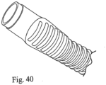
- a conduit for use in a respiratory apparatus for delivering breathable gas to a patient comprises a tube; a helical rib on an outer surface of the tube; and a plurality of wires supported by the helical rib in contact with the outer surface of the tube.
- the conduit may further comprise a connector block connected to an end of the conduit, wherein the connector block is configured to be connected to a flow generator or a patient interface of the respiratory apparatus.
- a method of delivering breathable gas to a patient comprises delivering a humidified flow of breathable gas to a patient interface via a conduit; heating the conduit by supplying a DC current at a predetermined duty cycle to a plurality of wires supported by the conduit; sensing a temperature in the conduit during an OFF cycle of the predetermined duty cycle; and controlling the DC current to maintain the temperature in the conduit at a selected temperature.
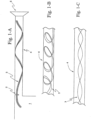
- Figs. 1-A to 1-C illustrate the use of a flexible tape heater 3 within the patient conduit 4 of a respiratory apparatus.
- the patient conduit 4 is located between the humidification chamber 1 and the patient interface, e.g. mask 5.
- the patient conduit 4 conveys the flow of gas from the humidification chamber 1 to the patient mask 5 in respiratory apparatus.
- the humidification chamber 1 in turn receives pressurized gas from a flow generator 20 ( Fig. 5 ) or blower.
- the flexible tape heater 3 in the patient conduit 4 is used to heat the flow of gas in the patient conduit 4. Heating of the gas enables the gas comfort features of temperature and humidity to be attained and maintained for the gas delivered by the respiratory apparatus.
- the flexible tape heater 3 is electrically coupled to a heater controller 21 ( Fig. 5 ) by a patient conduit connector end 2.
- the heater controller 21 may be incorporated in the humidifier or the flow generator 20 or the base unit 22, or be a separate unit 21, for example supplying a DC voltage of, for example, 0.1-24V.
- the patient conduit connector end 2 may connect to the heater controller 21 via another flexible tape heater (partially shown on the left side in Fig. 1 ) or to the conduit wall 25, of the patient conduit 4, via a connector 23, 24 shown in Figs. 6-A and 6-B .
- the connector may include a male connector element 23 and a female connector element 24 which may make an electrical, communications and/or mechanical connection between the flexible tape heater 3 and the conduit wall 25.
- the male connector element 23 and the female connector element 24 may be interchangeable in position.
- the connector 23, 24 locks the flexible tape heater 3 in position on the conduit wall 25, but may also be disengaged.
- the connector 23, 24 may be used at any location along or around the conduit wall 25.
- the patient conduit 4 may be insulated or a heated conduit as in the prior art in order to reduce heat loss and minimize consequent water condensation or "rain-out" within the patient conduit 4.
- the insulation could be an outer sleeve or wrapping about the patient conduit 4.
- the outer sleeve or wrapping could be foam, fabric or an air space in the case of a double walled conduit.
- the flexible tape heater 3 may be combined with the wall of the patient conduit 4 in order to provide heating to the wall to prevent condensation, while optionally an additional flexible tape heater 3 within the patient conduit 4 provides the heating to the gas flow.
- the patient conduit 4 is formed by making a helix of the flexible tape heater 3 and joining the edges the flexible tape heater 3 to form the patient conduit 4.
- the flexible tape heater 3 should be sufficiently flexible so that in use flexing of the patient conduit 4 is not restricted.
- the flexibility of the flexible tape heater 3 also should be sufficient to enable insertion and removal of the flexible tape heater 3 within the patient conduit 4, while being sufficiently stiff so that the flexible tape heater 3 can be inserted into the patient conduit 4 and will support itself in a desired position and not collapse against a wall or to one end of the patient conduit 4. Additionally the stiffness should be sufficient so that the flexible tape heater 3 will not flutter in the gas stream to produce an unwanted audible noise.
- the thin, flat and extended nature of the flexible tape heater 3 enhances heat transfer with the gas flow while also providing low impedance to the gas flow.
- the flexible tape heater 3 can be placed in the patient conduit 4 such that it has a helical configuration ( Fig. 1-B ) and/or the flexible tape heater 3 can be twisted or bent about one or more of the flexible tape heater 3 axes.
- the longitudinal axis twist configuration is illustrated in Fig 1-C .
- Alternative profiles or geometric structures for the flexible heating tape may include:
- the dimensions of the thickness and width may vary along the length of the flexible tape heater.
- a thicker section of the flexible tape heater 3 in the patient conduit 4 may be provided to give a venturi effect of increasing the gas flow rate so that flow detection may be possible by pressure sensors along the length of the flexible tape heater 3.
- the various configurations may also be used to provide zones of differing flow, acoustic, humidity or temperature properties along the patient conduit 4 or the apparatus as a whole, as show in Fig. 5 for example.
- the alteration of acoustic impedance properties using the flexible tape heater 3 may be achieved by the choice of the materials making up the flexible tape heater 3 and the configurations described above of the flexible tape heater 3 in the patient conduit 4, and additionally as shown in Figs. 1-A to 1-C .
- Fig. 2 illustrates one embodiment of the flexible tape heater 3, in which the heating is by a heating element 6.
- the heating element 6 is formed by printed circuit techniques applied to a surface of a flexible substrate such as KAPTON ® , silicone rubber, all-polyimide, PTFE. Included in the printed circuit techniques which may be used are etched foil, printing and vacuum deposition techniques.
- An alternative embodiment to produce a flexible tape heater 3 is to use a laminator, such as a twin silicon roller laminator, to encapsulate a heating element 6, that is in the form of wire or ribbon, within two tapes of polycarbonate film.
- the resulting tape may for example have dimensions ranging from 1 to 10 mm wide and 0.1 to 1 mm thick. Dimensions of from about 0.2 to 0.5 mm in thickness and about 5 mm wide are usable in the patient conduit 4.
- the heating element 6 wire or ribbon may have any suitable transverse cross-section, for example circular, elongate or rectangular.
- the heating element 6 may for example consist of a resistive conductor.
- the arrangement of the heating element 6 between the laminating films may be any ordered or disordered arrangement that increases the heat transfer of the flexible tape heater 3 to the surrounding media, be it gas or liquid.
- the heating element 6 may also have a positive thermal coefficient (PTC) for resistance such that heating decreases as the temperature increases towards a desired temperature.
- PTC positive thermal coefficient
- the heating element 6 may have a negative thermal coefficient (NTC) to allow sensing of the temperature of the heating element 6 or surrounding media.
- NTC negative thermal coefficient
- the multiple heating elements may be connected in series or parallel. The use of these multiple heating circuits within a flexible tape heater 3 enables additional heating to be applied as required in the operation of the respiratory apparatus.
- the laminating films may be polyester, polypropylene or any suitable and approved substance for respiratory medicine use.
- multiple laminating films may be used to create a composite strip having the desired properties while retaining the desired compatibility of the outer film for respiratory medicine use.
- Other conductors may also be present between each of these multiple layers, for example so as to form multiple heating circuits, such as to allow multiple heating zones along the length of the tape heater.
- a sensor 7 for air temperature such as a thermocouple, platinum resistance thermometer or thermistor with its attendant signal wires 9, may be included between the two sheets of polycarbonate film.
- the sensor tip may be flat with a thickness of less than about 2mm, and may be less than 1 mm.
- Other circuit components such as surface mount circuit components may be incorporated onto the substrate film for sensing and/or controlling and hence into the flexible tape.
- the heating element 6 and other circuit components can exist in multiple layers separated by substrate films as described above.
- the other circuit components all have the common physical feature that they are of a small enough dimension to enable them to be accommodated in the overall profile of the flexible tape heater 3 and collocated with the heating element 6.
- the flexible tape may not have a heater element 6, but instead incorporate one or more other circuit components for sensing and controlling.
- a respiratory apparatus may contain two or more flexible tapes, one or more undertaking a heating function and one or more undertaking a sensing and/or controlling function.
- thermocouple may be located on the flexible tape heater 3 at the end adjacent the patient mask 5 to enable closed loop temperature control based on gas temperature delivered to the patient mask 5.
- the temperature sensor may be located in or in the vicinity of the patient mask 5 but separated from the flexible tape heater 3. However the temperature sensor may communicate with the flexible tape heater 3 in the one of the manners described above to enable closed loop control of the temperature of the gas delivered to the patient.
- the flexible tape heater 3 may also comprise microtubes 26 ( Fig. 2 ) to allow remote sensing away from the flow generator and/or humidification chamber 1.
- the microtubes may, for example, provide pressure, noise/snore and/or cardiological signal sensing.
- the microtubes may be attached to the side of the flexible tape heater 3 and connected back to the flow generator 20 in one of the manners described above.
- the use of microtubes 26 provides the benefit of avoiding flow noise within the patient conduit 4 and other areas in the respiratory apparatus.
- the sensing and control methods described above allow closed loop control to be used for improving gas delivery to the patient mask 5 so that it is at the desired temperature and humidity.
- a simple open loop system may be used where driving voltages or currents for the heating element may be, for example, from 0.1 to 24 V direct current or the power equivalent for alternating current, that may for example be from 0.1 to 50 W.
- the sensing and control may also control the level of intentional gas leak from an active vent system, depending on the amount of pressure being supplied. For example, as the ventilator pressure increases the active vent system may be controlled to reduce the level of its intentional leak to an acceptable level.
- the sensors 7a can be used for compliance or statistical data gathering.
- the different components of the heater and/or sensing/control system described herein may be used as stand alone components in a respiratory apparatus not employing a humidifier, and such arrangements are within the scope of the invention.
- a flexible tape heater 3 as thus described would be easily removable from the patient conduit 4 to enable cleaning, maintenance or replacement.
- the flexible tape heater 3 also offers efficient heating with sensing and control components 7 being easily incorporated into the flexible tape heater 3.
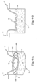
- a humidifier arrangement utilizing a floating heater 12 is illustrated.
- the floating heater 12 floats in the body of water 13 in the humidifier chamber tub 1 such that a substantial portion of the floating heater 12 is immersed but is still adjacent to the water surface 14 so as to heat that part of the water near the surface 14.
- the floating heater 12 may comprise a length of flexible tape heater of similar construction to that discussed above with reference to Figs 1-A to 1-C and 2 .
- the end of the heater located in the inlet conduit 10 leading from the flow generator 20 may be provided with a connector 11 which enables the floating heater 12 to connect with a flexible tape heater, where that flexible tape heater is connected to the base unit 22 ( Fig. 5 ) of the respiratory apparatus.
- the floating heater 12 receives its electrical supply via the upstream end connector 11. Any sensing or controlling signals to or from the floating heater 12 are also received via the upstream end connector 11.
- the downstream end 2 of the floating heater, located in the patient conduit 4 leading to the patient interface, may have a further connector for supplying power and any communication with a further portion of flexible tape heater located in the patient conduit 4 (see Figs. 1-A, 1-B, 1-C and 2 ).
- the heater 12 may be adapted to float either by the natural buoyancy of the heater itself, by surface tension effects, or may be supported in a manner which keeps the heater near the water surface regardless of changes in the water level.
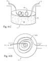
- Figs 4-A -E illustrate a number of embodiments that the floating heater 3, 12, 16, 17 may have within the humidification chamber 1.
- the floating heater 3, 12, 16, 17 in each embodiment is formed either from a flexible tape heater of the type previously described or a plate form of the flexible tape heater 3, the floating plate heater 16.
- a floating flexible tape heater 3 and the floating plate heater 16 is the same as described for the flexible tape heater 3 above, except that it is applied to water.
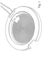
- Fig 4-A illustrates a circular floating plate heater 16 which is secured under a floating support grid or plate 15, for example of a buoyant plastics material.
- the support grid 15 provides a floating positioning mechanism for the floating plate heater 16 spacing the heater element just below the water surface 14 so that there is sufficient contact with the water to cause vaporization.
- the floating heater plate is located in a shallow bath that also floats at the water surface 14 of the body of water 13.
- the floating plate heater comprises at least one aperture to allow water to fill the bath to cover the heater plate 16. The small volume of water in the bath is rapidly heated to produce vapor.
- Fig. 4-B shows another embodiment where the plate form is rippled or dimpled in a regular or irregular fashion.
- the rippling and/or dimpling provides valleys which allow pockets of water to accumulate on the upper surface of the floating plate heater 16.
- the floating plate heater 16 is naturally buoyant, so it can float without the need for a support grid or other buoyancy device.
- Fig. 4-C illustrates a flexible tape heater 3 which has been wound into a helix.
- the floating, helical flexible tape heater 17 can intrinsically float such that a sufficient portion of the floating, helical flexible tape heater 17 is immersed in the body of water 13.
- the flexible tape heater 3 could be wound in a horizontal spiral, Fig. 4-D .
- a support grid 15 as used in Fig. 4-A may be used to position the flexible tape heaters 3, 12, 17.
- the preceding embodiments for the floating heater 3, 12, 16, 17 represent a number of defined configurations whereas in use the floating heater may assume a combination of the defined or undefined configurations. For example a long helix which continues as a spiral, combining Figs. 4-C and 4-D .
- the heater provides effective heat transfer to the water surrounding the heater.
- the water adjacent to the water surface is heated for vaporization rather than heating the whole body of water from the bottom up as in the case of a heater being located at the bottom of the body of water 13.
- the flexible tape heater formation may be spiraled or otherwise formed so as to be partly immersed in the body of water 13 so that it heats both the water near the air and the air near the water to produce a stratified zone of heat to improve water uptake for humidification.
- the floating heater 3, 12, 16, 17 may be more power efficient in generating water vapor, and more effective in quickly achieving the desired water surface temperature for humidification at start-up of the apparatus.
- Fig. 5 illustrates a respiratory apparatus which makes use of three heaters that are of the same general construction and use as described for the flexible tape heater 3 and the floating plate heater 12, 16, 17 described above.
- the heaters may comprise multiple heating circuits, so that each of the three heater zones may be operated independently.
- a flow generator 20 or blower supplies gas supplied from an ambient temperature supply which may be the air in the room or augmented or replaced by a specific gas supply such as oxygen.
- a pre-heater 18 is located in the blower coupling 10 leading to the humidifier 1.
- the blower coupling may be rigid, flexible or a conduit as required for the operation of the blower coupling 10 or the operation of the pre-heater 18 located within the blower coupling 10.
- the pre-heater 18 is connected to the controller/power supply 21, of the base unit 22, which supplies power and communication with any sensing or controlling components 7 of the pre-heater 18, as per the flexible tape heater 3 embodiment.
- the pre-heater 18 is connected to the floating heater 12, 16, 17 of the humidification chamber 1 at the blower conduit connector end 11.
- the floating heater 12, 16, 17 receives the controller/power supply 21 power supply and any communication, with the sensing or controlling components 7 of the floating heater 12, 16, 17, via the pre-heater 18.
- the floating heater 12, 16, 17 may also connect with the controller/power supply 21 via the wall of the blower coupling 10 in the manner described above in relation to Figs. 6-A and 6-B discussing the patient conduit 4.
- the post heater 19 is located in the patient conduit 4.
- the patient conduit connector end 2 provides the controller/power supply 21 power supply and communication for the sensing and controlling components 7 of the post heater 19.
- the patient conduit connector end 2 may connect to the controller/power supply 21 via floating heater 12, 16, 17 as shown in fig 5 or via the conduit wall 25, as shown in Figs. 6-A and 6-B , and then via the humidification chamber 1 to the controller/power supply 21 in the base unit 22.
- one or more of the heaters may not be of the type described above but another suitable heating element.
- the pre-heater 18 may be formed as a simple wire heater or other conventional heater type rather than as a flexible tape heater of the type described herein.
- the placement of the three heaters, and the timing and sequence of their use allows the gas comfort features of temperature and humidity to be managed by allowing the separate, staggered production of:
- Patient respiratory gas requires attention to the comfort features of temperature and humidity, in particular in winter and colder climates.
- the aim of the system from a cold start-up is to rapidly deliver warm gas initially and then increase humidity over time as the humidifier warms up. This approach allows the patient to receive comfortable warm air closely followed by an increasing relative humidity, before there is an onset of any adverse symptoms of low humidity respiratory assistance.
- the three heater system may thus operate in the following manner. Firstly, the cool ambient temperature gas from the flow generator 20 is warmed by using the pre-heater 18 in the blower coupling 10 with perhaps assistance from the post-heater 19 in the patient conduit 4. This initially provides warm, dry air to the patient.
- the post-heater 19 in the patient conduit 4 would begin or increase its heating in order to prevent "rain-out” condensation in the patient conduit 4.
- the initial warming of the air with the pre-heater 18 has the advantage of immediately commencing a degree of humidification, as a simple "pass-over” operation, while the floating heater 12, 16, 17 is still warming up the water. The heat for vaporization in the simple "pass-over” operation being provided by the heated air.
- the post-heater 19 in the patient conduit 4 would adjust its heating to maintain the absolute humidity by preventing condensation in the patient conduit 4.
- the post-heater 19 may also serve to maintain the desired gas temperature in the patient conduit 4.
- the pre-heater 18 may have a heating profile based on the level of heating of the body of water 13 in the humidification chamber 1, the heating profile being the rate of heating of the gas flow in a period of time that can be provided by changing the power to the pre-heater 18 or the structural configuration of the pre-heater 18. It is believed that there may be more effective and control of the humidity by controlling the air temperature as opposed to heating the water.
- An additional advantage of this sample embodiment is that it allows reduced power consumption at humidification start up so that the respiratory apparatus may be able to be operated by direct current power supply or a portable power supply. Also, satisfactory operation can still be obtained when two or more heaters are multiplexed, one heater is operated at a time but there is cycling in operation between two or more heaters.
- the power supply/controller 21 may be connected to the inlet conduit/blower coupling 10 by a connector 52.
- the connector 52 has a first connector 52a connected to the power supply/controller 21 and a second connector end 52b connected to the inlet conduit 10.
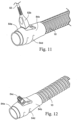
- the inlet conduit 10 has a flow generator cuff or connector 54.
- the flow generator cuff 54 has an end 54a which is configured for connection with the flow generator 20.
- the flow generator cuff 54 also has an overmolded grip or cuff 54b which defines a terminal clip 54c.
- the inlet conduit 10 is connected to the flow generator 20 by the flow generator cuff 54.
- the connector 52 is connected to the flow generator cuff 54 at the terminal clip 54c.
- the first end 52a of the connector 52 is connected to the power supply/controller 21.
- the power supply/controller 21 provides electrical current and signals to the flow generator cuff 54 through the connector 52.
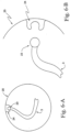
- the patient conduit/air delivery hose 4 is connected to the patient interface 5 by a mask connector or cuff 56, as shown in Fig. 10 .
- the patient conduit 4 includes a tube 4a, for example of thermoplastic elastomer, and a helical rib 4b of very low density polyethylene. Wires 4c, 4d, 4e are supported in the helical rib 4b so as to be in contact with the outer surface of the tube 4a. The wires 4c, 4d, 4e may be used to heat the tube 4a and to carry signals to and from the power supply/controller 21.
- the inlet conduit 10 may have a construction similar to the patient conduit 4, including a tube 10a, a helical rib 10b, and wires 10c-10e supported by the helical rib on the tube.
- the flow generator cuff 54 includes a connector block 54a.
- a grip or cuff 54b is overmolded on the connector block 54a to connect the connector block 54a to the inlet conduit 10.
- the overmolded grip or cuff 54b includes grip features 54d, such as recesses for a user's fingers, in the outer surface of the overmolded grip or cuff 54b to provide a better grip on the connector cuff 54.
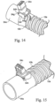
- the flow generator cuff 54 includes a terminal clip 54c that receives the second connector end 52b of the connector 52.
- the terminal clip 54c includes a rib 54n that is received in a lead-in 52e of the connector 52. The rib 54n engages the lead-in 52e to secure the connector 52 to the terminal clip 54c.
- the terminal clip 54c also includes a tooth 54e that locates the wires 10c, 10d, 10e of the inlet conduit 10.
- the wires 10c, 10d, 10e are placed on the outer surface of the thermoplastic elastomer tube 10a and held in place on the outer surface by the helical rib 10b.
- a channel 54j is provided in the connector block 54a to allow the overmolded material 54b to flow and bond to the inside of the tube 10a to establish the connection between the connector block 54a and the inlet conduit 10.
- the connector block 54, the tube 10a and the overmolded material 54b may be formed of materials that will chemically bond.
- the terminal clip 54c includes terminal clip pins 54h that are received in hinged slots 54g of a terminal clip hinge 54f.
- the terminal clip hinge 54f is provided on the connector block 54a.
- the terminal clip 54c is snap-fit into the terminal clip hinge 54f to ensure connection of the tooth 54e with the wires 10c, 10d, 10e of the inlet conduit 10.
- the terminal clip 54c may be attached to the connector block 54a prior to attachment of the inlet conduit 10 to the connector block 54a.
- the terminal clip pins 54h are attached in the hinge slots 54g and the terminal clip 54c is tilted or rotated forward.
- the inlet conduit 10 is then attached to the connector block 54a and the terminal clip 54c is then rotated or pivoted back so that the tooth 54e contacts the wires 10c, 10d, lOe of the inlet conduit 10.
- the connector block 54a includes a guide away 54p for the helical rib 10b of the inlet conduit 10 to position the wires 10c, 10d and 10e for contacting by the tooth 54e.
- the terminal clip 54c includes an arched portion 54k that defines a channel with the guide way 54p ( Fig. 16 ) when the terminal clip 54c is inserted into the terminal clip hinge 54f.
- a groove 54i ( Fig. 18 ) is provided in the connector block 54a to receive the helical rib 10b and the wires 10c, 10d, 10e of the inlet conduit 10.
- the groove 54i has a smooth surface and wide contact area to prevent or minimize damage to the wires 10c, 10d, 10e.
- a void 54m is provided adjacent to the channel 54j to allow for the passage of any air during the overmolding of the grip or cuff 54b to the connector block 54a.
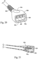
- the second connector end 52b has a grip feature 52c to permit easier gripping of the second connector end 52b.
- Strain relief features 52d are also formed in the second connector end 52b to increase flexibility. The grip and strain relief features may also be provided to the first connector end 52a of the connector 52.
- Contacts 52f, 52g, 52h are provided for sending and receiving signals from the wires 10c, 10d, 10e of the inlet conduit 10.
- the inlet conduit 10 is shown as including three wires and a terminal clip 54c is shown as having three terminals for receipt of the three contacts of the second connector end 52a, it should be appreciated that any number of wires, terminals and contacts may be used for the delivery and receipt of signals from the power supply/controller 21 to the inlet conduit 10.
- a mask connector or cuff 56 is provided for the connection of the patient conduit/air delivery hose 4 to the patient interface 5.
- the mask connector or cuff 56 includes a connector block 56a that is connected to the patient conduit 4 by an overmolded grip or cuff 56b.
- the connector block 56a, the tube 4a and the overmolded cuff 56b may be formed of materials that will chemically bond.
- the connector block 56a is connected to an inlet 5a of the patient interface 5.
- the inlet 5a may be, for example, the swivel elbow of a mask.
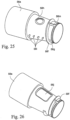
- a printed circuit board (PCB) 56c is provided around the outer surface of the connector block 56a.
- the wires 4c, 4d, 4e of the patient conduit 4 are attached to the PCB 56c.
- the connector block 56a includes snaps or pins 56i that engage holes or apertures 56u in the PCB 56c.
- the PCB 56c is thus wrapped around an outer surface of the connector block 56a and held in place.
- a thermal fuse 56d and a temperature sensor 56e for example a thermistor, are provided on the PCB 56c.
- one or more windows 56j are provided in the outer surface of the connector block 56a where the thermal fuse 56d and the temperature sensor 56e are provided.
- the windows 56j are covered by the PCB 56c, as shown in Fig. 24 .
- the PCB 56c includes a heater track that is cooled by exposure of the PCB 56c to the airflow along the window 56j.
- a helical rib 56f is provided on the outer surface of the connector block 56a to locate the patient conduit 4, as shown in Figs. 22-26 .
- the outer surface of the connector block 56a includes a stepped recess 56h to allow the overmold material to flow and bond to the underside of the flexible PCB 56c.
- the connector block 56a also includes a channel 56t to allow the overmold material to bond with the inside of the tube 4a of the patient conduit 4.
- a void 56g is provided adjacent the channel 56t to allow for the escape of air during overmolding.
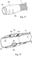
- the end of the connector block 56a includes a profile 56n that minimizes the capacity for debris to collect and to be cleaned if debris does collect. The end of profile 56n also minimizes flow impedance of the overmolded material.
- an access channel 56m is provided between the helical rib 56f and the end channel 56t to allow the overmold material to bond the tube 4a to the connector block 56a.
- the tube 4a is twisted on to the connector block 56a and the wires 4c, 4d, 4e of the patient conduit 4 are soldered to the flexible PCB 56c as shown at 56p.
- the overmolded grip or cuff 56b may include a molded grip feature 56q, such as recesses to accommodate a user's fingers, to improve the gripping ability of the mask cuff or connector 56.
- the connector block 56a may be formed of a rigid polymer and the overmolded grip or cuff 56 may be formed of a thermoplastic elastomer.
- the connector block 56a may have a standard 22 mm ISO taper for connection to the patient interface.
- the overmolded material may be blanked off at 56s in the region of the thermal fuse 56d.
- the circuit on the flexible PCB 56c includes the thermal fuse or switch 56d and the thermal sensor 56e.
- One of the wires, e.g. 4c may be used as a temperature sensing wire for sending a temperature signal to the power supply/controller 21.
- the other wires, e.g. 4d, 4e may be used as heater wires to heat the tube 4a of the patient conduit 4. If the temperature exceeds a certain value, the thermal fuse 56d is configured to cut off current to the heater wires 4d, 4e.
- the flexible PCB 56c and temperature sensor 56e and thermal fuse 56d should be provided on the connector block 56a as close to the inlet 5a of the patient interface 5 and the air path through the patient conduit 4 as possible.
- the mask connector or cuff 56 should also be formed as small as possible to permit its use with existing breathing apparatus.
- the use of the overmolded grip or cuff 56b is also useful for securing the patient conduit 4 to the connector block 56a and to secure the flexible PCB 56c, including the temperature sensor 56e and the thermal fuse 56d in place.
- the use of the overmolded material also helps to reduce or eliminate any locations where bacteria could grow.
- the mask connector or cuff 56 as described herein is formed of biocompatible materials.
- the connector block 56a also includes an end 56r ( Fig. 32 ) that includes a standard 22 mm female ISO taper for use with existing patient interfaces.
- the use of the overmolded material also eases manufacture and improves reliability of the mask connector or cuff.
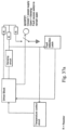
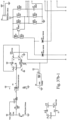
- the power supply/controller 21 comprises a switch mode power supply 21a, a switch 21b, a control unit 21c, and a plurality of LED's 21d.
- the power supply/controller 21 has an AC power input 21e, a DC power output 21f, and a bypass AC power lead 21g to the flow generator 20.
- the AC power input 21e may be, for example, 110-240V AC universal inputs.
- the switch 21b may be a MOSFET switch in series with the heater element controlled by the control unit 21c.
- the DC power output 21f may be, for example, a 500mA regulated 5V DC, or a 1.3A, 24V DC output. At 24V the power output is 30W.
- the power input 21e is connected to the switch mode power supply 21a and the bypass 21g is connected to an AC power socket of the flow generator 20.
- the power supply/controller 21 is configured to provide power to the inlet conduit 10, regulate preset temperature levels at the patient interface 5, and act as an ON/OFF control.
- the control unit 21c is a closed loop temperature control system.
- the temperature sensor 56e located in the mask cuff 56 provides the feedback signal through the wire 4c of the patient conduit 4 back to the control unit 21c. It should be appreciated, however, that the control may not rely on a feedback of a temperature signal.
- the control unit 21c may instead be configured to provide a predetermined amount of power to the output 21f without reliance, or dependence, on a temperature sensor signal.
- the DC power output 21f supplies power to the inlet conduit 10 and the switch 21b is provided in series with the power output 21f and is controlled by the control unit 21c.
- the power regulation is based on an ON/OFF control technique.
- the power regulation has fixed duty cycles at a rate of about 95 - 99%.
- the OFF cycle, at a rate of about, for example 1 - 5%, is used for temperature sensing.
- the LEDs 21d may include a green LED to indicate that power is on and being supplied to the inlet conduit 10.
- An amber LED may be provided to indicate that the power output 21f is ON, but not provided to the inlet conduit 10.
- a red LED may be provided to indicate a fault.
- Further LEDs may also be provided for indicating and/or controlling the temperature. Manually operable buttons (not shown) may be provided to the power supply/controller to allow control of the temperature by a patient or clinician in response to an indication of temperature by the LED's.
- the control unit 21c is configured to produce a fixed power switching frequency and duty cycles for the power output 21f to heat the inlet conduit 10.
- the control unit 21c is also configured to sense the temperature via the signal sent by the temperature sensor 56e through wire 4c. Based on the sensed temperature, the control unit 21c is configured to regulate the temperature to a preset temperature when ambient temperature changes.
- the control unit 21c is further configured to record the preset temperature when the power control/supply 21 is turned off.
- the control unit 21c may also latch a fault state when a fault is detected, and clear the fault by recycling power. If a fault occurs a fault detection circuit locks into a fault condition to send a fault signal to a driver block ( Fig. 37a ) the fault will continue until the power is turned OFF and ON again.
- the control unit 21c may be configured to detect faults, including any discontinuities in the wires 4c-4e and 10c-10e, any arcing and/or bad connections in the flow generator cuff 54 and/or the mask cuff 56. The control unit 21c may also detect low voltage.
- the power output 21f is maintained in the OFF state by the control unit 21c when a fault is detected and is maintained in the OFF state until the power is recycled and the fault state is cleared.
- the status of the power supply/controller 21 may be indicated through the LEDs 21d. -
- the power supply/controller 21 may be separate from the flow generator 20 and the humidifier. There is no information exchange between the flow generator 20 and the humidifier and the closed loop control does not include control based on airflow rate, humidity level, and humidifier outlet temperature, for example. It should be appreciated, however, that information may be exchanged, for example through the sensing wire 4c.
- the control described above prevents "rain out” in the patient conduit 4 and delivers the humidified air to the patient interface 5.
- the power supply/controller 21 may be integrated with the flow generator 20 or the humidifier control system. Information may be provided to the integrated power supply/controller regarding the operation of the flow generator, the humidifier, and ambient air. By integrating the power supply/controller with the flow generator 20 or the humidifier, the system will be more able to control the temperature at the patient interface 5, the humidity levels and "rain out” at a wider range of ambient temperature and humidities.
- the wires 4d, 4e may be formed, for example, from a 25m long wire having a diameter of 0.23mm, and be formed, for example, of copper.
- the sensing wire 4c may be connected to the heating wires 4d, 4e at a connection point 4f that is approximately the middle of the wire forming the wires 4d, 4e and divides the wire into two resistances Ra, Rb.
- the total resistance Ra + Rb may be equal to about 15 - 21 ⁇ , for example about 18 ⁇ , at 20° - 26°C, for example about 23°C.
- the total resistance Ra + Rb is about 18 ⁇ , , and about 21 ⁇ ,w hen the wire resistors are heated up to about 33°C using a 24V DC supply at a power of about 30W.
- the DC voltage V+ may be supplied across J1 and J3 at a duty cycle of, for example, about 95 - 99%.
- the resistances Ra, Rb generate heat during the flow of current through the wires 4d, 4e to heat the conduit 4.
- the sensing voltage Vsen may be determined during the 1 - 5% OFF cycle.
- the switch 21b is activated by the control unit 21c to switch the system into a sensing state and sensing current from J1 passes resistance Ra and resistance RT1 of the temperatures sensor 56e back to J2.
- the resistance RT1 of temperature sensor 56e may be about 1-50 k ⁇ and resistance Rb may be about half of Ra + Rb, or about 5 - 15 ⁇ , for example about 10 ⁇ , so Rb is omitted.
- sensing wire 4c is disclosed as being connected to the temperature sensor 56e, it should be appreciated that the sensing wire may be connected to a different sensor, such as a pressure sensor, for example in the event that the control is not a feedback control based on the detected temperature.
- the fuse F2 of the thermal circuit 56d is thermally coupled to the heater track of the PCB 56c.
- the PCB 56c may be, for example, about 0.05 - .15 mm thick, for example about 0.1 mm thick, have a resistance of about 0.05 - .15 ⁇ , for example about 0.1 ⁇ , and a power output of about 0.12 - 0.24 W, for example about 0.18W.
- one side of the PCB 56c faces the open window 56j so the PCB 56c contacts the air in the patient conduit 4. The air flowing in the conduit therefore cools the PCB 56c to just above the temperature of the air in the conduit.
- the thermal circuit 56d may include a thermostat, for example a bi-metal strip, instead of the fuse, and an increase in impedance of the thermostat would act to suppress, or stop, an increase in the current.
- the power supply/controller 21, the mask cuff 56 and its components, and the patient conduit 4 should comply with safety standards for temperature regulation, for example, ISO 8185.
- the patient or clinician should be able to set the temperature of the air delivered to the patient interface 5 from ambient to about 30°C. If no alarm system or indicator is provided to the system, in accordance with ISO 8185, sections 51.61-51.8, under normal and single fault conditions, the temperature of the air delivered to the patient interface 5 should not exceed about 40°- 42°C, for example about 41°C. This maximum temperature (e.g. 41°C) is under the maximum energy level of 43°C at 100% RH.
- the fuse F2 of the thermal circuit 56d may be chosen to trip off at the maximum temperature.
- the three wire (4c-4e) electrical circuit of the patient conduit 4 includes the heating elements Ra, Rb in series with the heater track and fuse F2 of the PCB 56c, the wire 4c for supplying the sensing voltage Vsen, and the thermal sensor 56e including the thermal resistor TR1 attached to the middle 4f of the of the heater wires 4d, 4e.
- the electrical circuit has two states: ON and OFF. In the ON state, also referred to as the heating state, the wire 4d is connected at J1 to the voltage V+, for example the 24V DC from the power output 21f. The heating current flows through J3, wires 4d, 4e, J4 and the switch 21b and into ground GND. In the ON state, the sensing voltage Vsen at J2 will not sense the air temperature, but will sense about half of voltage V+, e.g. about 12V.
- the switch 21b In the OFF state, the switch 21b is switched off and the heater wires 4d, 4e will be pulled up by V+, e.g. about 24V, and the sensing current passes through J1, Ra, RT1 and back to J2.
- V+ e.g. about 24V
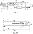
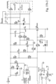
- the power supply/controller 21 may include circuits for performing numerous functions. These circuits may include: 1) a power switching control circuit; 2) a tube interface and gate drive circuit (driver block); 3) a fault detection and latching circuit (fault detection latch); 4) a temperature preset/control circuit; and 5) a start up and indication circuit.
- the circuit includes a temperature control circuit configured to control the temperature of the heated conduit(s), a fault detection latch, a sensing circuit and a driver block.
- the driver block is connected to the switch 21b, which may be a MOSFET.
- a sample embodiment of the circuit of Fig. 37a may be based on, for example, an UC2843 control IC, available from Texas Instruments. It should be appreciated that other control circuits may be used.
- the power switching control circuit has chip over-current and over-voltage protections which can be used for error handling.
- the power switching control circuit of Figs. 37b-1 - 37b-4 drives the transistor gate of the switch 21b at about 98.62% duty cycles.
- the ON state of the circuit cannot be interrupted by Vfb signals.
- the gate signal can be shown as 50% 69 Hz outputs.
- the power switching control circuit has enable input through the Vfb pin. When any of the signals through D3 and D4 to low, it will disable the output of the switch 21c.
- the sensing current Isen is not used for this application as R10 and R20 set the sensing voltage Vsen below 1V.
- the sensing voltage Vsen has two functions: 1) when the heater power is ON, the sensing voltage Vsen detects the heater wires continuity, or any arcing or bad connections by sensing middle voltage V+; and 2) when the heater power is OFF, the sensing voltage Vsen senses the air temperature via the RT1 and R13 divider voltages.
- the Q2, Q3 network provides right logic for sensing operations and MOSFET Q3 provides low impedance (Rdson) for temperature sensing.
- Q4 MOSFET gate drives network R23, R25 limiting the maximum gate voltage; R24 and D5 together with R23 control the Q4 switch off speed.
- the fault detection circuit operates when heater power is ON.
- the Vsen signal is fed into a window comparator, for example an ultra-power quad comparator, such as the LP339AM, available from National Semiconductor.
- U6B, U6D; R31, R36 and R43 divider provide a +/- 2V window voltage at 12 Volt; the output of window comparator signals will feed into second stage of the comparator U6C.
- the second stage of comparator samples the Q4 gate signal as a base line and detecting the error signal from window comparator output.
- window comparator outputs as high impedance, R34 and R40 divider has higher voltage out then inverting comparator input R33 and R42 divider network, U6C will output high.
- window comparator When the system has a fault detected, window comparator outputs low, R34 and R40//R35 divider has lower voltage then inverting comparator input R33 and R42 divider network, U6C will output low to U2A latch CLR pin.
- latch CLR pin 1 When latch CLR pin 1 receives a low signal the Q pin 5 will output a latched fault signal, it will kill the U3 output switching signals.
- the latch may be, for example, a 74HCT74D U2A from Fairchild Semiconductor.
- the temperature sensing operation is only performed during the power OFF period.
- the air temperature sensor RT1 and divider base resistor R13 provides the temperature information Vsen, it directly feed into the comparator U6A inverting input, a potentiometer and it's network does the temperature preset function.
- the output of this comparator drives D4 and controls the U3 switch output.
- the start up circuit provides a 140mS delay when system start up and it will reset the latch. After reset, the system will at ON state.
- the start up circuit may be, for example, an IC U4 TCM809, available from TelCom Semiconductor, Inc.
- the accuracy of temperature measurement is based on two parts: 1) sensing accuracy; and 2) accuracy of reference. Sensing accuracy depends on NTC thermistor RT1 and series resistor R13. For example, a good NTC sensor RT1 may have up to a 1 - 5%, for example about 3%, accuracy tolerance; the series resistor R13 may have up to a 0.5 - 1.5% tolerance, for example about a 1% tolerance.
- the accuracy of the temperature preset circuit is determined when the port is at highest setting (30°C). The port resistor is 0 ⁇ and the accuracy is dependent on the 1% resistor network. However, when the port is set to the lowest setting, 20% of the port resistor tolerance will be added in.
- the conduits 4 and 10 will overheat when there is no gas flow in the tubes.
- the heat can be accumulated in the tube, if the tube is covered, for example under a quilt, and the heater element temperature can rise to 120-150°C.
- the heat can accrue when the thermal switch is exposed in cold air, but part of the tube was covered, for example under the quilt. For this reason, a no flow or low flow signal from the flow generator should able to trip off the heated tube power supply.
- a three way connector is provided between thermistor sensor RT1 and the control unit 21c. Any bad connection on the contactor will cause increasing impedance on the sensing circuit; for NTC thermistor RT1 it will lower the temperature readings, and it can cause air temperature rise and may trip the thermal switch 21b at the tube.
- a first way is to change the voltage divider logics, as contact resistance is high the air temperature goes low.
- the other way to protect the sensing contactor is to off-set the sensing wire by changing R6 and R31 to 8.2 k ⁇ This offset refrence voltage can detect the high impedance connectors.
- the configuration of the inlet conduit connector cuff and/or the patient conduit and mask connector cuff may take various forms.
- Each of the mask connector or cuff configurations shown and described herein may include grip features, and sufficient strain relief features to improve the flexibility of the connector or cuff.
- the inlet conduit 10 and/or the patient conduit 4 may include an inner tube 4a, 10a, a helical rib 4b, 10b, and an outer tube 4f, 10f.
- the outer tube 4f, 10f may be formed of the same material as the inner tube 4a, 10a.
- the outer tube 4f, 1 0f may also be provided with a fleece or flocked material to improve the feel and/or grip of the conduit, and/or to improve the thermal insulation properties of the tube and/or the visual appeal. If the outer tube 4f, 10f is not provided, the outer surfaces of the inner tube 4a, 10a and the helical rib 4b, 10b may be provided with a fleece or flocked material for similar reasons.
- the inlet conduit 10 and/or the patient conduit 4 may include an inner tube 4a, 10a and an outer tube 4f, 10f spaced by corrugations 4g, 10g.
- the corrugations 4g, 10g may extend axially along the conduit 4, 10, or may extend helically along the conduit 4, 10. Wires may be provided within the corrugations 4g, 10g, between the inner tube 4a, 10a and the outer tube 4f, 10f.
- the corrugations may also be used to provide a supplemental gas flow along the conduit 4, 10, or to provide a flow of liquid, for example water, to regulate the temperature of the gas flow in the conduit 4, 10.
- the corrugations may also be used to exhaust gas, for example from the patient's exhalation, from the patient interface.
- the outer tube 4f, 10f may also be covered in fleece or flocked material.
- a patient conduit 400, mask connector cuff 560 and flexible circuit 570 according to another sample embodiment are illustrated.
- the patient conduit 400 is connected to the mask cuff 560 by an overmold material 580 that encompasses the flexible circuit 570.
- the overmold material 580 is overmolded onto the patient conduit 400 and the mask cuff 560.
- the flexible circuit 570 may include the tube wires, sensors, fuses and other components described above in relation to the other sample embodiments.
- the mask cuff 560 may be formed as a separate part that is connected to the patient conduit 400 through the overmold material 580. Alternatively, the mask cuff 560 may be formed as a single piece with the overmold material. 580.
- the heating wires may be PTC elements with a voltage regulation to limit the temperature of the wires ad/or the air in the conduit(s).
- one or more PTC or NTC wires may be used in conjuction with a resistor to limit the temperature of the wires and the air.
- NTC wires may be used with a current regulator, or a measure resistance, to limit the temperature of the heating wires. The temperature sensing and heating may also be performed using only two wires.
Abstract
Description
- This application claims priority to
U.S. Application 60/955,222, filed August 10, 2007 Australian Provisional Application 2006906224, filed November 8, 2006 - The present invention relates to humidification and heater arrangements used to control the humidity of breathable gases used in all forms of respiratory apparatus ventilation systems including invasive and non-invasive ventilation, Continuous Positive Airway Pressure (CPAP), Bi-Level therapy and treatment for sleep disordered breathing (SDB) conditions such as Obstructive Sleep Apnea (OSA), and for various other respiratory disorders and diseases.
- Respiratory apparatus commonly have the ability to alter the humidity of the breathable gas in order to reduce drying of the patient's airway and consequent patient discomfort and associated complications. The use of a humidifier placed between the flow generator and the patient mask, produces humidified gas that minimizes drying of the nasal mucosa and increases patient airway comfort. In addition in cooler climates, warm air applied generally to the face area in and about the mask, as may occur inadvertently by a leak, is more comfortable than cold air.
- Many humidifier types are available, although the most convenient form is one that is either integrated with or configured to be coupled to the relevant respiratory apparatus. While passive humidifiers can provide some relief, generally a heated humidifier is required to provide sufficient humidity and temperature to the air so that patient will be comfortable. Humidifiers typically comprise a water tub having a capacity of several hundred milliliters, a heating element for heating the water in the tub, a control to enable the level of humidification to be varied, a gas inlet to receive gas from the flow generator, and a gas outlet adapted to be connected to a patient conduit that delivers the humidified pressurized gas to the patient's mask.
- Typically, the heating element is incorporated in a heater plate which sits under, and is in thermal contact with, the water tub.
- The humidified air may cool on its path along the conduit from the humidifier to the patient, leading to the phenomenon of "rain-out", or condensation, forming on the inside of the conduit. To counter this, it is known to additionally heat the gas being supplied to the patient by means of a heated wire circuit inserted into the patient conduit which supplies the humidified gas from the humidifier to the patient's mask. Such a system is illustrated in Mosby's Respiratory Care Equipment (7th edition) at page 97.
- Such a heating method for the patient conduit may only provide poor heat transfer due to the wire locating itself along the conduit wall rather than in the main gas stream. A wire will also only give poor turbulent mixing due to its low profile. As a result heat transfer may be poor and the mixing of water vapor and gas may also be poor.
- Alternatively the heating wire circuit may be located in the wall of the patient conduit. Such a system is described in
U.S. Patent 6,918,389 . -
U.S. Patent 6,918,389 describes a number of humidifier arrangements for supplying low relative humidity, high temperature humidified gas to the patient. Some of these arrangements include pre- or post-heating of the gas to reduce the relative humidity. - None of these prior art devices provides an entirely satisfactory solution to the provision of comfortable humidified breathable gas to the patient, nor to ease of construction and hygiene requirements and to energy and patient comfort requirements at startup.
- Examples of the present invention aim to provide an alternative humidifier arrangement which overcomes or ameliorates the disadvantages of the prior art, or at least provides a useful choice.
- In one sample embodiment of the invention, a humidifier and/or temperature or other sensing or control apparatus for use with respiratory apparatus comprises a heating filament in thermal contact with the gas and/or water, wherein the filament is in the form of an elongate tape. The tape may be flexible, and may, in a sample embodiment, be passed along the bore of the patient gas conduit, or incorporated into the conduit wall.
- In another sample embodiment, a humidifier for use with respiratory apparatus comprises a heater in contact with water in the humidifier tub, and which floats or otherwise rises and falls with changes in the water level in the humidifier tub.
- In a further form, the invention provides a humidifier arrangement for respiratory apparatus, including an elongate filament heater in contact with the air path in the regions before and after the humidification chamber. The filament heater may be further in contact with a body of water in the humidification chamber.
- Heating of the filament may be divided into two or more separately controllable zones.
- A further sample embodiment of the invention provides a method of increasing patient comfort during start-up of humidification, the method comprising providing a heating element to thermally contact breathable gas being provided to the patient along a gas flow path and to thermally contact water in a humidifier apparatus; and configuring the heating element to heat the gas in the gas flow path and to heat the water in the humidifier apparatus, such the patient is initially provided with heated gas while the temperature of the water in the humidifier apparatus is being increased to its operating temperature.
- The heating of the gas in the gas flow path may include heating of a part of the gas flow path upstream of a humidification chamber such that passage of the heated gas through the humidifier apparatus provides an initial degree of humidification.
- According to a sample embodiment of the invention, a conduit for use in a respiratory apparatus for delivering breathable gas to a patient comprises a tube; a helical rib on an outer surface of the tube; and a plurality of wires supported by the helical rib in contact with the outer surface of the tube.
- According to another sample embodiment of the invention, the conduit may further comprise a connector block connected to an end of the conduit, wherein the connector block is configured to be connected to a flow generator or a patient interface of the respiratory apparatus.
- According to a further sample embodiment of the invention, a respiratory apparatus for delivering breathable gas to a patient, comprises a flow generator to generate a supply of pressurised gas to be delivered to the patient; a humidifier to vaporize water and to deliver water vapor to humidify the gas; a first gas flow path leading from the flow generator to the humidifier; and a second gas flow path leading from the humidifier to a patient interface, wherein the first gas flow path comprises a first conduit having a first connector block configured to be connected to the flow generator and the second gas flow path comprises a second conduit having a second connector block configured to be connected to the patient interface.
- According to still another sample embodiment of the invention, a method of delivering breathable gas to a patient comprises delivering a humidified flow of breathable gas to a patient interface via a conduit; heating the conduit by supplying a DC current at a predetermined duty cycle to a plurality of wires supported by the conduit; sensing a temperature in the conduit during an OFF cycle of the predetermined duty cycle; and controlling the DC current to maintain the temperature in the conduit at a selected temperature.
- Embodiments of the invention will now be described with reference to the accompanying drawings, in which:
-
Fig. 1-A is a schematic side sectional view of the patient conduit with a flexible tape heater in an embodiment of the present invention; -
Fig. 1-B is an alternative embodiment ofFig. 1-A where the flexible tape heater is in a helical configuration; -
Fig. 1-C : is an alternative embodiment ofFig. 1-A where the flexible tape heater is twisted about its longitudinal axis; -
Fig. 2 is a schematic perspective view of another embodiment of the flexible tape heater; -
Fig. 3 is a schematic side sectional view of the humidification chamber with an embodiment of the floating heater; -
Figs. 4-A-D schematically illustrate a number of embodiments that the floating heater may have within the humidification chamber; -
Fig. 4-A is a side perspective view of an embodiment of the floating heater, a circular floating plate heater which is secured under a floating plastic support grid; -
Fig. 4-B is a side perspective view of another embodiment of a floating heater; -
Fig. 4-C is a perspective side view of another embodiment of a floating, helical flexible tape heater; -
Fig. 4-D is a plan view of another embodiment of a flexible tape heater wound in a horizontal spiral; -
Fig. 5 schematically illustrates a humidification heater arrangement comprising multiple zones; -
Fig. 6-A is a transverse cross-sectional view of the patient conduit showing the flexible tape heater connected to the conduit wall; -
Fig. 6-B is another view of the connector embodiment ofFig. 6-A where the connector is disengaged; -
Fig. 7 illustrates the floating heater plate located in a shallow bath that also floats at the water surface of the body of water; -
Fig. 8 illustrates a power supply/controller connected to an inlet conduit by a connector according to a sample embodiment of the invention; -
Fig. 9 illustrates the inlet conduit ofFig. 8 connected to a flow generator; -
Fig. 10 illustrates a patient conduit or hose according to a sample embodiment of the invention connected to a patient interface; -
Fig. 11 illustrates an inlet conduit, including a flow generator connector cuff, connected to a connector according to a sample embodiment of the invention; -
Fig. 12 illustrates the inlet conduit ofFig. 11 disconnected from the connector; -
Fig. 13 illustrates a cross section of the inlet conduit and connector ofFig. 11 ; -
Fig. 14 is a rear perspective view of the inlet conduit and portions of the flow generator connector cuff with the terminal clip connected thereto; -
Fig. 15 is a front perspective view of the inlet conduit, flow generator connector cuff portions, and terminal clip ofFig. 14 ; -
Fig. 16 is a top perspective view of the inlet conduit and flow generator connector cuff portions without the terminal clip; -
Fig. 17 is a perspective view of the terminal clip according to a sample embodiment of the present invention; -
Fig. 18 is a perspective view of the connector block of the flow generator connector cuff according to a sample embodiment of the invention; -
Fig. 19 is a perspective view of the connector according to a sample of the invention; -
Fig. 20 is a perspective view of the contacts of the connector ofFig. 19 ; -
Fig. 21 is a cross section of the contacts and the connector ofFig. 20 ; -
Fig. 22 is a perspective view of the patient conduit or hose and portions of the mask cuff or connector according to a sample embodiment of the invention; -
Fig. 23 is a cross section of the patient conduit and mask cuff ofFig. 22 with portions of the cuff removed; -
Fig. 24 is a cross section of the patient conduit and mask cuff ofFig. 10 ; -
Fig. 25 is a top perspective view of the connector block of the mask cuff according to a sample embodiment of the invention; -
Fig. 26 is a bottom perspective view of the connector block ofFig. 25 ; -
Fig. 27 is a top perspective view of the connector block of the mask cuff in connection with the patient conduit and including a printed circuit board of the mask cuff according to a sample embodiment of the invention; -
Fig. 28 is a side perspective view of the connector block ofFig. 27 disconnected from the patient conduit; -
Fig. 29 is a cross section of the patient conduit and connector block ofFig. 27 ; -
Fig. 30 is a perspective view of the patient conduit and the connector block of the mask cuff according to a sample embodiment of the invention; -
Fig. 31 is a perspective view of the patient conduit and mask cuff according to a sample embodiment of the invention; -
Fig. 32 is a cross section of the patient conduit and mask cuff ofFig. 31 ; -
Fig. 33 is a schematic illustration of the temperature sensor and thermal fuse of the circuit of the mask cuff according to a sample embodiment of the invention; -
Fig. 34 schematically illustrates the circuit of the mask cuff provided on the connector block of the mask cuff; -
Fig. 35 schematically illustrates power supply/controller according to a sample embodiment of the present invention; -
Fig. 36 schematically illustrates a three wire heated tube according to a sample embodiment of the invention; -
Fig. 37a schematically illustrates a sample embodiment of the circuits of the power supply/controller; -
Figs. 37b-1 - 37B-4 schematically illustrate a sample embodiment of the circuit ofFig. 37a ; -
Figs. 38-40 are perspective views of overmolded grip portions for the flow generator cuff and/or mask cuff; -
Fig. 41 illustrates a conduit according to a sample embodiment of the invention; -
Fig. 42 illustrates a conduit according to a sample embodiment of the invention; and -
Fig. 43 illustrates a patient conduit and mask cuff according to a sample embodiment of the invention. -
Figs. 1-A to 1-C illustrate the use of aflexible tape heater 3 within thepatient conduit 4 of a respiratory apparatus. Thepatient conduit 4 is located between thehumidification chamber 1 and the patient interface,e.g. mask 5. Thepatient conduit 4 conveys the flow of gas from thehumidification chamber 1 to thepatient mask 5 in respiratory apparatus. Thehumidification chamber 1 in turn receives pressurized gas from a flow generator 20 (Fig. 5 ) or blower. - The
flexible tape heater 3 in thepatient conduit 4 is used to heat the flow of gas in thepatient conduit 4. Heating of the gas enables the gas comfort features of temperature and humidity to be attained and maintained for the gas delivered by the respiratory apparatus. - The
flexible tape heater 3 is electrically coupled to a heater controller 21 (Fig. 5 ) by a patientconduit connector end 2. Theheater controller 21 may be incorporated in the humidifier or theflow generator 20 or thebase unit 22, or be aseparate unit 21, for example supplying a DC voltage of, for example, 0.1-24V. - The patient
conduit connector end 2 may connect to theheater controller 21 via another flexible tape heater (partially shown on the left side inFig. 1 ) or to theconduit wall 25, of thepatient conduit 4, via aconnector Figs. 6-A and 6-B . The connector may include amale connector element 23 and afemale connector element 24 which may make an electrical, communications and/or mechanical connection between theflexible tape heater 3 and theconduit wall 25. Themale connector element 23 and thefemale connector element 24 may be interchangeable in position. Theconnector flexible tape heater 3 in position on theconduit wall 25, but may also be disengaged. Theconnector conduit wall 25. - The
patient conduit 4 may be insulated or a heated conduit as in the prior art in order to reduce heat loss and minimize consequent water condensation or "rain-out" within thepatient conduit 4. The insulation could be an outer sleeve or wrapping about thepatient conduit 4. The outer sleeve or wrapping could be foam, fabric or an air space in the case of a double walled conduit. - In another embodiment the
flexible tape heater 3 may be combined with the wall of thepatient conduit 4 in order to provide heating to the wall to prevent condensation, while optionally an additionalflexible tape heater 3 within thepatient conduit 4 provides the heating to the gas flow. - In a further embodiment the
patient conduit 4 is formed by making a helix of theflexible tape heater 3 and joining the edges theflexible tape heater 3 to form thepatient conduit 4. - The
flexible tape heater 3 should be sufficiently flexible so that in use flexing of thepatient conduit 4 is not restricted. The flexibility of theflexible tape heater 3 also should be sufficient to enable insertion and removal of theflexible tape heater 3 within thepatient conduit 4, while being sufficiently stiff so that theflexible tape heater 3 can be inserted into thepatient conduit 4 and will support itself in a desired position and not collapse against a wall or to one end of thepatient conduit 4. Additionally the stiffness should be sufficient so that theflexible tape heater 3 will not flutter in the gas stream to produce an unwanted audible noise. - The thin, flat and extended nature of the
flexible tape heater 3 enhances heat transfer with the gas flow while also providing low impedance to the gas flow. Theflexible tape heater 3 can be placed in thepatient conduit 4 such that it has a helical configuration (Fig. 1-B ) and/or theflexible tape heater 3 can be twisted or bent about one or more of theflexible tape heater 3 axes. The longitudinal axis twist configuration is illustrated inFig 1-C . - Alternative profiles or geometric structures for the flexible heating tape may include:
- The transverse cross-section of the flexible tape heater may be rectangular, elliptical or arbitrary;
- The surface of the
flexible tape heater 3 may be rough or smooth or dimpled; and/or - One or more surfaces of the
flexible tape heater 3 may be rippled. - The dimensions of the thickness and width may vary along the length of the flexible tape heater. For example a thicker section of the
flexible tape heater 3 in thepatient conduit 4 may be provided to give a venturi effect of increasing the gas flow rate so that flow detection may be possible by pressure sensors along the length of theflexible tape heater 3. - The use of these twisted, helical or other configurations described above increases the length of the
flexible tape heater 3 in thepatient conduit 4 and thus the available surface area for heat transfer between the gas flow and the surface of theflexible tape heater 3. Additionally these configurations can be used to enhance the turbulent mixing of the water vapor produced inhumidification chamber 1 with the gas flow. - The various configurations may also be used to provide zones of differing flow, acoustic, humidity or temperature properties along the
patient conduit 4 or the apparatus as a whole, as show inFig. 5 for example. - It may be desirable to modify the acoustic impedance properties of the
patient conduit 4 using theflexible tape heater 3. For example: - The generation or reduction in white noise (broad frequency spectrum noise);
- The damping or filtering of a particular acoustic noise frequency component/s, e.g. structure-borne or air-borne flow generator tonal noise; and/or
- Enhancement of the propagation of patient respiratory acoustic signals through the
patient conduit 4 and to the base unit 22 (Fig. 5 ) for monitoring and diagnosis. - The alteration of acoustic impedance properties using the
flexible tape heater 3 may be achieved by the choice of the materials making up theflexible tape heater 3 and the configurations described above of theflexible tape heater 3 in thepatient conduit 4, and additionally as shown inFigs. 1-A to 1-C . -
Fig. 2 illustrates one embodiment of theflexible tape heater 3, in which the heating is by aheating element 6. - In one embodiment, the
heating element 6 is formed by printed circuit techniques applied to a surface of a flexible substrate such as KAPTON®, silicone rubber, all-polyimide, PTFE. Included in the printed circuit techniques which may be used are etched foil, printing and vacuum deposition techniques. - Another sheet of the substrate material is then laid upon the bottom substrate with the heating element and the two sheets of substrate material adhered or fused together to encapsulate the heating element. The Thermofoil™ range of the type of flexible heaters by Minco of Minneapolis USA, described at www.minco.com, are examples of commercially available strip heaters which may be modified for use in the present invention.
- An alternative embodiment to produce a
flexible tape heater 3 is to use a laminator, such as a twin silicon roller laminator, to encapsulate aheating element 6, that is in the form of wire or ribbon, within two tapes of polycarbonate film. The resulting tape may for example have dimensions ranging from 1 to 10 mm wide and 0.1 to 1 mm thick. Dimensions of from about 0.2 to 0.5 mm in thickness and about 5 mm wide are usable in thepatient conduit 4. - The
heating element 6 wire or ribbon may have any suitable transverse cross-section, for example circular, elongate or rectangular. Theheating element 6 may for example consist of a resistive conductor. - The arrangement of the
heating element 6 between the laminating films may be any ordered or disordered arrangement that increases the heat transfer of theflexible tape heater 3 to the surrounding media, be it gas or liquid. Theheating element 6 may also have a positive thermal coefficient (PTC) for resistance such that heating decreases as the temperature increases towards a desired temperature. - Alternatively the
heating element 6 may have a negative thermal coefficient (NTC) to allow sensing of the temperature of theheating element 6 or surrounding media. - In other embodiment there may be multiple heating element circuits within the
flexible tape heater 3. The multiple heating elements may be connected in series or parallel. The use of these multiple heating circuits within aflexible tape heater 3 enables additional heating to be applied as required in the operation of the respiratory apparatus. - In other embodiments the laminating films may be polyester, polypropylene or any suitable and approved substance for respiratory medicine use. Alternatively, multiple laminating films may be used to create a composite strip having the desired properties while retaining the desired compatibility of the outer film for respiratory medicine use. Other conductors may also be present between each of these multiple layers, for example so as to form multiple heating circuits, such as to allow multiple heating zones along the length of the tape heater.
- In another embodiment, a
sensor 7 for air temperature, such as a thermocouple, platinum resistance thermometer or thermistor with itsattendant signal wires 9, may be included between the two sheets of polycarbonate film. The sensor tip may be flat with a thickness of less than about 2mm, and may be less than 1 mm. Other circuit components such as surface mount circuit components may be incorporated onto the substrate film for sensing and/or controlling and hence into the flexible tape. Also, theheating element 6 and other circuit components can exist in multiple layers separated by substrate films as described above. - For the
flexible tape heater 3 the other circuit components all have the common physical feature that they are of a small enough dimension to enable them to be accommodated in the overall profile of theflexible tape heater 3 and collocated with theheating element 6. - In an alternative embodiment the flexible tape may not have a
heater element 6, but instead incorporate one or more other circuit components for sensing and controlling. Thus a respiratory apparatus may contain two or more flexible tapes, one or more undertaking a heating function and one or more undertaking a sensing and/or controlling function. - The range of other circuit components that may be used is shown by way of example in the following:
- Relative and absolute humidity sensors 7a;
- Temperature sensors 7a with a positive temperature coefficient (PTC) or negative temperature coefficient (NTC) in the form of a thermistor or alternatively the PTC property may be intrinsic to the
heating element 6 so that theflexible tape heater 3 is self limiting; - Thermocouples, platinum resistance thermometers and the like may be used to produce an actual temperature value signal for control and monitoring;
- Directional flow sensing of the gas may realized by using at least two independently controlled heating sections spaced along the flexible tape heater each comprising a temperature sensor (e.g. thermistor). The two or more heating sections are controlled and the temperatures sensed to detect the direction of gas flow;
- Hot wire anemometry for gas flow sensing 7a;
- Ambient pressure sensing 7a, e.g. inspiratory versus expiratory pressures;
- Controller 7b that makes use of the output from a sensor 7a, such as for temperature, to control, for example, a transistor which regulates the current applied to a
heating element 6 used for the heating element(s); - Identification-Communication-
Memory chips 8 which enable identification and communication of the operating parameters of theflexible tape heater 3 to thebase unit 22, other heaters and components in the respiratory apparatus. For example, theflexible tape heater 3 may communicate regarding itself as well as detect and report regarding other components that are attached to the respiratory apparatus such as thepatient mask 5 type or thepatient conduit 4 type or an active vent system. The information thus gathered by theflexible tape heater 3 may then be sent to thebase unit 22. The identification-communication-memory system may consist of in part a radio frequency identification chip (RFID) to store theheater 6 and sensor 7a identification and operating parameters. Thebase unit 22 may have a capability to communicate with the RFID chip and adjust its operation accordingly. Such a system has been described in theAustralian Patent Application No. 2005907200 - Electromagnetic communication protocols via miniature aerials and receivers, e.g. "Bluetooth.". Aerials for transmitting and receiving information may be located for example in the
flexible tape heater 3, the wall of thepatient conduit 4, or an active vent system, or within the other components of the respiratory apparatus as illustrated inFig. 5 . In another embodiment the aerials could be of a dimension as allowed by the length of theflexible tape heater 3 or thepatient conduit 4; - Power supply to the flexible tape heaters may be in a similar manner to the electromagnetic communication described above. In this embodiment the aerials or inductive coils would be adapted for power transmission.
- These components can be located anywhere along the
flexible tape heater 3 as appropriate to their function. For example, a thermocouple may be located on theflexible tape heater 3 at the end adjacent thepatient mask 5 to enable closed loop temperature control based on gas temperature delivered to thepatient mask 5. - In an alternative embodiment the temperature sensor may be located in or in the vicinity of the
patient mask 5 but separated from theflexible tape heater 3. However the temperature sensor may communicate with theflexible tape heater 3 in the one of the manners described above to enable closed loop control of the temperature of the gas delivered to the patient. - The
flexible tape heater 3 may also comprise microtubes 26 (Fig. 2 ) to allow remote sensing away from the flow generator and/orhumidification chamber 1. The microtubes may, for example, provide pressure, noise/snore and/or cardiological signal sensing. For example, the microtubes may be attached to the side of theflexible tape heater 3 and connected back to theflow generator 20 in one of the manners described above. The use ofmicrotubes 26 provides the benefit of avoiding flow noise within thepatient conduit 4 and other areas in the respiratory apparatus. - The sensing and control methods described above allow closed loop control to be used for improving gas delivery to the
patient mask 5 so that it is at the desired temperature and humidity. Alternatively, a simple open loop system may be used where driving voltages or currents for the heating element may be, for example, from 0.1 to 24 V direct current or the power equivalent for alternating current, that may for example be from 0.1 to 50 W. The sensing and control may also control the level of intentional gas leak from an active vent system, depending on the amount of pressure being supplied. For example, as the ventilator pressure increases the active vent system may be controlled to reduce the level of its intentional leak to an acceptable level. - Additionally, the sensors 7a can be used for compliance or statistical data gathering.
- Furthermore, the different components of the heater and/or sensing/control system described herein may be used as stand alone components in a respiratory apparatus not employing a humidifier, and such arrangements are within the scope of the invention.
- A
flexible tape heater 3 as thus described would be easily removable from thepatient conduit 4 to enable cleaning, maintenance or replacement. Theflexible tape heater 3 also offers efficient heating with sensing andcontrol components 7 being easily incorporated into theflexible tape heater 3. - In
Fig. 3 a humidifier arrangement utilizing a floatingheater 12 is illustrated. The floatingheater 12 floats in the body ofwater 13 in thehumidifier chamber tub 1 such that a substantial portion of the floatingheater 12 is immersed but is still adjacent to thewater surface 14 so as to heat that part of the water near thesurface 14. - The floating
heater 12 may comprise a length of flexible tape heater of similar construction to that discussed above with reference toFigs 1-A to 1-C and2 . The end of the heater located in theinlet conduit 10 leading from theflow generator 20 may be provided with aconnector 11 which enables the floatingheater 12 to connect with a flexible tape heater, where that flexible tape heater is connected to the base unit 22 (Fig. 5 ) of the respiratory apparatus. The floatingheater 12 receives its electrical supply via theupstream end connector 11. Any sensing or controlling signals to or from the floatingheater 12 are also received via theupstream end connector 11. - The
downstream end 2 of the floating heater, located in thepatient conduit 4 leading to the patient interface, may have a further connector for supplying power and any communication with a further portion of flexible tape heater located in the patient conduit 4 (seeFigs. 1-A, 1-B, 1-C and2 ). - The
heater 12 may be adapted to float either by the natural buoyancy of the heater itself, by surface tension effects, or may be supported in a manner which keeps the heater near the water surface regardless of changes in the water level. -
Figs 4-A -E illustrate a number of embodiments that the floatingheater humidification chamber 1. The floatingheater flexible tape heater 3, the floatingplate heater 16. - The construction and use of a floating
flexible tape heater 3 and the floatingplate heater 16 is the same as described for theflexible tape heater 3 above, except that it is applied to water. This has the significant advantage that the heater for both applications is robust to gas or water immersion, since a floatingflexible tape heater 3 or a floatingplate heater 16 could be partially immersed in water during the respiratory apparatus' operation, either unintentionally as the body of water increases or decreases in volume or by tilting of the device, or intentionally to maintain the temperature of the water vapor in the gas of thehumidification chamber 1. -
Fig 4-A illustrates a circular floatingplate heater 16 which is secured under a floating support grid orplate 15, for example of a buoyant plastics material. Thesupport grid 15 provides a floating positioning mechanism for the floatingplate heater 16 spacing the heater element just below thewater surface 14 so that there is sufficient contact with the water to cause vaporization. In an alternative embodiment shown inFig. 7 , the floating heater plate is located in a shallow bath that also floats at thewater surface 14 of the body ofwater 13. In this embodiment the floating plate heater comprises at least one aperture to allow water to fill the bath to cover theheater plate 16. The small volume of water in the bath is rapidly heated to produce vapor. -
Fig. 4-B shows another embodiment where the plate form is rippled or dimpled in a regular or irregular fashion. The rippling and/or dimpling provides valleys which allow pockets of water to accumulate on the upper surface of the floatingplate heater 16. In this embodiment, the floatingplate heater 16 is naturally buoyant, so it can float without the need for a support grid or other buoyancy device. -
Fig. 4-C illustrates aflexible tape heater 3 which has been wound into a helix. In this embodiment the floating, helicalflexible tape heater 17 can intrinsically float such that a sufficient portion of the floating, helicalflexible tape heater 17 is immersed in the body ofwater 13. In another embodiment theflexible tape heater 3 could be wound in a horizontal spiral,Fig. 4-D . For both theFigs. 4-C and 4-D embodiments asupport grid 15 as used inFig. 4-A may be used to position theflexible tape heaters - The preceding embodiments for the floating
heater Figs. 4-C and 4-D . - In the above embodiments of the floating
heater water 13. - Additionally, the flexible tape heater formation may be spiraled or otherwise formed so as to be partly immersed in the body of
water 13 so that it heats both the water near the air and the air near the water to produce a stratified zone of heat to improve water uptake for humidification. Thus, the floatingheater -
Fig. 5 illustrates a respiratory apparatus which makes use of three heaters that are of the same general construction and use as described for theflexible tape heater 3 and the floatingplate heater - The heaters may comprise multiple heating circuits, so that each of the three heater zones may be operated independently.
- A
flow generator 20 or blower supplies gas supplied from an ambient temperature supply which may be the air in the room or augmented or replaced by a specific gas supply such as oxygen. A pre-heater 18 is located in theblower coupling 10 leading to thehumidifier 1. The blower coupling may be rigid, flexible or a conduit as required for the operation of theblower coupling 10 or the operation of the pre-heater 18 located within theblower coupling 10. The pre-heater 18 is connected to the controller/power supply 21, of thebase unit 22, which supplies power and communication with any sensing or controllingcomponents 7 of the pre-heater 18, as per theflexible tape heater 3 embodiment. The pre-heater 18 is connected to the floatingheater humidification chamber 1 at the blowerconduit connector end 11. The floatingheater power supply 21 power supply and any communication, with the sensing or controllingcomponents 7 of the floatingheater pre-heater 18. - Alternatively the floating
heater power supply 21 via the wall of theblower coupling 10 in the manner described above in relation toFigs. 6-A and 6-B discussing thepatient conduit 4. - The
post heater 19 is located in thepatient conduit 4. The patientconduit connector end 2 provides the controller/power supply 21 power supply and communication for the sensing andcontrolling components 7 of thepost heater 19. The patientconduit connector end 2 may connect to the controller/power supply 21 via floatingheater fig 5 or via theconduit wall 25, as shown inFigs. 6-A and 6-B , and then via thehumidification chamber 1 to the controller/power supply 21 in thebase unit 22. - In an alternative embodiment one or more of the heaters may not be of the type described above but another suitable heating element. For example, the pre-heater 18 may be formed as a simple wire heater or other conventional heater type rather than as a flexible tape heater of the type described herein.
- The use of such arrangements may give the advantages of:
- A single inter-connected heater system which is internal to the
blower coupling 10,humidification chamber 1 andpatient conduit 4; - The complete heater, sensor and control system can be removed simply for cleaning, maintenance or replacement;
- The interconnection facilitates a high degree of closed loop control for temperature and humidity of the gas delivered to the patient;
- The ability to sense temperature and humidity at different sections of the
patient conduit 4 in order to control the condensation at various sections in thepatient conduit 4; - The different components of the heater and/or sensing/control system may be used in combination or separately within a conventional humidifier. For example the
flexible heating tape 3 may also be used to heat thepatient conduit 4 together with a conventional humidifier with a heating base plate. Alternatively the floatingheater flexible tape heater 3 may be used to heat the body ofwater 13 in thehumidification chamber 1 together with a heated or insulatedwall patient conduit 4, as described above; and/or - The ability to install multiple heaters in parallel and series at any location of the respiratory apparatus. This may allow, for example, "super heating" during the beginning operation of the respiratory apparatus when the body of
water 13 requires time to reach the desired temperature. The temporary extra heating of the air with multiple heater circuits would increase the capacity of the air to take up the cooler water. This may be controlled or profiled in response to the temperature of the water in the body ofwater 14 to provide the appropriate level of humidity. - For the respiratory apparatus the placement of the three heaters, and the timing and sequence of their use allows the gas comfort features of temperature and humidity to be managed by allowing the separate, staggered production of:
- Heating of an ambient gas that has a low absolute humidity;
- Water vaporization; and/or
- Heating of the gas that has an increased absolute humidity (after the humidification chamber 1).
- The following example of use illustrates an advantage in the operation of the sample embodiments described herein.
- Patient respiratory gas requires attention to the comfort features of temperature and humidity, in particular in winter and colder climates. In the embodiments, the aim of the system from a cold start-up is to rapidly deliver warm gas initially and then increase humidity over time as the humidifier warms up. This approach allows the patient to receive comfortable warm air closely followed by an increasing relative humidity, before there is an onset of any adverse symptoms of low humidity respiratory assistance.
- For a cold start in a winter climate the three heater system may thus operate in the following manner. Firstly, the cool ambient temperature gas from the
flow generator 20 is warmed by using the pre-heater 18 in theblower coupling 10 with perhaps assistance from the post-heater 19 in thepatient conduit 4. This initially provides warm, dry air to the patient. - As the warmed gas flow begins to absorb appreciable water vapor from the unheated water in the
humidification chamber 1, the post-heater 19 in thepatient conduit 4 would begin or increase its heating in order to prevent "rain-out" condensation in thepatient conduit 4. The initial warming of the air with the pre-heater 18 has the advantage of immediately commencing a degree of humidification, as a simple "pass-over" operation, while the floatingheater - As the floating
heater patient conduit 4 would adjust its heating to maintain the absolute humidity by preventing condensation in thepatient conduit 4. The post-heater 19 may also serve to maintain the desired gas temperature in thepatient conduit 4. The pre-heater 18 may have a heating profile based on the level of heating of the body ofwater 13 in thehumidification chamber 1, the heating profile being the rate of heating of the gas flow in a period of time that can be provided by changing the power to the pre-heater 18 or the structural configuration of the pre-heater 18. It is believed that there may be more effective and control of the humidity by controlling the air temperature as opposed to heating the water. - An additional advantage of this sample embodiment is that it allows reduced power consumption at humidification start up so that the respiratory apparatus may be able to be operated by direct current power supply or a portable power supply. Also, satisfactory operation can still be obtained when two or more heaters are multiplexed, one heater is operated at a time but there is cycling in operation between two or more heaters.
- Referring to
Fig. 8 , the power supply/controller 21 may be connected to the inlet conduit/blower coupling 10 by aconnector 52. Theconnector 52 has afirst connector 52a connected to the power supply/controller 21 and asecond connector end 52b connected to theinlet conduit 10. Theinlet conduit 10 has a flow generator cuff orconnector 54. Theflow generator cuff 54 has anend 54a which is configured for connection with theflow generator 20. Theflow generator cuff 54 also has an overmolded grip orcuff 54b which defines aterminal clip 54c. - As shown in
Fig. 9 , theinlet conduit 10 is connected to theflow generator 20 by theflow generator cuff 54. Theconnector 52 is connected to theflow generator cuff 54 at theterminal clip 54c. Although not shown inFig. 9 , it should be appreciated that thefirst end 52a of theconnector 52 is connected to the power supply/controller 21. The power supply/controller 21 provides electrical current and signals to theflow generator cuff 54 through theconnector 52. - The patient conduit/
air delivery hose 4 is connected to thepatient interface 5 by a mask connector orcuff 56, as shown inFig. 10 . Thepatient conduit 4 includes atube 4a, for example of thermoplastic elastomer, and ahelical rib 4b of very low density polyethylene.Wires helical rib 4b so as to be in contact with the outer surface of thetube 4a. Thewires tube 4a and to carry signals to and from the power supply/controller 21. It should be appreciated that theinlet conduit 10 may have a construction similar to thepatient conduit 4, including atube 10a, ahelical rib 10b, andwires 10c-10e supported by the helical rib on the tube. - Referring to
Fig. 11 , theflow generator cuff 54 includes aconnector block 54a. A grip orcuff 54b is overmolded on theconnector block 54a to connect theconnector block 54a to theinlet conduit 10. The overmolded grip orcuff 54b includes grip features 54d, such as recesses for a user's fingers, in the outer surface of the overmolded grip orcuff 54b to provide a better grip on theconnector cuff 54. - As shown in
Figs. 8 ,12 and13 , theflow generator cuff 54 includes aterminal clip 54c that receives thesecond connector end 52b of theconnector 52. As shown inFig. 13 , theterminal clip 54c includes arib 54n that is received in a lead-in 52e of theconnector 52. Therib 54n engages the lead-in 52e to secure theconnector 52 to theterminal clip 54c. - The
terminal clip 54c also includes atooth 54e that locates thewires inlet conduit 10. Thewires thermoplastic elastomer tube 10a and held in place on the outer surface by thehelical rib 10b. - A
channel 54j is provided in theconnector block 54a to allow theovermolded material 54b to flow and bond to the inside of thetube 10a to establish the connection between theconnector block 54a and theinlet conduit 10. Theconnector block 54, thetube 10a and theovermolded material 54b may be formed of materials that will chemically bond. - Referring to
Fig. 14 , theterminal clip 54c includes terminal clip pins 54h that are received in hingedslots 54g of aterminal clip hinge 54f. Theterminal clip hinge 54f is provided on theconnector block 54a. Theterminal clip 54c is snap-fit into theterminal clip hinge 54f to ensure connection of thetooth 54e with thewires inlet conduit 10. As shown inFig. 15 , theterminal clip 54c may be attached to theconnector block 54a prior to attachment of theinlet conduit 10 to theconnector block 54a. The terminal clip pins 54h are attached in thehinge slots 54g and theterminal clip 54c is tilted or rotated forward. Theinlet conduit 10 is then attached to theconnector block 54a and theterminal clip 54c is then rotated or pivoted back so that thetooth 54e contacts thewires inlet conduit 10. As shown inFigs. 16 and 17 , theconnector block 54a includes a guide away 54p for thehelical rib 10b of theinlet conduit 10 to position thewires tooth 54e. - Referring to
Fig. 17 theterminal clip 54c includes anarched portion 54k that defines a channel with theguide way 54p (Fig. 16 ) when theterminal clip 54c is inserted into theterminal clip hinge 54f. Agroove 54i (Fig. 18 ) is provided in theconnector block 54a to receive thehelical rib 10b and thewires inlet conduit 10. Thegroove 54i has a smooth surface and wide contact area to prevent or minimize damage to thewires Fig. 18 , a void 54m is provided adjacent to thechannel 54j to allow for the passage of any air during the overmolding of the grip orcuff 54b to theconnector block 54a. - Referring to
Figs. 19-21 , thesecond connector end 52b has agrip feature 52c to permit easier gripping of thesecond connector end 52b. Strain relief features 52d are also formed in thesecond connector end 52b to increase flexibility. The grip and strain relief features may also be provided to thefirst connector end 52a of theconnector 52. -
Contacts wires inlet conduit 10. Although theinlet conduit 10 is shown as including three wires and aterminal clip 54c is shown as having three terminals for receipt of the three contacts of thesecond connector end 52a, it should be appreciated that any number of wires, terminals and contacts may be used for the delivery and receipt of signals from the power supply/controller 21 to theinlet conduit 10. - Referring to
Figs. 22-34 , a mask connector orcuff 56 is provided for the connection of the patient conduit/air delivery hose 4 to thepatient interface 5. The mask connector orcuff 56 includes aconnector block 56a that is connected to thepatient conduit 4 by an overmolded grip orcuff 56b. Theconnector block 56a, thetube 4a and theovermolded cuff 56b may be formed of materials that will chemically bond. - As shown in
Fig. 24 , theconnector block 56a is connected to aninlet 5a of thepatient interface 5. Theinlet 5a may be, for example, the swivel elbow of a mask. - A printed circuit board (PCB) 56c is provided around the outer surface of the
connector block 56a. Thewires patient conduit 4 are attached to thePCB 56c. As shown inFigs. 25 ,27 and 28 , theconnector block 56a includes snaps or pins 56i that engage holes orapertures 56u in thePCB 56c. ThePCB 56c is thus wrapped around an outer surface of theconnector block 56a and held in place. Athermal fuse 56d and atemperature sensor 56e, for example a thermistor, are provided on thePCB 56c. As shown inFigs. 23 and26 , one ormore windows 56j are provided in the outer surface of theconnector block 56a where thethermal fuse 56d and thetemperature sensor 56e are provided. Thewindows 56j are covered by thePCB 56c, as shown inFig. 24 . As discussed in more detail below, thePCB 56c includes a heater track that is cooled by exposure of thePCB 56c to the airflow along thewindow 56j. - A
helical rib 56f is provided on the outer surface of theconnector block 56a to locate thepatient conduit 4, as shown inFigs. 22-26 . As shown inFig. 25 , the outer surface of theconnector block 56a includes a steppedrecess 56h to allow the overmold material to flow and bond to the underside of theflexible PCB 56c. As shown inFig. 29 , theconnector block 56a also includes achannel 56t to allow the overmold material to bond with the inside of thetube 4a of thepatient conduit 4. Referring back toFig. 25 , a void 56g is provided adjacent thechannel 56t to allow for the escape of air during overmolding. As also shown inFigs. 28 and29 , the end of theconnector block 56a includes aprofile 56n that minimizes the capacity for debris to collect and to be cleaned if debris does collect. The end ofprofile 56n also minimizes flow impedance of the overmolded material. - As shown in
Figs. 25 and27 , anaccess channel 56m is provided between thehelical rib 56f and theend channel 56t to allow the overmold material to bond thetube 4a to theconnector block 56a. As shown inFig. 30 , thetube 4a is twisted on to theconnector block 56a and thewires patient conduit 4 are soldered to theflexible PCB 56c as shown at 56p. - Referring to
Fig. 31 , the overmolded grip orcuff 56b may include a molded grip feature 56q, such as recesses to accommodate a user's fingers, to improve the gripping ability of the mask cuff orconnector 56. Theconnector block 56a may be formed of a rigid polymer and the overmolded grip orcuff 56 may be formed of a thermoplastic elastomer. As shown inFig. 32 , theconnector block 56a may have a standard 22 mm ISO taper for connection to the patient interface. As also shown inFig. 32 , the overmolded material may be blanked off at 56s in the region of thethermal fuse 56d. - Referring to
Figs. 33 and 34 , the circuit on theflexible PCB 56c includes the thermal fuse or switch 56d and thethermal sensor 56e. One of the wires, e.g. 4c ,may be used as a temperature sensing wire for sending a temperature signal to the power supply/controller 21. The other wires, e.g. 4d, 4e, may be used as heater wires to heat thetube 4a of thepatient conduit 4. If the temperature exceeds a certain value, thethermal fuse 56d is configured to cut off current to theheater wires - The
flexible PCB 56c andtemperature sensor 56e andthermal fuse 56d should be provided on theconnector block 56a as close to theinlet 5a of thepatient interface 5 and the air path through thepatient conduit 4 as possible. The mask connector orcuff 56 should also be formed as small as possible to permit its use with existing breathing apparatus. The use of the overmolded grip orcuff 56b is also useful for securing thepatient conduit 4 to theconnector block 56a and to secure theflexible PCB 56c, including thetemperature sensor 56e and thethermal fuse 56d in place. The use of the overmolded material also helps to reduce or eliminate any locations where bacteria could grow. - The mask connector or
cuff 56 as described herein is formed of biocompatible materials. Theconnector block 56a also includes anend 56r (Fig. 32 ) that includes a standard 22 mm female ISO taper for use with existing patient interfaces. The use of the overmolded material also eases manufacture and improves reliability of the mask connector or cuff. - Referring to
Fig. 35 , the power supply/controller 21 comprises a switchmode power supply 21a, aswitch 21b, acontrol unit 21c, and a plurality of LED's 21d. The power supply/controller 21 has anAC power input 21e, aDC power output 21f, and a bypassAC power lead 21g to theflow generator 20. TheAC power input 21e may be, for example, 110-240V AC universal inputs. Theswitch 21b may be a MOSFET switch in series with the heater element controlled by thecontrol unit 21c. The DC power output 21fmay be, for example, a 500mA regulated 5V DC, or a 1.3A, 24V DC output. At 24V the power output is 30W. - The
power input 21e is connected to the switchmode power supply 21a and thebypass 21g is connected to an AC power socket of theflow generator 20. The power supply/controller 21 is configured to provide power to theinlet conduit 10, regulate preset temperature levels at thepatient interface 5, and act as an ON/OFF control. - The
control unit 21c is a closed loop temperature control system. Thetemperature sensor 56e located in themask cuff 56 provides the feedback signal through thewire 4c of thepatient conduit 4 back to thecontrol unit 21c. It should be appreciated, however, that the control may not rely on a feedback of a temperature signal. Thecontrol unit 21c may instead be configured to provide a predetermined amount of power to theoutput 21f without reliance, or dependence, on a temperature sensor signal. - The
DC power output 21f supplies power to theinlet conduit 10 and theswitch 21b is provided in series with thepower output 21f and is controlled by thecontrol unit 21c. The power regulation is based on an ON/OFF control technique. The power regulation has fixed duty cycles at a rate of about 95 - 99%. The OFF cycle, at a rate of about, for example 1 - 5%, is used for temperature sensing. - The
LEDs 21d may include a green LED to indicate that power is on and being supplied to theinlet conduit 10. An amber LED may be provided to indicate that thepower output 21f is ON, but not provided to theinlet conduit 10. A red LED may be provided to indicate a fault. Further LEDs may also be provided for indicating and/or controlling the temperature. Manually operable buttons (not shown) may be provided to the power supply/controller to allow control of the temperature by a patient or clinician in response to an indication of temperature by the LED's. - The
control unit 21c is configured to produce a fixed power switching frequency and duty cycles for thepower output 21f to heat theinlet conduit 10. Thecontrol unit 21c is also configured to sense the temperature via the signal sent by thetemperature sensor 56e throughwire 4c. Based on the sensed temperature, thecontrol unit 21c is configured to regulate the temperature to a preset temperature when ambient temperature changes. Thecontrol unit 21c is further configured to record the preset temperature when the power control/supply 21 is turned off. - The
control unit 21c may also latch a fault state when a fault is detected, and clear the fault by recycling power. If a fault occurs a fault detection circuit locks into a fault condition to send a fault signal to a driver block (Fig. 37a ) the fault will continue until the power is turned OFF and ON again. Thecontrol unit 21c may be configured to detect faults, including any discontinuities in thewires 4c-4e and 10c-10e, any arcing and/or bad connections in theflow generator cuff 54 and/or themask cuff 56. Thecontrol unit 21c may also detect low voltage. - The
power output 21f is maintained in the OFF state by thecontrol unit 21c when a fault is detected and is maintained in the OFF state until the power is recycled and the fault state is cleared. - The status of the power supply/
controller 21 may be indicated through theLEDs 21d. - - As shown, for example in
Figs. 5 and8 , the power supply/controller 21 may be separate from theflow generator 20 and the humidifier. There is no information exchange between theflow generator 20 and the humidifier and the closed loop control does not include control based on airflow rate, humidity level, and humidifier outlet temperature, for example. It should be appreciated, however, that information may be exchanged, for example through thesensing wire 4c. The control described above prevents "rain out" in thepatient conduit 4 and delivers the humidified air to thepatient interface 5. - It should be appreciated that the power supply/
controller 21 may be integrated with theflow generator 20 or the humidifier control system. Information may be provided to the integrated power supply/controller regarding the operation of the flow generator, the humidifier, and ambient air. By integrating the power supply/controller with theflow generator 20 or the humidifier, the system will be more able to control the temperature at thepatient interface 5, the humidity levels and "rain out" at a wider range of ambient temperature and humidities. - Referring to
Fig. 36 , a three wire heated tube or conduit according to a sample embodiment of the invention is illustrated. Thewires sensing wire 4c may be connected to theheating wires connection point 4f that is approximately the middle of the wire forming thewires wires conduit 4. The sensing voltage Vsen may be determined during the 1 - 5% OFF cycle. During the OFF cycle, theswitch 21b is activated by thecontrol unit 21c to switch the system into a sensing state and sensing current from J1 passes resistance Ra and resistance RT1 of thetemperatures sensor 56e back to J2. The resistance RT1 oftemperature sensor 56e may be about 1-50 kΩ and resistance Rb may be about half of Ra + Rb, or about 5 - 15Ω, for example about 10Ω, so Rb is omitted. - Although the
sensing wire 4c is disclosed as being connected to thetemperature sensor 56e, it should be appreciated that the sensing wire may be connected to a different sensor, such as a pressure sensor, for example in the event that the control is not a feedback control based on the detected temperature. - The fuse F2 of the
thermal circuit 56d is thermally coupled to the heater track of thePCB 56c. ThePCB 56c may be, for example, about 0.05 - .15 mm thick, for example about 0.1 mm thick, have a resistance of about 0.05 - .15Ω, for example about 0.1Ω, and a power output of about 0.12 - 0.24 W, for example about 0.18W. As discussed above, one side of thePCB 56c faces theopen window 56j so thePCB 56c contacts the air in thepatient conduit 4. The air flowing in the conduit therefore cools thePCB 56c to just above the temperature of the air in the conduit. If the flow generator stops, or the air flow through the conduit is blocked, the temperature of thePCB 56c will rise and trip the fuse F2 to protect thepatient conduit 4 from damage. Thetemperature sensor 56e and the fuse F2 of thethermal circuit 56d thus provide over air temperature protection, tube over heating protection, and low airflow protection. Thethermal circuit 56d may include a thermostat, for example a bi-metal strip, instead of the fuse, and an increase in impedance of the thermostat would act to suppress, or stop, an increase in the current. - As the
patient conduit 4 delivers the humidified air to thepatient interface 5, the power supply/controller 21, themask cuff 56 and its components, and thepatient conduit 4 should comply with safety standards for temperature regulation, for example, ISO 8185. Under normal operating conditions, the patient or clinician should be able to set the temperature of the air delivered to thepatient interface 5 from ambient to about 30°C. If no alarm system or indicator is provided to the system, in accordance with ISO 8185, sections 51.61-51.8, under normal and single fault conditions, the temperature of the air delivered to thepatient interface 5 should not exceed about 40°- 42°C, for example about 41°C. This maximum temperature (e.g. 41°C) is under the maximum energy level of 43°C at 100% RH. The fuse F2 of thethermal circuit 56d may be chosen to trip off at the maximum temperature. - Referring again to
Fig. 36 , the three wire (4c-4e) electrical circuit of thepatient conduit 4 includes the heating elements Ra, Rb in series with the heater track and fuse F2 of thePCB 56c, thewire 4c for supplying the sensing voltage Vsen, and thethermal sensor 56e including the thermal resistor TR1 attached to the middle 4f of the of theheater wires wire 4d is connected at J1 to the voltage V+, for example the 24V DC from thepower output 21f. The heating current flows through J3,wires switch 21b and into ground GND. In the ON state, the sensing voltage Vsen at J2 will not sense the air temperature, but will sense about half of voltage V+, e.g. about 12V. - In the OFF state, the
switch 21b is switched off and theheater wires - The power supply/
controller 21 may include circuits for performing numerous functions. These circuits may include: 1) a power switching control circuit; 2) a tube interface and gate drive circuit (driver block); 3) a fault detection and latching circuit (fault detection latch); 4) a temperature preset/control circuit; and 5) a start up and indication circuit. - A sample embodiment of the circuits of the power supply/
controller 21 is shown inFig. 37a . The circuit includes a temperature control circuit configured to control the temperature of the heated conduit(s), a fault detection latch, a sensing circuit and a driver block. The driver block is connected to theswitch 21b, which may be a MOSFET. - Referring to
Figs. 37b-1 - 37b-4 , a sample embodiment of the circuit ofFig. 37a may be based on, for example, an UC2843 control IC, available from Texas Instruments. It should be appreciated that other control circuits may be used. The power switching control circuit has chip over-current and over-voltage protections which can be used for error handling. The power switching control circuit may also have an RC clock and under-voltage lockup and a push-pull output driver. By setting the oscillating RC clock such that R12 = 22,000Ω and C5 = 330 nF, the switch frequency may be set at 138 Hz. The time period for such a frequency is determined by T = R12 x C15 (22,000 x .00000033) = 7.26mS. By ratio of R12 and C5, the power switching control circuit provides a 100µS OFF period, and the duty cycle is thus 100µS/7.26mS = 1.38%. - At normal heating conditions, the power switching control circuit of
Figs. 37b-1 - 37b-4 drives the transistor gate of theswitch 21b at about 98.62% duty cycles. The ON state of the circuit cannot be interrupted by Vfb signals. At the Vfb critical point, the gate signal can be shown as 50% 69 Hz outputs. - The power switching control circuit has enable input through the Vfb pin. When any of the signals through D3 and D4 to low, it will disable the output of the
switch 21c. The sensing current Isen is not used for this application as R10 and R20 set the sensing voltage Vsen below 1V. - Referring again to
Figs. 37a and37b-1 - 37b-4 , the sensing voltage Vsen has two functions: 1) when the heater power is ON, the sensing voltage Vsen detects the heater wires continuity, or any arcing or bad connections by sensing middle voltage V+; and 2) when the heater power is OFF, the sensing voltage Vsen senses the air temperature via the RT1 and R13 divider voltages. The Q2, Q3 network provides right logic for sensing operations and MOSFET Q3 provides low impedance (Rdson) for temperature sensing. Q4 MOSFET gate drives network R23, R25 limiting the maximum gate voltage; R24 and D5 together with R23 control the Q4 switch off speed. - The fault detection circuit operates when heater power is ON. The Vsen signal is fed into a window comparator, for example an ultra-power quad comparator, such as the LP339AM, available from National Semiconductor. U6B, U6D; R31, R36 and R43 divider provide a +/- 2V window voltage at 12 Volt; the output of window comparator signals will feed into second stage of the comparator U6C.
- The second stage of comparator samples the Q4 gate signal as a base line and detecting the error signal from window comparator output. When system has no fault detected, window comparator outputs as high impedance, R34 and R40 divider has higher voltage out then inverting comparator input R33 and R42 divider network, U6C will output high.
- When the system has a fault detected, window comparator outputs low, R34 and R40//R35 divider has lower voltage then inverting comparator input R33 and R42 divider network, U6C will output low to U2A latch CLR pin.
- When
latch CLR pin 1 receives a low signal theQ pin 5 will output a latched fault signal, it will kill the U3 output switching signals. The latch may be, for example, a 74HCT74D U2A from Fairchild Semiconductor. - The temperature sensing operation is only performed during the power OFF period. The air temperature sensor RT1 and divider base resistor R13 provides the temperature information Vsen, it directly feed into the comparator U6A inverting input, a potentiometer and it's network does the temperature preset function. The output of this comparator drives D4 and controls the U3 switch output.
- The start up circuit provides a 140mS delay when system start up and it will reset the latch. After reset, the system will at ON state. The start up circuit may be, for example, an IC U4 TCM809, available from TelCom Semiconductor, Inc.
- The accuracy of temperature measurement is based on two parts: 1) sensing accuracy; and 2) accuracy of reference. Sensing accuracy depends on NTC thermistor RT1 and series resistor R13. For example, a good NTC sensor RT1 may have up to a 1 - 5%, for example about 3%, accuracy tolerance; the series resistor R13 may have up to a 0.5 - 1.5% tolerance, for example about a 1% tolerance. The accuracy of the temperature preset circuit is determined when the port is at highest setting (30°C). The port resistor is 0Ω and the accuracy is dependent on the 1% resistor network. However, when the port is set to the lowest setting, 20% of the port resistor tolerance will be added in.
- The
conduits - A three way connector is provided between thermistor sensor RT1 and the
control unit 21c. Any bad connection on the contactor will cause increasing impedance on the sensing circuit; for NTC thermistor RT1 it will lower the temperature readings, and it can cause air temperature rise and may trip thethermal switch 21b at the tube. - There are two ways to solve fault states in the temperature sensing. A first way is to change the voltage divider logics, as contact resistance is high the air temperature goes low. The other way to protect the sensing contactor is to off-set the sensing wire by changing R6 and R31 to 8.2 kΩ This offset refrence voltage can detect the high impedance connectors.
- As shown in
Figs. 38-40 , the configuration of the inlet conduit connector cuff and/or the patient conduit and mask connector cuff may take various forms. Each of the mask connector or cuff configurations shown and described herein may include grip features, and sufficient strain relief features to improve the flexibility of the connector or cuff. - Referring to
Fig. 41 , theinlet conduit 10 and/or thepatient conduit 4 may include aninner tube helical rib outer tube outer tube inner tube outer tube outer tube inner tube helical rib - Referring to
Fig. 42 , theinlet conduit 10 and/or thepatient conduit 4 may include aninner tube outer tube corrugations corrugations conduit conduit corrugations inner tube outer tube conduit conduit outer tube - Referring to
Fig. 43 , apatient conduit 400,mask connector cuff 560 andflexible circuit 570 according to another sample embodiment are illustrated. Thepatient conduit 400 is connected to themask cuff 560 by anovermold material 580 that encompasses theflexible circuit 570. Theovermold material 580 is overmolded onto thepatient conduit 400 and themask cuff 560. Theflexible circuit 570 may include the tube wires, sensors, fuses and other components described above in relation to the other sample embodiments. - The
mask cuff 560 may be formed as a separate part that is connected to thepatient conduit 400 through theovermold material 580. Alternatively, themask cuff 560 may be formed as a single piece with the overmold material. 580. - Although the invention has been herein shown and described in what is conceived to be the most practical and preferred embodiments, it is recognized that departures can be made within the scope of the invention, which is not to be limited to the details described herein but is to embrace any and all equivalent assemblies, devices and apparatus. For example, the heating wires may be PTC elements with a voltage regulation to limit the temperature of the wires ad/or the air in the conduit(s). As another example, one or more PTC or NTC wires may be used in conjuction with a resistor to limit the temperature of the wires and the air. As a further example, NTC wires may be used with a current regulator, or a measure resistance, to limit the temperature of the heating wires. The temperature sensing and heating may also be performed using only two wires.
- In this specification, the word "comprising" is to be understood in its "open" sense, that is, in the sense of "including", and thus not limited to its "closed" sense, that is the sense of "consisting only of". A corresponding meaning is to be attributed to the corresponding words "comprise," "comprised" and "comprises" where they appear.
- It will further be understood that any reference herein to known prior art does not, unless the contrary indication appears, constitute an admission that such prior art is commonly known by those skilled in the art to which the invention relates.
- The following aspects are preferred embodiments of the invention:
- 1. A conduit for use in a respiratory apparatus for delivering breathable gas to a patient, the conduit comprising:
- a tube;
- a helical rib on an outer surface of the tube; and
- at least three wires supported by the helical rib in contact with the outer surface of the tube.
- 2. A conduit according to
aspect 1, wherein the tube is formed of thermoplastic elastomer. - 3. A conduit according to
aspect 1, wherein the helical rib is formed of low density polyethylene. - 4. A conduit according to
aspect 1, wherein the at least three wires are copper. - 5. A conduit according to any one of
aspects 1 to 4, further comprising a connector block connected to an end of the conduit, wherein the connector block is configured to be connected to a flow generator or a patient interface of the respiratory apparatus. - 6. A conduit according to
aspect 5, wherein the connector block is connected to the conduit by a cuff. - 7. A conduit according to
aspect 6, wherein the cuff is overmolded to the conduit and the connector block. - 8. A conduit according to
aspect 5, wherein the connector block is configured to be connected to the flow generator and the conduit further comprises a terminal clip configured to be connected to an electrical connector. - 9. A conduit according to
aspect 8, wherein the terminal clip contacts the at least three wires so that power may be delivered to the conduit by the electrical connector. - 10. A conduit according to
aspect 8, wherein the terminal clip is attached to the connector block and secured to the connector block by the cuff. - 11. A conduit according to
aspect 8, wherein the terminal clip comprises at least three terminals corresponding to the at least three wires. - 12. A conduit according to
aspect 5, wherein the connector block is configured to be connected to the patient interface and the conduit further comprises a printed circuit board which is supported by the connector block and connected to the plurality of wires. - 13. A conduit according to
aspect 12, wherein the printed circuit board comprises a thermal heater and a temperature sensor. - 14. A conduit according to
aspect 5, wherein a cuff covers the printed circuit board. - 15. A conduit according to
aspect 13, wherein one of the plurality of wires is connected to the temperature sensor to provide a signal to a power supply and controller of the respiratory apparatus. - 16. A conduit according to
aspect 13, wherein at least one of the at least three wires is connected to the thermal heater. - 17. A conduit according to
aspect 13, wherein the thermal heater comprises a thermal fuse configured to break the circuit if a temperature of the conduit exceeds a predetermined temperature. - 18. A conduit according to
aspect 12, wherein the connector block comprises a window structured to expose at least part of the printed circuit board to a flow of gas in the conduit. - 19. A conduit according to
aspect 13, wherein the temperature sensor is a thermistor. - 20. A conduit according to
aspect 5, wherein the connector block is configured to connect to an elbow of the patient interface. - 21. A conduit according to any of
aspects 16, wherein the cuff comprises grip features formed in and/or on an outer surface. - 22. A conduit according to
aspect 16, wherein the cuff comprises strain relief features formed in and/or on an outer surface. - 23. A respiratory apparatus for delivering breathable gas to a patient, comprising:
- a flow generator to generate a supply of pressurised gas to be delivered to the patient;
- a humidifier to vaporize water and to deliver water vapor to humidify the gas;
- a first gas flow path leading from the flow generator to the humidifier; and
- a second gas flow path leading from the humidifier to a patient interface, wherein the first gas flow path comprises a first conduit comprising a plurality of wires in contact with the outer surface of the tube and the second gas flow path comprises a second conduit comprising a printed circuit board connected to the plurality of wires.
- 24. A respiratory apparatus according to
aspect 23, further comprising a power supply and controller configured to supply and control power to the first conduit through an electrical connector. - 25. A respiratory apparatus according to
aspect 24, wherein the power supply and controller comprises an AC power input connected to a switch mode power supply and a bypass AC power lead connected to the switch mode power supply, and the flow generator is connectable to the power supply and controller by the bypass AC power lead. - 26. A respiratory apparatus according to
aspect 25, wherein the power supply and controller further comprises a control unit configured to produce a DC power output from the switch mode power supply at a selected duty cycle, wherein the DC power output is connected to the first conduit by the electrical connector. - 27. A respiratory apparatus according to
aspect 26, wherein the power supply and controller further comprises a switch configured to switch the DC power output on and off at a selected duty cycle. - 28. A respiratory apparatus according to aspect 27, wherein the control unit is a closed loop temperature control system and is configured to receive a signal from a temperature sensor on the second conduit during the OFF cycle of the duty cycle and control the DC power output to maintain a preset temperature in the second conduit during the ON cycle of the duty cycle.
- 29. A respiratory apparatus according to
aspect 26, wherein the control unit is configured to record temperature when the power supply and controller is turned off. - 30. A respiratory apparatus according to
aspect 26, wherein the power supply and controller comprises a plurality of LEDs. - 31. A respiratory apparatus according to aspect 30, wherein a first LED is configured to indicate the DC power output is on and provided to the first conduit, a second LED is configured to indicate the DC power output is on but not provided to the first conduit, and a third LED is configured to indicate a fault.
- 32. A respiratory apparatus according to aspect 31, wherein the fault may comprise a) a discontinuity in any of the plurality of wires of the first and second conduits and/or b) arcing and/or a bad connection between the first conduit and the flow generator and/or between the second conduit and the patient interface and/or c) low voltage.
- 33. A method of delivering breathable gas to a patient, comprising:
- delivering a humidified flow of breathable gas to a patient interface via a conduit;
- heating the conduit by supplying a DC current at a predetermined duty cycle to a plurality of wires supported by the conduit;
- sensing a temperature in the conduit during an OFF cycle of the predetermined duty cycle; and
- controlling the DC current to maintain the temperature in the conduit at a selected temperature.
- 34. A respiratory apparatus for delivering breathable gas to a patient, comprising:
- a flow generator to generate a supply of pressurised gas to be delivered to the patient;
- a humidifier to vaporize water and to deliver water vapor to humidify the gas;
- a gas flow path leading from the flow generator to the humidifier and from the humidifier to a patient interface; and
- a heater to thermally contact with the gas and/or the water in the gas flow path, wherein the heater comprises an elongate heating filament in the form of a tape.
- 35. A respiratory apparatus according to aspect 34, wherein the gas flow path includes a first portion between the flow generator and the humidifier and a second portion between the humidifier and the patient interface, and the heating filament extends along at least part of both said first and second portions of the gas flow path.
- 36. A respiratory apparatus according to aspect 34 or 35, wherein said heating filament is in thermal contact with both the gas in the gas flow path and the water in the humidifier.
- 37. A respiratory apparatus according to any of aspects 34 to 36, wherein the heating filament has an intermediate portion which is in contact with water in the humidifier.
- 38. A respiratory apparatus according to any of aspects 34 to 37, wherein the humidifier contains a body of water and the heating filament is at least partly immersed in the body of water.
- 39. A respiratory apparatus according to any of aspects 34 to 38, wherein the humidifier contains a body of water and the heating filament is in contact with a surface of the body of water.
- 40. A respiratory apparatus according to any of aspects 34 to 39, wherein the humidifier contains a body of water and the heating filament is supported to rise or lower with changes in the water level in the humidifier.
- 41. A respiratory apparatus according to any of aspects 34 to 40, wherein the heating filament comprises a flexible tape.
- 42. A respiratory apparatus according to any of aspects 34 to 41, wherein the heating filament is inserted along a bore of a patient gas delivery conduit.
- 43. A respiratory apparatus according to any of aspects 34 to 42, wherein the heating filament is incorporated in the wall of a patient gas delivery conduit.
- 44. A respiratory apparatus according to any of aspects 34 to 43, wherein the heating filament comprises a heating element sealed within a flexible tape.
- 45. A respiratory apparatus according to aspect 44, wherein the heating element is laminated within the flexible tape.
- 46. A respiratory apparatus according to aspect 44, wherein the flexible tape includes one or more of polycarbonate, polyester or polypropylene materials.
- 47. A respiratory apparatus according to aspect 44, wherein the flexible tape includes one or more of silicone rubber, all-polyimide, PTFE or mica materials.
- 48. A respiratory apparatus according to aspect 44, wherein the heating element is a wire or a ribbon.
- 49. A respiratory apparatus according to aspect 44, wherein the heating element is formed by printing or etching or vacuum deposition techniques, upon at least one side of the flexible tape.
- 50. A respiratory apparatus according to any of aspects 34 to 49, wherein the heating filament further incorporates one or more sensors.
- 51. A respiratory apparatus according to any of aspects 34 to 50, wherein the heating filament further incorporates one or more controllers.
- 52. A respiratory apparatus according to any of aspects 34 to 51, wherein the heating filament is adapted to receive one or more circuit components for sensing or controlling.
- 53. A respiratory apparatus according to any of aspects 34 to 52, wherein the heating filament incorporates an identification circuit, a communication circuit and/or a memory to enable a plurality of said filaments to interact with each other and a base unit.
- 54. A respiratory apparatus according to any of aspects 34 to 53, wherein the heating filament is positioned within a patient conduit and is twisted about a longitudinal axis of the filament.
- 55. A respiratory apparatus according to any of aspects 34 to 54, wherein the heating filament forms a helix within a patient conduit.
- 56. A humidifier for respiratory apparatus, comprising:
- a first respiratory gas passage to receive gas from a flow generator;
- a humidifier chamber to contain a supply of water;
- a second respiratory gas passage to deliver humidified gas to a patient interface; and
- a heater in thermal contact with the gas and/or the water in at least one of the first and second respiratory gas passages, wherein the heater comprises an elongate heating filament in the form of a tape.
- 57. A humidifier according to
aspect 56, wherein the heating filament extends along at least part of both said first and second respiratory gas passages. - 58. A humidifier according to
aspect 56, wherein the heating filament is in thermal contact with water in the humidifier chamber. - 59. A respiratory apparatus for delivering breathable gas to a patient, comprising:
- a flow generator to generate a supply of pressurised breathable gas to be delivered to the patient;
- a gas flow path leading from the flow generator to a patient interface; and
- a heater to thermally contact with the gas within the gas flow path,
wherein the heater comprises an elongate heating filament in the form of a tape.
- 60. A respiratory apparatus according to aspect 59, further comprising a plurality of said heating filaments.
- 61. A respiratory apparatus according to aspect 59, wherein said heating filament comprises a plurality of heating circuits.
- 62. A respiratory apparatus according to aspect 59, further comprising one or more elongate tapes bearing sensors and/or controllers.
- 63. A respiratory apparatus for delivering breathable gas to a patient, comprising:
- a flow generator to generate a supply of pressurised breathable gas to be delivered to the patient;
- a gas flow path leading from the flow generator to a patient interface; and
- one or more sensors or controllers to sense and/or control properties of the gas, wherein the sensors or controllers are located along an elongate filament in the form of a tape in thermal contact with the gas in the gas flow path.
- 64. A humidifier for respiratory apparatus, comprising a container for holding a body of water, a flow generator to pass a respiratory gas flow over the surface of the water to humidify the gas flow, and a water heater supported so as to heat the water adjacent said surface.
- 65. A humidifier according to aspect: 64, wherein the heater is supported so as to float adjacent the surface of the water.
- 66. A humidifier according to aspect: 65, wherein the heater is supported by a buoyant support body.
- 67. A humidifier according to any of aspects 64 to 66, wherein the heater comprises a flexible tape.
- 68. A humidifier according to any of aspects 64 to 67, wherein the heater comprises a flexible plate heater.
- 69. A humidifier for respiratory apparatus, comprising:
- a first respiratory gas passage to receive gas from a flow generator;
- a humidifier chamber to contain a supply of water;
- a second respiratory gas passage to deliver humidified gas to a patient interface; and
- a heater to thermally contact with the gas and/or the water, wherein the heater comprises an elongate heating filament extending along at least part of both said first and second respiratory gas passages.
- 70. A humidifier according to aspect: 69, wherein the heating filament is in thermal contact with water in the humidifier chamber.
- 71. A humidifier according to aspect; 69, wherein the heating filament comprises two or more separately controllable heating zones.
- 72. A method of increasing patient comfort during start-up of a respiratory apparatus configured to deliver breathable gas to a patient, the method comprising:
- heating breathable gas being provided to the patient along a gas flow path and in contact with water in a humidifier apparatus; and
- heating the water in the humidifier apparatus, wherein the patient is initially provided with heated gas while the temperature of the water in the humidification apparatus is being increased.
- 73. A method according to aspect 72, wherein heating the gas in the gas flow path comprises heating of a part of the gas flow path upstream of the humidifier apparatus such that passage of the heated gas through the humidifier apparatus provides an initial degree of humidification.
- 74. A method according to aspect 72, wherein heating the gas in the gas flow path comprises temporarily providing a higher level of heating of the gas during an initial start-up stage of humidification.
Claims (12)
- A conduit (4, 10) for use in a respiratory apparatus for delivering breathable gas to a patient, the conduit (4, 10) comprising:a first cuff (54) for connecting the conduit (4, 10) to a flow generator (20), the first cuff (54) including a terminal clip (54c) for electrically connecting the first cuff (54) to a power supply and controller (21),a second cuff (56) for connecting the conduit (4, 10) to a patient interface (5),a tube (4a, 10a) between the first cuff (54) and the second cuff (56),a temperature sensor (56e) located in the second cuff (56);a helical rib (4b, 10b) on an outer surface of the tube (4a, 10a); andat least three wires (4c, 4d, 4e) supported by the helical rib (4b, 10b) in contact with the outer surface of the tube and connected to the terminal clip (54c), the at least three wires comprising a pair of heating wires (4d, 4e) configured to generate heat and a signal wire (4e) connected to the temperature sensor (56e) for carrying the temperature signal to the terminal clip (54c).
- The conduit of claim 1, wherein the terminal clip (54c) comprises three electrical terminals positioned in a side-by-side arrangement that forms a row in which one of the electrical terminals is between the other two electrical terminals.
- The conduit of any one of claims 1 to 2, wherein the first cuff (54) comprises grip features (54d).
- The conduit of any one of claims 1 to 3, wherein the first cuff and the second cuff are overmolded onto opposing ends of the tube (4a, 10a).
- The conduit of any of the claims 1 to 4, wherein the temperature sensor (56e) is a thermistor.
- The conduit of claim 5, wherein the pair of heating wires are connected to one end of the thermistor and the signal wire is connected to the other end of the thermistor.
- The conduit of any one of claims 1 to 6, wherein the pair of heating wires (4d, 4e) extend to the second cuff.
- A respiratory apparatus configured to generate and deliver pressurized breathable gas to a patient's airways, the respiratory apparatus comprising:a respiratory unit configured to pressurize the breathable gas;the conduit of any one of claims 1 to 7, the first cuff of the conduit being configured to connect to an air outlet of the respiratory unit; anda printed circuit board (PCB) with a control circuit configured to control the conduit.
- The respiratory apparatus of claim 8, wherein the respiratory unit is a flow generator or a combined flow generator and humidifier.
- The respiratory apparatus of any one of claims 8 to 9, further comprising a thermal fuse (56d) configured to terminate a current supplied to the pair of heating wires when a temperature in the flexible tube portion exceeds a threshold temperature.
- The respiratory apparatus of any one of claims 8 to 10, further comprising a patient interface (5) with an air inlet configured to receive the pressurized flow of breathable gas from the heatable conduit, the patient interface being configured to sealingly engage a patient's face.
- The respiratory apparatus of claim 11, wherein the air inlet of the patient interface (5) is an elbow.
Applications Claiming Priority (5)
| Application Number | Priority Date | Filing Date | Title |
|---|---|---|---|
| AU2006906224A AU2006906224A0 (en) | 2006-11-08 | Humidifier for Respiratory Apparatus | |
| US95522207P | 2007-08-10 | 2007-08-10 | |
| EP07815519.9A EP2079505B1 (en) | 2006-11-08 | 2007-11-08 | Conduit for use in a respiratory apparatus |
| PCT/AU2007/001716 WO2008055308A1 (en) | 2006-11-08 | 2007-11-08 | Conduit for use in a respiratory apparatus |
| EP20185762.0A EP3782688B8 (en) | 2006-11-08 | 2007-11-08 | Respiratory apparatus |
Related Parent Applications (3)
| Application Number | Title | Priority Date | Filing Date |
|---|---|---|---|
| EP07815519.9A Division EP2079505B1 (en) | 2006-11-08 | 2007-11-08 | Conduit for use in a respiratory apparatus |
| EP20185762.0A Division-Into EP3782688B8 (en) | 2006-11-08 | 2007-11-08 | Respiratory apparatus |
| EP20185762.0A Division EP3782688B8 (en) | 2006-11-08 | 2007-11-08 | Respiratory apparatus |
Publications (1)
| Publication Number | Publication Date |
|---|---|
| EP4166184A1 true EP4166184A1 (en) | 2023-04-19 |
Family
ID=39364107
Family Applications (4)
| Application Number | Title | Priority Date | Filing Date |
|---|---|---|---|
| EP07815519.9A Active EP2079505B1 (en) | 2006-11-08 | 2007-11-08 | Conduit for use in a respiratory apparatus |
| EP22198042.8A Pending EP4176915A1 (en) | 2006-11-08 | 2007-11-08 | Respiratory apparatus |
| EP20185762.0A Active EP3782688B8 (en) | 2006-11-08 | 2007-11-08 | Respiratory apparatus |
| EP22198046.9A Withdrawn EP4166184A1 (en) | 2006-11-08 | 2007-11-08 | Respiratory apparatus |
Family Applications Before (3)
| Application Number | Title | Priority Date | Filing Date |
|---|---|---|---|
| EP07815519.9A Active EP2079505B1 (en) | 2006-11-08 | 2007-11-08 | Conduit for use in a respiratory apparatus |
| EP22198042.8A Pending EP4176915A1 (en) | 2006-11-08 | 2007-11-08 | Respiratory apparatus |
| EP20185762.0A Active EP3782688B8 (en) | 2006-11-08 | 2007-11-08 | Respiratory apparatus |
Country Status (7)
| Country | Link |
|---|---|
| US (4) | US9855398B2 (en) |
| EP (4) | EP2079505B1 (en) |
| JP (3) | JP5443991B2 (en) |
| CN (2) | CN114632248A (en) |
| AU (1) | AU2007317198B2 (en) |
| NZ (1) | NZ782870A (en) |
| WO (1) | WO2008055308A1 (en) |
Families Citing this family (143)
| Publication number | Priority date | Publication date | Assignee | Title |
|---|---|---|---|---|
| DE10139881B4 (en) * | 2001-08-20 | 2017-06-08 | Resmed R&D Germany Gmbh | Apparatus for supplying a breathing gas and method for controlling the same |
| US8783257B2 (en) | 2004-02-23 | 2014-07-22 | Fisher & Paykel Healthcare Limited | Breathing assistance apparatus |
| EP1737524B1 (en) | 2004-04-02 | 2018-10-10 | Fisher & Paykel Healthcare Limited | Breathing assistance apparatus |
| ES2842077T3 (en) | 2004-08-20 | 2021-07-12 | Fisher & Paykel Healthcare Ltd | Apparatus for measuring the properties of gases delivered to a patient |
| US8739780B2 (en) | 2005-08-15 | 2014-06-03 | Resmed Limited | Low cost CPAP flow generator and humidifier assembly |
| CN101489617B (en) | 2006-07-14 | 2012-09-05 | 菲舍尔和佩克尔保健有限公司 | Breathing assistance apparatus |
| AU2007317198B2 (en) | 2006-11-08 | 2013-08-22 | ResMed Pty Ltd | Conduit for use in a respiratory apparatus |
| US8365726B2 (en) | 2007-06-07 | 2013-02-05 | Resmed Limited | Tub for humidifier |
| US8459259B2 (en) | 2007-07-31 | 2013-06-11 | Resmed Limited | Heating element, humidifier for respiratory apparatus including heating element, and respiratory apparatus |
| NZ583968A (en) * | 2007-08-14 | 2012-10-26 | Plastiflex Group | Respiratory system with a humidifier and a pre-conditioning system with a dewpoint controller |
| US8063343B2 (en) | 2007-10-29 | 2011-11-22 | Smiths Medical Asd, Inc. | Heated breathing circuit detection |
| US8991402B2 (en) | 2007-12-18 | 2015-03-31 | Pax Labs, Inc. | Aerosol devices and methods for inhaling a substance and uses thereof |
| JP4530037B2 (en) * | 2007-12-21 | 2010-08-25 | 株式会社デンソー | Intake control device for internal combustion engine |
| US10092720B2 (en) * | 2008-03-04 | 2018-10-09 | Resmed Limited | Unobtrusive interface systems |
| US9802022B2 (en) | 2008-03-06 | 2017-10-31 | Resmed Limited | Humidification of respiratory gases |
| US10258757B2 (en) | 2008-05-12 | 2019-04-16 | Fisher & Paykel Healthcare Limited | Patient interface and aspects thereof |
| US10792451B2 (en) | 2008-05-12 | 2020-10-06 | Fisher & Paykel Healthcare Limited | Patient interface and aspects thereof |
| DE102008024728A1 (en) | 2008-05-23 | 2009-11-26 | Wilamed Gmbh | Respiratory gas conditioning equipment, parts thereof and methods for conditioning respiratory gas |
| ES2683235T3 (en) * | 2008-05-27 | 2018-09-25 | Fisher & Paykel Healthcare Limited | Humidifier chamber temperature control for precise humidity control |
| US8905031B2 (en) | 2008-06-04 | 2014-12-09 | Resmed Limited | Patient interface systems |
| US8291906B2 (en) | 2008-06-04 | 2012-10-23 | Resmed Limited | Patient interface systems |
| US11660413B2 (en) | 2008-07-18 | 2023-05-30 | Fisher & Paykel Healthcare Limited | Breathing assistance apparatus |
| DE102008039137B3 (en) * | 2008-08-21 | 2010-02-11 | Dräger Medical AG & Co. KG | Ventilator with a breathing circuit |
| WO2010027282A2 (en) * | 2008-09-05 | 2010-03-11 | Fisher & Paykel Healthcare Limited | Contactless power transfer in a system for providing respiratory gases to a user for therapeutic purposes |
| CN102209569B (en) * | 2008-09-10 | 2015-06-03 | 瑞思迈有限公司 | Improved power management in respiratory treatment apparatus |
| US9903371B2 (en) | 2008-09-17 | 2018-02-27 | Resmed Limited | Cuff for air delivery conduit |
| NZ590924A (en) | 2008-09-17 | 2013-08-30 | Resmed Ltd | Humidification of respiratory gases |
| EP3323462B1 (en) | 2008-10-10 | 2021-12-15 | Fisher & Paykel Healthcare Limited | Nasal pillows for a patient interface |
| US8453640B2 (en) | 2008-11-12 | 2013-06-04 | Resmed Limited | Positive airway pressure device |
| USD628288S1 (en) | 2009-01-22 | 2010-11-30 | Resmed Limited | Cuff for air delivery tube |
| ITMI20090351A1 (en) * | 2009-03-10 | 2010-09-11 | Nuova Inoxtecnica S R L | APPARATUS FOR INHALATIONS AND / OR AEROSOL, PARTICULARLY FOR THERMAL AND SIMILAR WATERS. |
| US20100242961A1 (en) * | 2009-03-31 | 2010-09-30 | Nellcor Puritan Bennett Llc | Systems and methods for preventing water damage in a breathing assistance system |
| US20100300446A1 (en) * | 2009-05-26 | 2010-12-02 | Nellcor Puritan Bennett Llc | Systems and methods for protecting components of a breathing assistance system |
| AU2010206053B2 (en) | 2009-07-31 | 2014-08-07 | ResMed Pty Ltd | Wire Heated Tube with Temperature Control System, Tube Type Detection, and Active Over Temperature Protection for Humidifier for Respiratory Apparatus |
| USD742508S1 (en) | 2013-07-12 | 2015-11-03 | Resmed Limited | Air delivery tube with cuff |
| US20120167880A1 (en) * | 2009-09-11 | 2012-07-05 | Koninklijke Philips Electronics N.V. | Humifidier with wireless temperature sensing |
| US10255647B2 (en) * | 2009-09-28 | 2019-04-09 | Caire Inc. | Controlling and communicating with respiratory care devices |
| EP3821928A1 (en) | 2009-11-03 | 2021-05-19 | ResMed Pty Ltd | Cpap systems |
| US20110108031A1 (en) * | 2009-11-11 | 2011-05-12 | Carefusion 2200 Inc. | Heated conduit for respiratory humidification |
| US10137271B2 (en) | 2009-11-18 | 2018-11-27 | Fisher & Paykel Healthcare Limited | Nasal interface |
| AU2011218179A1 (en) * | 2010-02-16 | 2012-09-06 | The Johns Hopkins University | Method and device for non-invasive anatomical and systemic cooling and neuroprotection |
| CN101917080B (en) * | 2010-04-29 | 2013-01-30 | 上海同立电工材料有限公司 | Epoxy corona-resistant polyimide film glass powder mica tape and preparation method for manufacturing rotor bar of wind driven generator from same |
| WO2011149362A1 (en) | 2010-05-25 | 2011-12-01 | Fisher & Paykel Healthcare Limited | Improved breathing tube |
| BR112012030578B1 (en) * | 2010-06-04 | 2020-05-26 | Koninklijke Philips N.V. | METHOD TO AUTOMATICALLY CONTROL A MOISTURE OF A GAS FLOW FROM A PRESSURE SUPPORT SYSTEM (50) DURING THE USE OF A PRESSURE SUPPORT SYSTEM BY A USER AND PRESSURE SUPPORT SYSTEM |
| EP3406287B1 (en) | 2010-10-08 | 2022-04-27 | Fisher & Paykel Healthcare Limited | Respiratory mask assembly for breathing assistance apparatus |
| JP6118257B2 (en) | 2010-11-15 | 2017-04-19 | レスメド ヒューミディフィケーション テクノロジーズ ゲーエムベーハー | Method and apparatus in the field of treatment using medical gas |
| TWI405666B (en) | 2010-12-09 | 2013-08-21 | Ind Tech Res Inst | Gas-barrier heat-seal composite films and vacuum insulation panels comprising the same |
| DE102010055469A1 (en) * | 2010-12-22 | 2012-06-28 | Ingo Schwaiger | Moistener chamber for gas for use in gas flow tempering- and moistening device, has reservoir for liquid and inflow opening and outflow opening, where flow guiding element is provided for guiding gas flow over surface |
| AU2012211031B2 (en) | 2011-01-24 | 2015-04-23 | ResMed Pty Ltd | Humidifier |
| GB2503843B (en) | 2011-04-15 | 2016-04-13 | Fisher & Paykel Healthcare Ltd | Interface comprising a rolling nasal bridge portion |
| US10603456B2 (en) | 2011-04-15 | 2020-03-31 | Fisher & Paykel Healthcare Limited | Interface comprising a nasal sealing portion |
| CN107551376B (en) * | 2011-05-06 | 2021-05-18 | 费雪派克医疗保健有限公司 | Medical circuit component |
| WO2012160477A1 (en) | 2011-05-20 | 2012-11-29 | Koninklijke Philips Electronics N.V. | Rotating electrical connector and respiratory gas delivery system employing same |
| WO2012164407A1 (en) | 2011-06-03 | 2012-12-06 | Fisher & Paykel Healthcare Corporation Limited | Medical tubes and methods of manufacture |
| US8844533B2 (en) | 2011-06-22 | 2014-09-30 | Breathe Technologies, Inc. | Ventilation mask with integrated piloted exhalation valve |
| US9038634B2 (en) | 2011-06-22 | 2015-05-26 | Breathe Technologies, Inc. | Ventilation mask with integrated piloted exhalation valve |
| US9486602B2 (en) | 2011-06-22 | 2016-11-08 | Breathe Technologies, Inc. | Ventilation mask with integrated piloted exhalation valve and method of ventilating a patient using the same |
| US10010693B2 (en) | 2011-06-28 | 2018-07-03 | Fisher & Paykel Healthcare Limited | Medical tubing |
| KR102076032B1 (en) * | 2011-07-15 | 2020-02-11 | 소클린, 인크. | Systems, methods and devices for ozone sanitization of continuous positive airway pressure devices |
| GB201114580D0 (en) | 2011-08-23 | 2011-10-05 | Armstrong Medical Ltd | Humidified gas delivery system |
| EP3378521B1 (en) | 2011-09-13 | 2020-08-19 | ResMed Pty Ltd | Vent arrangement for respiratory mask |
| DK2755711T3 (en) * | 2011-09-14 | 2021-07-12 | Colin Dunlop | DEVICE FOR MAINTAINING TEMPERATURE IN A PATIENT DURING AN INTERVENTION |
| NO2597030T3 (en) | 2011-10-01 | 2017-12-30 | ||
| DE102011054131A1 (en) | 2011-10-01 | 2013-04-04 | Hamilton Bonaduz Ag | Breathing circuit |
| CA2852045C (en) | 2011-10-14 | 2022-11-22 | Fisher & Paykel Healthcare Limited | Medical tubes and methods of manufacture |
| DE102012101795A1 (en) | 2012-03-02 | 2013-09-05 | Hamilton Bonaduz Ag | breathing tube |
| GB2539122B (en) | 2012-03-15 | 2017-03-15 | Fisher & Paykel Healthcare Ltd | Respiratory gas humidification system |
| GB2575894A (en) | 2012-04-27 | 2020-01-29 | Fisher & Paykel Healthcare Ltd | Usability features for respiratory humidification system |
| US9272114B2 (en) * | 2012-06-18 | 2016-03-01 | Flexible Technologies, Inc. | Heated CPAP hose and fitting |
| GB2571443B (en) | 2012-06-25 | 2019-11-20 | Fisher & Paykel Healthcare Ltd | A component for a medical circuit comprising a liquid dispenser |
| WO2014025267A1 (en) | 2012-08-08 | 2014-02-13 | Fisher & Paykel Healthcare Limited | Headgear for patient interface |
| GB2507931A (en) * | 2012-08-23 | 2014-05-14 | Armstrong Medical Ltd | Humidified gas delivery system |
| WO2014038959A1 (en) | 2012-09-04 | 2014-03-13 | Fisher & Paykel Healthcare Limited | Valsalva mask |
| US10076619B2 (en) | 2012-09-11 | 2018-09-18 | Resmed Limited | Vent arrangement for respiratory mask |
| US10589050B2 (en) * | 2012-11-14 | 2020-03-17 | Fisher & Paykel Healthcare Limited | Zone heating for respiratory circuits |
| EP3708212A1 (en) * | 2012-12-04 | 2020-09-16 | Fisher & Paykel Healthcare Limited | A respiratory conduit |
| BR112015014324B1 (en) * | 2012-12-20 | 2021-05-18 | Koninklijke Philips N.V. | adapter device, and respiratory therapy system |
| DE102013000489A1 (en) * | 2013-01-15 | 2014-07-17 | W. O. M. World of Medicine GmbH | Airbag for insufflation |
| NZ743034A (en) | 2013-02-01 | 2019-12-20 | ResMed Pty Ltd | Wire heated tube with temperature control system for humidifier for respiratory apparatus |
| EP2968811B1 (en) | 2013-03-13 | 2018-05-09 | Teleflex Medical Incorporated | Multi-lumen breathing circuit including a flexible printed circuit board assembly |
| US9878121B2 (en) | 2013-03-13 | 2018-01-30 | Breathe Technologies, Inc. | Ventilation mask with heat and moisture exchange device |
| DE112014001254T5 (en) | 2013-03-14 | 2016-01-28 | Fisher & Paykel Healthcare Limited | Medical components with microstructures for humidification and condensate management |
| NZ728203A (en) | 2013-03-14 | 2018-07-27 | Resmed Ltd | Vent arrangement for a respiratory device |
| US10328222B2 (en) | 2013-03-14 | 2019-06-25 | ResMed Pty Ltd | Vent device for use with a respiratory device |
| CN110960777B (en) * | 2013-03-15 | 2023-10-20 | 费雪派克医疗保健有限公司 | Assembly for a medical circuit |
| US9561341B2 (en) * | 2013-05-17 | 2017-02-07 | Katarina Short | Humidification of ventilator gases |
| US10549060B2 (en) | 2013-06-25 | 2020-02-04 | ResMed Pty Ltd | Outlet connection assembly and method of making the same |
| NZ749247A (en) | 2013-06-25 | 2020-06-26 | ResMed Pty Ltd | Outlet connection assembly and method of making the same |
| JP6515096B2 (en) * | 2013-06-28 | 2019-05-15 | コーニンクレッカ フィリップス エヌ ヴェKoninklijke Philips N.V. | Humidifier assembly and method for humidifying gas supplied in pressure support system |
| EP3489789A1 (en) | 2013-07-01 | 2019-05-29 | ResMed Limited | Motor drive system for respiratory apparatus |
| US10307552B2 (en) * | 2013-09-06 | 2019-06-04 | Breathe Technologies, Inc. | Jet pump adaptor for ventilation system |
| BR122017019835B1 (en) | 2013-09-13 | 2023-01-24 | Fisher & Paykel Healthcare Limited | HUMIDIFICATION SYSTEM AND ASSEMBLY METHOD OF A HUMIDIFICATION SYSTEM |
| GB2584025B (en) * | 2013-09-13 | 2021-03-10 | Fisher & Paykel Healthcare Ltd | Heater plate for a humidification system |
| US9820509B2 (en) | 2013-10-10 | 2017-11-21 | Kyle D. Newton | Electronic cigarette with encoded cartridge |
| WO2015060731A1 (en) | 2013-10-24 | 2015-04-30 | Fisher & Paykel Healthcare Limited | Delivery of respiratory gases |
| US20160310691A1 (en) | 2013-12-17 | 2016-10-27 | Resmed Limited | A respiratory pressure treatment system |
| LT3082926T (en) * | 2013-12-20 | 2023-08-25 | Fisher & Paykel Healthcare Limited | Humidification system connections |
| US10449319B2 (en) | 2014-02-07 | 2019-10-22 | Fisher & Paykel Healthcare Limited | Respiratory humidification system |
| NZ738540A (en) | 2014-03-13 | 2022-07-29 | ResMed Pty Ltd | A humidifier for a respiratory therapy device |
| EP3824932A1 (en) * | 2014-03-17 | 2021-05-26 | Fisher & Paykel Healthcare Limited | Medical tubes for respiratory systems |
| USD762843S1 (en) | 2014-03-18 | 2016-08-02 | Resmed Limited | Air delivery tube |
| US11173272B2 (en) | 2014-05-02 | 2021-11-16 | Fisher & Paykel Healthcare Limited | Gas humidification arrangement |
| EP3721932B1 (en) | 2014-05-13 | 2024-01-31 | Fisher & Paykel Healthcare Limited | Usability features for respiratory humidification system |
| EP3607988A1 (en) | 2014-06-03 | 2020-02-12 | Fisher & Paykel Healthcare Limited | Flow mixers for respiratory therapy systems |
| US10378949B2 (en) * | 2014-06-10 | 2019-08-13 | Bayer Healthcare Llc | Syringe with indicator float |
| DE102014008625A1 (en) | 2014-06-17 | 2015-12-17 | Drägerwerk AG & Co. KGaA | Device and method for dosing an anesthetic in a gas stream |
| CN117414515A (en) * | 2014-07-07 | 2024-01-19 | 费雪派克医疗保健有限公司 | Medical tube and connector for gas delivery system |
| GB2593405B (en) | 2014-08-25 | 2022-05-11 | Fisher & Paykel Healthcare Ltd | Respiratory mask and related portions, components or sub-assemblies |
| US9649468B2 (en) | 2014-09-03 | 2017-05-16 | Fisher & Paykel Healthcare Limited | Respiratory gas humidifier |
| US11278689B2 (en) | 2014-11-17 | 2022-03-22 | Fisher & Paykel Healthcare Limited | Humidification of respiratory gases |
| WO2016139645A1 (en) | 2015-03-05 | 2016-09-09 | Resmed Limited | A humidifier for a respiratory therapy device |
| CA3177841A1 (en) | 2015-03-31 | 2016-10-06 | Fisher & Paykel Healthcare Limited | Apparatus for use in a respiratory support system |
| GB2598223B (en) | 2015-06-24 | 2022-08-10 | Fisher & Paykel Healthcare Ltd | Breathing assistance apparatus |
| WO2017036500A1 (en) * | 2015-08-28 | 2017-03-09 | Plastiflex Group | Breathing circuit for use in a respiratory system |
| GB2592324B (en) * | 2015-09-09 | 2021-12-01 | Fisher & Paykel Healthcare Ltd | Zone heating for respiratory circuits |
| EP3386578B1 (en) | 2015-12-11 | 2023-01-25 | Fisher & Paykel Healthcare Limited | Humidification system |
| USD805630S1 (en) | 2016-02-02 | 2017-12-19 | Resmed Limited | Air delivery tube |
| WO2018016977A1 (en) * | 2016-07-22 | 2018-01-25 | Fisher & Paykel Healthcare Limited | Sensing for respiratory circuits |
| DE102016008952B4 (en) * | 2016-07-26 | 2023-11-09 | Drägerwerk AG & Co. KGaA | Gas heater and method for heating a carrier gas stream |
| CA3032381C (en) * | 2016-07-29 | 2021-07-06 | Pax Labs, Inc. | Methods and apparatuses for concentrate vaporization |
| GB2601711B (en) | 2016-10-11 | 2022-11-30 | Fisher & Paykel Healthcare Ltd | Method of detecting errors in the connections in a humidification system |
| JP2019537494A (en) * | 2016-11-07 | 2019-12-26 | レスメド・プロプライエタリー・リミテッド | Conduit for respiratory therapy device |
| EP3551978B1 (en) | 2016-12-07 | 2022-01-26 | Fisher&Paykel Healthcare Limited | Sensing arrangements for medical devices |
| US11311695B2 (en) | 2016-12-22 | 2022-04-26 | Fisher & Paykel Healthcare Limited | Medical tubes and methods of manufacture |
| US11839719B2 (en) | 2017-01-30 | 2023-12-12 | Globalmed, Inc. | Heated respiratory hose wiring |
| USD823454S1 (en) | 2017-02-23 | 2018-07-17 | Fisher & Paykel Healthcare Limited | Cushion assembly for breathing mask assembly |
| USD824020S1 (en) | 2017-02-23 | 2018-07-24 | Fisher & Paykel Healthcare Limited | Cushion assembly for breathing mask assembly |
| USD823455S1 (en) | 2017-02-23 | 2018-07-17 | Fisher & Paykel Healthcare Limited | Cushion assembly for breathing mask assembly |
| KR20210020891A (en) * | 2018-05-09 | 2021-02-24 | 피셔 앤 페이켈 핼스케어 리미티드 | MEDICAL COMPONENTS WITH THERMOPLASTIC MOLDINGS BONDED TO SUBSTRATES |
| US11606970B2 (en) | 2018-05-29 | 2023-03-21 | Juul Labs, Inc. | Vaporizer device with differential pressure sensor |
| GB201812444D0 (en) * | 2018-07-28 | 2018-09-12 | Smith Medical International Ltd | Tracheal tubes |
| DE102018126886A1 (en) * | 2018-10-19 | 2020-04-23 | Eugen Forschner Gmbh | Connection arrangement |
| US11027088B2 (en) * | 2019-01-04 | 2021-06-08 | General Electric Company | Neonatal incubator humidifier system |
| CN210053607U (en) * | 2019-01-28 | 2020-02-11 | 南京苏上涂胶技术有限公司 | High-pressure-resistant and corrosion-resistant heating hose |
| CN112714657A (en) * | 2019-02-15 | 2021-04-27 | 东莞永胜医疗制品有限公司 | Breathing circuit with embedded heating wire and temperature sensor |
| WO2020201946A1 (en) | 2019-03-29 | 2020-10-08 | Fisher & Paykel Healthcare Limited | Surgical gas supply pressure sensing |
| WO2020261210A1 (en) * | 2019-06-28 | 2020-12-30 | ResMed Pty Ltd | Tube detection systems and methods |
| CA3145313A1 (en) | 2019-07-19 | 2021-01-28 | Juul Labs, Inc. | Concentrate adaptor for vaporizer device |
| USD1006981S1 (en) | 2019-09-06 | 2023-12-05 | Fisher & Paykel Healthcare Limited | Breathing conduit |
| USD948027S1 (en) | 2019-09-10 | 2022-04-05 | Fisher & Paykel Healthcare Limited | Connector for a breathing conduit |
| WO2021077173A1 (en) * | 2019-10-25 | 2021-04-29 | ResMed Pty Ltd | Sensor assembly for respiratory apparatus |
| USD974551S1 (en) | 2020-12-09 | 2023-01-03 | Fisher & Paykel Healthcare Limited | Connector assembly and connector |
| TWI773226B (en) * | 2021-03-30 | 2022-08-01 | 福展美科技有限公司 | System and medical tube for use with user interface in respiratory therapy |
Citations (8)
| Publication number | Priority date | Publication date | Assignee | Title |
|---|---|---|---|---|
| GB897292A (en) * | 1957-04-10 | 1962-05-23 | Isopad Ltd | Improvements in or relating to electrically heated flexible hose |
| WO1997018001A1 (en) * | 1995-11-13 | 1997-05-22 | Fisher & Paykel Limited | Heated respiratory conduit |
| US6167883B1 (en) * | 1998-01-23 | 2001-01-02 | Respiratory Support Products, Inc. | Medical air hose internal flow heater |
| WO2003055554A1 (en) * | 2001-12-16 | 2003-07-10 | Brian John Henry Richardson | A conduit for delivering air to a mask |
| US20040081784A1 (en) * | 2002-09-09 | 2004-04-29 | Smith Daniel John | Conduit and method of forming |
| WO2005021076A2 (en) * | 2003-08-28 | 2005-03-10 | E.M.E. (Electro Medical Equipment) Limited | Heater for ventilator conduit |
| US6918389B2 (en) | 2000-03-21 | 2005-07-19 | Fisher & Paykel Healthcare Limited | Breathing assistance apparatus |
| WO2006019323A1 (en) * | 2004-08-20 | 2006-02-23 | Fisher & Paykel Healthcare Limited | Apparatus for measuring properties of gases supplied to a patient |
Family Cites Families (69)
| Publication number | Priority date | Publication date | Assignee | Title |
|---|---|---|---|---|
| US2617010A (en) * | 1951-08-18 | 1952-11-04 | Schmitz Harry | Electrically operated steam generator |
| SU379270A1 (en) | 1971-02-01 | 1973-04-20 | DRUG ADAPTER | |
| US4060576A (en) | 1972-09-13 | 1977-11-29 | Graham Cameron Grant | Method and apparatus for vapor saturated gas delivery |
| US3871373A (en) | 1972-10-30 | 1975-03-18 | Richard R Jackson | Humidifying gas |
| NL7414546A (en) | 1973-11-15 | 1975-05-20 | Rhone Poulenc Sa | SMOOTH HEATING TUBE AND PROCESS FOR MANUFACTURING IT. |
| SE434703B (en) * | 1982-02-23 | 1984-08-13 | Gambro Engstrom Ab | DEVICE FOR CONNECTING AN ANGOSIS OR RESPIRATORY DEVICE TO A PATIENT |
| DE3224273A1 (en) | 1982-06-28 | 1983-12-29 | Siemens AG, 1000 Berlin und 8000 München | HOSE PIPE WITH A MECHANICAL SUPPORT ELEMENT (ARMORING) IN OR IN THE INNER WALL IN THE FORM OF A WIRE REEL |
| US4621632A (en) | 1984-11-01 | 1986-11-11 | Bear Medical Systems, Inc. | Humidifier system |
| GB2173274B (en) | 1985-04-04 | 1989-02-01 | Boc Group Plc | Improvements in inhalation apparatus |
| AU581986B2 (en) | 1985-05-22 | 1989-03-09 | Fisher & Paykel Healthcare Limited | Improvements in or relating to methods of and/or apparatus for humidifying gases |
| BE905330A (en) | 1986-08-26 | 1986-12-16 | Anthony Jean M | Humidifier and heater for medical breathing appts. - is electrically regulated and is of hygienic modular construction |
| US4967744A (en) * | 1988-11-03 | 1990-11-06 | Airoflex Medical, Inc. | Flexible breathing circuit |
| US5031612A (en) | 1990-04-24 | 1991-07-16 | Devilbiss Health Care, Inc. | System and method for delivering warm humidified air |
| JPH0438962A (en) | 1990-06-05 | 1992-02-10 | Metoran:Kk | Heating type tube for medical use and its manufacture |
| JPH0425753U (en) | 1990-06-22 | 1992-02-28 | ||
| US5230331A (en) | 1990-07-19 | 1993-07-27 | R. J. Instruments | Hot wire anemometer adapted for insertion in a calibration socket of a pulmonary gas flow monitor |
| JPH04272680A (en) * | 1990-09-20 | 1992-09-29 | Thermon Mfg Co | Switch-controlled-zone type heating cable and assembling method thereof |
| DE4034611A1 (en) | 1990-10-31 | 1992-05-07 | Stiebel Eltron Gmbh & Co Kg | Two=stage throughflow electric heater - has NTC resistance in second stage avoiding abrupt temp. rise on switching to higher flow rate |
| JPH0653176B2 (en) | 1990-11-30 | 1994-07-20 | 史朗 鈴木 | humidifier |
| JP3026882B2 (en) | 1991-01-26 | 2000-03-27 | 株式会社西部技研 | Quick humidification responsive float humidifier |
| GB2252739A (en) | 1991-01-26 | 1992-08-19 | Seibu Giken Kk | A rapid-humidification-respondent float-type humidifying device |
| EP0535952B1 (en) | 1991-10-04 | 1997-12-29 | FISHER & PAYKEL LIMITED | Humidifier |
| US5468961A (en) | 1991-10-08 | 1995-11-21 | Fisher & Paykel Limited | Infrared gas analyser and humidity sensor |
| DE9200567U1 (en) * | 1992-01-18 | 1992-07-02 | Hew - Kabel Heinz Eilentropp Kg, 5272 Wipperfuerth, De | |
| JP2654887B2 (en) | 1992-05-22 | 1997-09-17 | 将秀 大塚 | Humidifier with additional condensation sensor |
| JP2876373B2 (en) * | 1992-12-04 | 1999-03-31 | ウエツトマスター株式会社 | Electrode steam humidifier |
| GB9309294D0 (en) | 1993-05-06 | 1993-06-16 | Smiths Ind Public Ltd | Heaters and heated devices |
| US5392770A (en) | 1993-06-29 | 1995-02-28 | Clawson; Burrell E. | Tubing circuit systems for humidified respiratory gas |
| GB2284356B (en) | 1993-11-22 | 1997-10-29 | Fisher & Paykel | Respiratory humidifier conduit |
| AU1486395A (en) | 1994-03-15 | 1995-09-21 | Fisher & Paykel Limited | Respiratory air supply system with airflow dependent humidity |
| US5640951A (en) | 1994-03-15 | 1997-06-24 | Fisher & Paykel Limited | Humidifier conduit |
| US5454061A (en) | 1994-05-27 | 1995-09-26 | Steward Plastics, Inc. | Apparatus and method for making flexible tubing with helically wound heating conductor |
| US5988164A (en) | 1995-07-31 | 1999-11-23 | Paluch; Bernard | Breathing circuits with humidity controls |
| CN1204266A (en) | 1995-11-13 | 1999-01-06 | 菲舍尔和佩克尔有限公司 | Heated respiratory conduit |
| JPH09234247A (en) | 1995-12-27 | 1997-09-09 | Nikkiso Y S I Kk | Artificial respiratory apparatus and improved heating/ humidifying device |
| DE19621541C1 (en) | 1996-05-29 | 1997-04-10 | Draegerwerk Ag | Respirator machine humidifier with hollow fibre membrane |
| IT240734Y1 (en) | 1996-06-13 | 2001-04-11 | Mallinckrodt Medical S P A | VENTILATION PIPE STRUCTURE PARTICULARLY FOR MEDICAL EQUIPMENT |
| IL119562A (en) | 1996-11-04 | 2003-12-10 | Oridion Medical Ltd | Fluid analyzer with tube connector verifier |
| JPH10149996A (en) * | 1996-11-15 | 1998-06-02 | Kokusai Electric Co Ltd | Semiconductor device manufacturing device |
| CA2222830C (en) * | 1996-12-02 | 2004-03-30 | Fisher & Paykel Limited | Humidifier sleep apnea treatment apparatus |
| AUPO425496A0 (en) * | 1996-12-18 | 1997-01-16 | William A Cook Australia Pty Ltd | Medical humidifier |
| US7106955B2 (en) | 1999-08-23 | 2006-09-12 | Fisher & Paykel Healthcare Limited | Humidity controller |
| US20040221844A1 (en) | 1997-06-17 | 2004-11-11 | Hunt Peter John | Humidity controller |
| CA2621113C (en) | 1997-06-17 | 2011-10-11 | Fisher & Paykel Healthcare Limited | Respiratory humidification system |
| WO2000021602A1 (en) | 1998-10-13 | 2000-04-20 | Fisher & Paykel Limited | Respiratory humidification chamber |
| AU756477C (en) | 1998-12-23 | 2003-09-11 | Fisher & Paykel Healthcare Limited | Fault protection system for a respiratory conduit heater element |
| EP1207929B1 (en) * | 1999-08-23 | 2012-05-30 | Fisher & Paykel Healthcare Limited | Humidity controller |
| AUPQ339099A0 (en) * | 1999-10-13 | 1999-11-04 | Resmed Limited | A humidifier |
| US7588029B2 (en) | 2000-03-21 | 2009-09-15 | Fisher & Paykel Healthcare Limited | Humidified gases delivery apparatus |
| CN1267167C (en) * | 2000-09-06 | 2006-08-02 | 辅助呼吸产品公司 | Medical air flexible tube with internal fluid heater |
| CA2424647C (en) | 2000-10-16 | 2009-09-08 | Fisher & Paykel Healthcare Limited | Improvements to apparatus used for the humidification of gases in medical procedures |
| DE20018593U1 (en) | 2000-10-30 | 2001-01-11 | Desel Wolfgang | Hose assembly for a ventilator |
| AU2002301057B2 (en) * | 2001-09-19 | 2008-12-11 | Fisher & Paykel Healthcare Limited | Humidified Gases Delivery Apparatus |
| US7140367B2 (en) | 2002-02-20 | 2006-11-28 | Fisher & Paykel Healtcare Limited | Conduit overheating detection system |
| DE20202906U1 (en) | 2002-02-25 | 2002-05-23 | Winkler Klaus | Heated line |
| US7086399B2 (en) | 2002-05-29 | 2006-08-08 | Fisher & Paykel Healthcare Limited | Apparatus for delivery of humidified gases therapy, associated methods and analysis tools |
| US6953354B2 (en) * | 2002-06-05 | 2005-10-11 | Fisher & Paykel Healthcare Limited | Connector for breathing conduits |
| AU2003281774B2 (en) | 2002-07-31 | 2007-02-15 | Fisher & Paykel Healthcare Limited | Isolated temperature sensor for humidification system |
| WO2004020031A1 (en) | 2002-08-30 | 2004-03-11 | Fisher & Paykel Healthcare Limited | Humidification system |
| US6733605B1 (en) | 2002-12-20 | 2004-05-11 | The Procter & Gamble Company | Method and apparatus for friction bonding portions of plural workpiece layers |
| DE10312881B3 (en) | 2003-03-22 | 2004-05-06 | Drägerwerk AG | Respiration hose for medical respiration apparatus incorporating signal line for signal transmission between sensor device and respiration apparatus at its opposite ends |
| WO2004105848A1 (en) | 2003-05-30 | 2004-12-09 | E.M.E. (Electro Medical Equipment) Limited | Heaters for breathing tubes |
| AU2003903139A0 (en) | 2003-06-20 | 2003-07-03 | Resmed Limited | Breathable gas apparatus with humidifier |
| DE112005000942A5 (en) | 2004-02-20 | 2007-05-24 | Weinmann Geräte für Medizin GmbH & Co. KG | Modular device for humidifying respiratory gas |
| DE102005000922A1 (en) | 2005-01-07 | 2006-07-20 | Seleon Gmbh | Aerial goggles, nosepiece, Y-piece and procedures |
| JP2006271953A (en) | 2005-03-03 | 2006-10-12 | U Corporation | Warming device of tube for air sending or solution sending |
| US8496001B2 (en) | 2005-06-08 | 2013-07-30 | Dräger Medical GmbH | Process and device for the automatic identification of breathing tubes |
| AU2007317198B2 (en) | 2006-11-08 | 2013-08-22 | ResMed Pty Ltd | Conduit for use in a respiratory apparatus |
| US7965930B2 (en) | 2007-09-25 | 2011-06-21 | Eric Carlson | Flexible tubing with imbedded helical conductors and method of making |
-
2007
- 2007-11-08 AU AU2007317198A patent/AU2007317198B2/en active Active
- 2007-11-08 WO PCT/AU2007/001716 patent/WO2008055308A1/en active Application Filing
- 2007-11-08 JP JP2009534963A patent/JP5443991B2/en active Active
- 2007-11-08 EP EP07815519.9A patent/EP2079505B1/en active Active
- 2007-11-08 EP EP22198042.8A patent/EP4176915A1/en active Pending
- 2007-11-08 CN CN202210128748.4A patent/CN114632248A/en active Pending
- 2007-11-08 EP EP20185762.0A patent/EP3782688B8/en active Active
- 2007-11-08 US US11/936,822 patent/US9855398B2/en active Active
- 2007-11-08 CN CN201910397235.1A patent/CN110141752B/en active Active
- 2007-11-08 EP EP22198046.9A patent/EP4166184A1/en not_active Withdrawn
- 2007-11-08 NZ NZ782870A patent/NZ782870A/en unknown
-
2012
- 2012-08-29 JP JP2012188354A patent/JP5748714B2/en active Active
-
2015
- 2015-01-08 JP JP2015002424A patent/JP6177815B2/en active Active
-
2017
- 2017-09-21 US US15/710,893 patent/US11712535B2/en active Active
-
2021
- 2021-10-05 US US17/494,503 patent/US11338104B2/en active Active
-
2022
- 2022-11-21 US US17/991,667 patent/US20230140672A1/en active Pending
Patent Citations (8)
| Publication number | Priority date | Publication date | Assignee | Title |
|---|---|---|---|---|
| GB897292A (en) * | 1957-04-10 | 1962-05-23 | Isopad Ltd | Improvements in or relating to electrically heated flexible hose |
| WO1997018001A1 (en) * | 1995-11-13 | 1997-05-22 | Fisher & Paykel Limited | Heated respiratory conduit |
| US6167883B1 (en) * | 1998-01-23 | 2001-01-02 | Respiratory Support Products, Inc. | Medical air hose internal flow heater |
| US6918389B2 (en) | 2000-03-21 | 2005-07-19 | Fisher & Paykel Healthcare Limited | Breathing assistance apparatus |
| WO2003055554A1 (en) * | 2001-12-16 | 2003-07-10 | Brian John Henry Richardson | A conduit for delivering air to a mask |
| US20040081784A1 (en) * | 2002-09-09 | 2004-04-29 | Smith Daniel John | Conduit and method of forming |
| WO2005021076A2 (en) * | 2003-08-28 | 2005-03-10 | E.M.E. (Electro Medical Equipment) Limited | Heater for ventilator conduit |
| WO2006019323A1 (en) * | 2004-08-20 | 2006-02-23 | Fisher & Paykel Healthcare Limited | Apparatus for measuring properties of gases supplied to a patient |
Also Published As
| Publication number | Publication date |
|---|---|
| EP3782688B1 (en) | 2022-09-28 |
| US11712535B2 (en) | 2023-08-01 |
| US20220023578A1 (en) | 2022-01-27 |
| CN110141752A (en) | 2019-08-20 |
| EP2079505A4 (en) | 2013-10-02 |
| CN114632248A (en) | 2022-06-17 |
| JP5748714B2 (en) | 2015-07-15 |
| EP4176915A1 (en) | 2023-05-10 |
| EP3782688A1 (en) | 2021-02-24 |
| EP3782688B8 (en) | 2022-11-02 |
| EP2079505A1 (en) | 2009-07-22 |
| AU2007317198A1 (en) | 2008-05-15 |
| JP2015061714A (en) | 2015-04-02 |
| JP2010508875A (en) | 2010-03-25 |
| AU2007317198B2 (en) | 2013-08-22 |
| WO2008055308A1 (en) | 2008-05-15 |
| CN110141752B (en) | 2022-03-04 |
| US20230140672A1 (en) | 2023-05-04 |
| US20180028773A1 (en) | 2018-02-01 |
| US20080105257A1 (en) | 2008-05-08 |
| JP2012228608A (en) | 2012-11-22 |
| JP6177815B2 (en) | 2017-08-09 |
| US11338104B2 (en) | 2022-05-24 |
| US9855398B2 (en) | 2018-01-02 |
| NZ782870A (en) | 2023-06-30 |
| EP2079505B1 (en) | 2020-07-15 |
| JP5443991B2 (en) | 2014-03-19 |
Similar Documents
| Publication | Publication Date | Title |
|---|---|---|
| US11338104B2 (en) | Humidifier for respiratory apparatus | |
| NZ575837A (en) | Conduit for heating a breathable gas in a respiratory apparatus | |
| CN109550128B (en) | Medical tube and method for manufacturing same | |
| US20130239966A1 (en) | Heating element, humidifier for respiratory apparatus including heating element, and respiratory apparatus | |
| US8303173B2 (en) | Dual potting temperature probe | |
| AU2013257505B2 (en) | Conduit for Use in a Respiratory Apparatus | |
| NZ765241A (en) | Conduit for use in a respiratory apparatus |
Legal Events
| Date | Code | Title | Description |
|---|---|---|---|
| PUAI | Public reference made under article 153(3) epc to a published international application that has entered the european phase |
Free format text: ORIGINAL CODE: 0009012 |
|
| STAA | Information on the status of an ep patent application or granted ep patent |
Free format text: STATUS: THE APPLICATION HAS BEEN PUBLISHED |
|
| AC | Divisional application: reference to earlier application |
Ref document number: 2079505 Country of ref document: EP Kind code of ref document: P Ref document number: 3782688 Country of ref document: EP Kind code of ref document: P |
|
| AK | Designated contracting states |
Kind code of ref document: A1 Designated state(s): AT BE BG CH CY CZ DE DK EE ES FI FR GB GR HU IE IS IT LI LT LU LV MC MT NL PL PT RO SE SI SK TR |
|
| STAA | Information on the status of an ep patent application or granted ep patent |
Free format text: STATUS: THE APPLICATION IS DEEMED TO BE WITHDRAWN |
|
| 18D | Application deemed to be withdrawn |
Effective date: 20231020 |