KR20210020891A - MEDICAL COMPONENTS WITH THERMOPLASTIC MOLDINGS BONDED TO SUBSTRATES - Google Patents
MEDICAL COMPONENTS WITH THERMOPLASTIC MOLDINGS BONDED TO SUBSTRATES Download PDFInfo
- Publication number
- KR20210020891A KR20210020891A KR1020207035329A KR20207035329A KR20210020891A KR 20210020891 A KR20210020891 A KR 20210020891A KR 1020207035329 A KR1020207035329 A KR 1020207035329A KR 20207035329 A KR20207035329 A KR 20207035329A KR 20210020891 A KR20210020891 A KR 20210020891A
- Authority
- KR
- South Korea
- Prior art keywords
- molding material
- pcb
- substrate
- formula
- heater
- Prior art date
Links
Images


Classifications
-
- A—HUMAN NECESSITIES
- A61—MEDICAL OR VETERINARY SCIENCE; HYGIENE
- A61M—DEVICES FOR INTRODUCING MEDIA INTO, OR ONTO, THE BODY; DEVICES FOR TRANSDUCING BODY MEDIA OR FOR TAKING MEDIA FROM THE BODY; DEVICES FOR PRODUCING OR ENDING SLEEP OR STUPOR
- A61M16/00—Devices for influencing the respiratory system of patients by gas treatment, e.g. mouth-to-mouth respiration; Tracheal tubes
- A61M16/10—Preparation of respiratory gases or vapours
- A61M16/14—Preparation of respiratory gases or vapours by mixing different fluids, one of them being in a liquid phase
- A61M16/16—Devices to humidify the respiration air
- A61M16/161—Devices to humidify the respiration air with means for measuring the humidity
-
- A—HUMAN NECESSITIES
- A61—MEDICAL OR VETERINARY SCIENCE; HYGIENE
- A61M—DEVICES FOR INTRODUCING MEDIA INTO, OR ONTO, THE BODY; DEVICES FOR TRANSDUCING BODY MEDIA OR FOR TAKING MEDIA FROM THE BODY; DEVICES FOR PRODUCING OR ENDING SLEEP OR STUPOR
- A61M13/00—Insufflators for therapeutic or disinfectant purposes, i.e. devices for blowing a gas, powder or vapour into the body
- A61M13/003—Blowing gases other than for carrying powders, e.g. for inflating, dilating or rinsing
-
- A—HUMAN NECESSITIES
- A61—MEDICAL OR VETERINARY SCIENCE; HYGIENE
- A61M—DEVICES FOR INTRODUCING MEDIA INTO, OR ONTO, THE BODY; DEVICES FOR TRANSDUCING BODY MEDIA OR FOR TAKING MEDIA FROM THE BODY; DEVICES FOR PRODUCING OR ENDING SLEEP OR STUPOR
- A61M16/00—Devices for influencing the respiratory system of patients by gas treatment, e.g. mouth-to-mouth respiration; Tracheal tubes
- A61M16/10—Preparation of respiratory gases or vapours
- A61M16/14—Preparation of respiratory gases or vapours by mixing different fluids, one of them being in a liquid phase
- A61M16/16—Devices to humidify the respiration air
-
- A—HUMAN NECESSITIES
- A61—MEDICAL OR VETERINARY SCIENCE; HYGIENE
- A61M—DEVICES FOR INTRODUCING MEDIA INTO, OR ONTO, THE BODY; DEVICES FOR TRANSDUCING BODY MEDIA OR FOR TAKING MEDIA FROM THE BODY; DEVICES FOR PRODUCING OR ENDING SLEEP OR STUPOR
- A61M16/00—Devices for influencing the respiratory system of patients by gas treatment, e.g. mouth-to-mouth respiration; Tracheal tubes
- A61M16/0003—Accessories therefor, e.g. sensors, vibrators, negative pressure
-
- A—HUMAN NECESSITIES
- A61—MEDICAL OR VETERINARY SCIENCE; HYGIENE
- A61M—DEVICES FOR INTRODUCING MEDIA INTO, OR ONTO, THE BODY; DEVICES FOR TRANSDUCING BODY MEDIA OR FOR TAKING MEDIA FROM THE BODY; DEVICES FOR PRODUCING OR ENDING SLEEP OR STUPOR
- A61M16/00—Devices for influencing the respiratory system of patients by gas treatment, e.g. mouth-to-mouth respiration; Tracheal tubes
- A61M16/0057—Pumps therefor
- A61M16/0066—Blowers or centrifugal pumps
-
- A—HUMAN NECESSITIES
- A61—MEDICAL OR VETERINARY SCIENCE; HYGIENE
- A61M—DEVICES FOR INTRODUCING MEDIA INTO, OR ONTO, THE BODY; DEVICES FOR TRANSDUCING BODY MEDIA OR FOR TAKING MEDIA FROM THE BODY; DEVICES FOR PRODUCING OR ENDING SLEEP OR STUPOR
- A61M16/00—Devices for influencing the respiratory system of patients by gas treatment, e.g. mouth-to-mouth respiration; Tracheal tubes
- A61M16/021—Devices for influencing the respiratory system of patients by gas treatment, e.g. mouth-to-mouth respiration; Tracheal tubes operated by electrical means
- A61M16/022—Control means therefor
- A61M16/024—Control means therefor including calculation means, e.g. using a processor
-
- A—HUMAN NECESSITIES
- A61—MEDICAL OR VETERINARY SCIENCE; HYGIENE
- A61M—DEVICES FOR INTRODUCING MEDIA INTO, OR ONTO, THE BODY; DEVICES FOR TRANSDUCING BODY MEDIA OR FOR TAKING MEDIA FROM THE BODY; DEVICES FOR PRODUCING OR ENDING SLEEP OR STUPOR
- A61M16/00—Devices for influencing the respiratory system of patients by gas treatment, e.g. mouth-to-mouth respiration; Tracheal tubes
- A61M16/08—Bellows; Connecting tubes ; Water traps; Patient circuits
- A61M16/0816—Joints or connectors
-
- A—HUMAN NECESSITIES
- A61—MEDICAL OR VETERINARY SCIENCE; HYGIENE
- A61M—DEVICES FOR INTRODUCING MEDIA INTO, OR ONTO, THE BODY; DEVICES FOR TRANSDUCING BODY MEDIA OR FOR TAKING MEDIA FROM THE BODY; DEVICES FOR PRODUCING OR ENDING SLEEP OR STUPOR
- A61M16/00—Devices for influencing the respiratory system of patients by gas treatment, e.g. mouth-to-mouth respiration; Tracheal tubes
- A61M16/08—Bellows; Connecting tubes ; Water traps; Patient circuits
- A61M16/0875—Connecting tubes
-
- A—HUMAN NECESSITIES
- A61—MEDICAL OR VETERINARY SCIENCE; HYGIENE
- A61M—DEVICES FOR INTRODUCING MEDIA INTO, OR ONTO, THE BODY; DEVICES FOR TRANSDUCING BODY MEDIA OR FOR TAKING MEDIA FROM THE BODY; DEVICES FOR PRODUCING OR ENDING SLEEP OR STUPOR
- A61M16/00—Devices for influencing the respiratory system of patients by gas treatment, e.g. mouth-to-mouth respiration; Tracheal tubes
- A61M16/10—Preparation of respiratory gases or vapours
- A61M16/105—Filters
- A61M16/106—Filters in a path
- A61M16/107—Filters in a path in the inspiratory path
-
- A—HUMAN NECESSITIES
- A61—MEDICAL OR VETERINARY SCIENCE; HYGIENE
- A61M—DEVICES FOR INTRODUCING MEDIA INTO, OR ONTO, THE BODY; DEVICES FOR TRANSDUCING BODY MEDIA OR FOR TAKING MEDIA FROM THE BODY; DEVICES FOR PRODUCING OR ENDING SLEEP OR STUPOR
- A61M16/00—Devices for influencing the respiratory system of patients by gas treatment, e.g. mouth-to-mouth respiration; Tracheal tubes
- A61M16/10—Preparation of respiratory gases or vapours
- A61M16/1075—Preparation of respiratory gases or vapours by influencing the temperature
- A61M16/108—Preparation of respiratory gases or vapours by influencing the temperature before being humidified or mixed with a beneficial agent
-
- A—HUMAN NECESSITIES
- A61—MEDICAL OR VETERINARY SCIENCE; HYGIENE
- A61M—DEVICES FOR INTRODUCING MEDIA INTO, OR ONTO, THE BODY; DEVICES FOR TRANSDUCING BODY MEDIA OR FOR TAKING MEDIA FROM THE BODY; DEVICES FOR PRODUCING OR ENDING SLEEP OR STUPOR
- A61M16/00—Devices for influencing the respiratory system of patients by gas treatment, e.g. mouth-to-mouth respiration; Tracheal tubes
- A61M16/10—Preparation of respiratory gases or vapours
- A61M16/1075—Preparation of respiratory gases or vapours by influencing the temperature
- A61M16/109—Preparation of respiratory gases or vapours by influencing the temperature the humidifying liquid or the beneficial agent
-
- A—HUMAN NECESSITIES
- A61—MEDICAL OR VETERINARY SCIENCE; HYGIENE
- A61M—DEVICES FOR INTRODUCING MEDIA INTO, OR ONTO, THE BODY; DEVICES FOR TRANSDUCING BODY MEDIA OR FOR TAKING MEDIA FROM THE BODY; DEVICES FOR PRODUCING OR ENDING SLEEP OR STUPOR
- A61M16/00—Devices for influencing the respiratory system of patients by gas treatment, e.g. mouth-to-mouth respiration; Tracheal tubes
- A61M16/10—Preparation of respiratory gases or vapours
- A61M16/14—Preparation of respiratory gases or vapours by mixing different fluids, one of them being in a liquid phase
- A61M16/142—Preparation of respiratory gases or vapours by mixing different fluids, one of them being in a liquid phase with semi-permeable walls separating the liquid from the respiratory gas
-
- C—CHEMISTRY; METALLURGY
- C08—ORGANIC MACROMOLECULAR COMPOUNDS; THEIR PREPARATION OR CHEMICAL WORKING-UP; COMPOSITIONS BASED THEREON
- C08J—WORKING-UP; GENERAL PROCESSES OF COMPOUNDING; AFTER-TREATMENT NOT COVERED BY SUBCLASSES C08B, C08C, C08F, C08G or C08H
- C08J5/00—Manufacture of articles or shaped materials containing macromolecular substances
- C08J5/12—Bonding of a preformed macromolecular material to the same or other solid material such as metal, glass, leather, e.g. using adhesives
- C08J5/122—Bonding of a preformed macromolecular material to the same or other solid material such as metal, glass, leather, e.g. using adhesives using low molecular chemically inert solvents, swelling or softening agents
-
- H—ELECTRICITY
- H05—ELECTRIC TECHNIQUES NOT OTHERWISE PROVIDED FOR
- H05B—ELECTRIC HEATING; ELECTRIC LIGHT SOURCES NOT OTHERWISE PROVIDED FOR; CIRCUIT ARRANGEMENTS FOR ELECTRIC LIGHT SOURCES, IN GENERAL
- H05B1/00—Details of electric heating devices
- H05B1/02—Automatic switching arrangements specially adapted to apparatus ; Control of heating devices
- H05B1/0227—Applications
- H05B1/023—Industrial applications
- H05B1/025—For medical applications
-
- H—ELECTRICITY
- H05—ELECTRIC TECHNIQUES NOT OTHERWISE PROVIDED FOR
- H05B—ELECTRIC HEATING; ELECTRIC LIGHT SOURCES NOT OTHERWISE PROVIDED FOR; CIRCUIT ARRANGEMENTS FOR ELECTRIC LIGHT SOURCES, IN GENERAL
- H05B3/00—Ohmic-resistance heating
- H05B3/20—Heating elements having extended surface area substantially in a two-dimensional plane, e.g. plate-heater
- H05B3/34—Heating elements having extended surface area substantially in a two-dimensional plane, e.g. plate-heater flexible, e.g. heating nets or webs
-
- A—HUMAN NECESSITIES
- A61—MEDICAL OR VETERINARY SCIENCE; HYGIENE
- A61M—DEVICES FOR INTRODUCING MEDIA INTO, OR ONTO, THE BODY; DEVICES FOR TRANSDUCING BODY MEDIA OR FOR TAKING MEDIA FROM THE BODY; DEVICES FOR PRODUCING OR ENDING SLEEP OR STUPOR
- A61M16/00—Devices for influencing the respiratory system of patients by gas treatment, e.g. mouth-to-mouth respiration; Tracheal tubes
- A61M16/0057—Pumps therefor
- A61M16/0066—Blowers or centrifugal pumps
- A61M16/0069—Blowers or centrifugal pumps the speed thereof being controlled by respiratory parameters, e.g. by inhalation
-
- A—HUMAN NECESSITIES
- A61—MEDICAL OR VETERINARY SCIENCE; HYGIENE
- A61M—DEVICES FOR INTRODUCING MEDIA INTO, OR ONTO, THE BODY; DEVICES FOR TRANSDUCING BODY MEDIA OR FOR TAKING MEDIA FROM THE BODY; DEVICES FOR PRODUCING OR ENDING SLEEP OR STUPOR
- A61M16/00—Devices for influencing the respiratory system of patients by gas treatment, e.g. mouth-to-mouth respiration; Tracheal tubes
- A61M16/06—Respiratory or anaesthetic masks
-
- A—HUMAN NECESSITIES
- A61—MEDICAL OR VETERINARY SCIENCE; HYGIENE
- A61M—DEVICES FOR INTRODUCING MEDIA INTO, OR ONTO, THE BODY; DEVICES FOR TRANSDUCING BODY MEDIA OR FOR TAKING MEDIA FROM THE BODY; DEVICES FOR PRODUCING OR ENDING SLEEP OR STUPOR
- A61M16/00—Devices for influencing the respiratory system of patients by gas treatment, e.g. mouth-to-mouth respiration; Tracheal tubes
- A61M16/10—Preparation of respiratory gases or vapours
- A61M16/1075—Preparation of respiratory gases or vapours by influencing the temperature
- A61M16/1095—Preparation of respiratory gases or vapours by influencing the temperature in the connecting tubes
-
- A—HUMAN NECESSITIES
- A61—MEDICAL OR VETERINARY SCIENCE; HYGIENE
- A61M—DEVICES FOR INTRODUCING MEDIA INTO, OR ONTO, THE BODY; DEVICES FOR TRANSDUCING BODY MEDIA OR FOR TAKING MEDIA FROM THE BODY; DEVICES FOR PRODUCING OR ENDING SLEEP OR STUPOR
- A61M16/00—Devices for influencing the respiratory system of patients by gas treatment, e.g. mouth-to-mouth respiration; Tracheal tubes
- A61M16/10—Preparation of respiratory gases or vapours
- A61M16/12—Preparation of respiratory gases or vapours by mixing different gases
-
- A—HUMAN NECESSITIES
- A61—MEDICAL OR VETERINARY SCIENCE; HYGIENE
- A61M—DEVICES FOR INTRODUCING MEDIA INTO, OR ONTO, THE BODY; DEVICES FOR TRANSDUCING BODY MEDIA OR FOR TAKING MEDIA FROM THE BODY; DEVICES FOR PRODUCING OR ENDING SLEEP OR STUPOR
- A61M16/00—Devices for influencing the respiratory system of patients by gas treatment, e.g. mouth-to-mouth respiration; Tracheal tubes
- A61M16/20—Valves specially adapted to medical respiratory devices
- A61M16/201—Controlled valves
- A61M16/202—Controlled valves electrically actuated
-
- A—HUMAN NECESSITIES
- A61—MEDICAL OR VETERINARY SCIENCE; HYGIENE
- A61M—DEVICES FOR INTRODUCING MEDIA INTO, OR ONTO, THE BODY; DEVICES FOR TRANSDUCING BODY MEDIA OR FOR TAKING MEDIA FROM THE BODY; DEVICES FOR PRODUCING OR ENDING SLEEP OR STUPOR
- A61M16/00—Devices for influencing the respiratory system of patients by gas treatment, e.g. mouth-to-mouth respiration; Tracheal tubes
- A61M16/0003—Accessories therefor, e.g. sensors, vibrators, negative pressure
- A61M2016/0027—Accessories therefor, e.g. sensors, vibrators, negative pressure pressure meter
-
- A—HUMAN NECESSITIES
- A61—MEDICAL OR VETERINARY SCIENCE; HYGIENE
- A61M—DEVICES FOR INTRODUCING MEDIA INTO, OR ONTO, THE BODY; DEVICES FOR TRANSDUCING BODY MEDIA OR FOR TAKING MEDIA FROM THE BODY; DEVICES FOR PRODUCING OR ENDING SLEEP OR STUPOR
- A61M16/00—Devices for influencing the respiratory system of patients by gas treatment, e.g. mouth-to-mouth respiration; Tracheal tubes
- A61M16/0003—Accessories therefor, e.g. sensors, vibrators, negative pressure
- A61M2016/003—Accessories therefor, e.g. sensors, vibrators, negative pressure with a flowmeter
- A61M2016/0033—Accessories therefor, e.g. sensors, vibrators, negative pressure with a flowmeter electrical
-
- A—HUMAN NECESSITIES
- A61—MEDICAL OR VETERINARY SCIENCE; HYGIENE
- A61M—DEVICES FOR INTRODUCING MEDIA INTO, OR ONTO, THE BODY; DEVICES FOR TRANSDUCING BODY MEDIA OR FOR TAKING MEDIA FROM THE BODY; DEVICES FOR PRODUCING OR ENDING SLEEP OR STUPOR
- A61M16/00—Devices for influencing the respiratory system of patients by gas treatment, e.g. mouth-to-mouth respiration; Tracheal tubes
- A61M16/10—Preparation of respiratory gases or vapours
- A61M16/1005—Preparation of respiratory gases or vapours with O2 features or with parameter measurement
- A61M2016/102—Measuring a parameter of the content of the delivered gas
- A61M2016/1025—Measuring a parameter of the content of the delivered gas the O2 concentration
-
- A—HUMAN NECESSITIES
- A61—MEDICAL OR VETERINARY SCIENCE; HYGIENE
- A61M—DEVICES FOR INTRODUCING MEDIA INTO, OR ONTO, THE BODY; DEVICES FOR TRANSDUCING BODY MEDIA OR FOR TAKING MEDIA FROM THE BODY; DEVICES FOR PRODUCING OR ENDING SLEEP OR STUPOR
- A61M16/00—Devices for influencing the respiratory system of patients by gas treatment, e.g. mouth-to-mouth respiration; Tracheal tubes
- A61M16/10—Preparation of respiratory gases or vapours
- A61M16/1005—Preparation of respiratory gases or vapours with O2 features or with parameter measurement
- A61M2016/102—Measuring a parameter of the content of the delivered gas
- A61M2016/103—Measuring a parameter of the content of the delivered gas the CO2 concentration
-
- A—HUMAN NECESSITIES
- A61—MEDICAL OR VETERINARY SCIENCE; HYGIENE
- A61M—DEVICES FOR INTRODUCING MEDIA INTO, OR ONTO, THE BODY; DEVICES FOR TRANSDUCING BODY MEDIA OR FOR TAKING MEDIA FROM THE BODY; DEVICES FOR PRODUCING OR ENDING SLEEP OR STUPOR
- A61M16/00—Devices for influencing the respiratory system of patients by gas treatment, e.g. mouth-to-mouth respiration; Tracheal tubes
- A61M16/10—Preparation of respiratory gases or vapours
- A61M16/1005—Preparation of respiratory gases or vapours with O2 features or with parameter measurement
- A61M2016/102—Measuring a parameter of the content of the delivered gas
- A61M2016/1035—Measuring a parameter of the content of the delivered gas the anaesthetic agent concentration
-
- A—HUMAN NECESSITIES
- A61—MEDICAL OR VETERINARY SCIENCE; HYGIENE
- A61M—DEVICES FOR INTRODUCING MEDIA INTO, OR ONTO, THE BODY; DEVICES FOR TRANSDUCING BODY MEDIA OR FOR TAKING MEDIA FROM THE BODY; DEVICES FOR PRODUCING OR ENDING SLEEP OR STUPOR
- A61M2202/00—Special media to be introduced, removed or treated
- A61M2202/02—Gases
- A61M2202/0208—Oxygen
-
- A—HUMAN NECESSITIES
- A61—MEDICAL OR VETERINARY SCIENCE; HYGIENE
- A61M—DEVICES FOR INTRODUCING MEDIA INTO, OR ONTO, THE BODY; DEVICES FOR TRANSDUCING BODY MEDIA OR FOR TAKING MEDIA FROM THE BODY; DEVICES FOR PRODUCING OR ENDING SLEEP OR STUPOR
- A61M2202/00—Special media to be introduced, removed or treated
- A61M2202/02—Gases
- A61M2202/0225—Carbon oxides, e.g. Carbon dioxide
-
- A—HUMAN NECESSITIES
- A61—MEDICAL OR VETERINARY SCIENCE; HYGIENE
- A61M—DEVICES FOR INTRODUCING MEDIA INTO, OR ONTO, THE BODY; DEVICES FOR TRANSDUCING BODY MEDIA OR FOR TAKING MEDIA FROM THE BODY; DEVICES FOR PRODUCING OR ENDING SLEEP OR STUPOR
- A61M2202/00—Special media to be introduced, removed or treated
- A61M2202/02—Gases
- A61M2202/025—Helium
-
- A—HUMAN NECESSITIES
- A61—MEDICAL OR VETERINARY SCIENCE; HYGIENE
- A61M—DEVICES FOR INTRODUCING MEDIA INTO, OR ONTO, THE BODY; DEVICES FOR TRANSDUCING BODY MEDIA OR FOR TAKING MEDIA FROM THE BODY; DEVICES FOR PRODUCING OR ENDING SLEEP OR STUPOR
- A61M2202/00—Special media to be introduced, removed or treated
- A61M2202/02—Gases
- A61M2202/0266—Nitrogen (N)
- A61M2202/0275—Nitric oxide [NO]
-
- A—HUMAN NECESSITIES
- A61—MEDICAL OR VETERINARY SCIENCE; HYGIENE
- A61M—DEVICES FOR INTRODUCING MEDIA INTO, OR ONTO, THE BODY; DEVICES FOR TRANSDUCING BODY MEDIA OR FOR TAKING MEDIA FROM THE BODY; DEVICES FOR PRODUCING OR ENDING SLEEP OR STUPOR
- A61M2205/00—General characteristics of the apparatus
- A61M2205/02—General characteristics of the apparatus characterised by a particular materials
- A61M2205/0238—General characteristics of the apparatus characterised by a particular materials the material being a coating or protective layer
-
- A—HUMAN NECESSITIES
- A61—MEDICAL OR VETERINARY SCIENCE; HYGIENE
- A61M—DEVICES FOR INTRODUCING MEDIA INTO, OR ONTO, THE BODY; DEVICES FOR TRANSDUCING BODY MEDIA OR FOR TAKING MEDIA FROM THE BODY; DEVICES FOR PRODUCING OR ENDING SLEEP OR STUPOR
- A61M2205/00—General characteristics of the apparatus
- A61M2205/02—General characteristics of the apparatus characterised by a particular materials
- A61M2205/0244—Micromachined materials, e.g. made from silicon wafers, microelectromechanical systems [MEMS] or comprising nanotechnology
-
- A—HUMAN NECESSITIES
- A61—MEDICAL OR VETERINARY SCIENCE; HYGIENE
- A61M—DEVICES FOR INTRODUCING MEDIA INTO, OR ONTO, THE BODY; DEVICES FOR TRANSDUCING BODY MEDIA OR FOR TAKING MEDIA FROM THE BODY; DEVICES FOR PRODUCING OR ENDING SLEEP OR STUPOR
- A61M2205/00—General characteristics of the apparatus
- A61M2205/33—Controlling, regulating or measuring
- A61M2205/3306—Optical measuring means
-
- A—HUMAN NECESSITIES
- A61—MEDICAL OR VETERINARY SCIENCE; HYGIENE
- A61M—DEVICES FOR INTRODUCING MEDIA INTO, OR ONTO, THE BODY; DEVICES FOR TRANSDUCING BODY MEDIA OR FOR TAKING MEDIA FROM THE BODY; DEVICES FOR PRODUCING OR ENDING SLEEP OR STUPOR
- A61M2205/00—General characteristics of the apparatus
- A61M2205/33—Controlling, regulating or measuring
- A61M2205/3317—Electromagnetic, inductive or dielectric measuring means
-
- A—HUMAN NECESSITIES
- A61—MEDICAL OR VETERINARY SCIENCE; HYGIENE
- A61M—DEVICES FOR INTRODUCING MEDIA INTO, OR ONTO, THE BODY; DEVICES FOR TRANSDUCING BODY MEDIA OR FOR TAKING MEDIA FROM THE BODY; DEVICES FOR PRODUCING OR ENDING SLEEP OR STUPOR
- A61M2205/00—General characteristics of the apparatus
- A61M2205/33—Controlling, regulating or measuring
- A61M2205/3331—Pressure; Flow
- A61M2205/3334—Measuring or controlling the flow rate
-
- A—HUMAN NECESSITIES
- A61—MEDICAL OR VETERINARY SCIENCE; HYGIENE
- A61M—DEVICES FOR INTRODUCING MEDIA INTO, OR ONTO, THE BODY; DEVICES FOR TRANSDUCING BODY MEDIA OR FOR TAKING MEDIA FROM THE BODY; DEVICES FOR PRODUCING OR ENDING SLEEP OR STUPOR
- A61M2205/00—General characteristics of the apparatus
- A61M2205/33—Controlling, regulating or measuring
- A61M2205/3365—Rotational speed
-
- A—HUMAN NECESSITIES
- A61—MEDICAL OR VETERINARY SCIENCE; HYGIENE
- A61M—DEVICES FOR INTRODUCING MEDIA INTO, OR ONTO, THE BODY; DEVICES FOR TRANSDUCING BODY MEDIA OR FOR TAKING MEDIA FROM THE BODY; DEVICES FOR PRODUCING OR ENDING SLEEP OR STUPOR
- A61M2205/00—General characteristics of the apparatus
- A61M2205/33—Controlling, regulating or measuring
- A61M2205/3368—Temperature
-
- A—HUMAN NECESSITIES
- A61—MEDICAL OR VETERINARY SCIENCE; HYGIENE
- A61M—DEVICES FOR INTRODUCING MEDIA INTO, OR ONTO, THE BODY; DEVICES FOR TRANSDUCING BODY MEDIA OR FOR TAKING MEDIA FROM THE BODY; DEVICES FOR PRODUCING OR ENDING SLEEP OR STUPOR
- A61M2205/00—General characteristics of the apparatus
- A61M2205/33—Controlling, regulating or measuring
- A61M2205/3375—Acoustical, e.g. ultrasonic, measuring means
-
- A—HUMAN NECESSITIES
- A61—MEDICAL OR VETERINARY SCIENCE; HYGIENE
- A61M—DEVICES FOR INTRODUCING MEDIA INTO, OR ONTO, THE BODY; DEVICES FOR TRANSDUCING BODY MEDIA OR FOR TAKING MEDIA FROM THE BODY; DEVICES FOR PRODUCING OR ENDING SLEEP OR STUPOR
- A61M2205/00—General characteristics of the apparatus
- A61M2205/33—Controlling, regulating or measuring
- A61M2205/3379—Masses, volumes, levels of fluids in reservoirs, flow rates
- A61M2205/3389—Continuous level detection
-
- A—HUMAN NECESSITIES
- A61—MEDICAL OR VETERINARY SCIENCE; HYGIENE
- A61M—DEVICES FOR INTRODUCING MEDIA INTO, OR ONTO, THE BODY; DEVICES FOR TRANSDUCING BODY MEDIA OR FOR TAKING MEDIA FROM THE BODY; DEVICES FOR PRODUCING OR ENDING SLEEP OR STUPOR
- A61M2205/00—General characteristics of the apparatus
- A61M2205/35—Communication
- A61M2205/3546—Range
- A61M2205/3553—Range remote, e.g. between patient's home and doctor's office
-
- A—HUMAN NECESSITIES
- A61—MEDICAL OR VETERINARY SCIENCE; HYGIENE
- A61M—DEVICES FOR INTRODUCING MEDIA INTO, OR ONTO, THE BODY; DEVICES FOR TRANSDUCING BODY MEDIA OR FOR TAKING MEDIA FROM THE BODY; DEVICES FOR PRODUCING OR ENDING SLEEP OR STUPOR
- A61M2205/00—General characteristics of the apparatus
- A61M2205/35—Communication
- A61M2205/3546—Range
- A61M2205/3561—Range local, e.g. within room or hospital
-
- A—HUMAN NECESSITIES
- A61—MEDICAL OR VETERINARY SCIENCE; HYGIENE
- A61M—DEVICES FOR INTRODUCING MEDIA INTO, OR ONTO, THE BODY; DEVICES FOR TRANSDUCING BODY MEDIA OR FOR TAKING MEDIA FROM THE BODY; DEVICES FOR PRODUCING OR ENDING SLEEP OR STUPOR
- A61M2205/00—General characteristics of the apparatus
- A61M2205/35—Communication
- A61M2205/3576—Communication with non implanted data transmission devices, e.g. using external transmitter or receiver
- A61M2205/3592—Communication with non implanted data transmission devices, e.g. using external transmitter or receiver using telemetric means, e.g. radio or optical transmission
-
- A—HUMAN NECESSITIES
- A61—MEDICAL OR VETERINARY SCIENCE; HYGIENE
- A61M—DEVICES FOR INTRODUCING MEDIA INTO, OR ONTO, THE BODY; DEVICES FOR TRANSDUCING BODY MEDIA OR FOR TAKING MEDIA FROM THE BODY; DEVICES FOR PRODUCING OR ENDING SLEEP OR STUPOR
- A61M2205/00—General characteristics of the apparatus
- A61M2205/36—General characteristics of the apparatus related to heating or cooling
- A61M2205/3653—General characteristics of the apparatus related to heating or cooling by Joule effect, i.e. electric resistance
-
- A—HUMAN NECESSITIES
- A61—MEDICAL OR VETERINARY SCIENCE; HYGIENE
- A61M—DEVICES FOR INTRODUCING MEDIA INTO, OR ONTO, THE BODY; DEVICES FOR TRANSDUCING BODY MEDIA OR FOR TAKING MEDIA FROM THE BODY; DEVICES FOR PRODUCING OR ENDING SLEEP OR STUPOR
- A61M2205/00—General characteristics of the apparatus
- A61M2205/50—General characteristics of the apparatus with microprocessors or computers
- A61M2205/502—User interfaces, e.g. screens or keyboards
- A61M2205/505—Touch-screens; Virtual keyboard or keypads; Virtual buttons; Soft keys; Mouse touches
-
- A—HUMAN NECESSITIES
- A61—MEDICAL OR VETERINARY SCIENCE; HYGIENE
- A61M—DEVICES FOR INTRODUCING MEDIA INTO, OR ONTO, THE BODY; DEVICES FOR TRANSDUCING BODY MEDIA OR FOR TAKING MEDIA FROM THE BODY; DEVICES FOR PRODUCING OR ENDING SLEEP OR STUPOR
- A61M2205/00—General characteristics of the apparatus
- A61M2205/58—Means for facilitating use, e.g. by people with impaired vision
- A61M2205/583—Means for facilitating use, e.g. by people with impaired vision by visual feedback
- A61M2205/584—Means for facilitating use, e.g. by people with impaired vision by visual feedback having a color code
-
- A—HUMAN NECESSITIES
- A61—MEDICAL OR VETERINARY SCIENCE; HYGIENE
- A61M—DEVICES FOR INTRODUCING MEDIA INTO, OR ONTO, THE BODY; DEVICES FOR TRANSDUCING BODY MEDIA OR FOR TAKING MEDIA FROM THE BODY; DEVICES FOR PRODUCING OR ENDING SLEEP OR STUPOR
- A61M2205/00—General characteristics of the apparatus
- A61M2205/60—General characteristics of the apparatus with identification means
- A61M2205/6054—Magnetic identification systems
-
- A—HUMAN NECESSITIES
- A61—MEDICAL OR VETERINARY SCIENCE; HYGIENE
- A61M—DEVICES FOR INTRODUCING MEDIA INTO, OR ONTO, THE BODY; DEVICES FOR TRANSDUCING BODY MEDIA OR FOR TAKING MEDIA FROM THE BODY; DEVICES FOR PRODUCING OR ENDING SLEEP OR STUPOR
- A61M2205/00—General characteristics of the apparatus
- A61M2205/75—General characteristics of the apparatus with filters
- A61M2205/7509—General characteristics of the apparatus with filters for virus
-
- A—HUMAN NECESSITIES
- A61—MEDICAL OR VETERINARY SCIENCE; HYGIENE
- A61M—DEVICES FOR INTRODUCING MEDIA INTO, OR ONTO, THE BODY; DEVICES FOR TRANSDUCING BODY MEDIA OR FOR TAKING MEDIA FROM THE BODY; DEVICES FOR PRODUCING OR ENDING SLEEP OR STUPOR
- A61M2205/00—General characteristics of the apparatus
- A61M2205/75—General characteristics of the apparatus with filters
- A61M2205/7518—General characteristics of the apparatus with filters bacterial
-
- A—HUMAN NECESSITIES
- A61—MEDICAL OR VETERINARY SCIENCE; HYGIENE
- A61M—DEVICES FOR INTRODUCING MEDIA INTO, OR ONTO, THE BODY; DEVICES FOR TRANSDUCING BODY MEDIA OR FOR TAKING MEDIA FROM THE BODY; DEVICES FOR PRODUCING OR ENDING SLEEP OR STUPOR
- A61M2205/00—General characteristics of the apparatus
- A61M2205/75—General characteristics of the apparatus with filters
- A61M2205/7527—General characteristics of the apparatus with filters liquophilic, hydrophilic
-
- A—HUMAN NECESSITIES
- A61—MEDICAL OR VETERINARY SCIENCE; HYGIENE
- A61M—DEVICES FOR INTRODUCING MEDIA INTO, OR ONTO, THE BODY; DEVICES FOR TRANSDUCING BODY MEDIA OR FOR TAKING MEDIA FROM THE BODY; DEVICES FOR PRODUCING OR ENDING SLEEP OR STUPOR
- A61M2205/00—General characteristics of the apparatus
- A61M2205/75—General characteristics of the apparatus with filters
- A61M2205/7536—General characteristics of the apparatus with filters allowing gas passage, but preventing liquid passage, e.g. liquophobic, hydrophobic, water-repellent membranes
-
- A—HUMAN NECESSITIES
- A61—MEDICAL OR VETERINARY SCIENCE; HYGIENE
- A61M—DEVICES FOR INTRODUCING MEDIA INTO, OR ONTO, THE BODY; DEVICES FOR TRANSDUCING BODY MEDIA OR FOR TAKING MEDIA FROM THE BODY; DEVICES FOR PRODUCING OR ENDING SLEEP OR STUPOR
- A61M2205/00—General characteristics of the apparatus
- A61M2205/75—General characteristics of the apparatus with filters
- A61M2205/7545—General characteristics of the apparatus with filters for solid matter, e.g. microaggregates
-
- A—HUMAN NECESSITIES
- A61—MEDICAL OR VETERINARY SCIENCE; HYGIENE
- A61M—DEVICES FOR INTRODUCING MEDIA INTO, OR ONTO, THE BODY; DEVICES FOR TRANSDUCING BODY MEDIA OR FOR TAKING MEDIA FROM THE BODY; DEVICES FOR PRODUCING OR ENDING SLEEP OR STUPOR
- A61M2206/00—Characteristics of a physical parameter; associated device therefor
- A61M2206/10—Flow characteristics
- A61M2206/14—Static flow deviators in tubes disturbing laminar flow in tubes, e.g. archimedes screws
-
- A—HUMAN NECESSITIES
- A61—MEDICAL OR VETERINARY SCIENCE; HYGIENE
- A61M—DEVICES FOR INTRODUCING MEDIA INTO, OR ONTO, THE BODY; DEVICES FOR TRANSDUCING BODY MEDIA OR FOR TAKING MEDIA FROM THE BODY; DEVICES FOR PRODUCING OR ENDING SLEEP OR STUPOR
- A61M2207/00—Methods of manufacture, assembly or production
-
- A—HUMAN NECESSITIES
- A61—MEDICAL OR VETERINARY SCIENCE; HYGIENE
- A61M—DEVICES FOR INTRODUCING MEDIA INTO, OR ONTO, THE BODY; DEVICES FOR TRANSDUCING BODY MEDIA OR FOR TAKING MEDIA FROM THE BODY; DEVICES FOR PRODUCING OR ENDING SLEEP OR STUPOR
- A61M2209/00—Ancillary equipment
- A61M2209/10—Equipment for cleaning
-
- B—PERFORMING OPERATIONS; TRANSPORTING
- B29—WORKING OF PLASTICS; WORKING OF SUBSTANCES IN A PLASTIC STATE IN GENERAL
- B29C—SHAPING OR JOINING OF PLASTICS; SHAPING OF MATERIAL IN A PLASTIC STATE, NOT OTHERWISE PROVIDED FOR; AFTER-TREATMENT OF THE SHAPED PRODUCTS, e.g. REPAIRING
- B29C45/00—Injection moulding, i.e. forcing the required volume of moulding material through a nozzle into a closed mould; Apparatus therefor
- B29C45/14—Injection moulding, i.e. forcing the required volume of moulding material through a nozzle into a closed mould; Apparatus therefor incorporating preformed parts or layers, e.g. injection moulding around inserts or for coating articles
- B29C45/14311—Injection moulding, i.e. forcing the required volume of moulding material through a nozzle into a closed mould; Apparatus therefor incorporating preformed parts or layers, e.g. injection moulding around inserts or for coating articles using means for bonding the coating to the articles
-
- C—CHEMISTRY; METALLURGY
- C08—ORGANIC MACROMOLECULAR COMPOUNDS; THEIR PREPARATION OR CHEMICAL WORKING-UP; COMPOSITIONS BASED THEREON
- C08J—WORKING-UP; GENERAL PROCESSES OF COMPOUNDING; AFTER-TREATMENT NOT COVERED BY SUBCLASSES C08B, C08C, C08F, C08G or C08H
- C08J2323/00—Characterised by the use of homopolymers or copolymers of unsaturated aliphatic hydrocarbons having only one carbon-to-carbon double bond; Derivatives of such polymers
- C08J2323/02—Characterised by the use of homopolymers or copolymers of unsaturated aliphatic hydrocarbons having only one carbon-to-carbon double bond; Derivatives of such polymers not modified by chemical after treatment
- C08J2323/04—Homopolymers or copolymers of ethene
- C08J2323/06—Polyethene
-
- C—CHEMISTRY; METALLURGY
- C08—ORGANIC MACROMOLECULAR COMPOUNDS; THEIR PREPARATION OR CHEMICAL WORKING-UP; COMPOSITIONS BASED THEREON
- C08J—WORKING-UP; GENERAL PROCESSES OF COMPOUNDING; AFTER-TREATMENT NOT COVERED BY SUBCLASSES C08B, C08C, C08F, C08G or C08H
- C08J2323/00—Characterised by the use of homopolymers or copolymers of unsaturated aliphatic hydrocarbons having only one carbon-to-carbon double bond; Derivatives of such polymers
- C08J2323/02—Characterised by the use of homopolymers or copolymers of unsaturated aliphatic hydrocarbons having only one carbon-to-carbon double bond; Derivatives of such polymers not modified by chemical after treatment
- C08J2323/04—Homopolymers or copolymers of ethene
- C08J2323/08—Copolymers of ethene
-
- C—CHEMISTRY; METALLURGY
- C08—ORGANIC MACROMOLECULAR COMPOUNDS; THEIR PREPARATION OR CHEMICAL WORKING-UP; COMPOSITIONS BASED THEREON
- C08J—WORKING-UP; GENERAL PROCESSES OF COMPOUNDING; AFTER-TREATMENT NOT COVERED BY SUBCLASSES C08B, C08C, C08F, C08G or C08H
- C08J2333/00—Characterised by the use of homopolymers or copolymers of compounds having one or more unsaturated aliphatic radicals, each having only one carbon-to-carbon double bond, and only one being terminated by only one carboxyl radical, or of salts, anhydrides, esters, amides, imides, or nitriles thereof; Derivatives of such polymers
- C08J2333/04—Characterised by the use of homopolymers or copolymers of compounds having one or more unsaturated aliphatic radicals, each having only one carbon-to-carbon double bond, and only one being terminated by only one carboxyl radical, or of salts, anhydrides, esters, amides, imides, or nitriles thereof; Derivatives of such polymers esters
- C08J2333/06—Characterised by the use of homopolymers or copolymers of compounds having one or more unsaturated aliphatic radicals, each having only one carbon-to-carbon double bond, and only one being terminated by only one carboxyl radical, or of salts, anhydrides, esters, amides, imides, or nitriles thereof; Derivatives of such polymers esters of esters containing only carbon, hydrogen, and oxygen, the oxygen atom being present only as part of the carboxyl radical
- C08J2333/10—Homopolymers or copolymers of methacrylic acid esters
- C08J2333/12—Homopolymers or copolymers of methyl methacrylate
-
- C—CHEMISTRY; METALLURGY
- C08—ORGANIC MACROMOLECULAR COMPOUNDS; THEIR PREPARATION OR CHEMICAL WORKING-UP; COMPOSITIONS BASED THEREON
- C08J—WORKING-UP; GENERAL PROCESSES OF COMPOUNDING; AFTER-TREATMENT NOT COVERED BY SUBCLASSES C08B, C08C, C08F, C08G or C08H
- C08J2377/00—Characterised by the use of polyamides obtained by reactions forming a carboxylic amide link in the main chain; Derivatives of such polymers
- C08J2377/02—Polyamides derived from omega-amino carboxylic acids or from lactams thereof
-
- C—CHEMISTRY; METALLURGY
- C08—ORGANIC MACROMOLECULAR COMPOUNDS; THEIR PREPARATION OR CHEMICAL WORKING-UP; COMPOSITIONS BASED THEREON
- C08J—WORKING-UP; GENERAL PROCESSES OF COMPOUNDING; AFTER-TREATMENT NOT COVERED BY SUBCLASSES C08B, C08C, C08F, C08G or C08H
- C08J2387/00—Characterised by the use of unspecified macromolecular compounds, obtained otherwise than by polymerisation reactions only involving unsaturated carbon-to-carbon bonds
-
- C—CHEMISTRY; METALLURGY
- C08—ORGANIC MACROMOLECULAR COMPOUNDS; THEIR PREPARATION OR CHEMICAL WORKING-UP; COMPOSITIONS BASED THEREON
- C08J—WORKING-UP; GENERAL PROCESSES OF COMPOUNDING; AFTER-TREATMENT NOT COVERED BY SUBCLASSES C08B, C08C, C08F, C08G or C08H
- C08J5/00—Manufacture of articles or shaped materials containing macromolecular substances
- C08J5/12—Bonding of a preformed macromolecular material to the same or other solid material such as metal, glass, leather, e.g. using adhesives
- C08J5/124—Bonding of a preformed macromolecular material to the same or other solid material such as metal, glass, leather, e.g. using adhesives using adhesives based on a macromolecular component
-
- C—CHEMISTRY; METALLURGY
- C09—DYES; PAINTS; POLISHES; NATURAL RESINS; ADHESIVES; COMPOSITIONS NOT OTHERWISE PROVIDED FOR; APPLICATIONS OF MATERIALS NOT OTHERWISE PROVIDED FOR
- C09J—ADHESIVES; NON-MECHANICAL ASPECTS OF ADHESIVE PROCESSES IN GENERAL; ADHESIVE PROCESSES NOT PROVIDED FOR ELSEWHERE; USE OF MATERIALS AS ADHESIVES
- C09J183/00—Adhesives based on macromolecular compounds obtained by reactions forming in the main chain of the macromolecule a linkage containing silicon, with or without sulfur, nitrogen, oxygen, or carbon only; Adhesives based on derivatives of such polymers
- C09J183/04—Polysiloxanes
- C09J183/06—Polysiloxanes containing silicon bound to oxygen-containing groups
-
- C—CHEMISTRY; METALLURGY
- C09—DYES; PAINTS; POLISHES; NATURAL RESINS; ADHESIVES; COMPOSITIONS NOT OTHERWISE PROVIDED FOR; APPLICATIONS OF MATERIALS NOT OTHERWISE PROVIDED FOR
- C09J—ADHESIVES; NON-MECHANICAL ASPECTS OF ADHESIVE PROCESSES IN GENERAL; ADHESIVE PROCESSES NOT PROVIDED FOR ELSEWHERE; USE OF MATERIALS AS ADHESIVES
- C09J2483/00—Presence of polysiloxane
- C09J2483/008—Presence of polysiloxane in the pretreated surface to be joined
-
- H—ELECTRICITY
- H05—ELECTRIC TECHNIQUES NOT OTHERWISE PROVIDED FOR
- H05B—ELECTRIC HEATING; ELECTRIC LIGHT SOURCES NOT OTHERWISE PROVIDED FOR; CIRCUIT ARRANGEMENTS FOR ELECTRIC LIGHT SOURCES, IN GENERAL
- H05B2203/00—Aspects relating to Ohmic resistive heating covered by group H05B3/00
- H05B2203/022—Heaters specially adapted for heating gaseous material
Abstract
열가소성 재료와 기판을 포함하되 기판의 적어도 한 부분이 규소-함유 링커를 통해 열가소성 재료에 커플링 결합된 성형품(molded member), 및 이러한 성형품을 포함한 호흡기보호 장치를 개시한다. 또한, 열경화성 재료와 기판을 포함하되 기판의 적어도 한 부분이 규소-함유 링커를 통해 열경화성 재료에 커플링 결합된 성형품을 포함하는, 호흡기보호 장치를 개시한다. A molded member comprising a thermoplastic material and a substrate, wherein at least a portion of the substrate is coupled to the thermoplastic material through a silicon-containing linker, and a respiratory protection device including the molded article. Also disclosed is a respiratory protection device comprising a molded article comprising a thermosetting material and a substrate, wherein at least a portion of the substrate is coupled to the thermosetting material through a silicon-containing linker.
Description
우선출원을 참조로 포함Priority application included by reference
본원은 2018년 5월 9일에 출원된 미국 가출원 제62/669,321호의 우선권을 주장하며, 그 전체 내용을 참조로 포함하였다. 출원정보 요약서에 외국 또는 국내 우선권 주장이 확인된 출원 모두를 예외 없이 특허법 시행규칙 37 CFR 1.57에 따라 본원에 참조로 포함하였다.This application claims priority to U.S. Provisional Application No. 62/669,321, filed on May 9, 2018, the entire contents of which are incorporated by reference. All applications for which foreign or domestic priority claims were confirmed in the summary of application information are incorporated herein by reference in accordance with 37 CFR 1.57 of the Patent Law Enforcement Rule without exception.
기술분야Technical field
본 개시는 전반적으로 의료기기에 적합한 부품(component)에 관한 것으로, 보다 구체적으로는 환자에게 가습된 가스를 공급하고/하거나 환자로부터 가습된 가스를 배출시키는 데 적합한 부품에 관한 것이다.The present disclosure relates generally to components suitable for medical devices, and more particularly to components suitable for supplying a humidified gas to a patient and/or discharging the humidified gas from a patient.
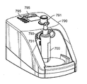
의료기기 회로의 다양한 부품들은 자연적 또는 인위적으로 가습된 가스를 환자에 전달하거나 환자로부터 배출시킨다. 예를 들어, 호흡기보호 시스템은 호흡기보호 장치를 포함함으로써 상기 장치를 통과하는 가스를 가온가습하여 환자의 편안함을 높이고/높이거나 환자의 호흡기 질환의 예후를 개선시킬 수 있다. 일부 호흡기보호 장치는 물 저장용기 및 상기 저장용기 안의 물을 가온시키기 위한 발열체를 포함할 수 있다. 물이 가온되면, 수증기가 형성되어, 호흡기보호 장치를 통과하는 가스 흐름에 합류될 수 있다. 일부 호흡기보호 장치는, 제어된 유량의 액체를 공급하기 위한 액체 유량 제어부, 및 가스 통로 내 위치하여 상기 통로를 통과하는 가스의 습도를 조절하도록 구성된 발열 표면을 구비하는 가온 시스템을 포함할 수 있다.The various components of the medical device circuit deliver naturally or artificially humidified gases to or discharge from the patient. For example, the respiratory protection system may include a respiratory protection device to heat and humidify the gas passing through the device to increase patient comfort and/or improve the prognosis of a patient's respiratory disease. Some respiratory protection devices may include a water storage container and a heating element for warming the water in the storage container. When the water warms, water vapor is formed, which can join the gas stream through the respiratory protection device. Some respiratory protection devices may include a liquid flow control unit for supplying a controlled flow rate of liquid, and a heating system having a heating surface located in the gas passage and configured to control the humidity of the gas passing through the passage.
일부 실시양태는 고온(elevated temperature) 및/또는 다습(elevated humidity) 환경에 놓였을 때 몰딩 재료가 기판에서 층간박리(delamination)되는 현상을 방지 또는 지연시킬 수 있는 견고한 기판-몰딩 재료 계면을 갖는 성형체를 제공한다.Some embodiments are shaped bodies having a rigid substrate-molding material interface that can prevent or delay the phenomenon of delamination of the molding material from the substrate when placed in an elevated temperature and/or elevated humidity environment. Provides.
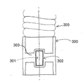
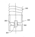
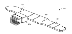
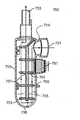
본원에 개시된 일부 실시양태는 가습 장치(예컨대, 호흡기보호용 가습 장치, 통기(insufflation) 장치 등)에 관한 것이다. 일부 실시양태에서, 가습 장치는 가스 유동 통로를 포함한다. 가스 유동 통로는 내부 영역 및 상기 내부 영역으로 가스를 유입시키도록 구성된 입구를 가질 수 있다. 가스 유동 통로는 가스가 가스 유동 통로의 내부 영역에서 나와 통과될 수 있도록 구성된 출구를 가질 수 있다. 일부 실시양태에서, 장치는 발열 표면을 갖는 히터를 포함한다. 히터는 가스 유동 통로의 입구와 출구 사이에 배치될 수 있다. 일부 구현예에서, 히터는 발열 표면에 수용된 가습용 액체를 가온함으로써, 가스 유동 통로를 통해 흐르는 가스가 가습되도록 구성된다. 특정 실시양태에서, 히터는 인쇄회로기판(PCB)을 포함한다. PCB는 발열 트랙들을 구비할 수 있다. PCB는 적어도 하나의 전기 컨택부를 가질 수 있다. 일부 실시양태에서, 전기 컨택부는 (예를 들어, 전기 공급원 등으로부터) 전기 신호를 송수신하도록 구성된다. 일부 실시양태에 의하면, 전기 컨택부는 전기 공급원으로부터 (예컨대, 전기 컨택부에 연결된 전기 도관을 통해) 전기를 받아서 PCB에 전원을 공급하도록 구성된다. 일부 실시양태에서, 전기 컨택부는 발열 트랙들과 전기적으로 소통한다. 일부 구현예에서, 히터는 PCB의 적어도 한 부분 위에 배치되는 몰딩 재료를 포함한다. 상기 몰딩 재료와 PCB의 한 부분이 규소-함유 링커를 포함한 접합층에 의해 접착될 수 있다. 일부 실시양태에 의하면, 접합층은 몰딩 재료의 적어도 일 부분을 PCB에 커플링 결합시킨다. 일부 구현예에서, 호흡기보호 장치는 가습된 가스를 환자에게 제공하도록 구성된다.Some embodiments disclosed herein relate to a humidifying device (eg, a humidifying device for respiratory protection, an insufflation device, etc.). In some embodiments, the humidification device includes a gas flow passage. The gas flow passage may have an inner region and an inlet configured to introduce gas into the inner region. The gas flow passage may have an outlet configured to allow gas to exit and pass through the inner region of the gas flow passage. In some embodiments, the device includes a heater having a heating surface. The heater may be disposed between the inlet and outlet of the gas flow passage. In some embodiments, the heater is configured to humidify the gas flowing through the gas flow passage by warming the humidifying liquid contained on the heating surface. In certain embodiments, the heater comprises a printed circuit board (PCB). The PCB may have heating tracks. The PCB may have at least one electrical contact. In some embodiments, the electrical contact portion is configured to transmit and receive electrical signals (eg, from an electrical source or the like). In some embodiments, the electrical contact portion is configured to receive electricity from an electrical source (eg, through an electrical conduit connected to the electrical contact portion) to supply power to the PCB. In some embodiments, the electrical contacts are in electrical communication with the heating tracks. In some embodiments, the heater includes a molding material disposed over at least a portion of the PCB. The molding material and a portion of the PCB may be bonded by a bonding layer comprising a silicon-containing linker. In some embodiments, the bonding layer couples at least a portion of the molding material to the PCB. In some embodiments, the respiratory protection device is configured to provide a humidified gas to the patient.
일부 실시양태에서, PCB는 내부 영역에서 가스 유동 통로의 외부 영역까지 가스 유동 통로의 일부에 걸쳐서 배치될 수 있다. PCB의 한 부분은 가스 유동 통로의 상기 외부 영역에 노출될 수 있는 반면, PCB의 다른 부분은 가스 유동 통로의 내부 영역과 서로 열이 연통될 수 있다. 일부 실시양태에서, PCB는 가스 유동 통로와 서로 열이 연통된다. 예를 들어, 일부 실시양태에 의하면, PCB는 가스 유동 통로로부터(예컨대, 가스 유동 챔버 내 가스로부터) 온도 정보를 수신하거나, (가스 유동 통로 내 가스(들)를 가온시키기 위한) 열 에너지를 가스 유동 통로로 전달하거나, 또는 둘 다 수행할 수 있다.In some embodiments, the PCB may be disposed over a portion of the gas flow passage from the inner region to the outer region of the gas flow passage. One part of the PCB may be exposed to the outer region of the gas flow passage, while the other part of the PCB may be in heat communication with the inner region of the gas flow passage. In some embodiments, the PCB is in heat communication with the gas flow passages. For example, in some embodiments, the PCB receives temperature information from the gas flow passage (e.g., from the gas in the gas flow chamber) or converts thermal energy (to warm the gas(s) in the gas flow passage). It can be delivered to the flow passage, or both.
특정 구현예에서, PCB는 호흡기보호 장치의 내부 영역의 상태에 관한 정보를 수신, 전송 및/또는 처리하도록 구성된 하나 이상의 전기 부품을 포함한다. 예를 들어, 일부 실시양태에 의하면, PCB는 장치 내의 하나 이상의 가스 관련 정보(예컨대, 온도, 압력, 및 습도 데이터)를 수신, 전송 및/또는 처리할 수 있다. 특정 구현예에서, PCB는 가스 유동 통로의 내부 영역의 상태에 관한 정보를 수신, 전송 및/또는 처리하도록 구성된 하나 이상의 전기 부품을 포함한다. PCB는 하나 이상의 센서를 포함할 수 있다. 일부 실시양태에 의하면, PCB는 가스 유동 통로의 내부 영역과 서로 열이 연통되는 하나 이상의 온도 센서를 포함할 수 있다. PCB는 2개 이상의 온도 센서를 포함할 수 있으며, 이들 온도 센서 중 적어도 하나는 발열 표면의 온도를 측정하도록 구성된다. PCB는 2개 이상의 온도 센서를 포함할 수 있으며, 이들 온도 센서 중 적어도 하나는 몰딩 재료의 표면 온도를 측정하도록 구성된다. 일부 실시양태에서, PCB는 발열 표면의 적어도 한 영역이 가습용 액체에 의해 습윤되었는지 여부를 검출하도록 구성된 온도 센서를 포함한다. 온도 센서(들)는 발열 표면에, 발열 표면 상에, 발열 표면 가까이에, 또는 발열 표면에 근접하여(proximal) 위치할 수 있다. 온도 센서(들)는 몰딩 재료에, 몰딩 재료 상에, 몰딩 재료 가까이에, 또는 몰딩 재료에 근접하여 위치할 수 있다. 일부 실시양태에서, PCB는 압력 센서, 유량 센서, 습도 센서, 또는 유체 레벨 센서 중 하나 이상을 포함한다. In certain embodiments, the PCB comprises one or more electrical components configured to receive, transmit, and/or process information regarding the condition of the internal area of the respiratory protection device. For example, according to some embodiments, the PCB may receive, transmit, and/or process one or more gas-related information (eg, temperature, pressure, and humidity data) within the device. In certain implementations, the PCB includes one or more electrical components configured to receive, transmit, and/or process information regarding the condition of the interior region of the gas flow passage. The PCB may contain one or more sensors. In some embodiments, the PCB may include one or more temperature sensors in heat communication with each other with an interior region of the gas flow passage. The PCB may include two or more temperature sensors, at least one of which is configured to measure the temperature of the heating surface. The PCB may include two or more temperature sensors, at least one of which is configured to measure the surface temperature of the molding material. In some embodiments, the PCB includes a temperature sensor configured to detect whether at least one area of the heating surface has been wetted by a humidifying liquid. The temperature sensor(s) may be located on the heating surface, on the heating surface, near the heating surface, or proximal to the heating surface. The temperature sensor(s) may be located in the molding material, on the molding material, near the molding material, or in proximity to the molding material. In some embodiments, the PCB includes one or more of a pressure sensor, a flow sensor, a humidity sensor, or a fluid level sensor.
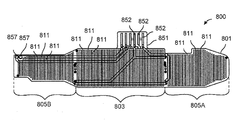
특정 실시양태에서, PCB의 발열 트랙은 가스 유동 통로의 내부 영역과 서로 열이 연통된다. PCB의 발열 트랙은 몰딩 재료로 커버될 수 있는 동시에, 몰딩 재료를 통과하는 가스 유동 통로의 내부 영역과 서로 열이 연통될 수 있다. 예를 들어, 발열 표면은 발열 트랙을 커버하고 있는 몰딩 재료의 일 부분을 포함하여 구성될 수 있다. 다른 실시양태에 의하면, 발열 표면은 발열 트랙들을 포함하고, 이들 발열 트랙(또는 그 일부)은 가스 유동 통로의 내부 영역에 직접 노출된다.In certain embodiments, the heating track of the PCB is in heat communication with each other with an interior region of the gas flow passage. The heating track of the PCB can be covered with the molding material, and at the same time, heat can be communicated with each other with the inner region of the gas flow passage through the molding material. For example, the heating surface may comprise a portion of the molding material covering the heating track. According to another embodiment, the heating surface comprises heating tracks, and these heating tracks (or portions thereof) are directly exposed to the inner region of the gas flow passage.
일부 실시양태에서, 몰딩 재료는 PCB의 전기 부품들 또는 센서들 중 하나 이상을 커버한다. 몰딩 재료는 이러한 전기 부품들 또는 센서들 중 하나 이상을 (예컨대, 몰딩 재료를 통과하는) 가스 유동 통로의 내부 영역으로부터 격리시켜 내부 영역으로의 직접 접촉을 피하도록 할 수 있다. 몰딩 재료는, 몰딩 재료를 통과하는 PCB의 전기 부품들 및/또는 센서들에 의해 가스 통로의 내부 영역을(예컨대, 그 내부에 있는 가스(들)의 온도, 압력, 습도, 2종 이상의 서로 다른 가스가 존재할 경우 가스들의 상대 비율 등을) 모니터링하는 것이 가능하도록 구성될 수 있다.In some embodiments, the molding material covers one or more of the electrical components or sensors of the PCB. The molding material may isolate one or more of these electrical components or sensors from the interior region of the gas flow passage (eg, passing through the molding material) to avoid direct contact to the interior region. The molding material is used to determine the internal area of the gas passage by means of electrical components and/or sensors of the PCB passing through the molding material (e.g., temperature, pressure, humidity, two or more different types of gas(s) therein). It may be configured to be able to monitor the relative proportions of the gases, etc.) if gas is present.
일부 실시양태에서, 가습 장치는 보관부(reservoir)로부터의 가습용 액체를 히터에 전달하기 위한 가습용 액체 주입구를 포함한다. 일부 실시양태에서, 가습 장치는 보관부로부터의 가습용 액체를 히터의 발열 표면에 전달하기 위한 가습용 액체 주입구를 포함한다. 일부 실시양태에 의하면, 상기 주입구는 가습용 액체(예컨대, 물)을 발열 표면에 적하하도록 구성된다. 일부 실시양태에서, 주입구는 가습용 액체를 장치의 어느 한 표면(예컨대, 장치의 벽, 홈통(trough), 경사로(ramp) 등) 상에 전달하도록 구성되며, 이때 상기 표면은 가습용 액체를 발열 표면 쪽으로 방향을 유도한다. 일부 실시양태에서, 가습 장치는 가습용 액체 예열기를 포함한다. 일부 실시양태에서, 호흡기보호용 가습 장치는 가습용 액체 유량 제어부를 포함한다. 일부 실시양태에서, 액체 유량 제어부는 계량 시스템 및/또는 펌프를 포함한다. 일부 실시양태에서, 가습 장치는 가스 예열기를 포함한다.In some embodiments, the humidification device includes a humidification liquid inlet for delivering the humidification liquid from the reservoir to the heater. In some embodiments, the humidification device includes a humidification liquid inlet for delivering the humidification liquid from the storage to the heating surface of the heater. In some embodiments, the inlet is configured to drip a humidifying liquid (eg, water) onto the heating surface. In some embodiments, the inlet is configured to deliver the humidification liquid onto any one surface of the device (e.g., the wall of the device, trough, ramp, etc.), wherein the surface heats the humidification liquid. Directs the direction towards the surface. In some embodiments, the humidification device includes a humidifying liquid preheater. In some embodiments, the respiratory protection humidifying device includes a humidifying liquid flow control. In some embodiments, the liquid flow control comprises a metering system and/or a pump. In some embodiments, the humidification device includes a gas preheater.
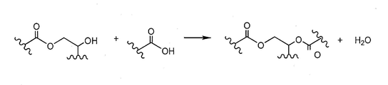
특정 구현예에서, 몰딩 재료는 열가소성 재료 및/또는 열경화성 재료를 포함한다. 특정 구현예에서, 몰딩 재료는 열가소성 재료를 포함한다. 특정 구현예에서, 몰딩 재료는 열경화성 재료를 포함한다. 일부 실시양태에 의하면, 몰딩 재료는 사출 성형된 열가소성 재료를 포함한다. 일부 실시양태에서, 몰딩 재료는 오버몰딩된 열가소성 재료를 포함한다. 일부 실시양태에서, 히터는 PCB 둘레에 열가소성 재료를 오버몰딩함으로써 형성된다. 일부 실시양태에서, 히터는 PCB 둘레에 열가소성 재료를 사출 성형함으로써 형성된다. 일부 실시양태에서, 히터는 PCB 둘레에 열가소성 재료를 인서트 몰딩함으로써 형성된다. 일부 실시양태에 의하면, 열가소성 재료는 에틸렌/메타크릴산 공중합체, 프로필렌/메타크릴산 공중합체, 에틸렌/메타크릴산/아크릴레이트 삼원 공중합체, 프로필렌/메타크릴산/아크릴레이트 삼원 공중합체, 에틸렌/아크릴레이트 공중합체, 프로필렌/아크릴레이트 공중합체, 숙신산 무수물이 그래프트된 폴리프로필렌, 숙신산 무수물이 그래프트된 폴리에틸렌, 폴리우레탄, 폴리아미드, 에틸렌/부틸 아크릴레이트/글리시딜 메타크릴레이트 삼원 공중합체, 프로필렌/부틸 아크릴레이트/글리시딜 메타크릴레이트 삼원 공중합체, 에틸렌/글리시딜 메타크릴레이트 공중합체, 프로필렌/글리시딜 메타크릴레이트 공중합체, 가교(crosslinkable) 폴리에틸렌, 가교 폴리프로필렌, 가교 폴리올레핀, 및 이들의 조합물로 구성된 군에서 선택된다. 일부 실시양태에서, 몰딩 재료는 열경화성 재료를 포함한다. 일부 실시양태에 의하면, 열경화성 재료는 실리콘 고무, 에폭시, 또는 폴리우레탄 중 1종 이상을 포함한다.In certain embodiments, the molding material comprises a thermoplastic material and/or a thermoset material. In certain embodiments, the molding material comprises a thermoplastic material. In certain embodiments, the molding material comprises a thermosetting material. In some embodiments, the molding material comprises an injection molded thermoplastic material. In some embodiments, the molding material comprises an overmolded thermoplastic material. In some embodiments, the heater is formed by overmolding a thermoplastic material around the PCB. In some embodiments, the heater is formed by injection molding a thermoplastic material around the PCB. In some embodiments, the heater is formed by insert molding a thermoplastic material around the PCB. In some embodiments, the thermoplastic material is an ethylene/methacrylic acid copolymer, a propylene/methacrylic acid copolymer, an ethylene/methacrylic acid/acrylate terpolymer, a propylene/methacrylic acid/acrylate terpolymer, ethylene. /Acrylate copolymer, propylene/acrylate copolymer, polypropylene grafted with succinic anhydride, polyethylene grafted with succinic anhydride, polyurethane, polyamide, ethylene/butyl acrylate/glycidyl methacrylate terpolymer, Propylene/butyl acrylate/glycidyl methacrylate terpolymer, ethylene/glycidyl methacrylate copolymer, propylene/glycidyl methacrylate copolymer, crosslinkable polyethylene, crosslinked polypropylene, crosslinked polyolefin , And a combination thereof. In some embodiments, the molding material comprises a thermosetting material. In some embodiments, the thermosetting material comprises one or more of silicone rubber, epoxy, or polyurethane.
일부 실시양태에서, 몰딩 재료는 PCB의 적어도 한 부분을 봉입(encapsulate)한다. 일부 실시양태에서, 몰딩 재료로 봉입된 PCB 부분에는 발열 트랙들 중 일부가 포함된다. 일부 실시양태에서, PCB는 가스 유동 통로의 내부 영역에 노출되지 않도록 봉입된다. 일부 실시양태에서, 몰딩 재료는 PCB가 가스 유동 통로의 내부 영역에 관한 정보(온도, 습도, 가스 유량 등)를 수집 및/또는 분배할 수 있게 하는 한편, PCB를 상기 통로의 내부 영역으로부터 물리적으로 차단시킨다. 일부 실시양태에 의하면, 봉입된 PCB에는 몰딩 재료로 커버되지 않는 부분(예컨대, 가스 유동 통로의 외부에 있는 PCB 부분)이 있어, PCB와 (예컨대, 전기 배선/도관 등으로) 컨택이 가능한다. 일부 실시양태에서, 몰딩 재료는 PCB와 가스 유동 통로 사이에 장벽(barrier)을 제공한다. 일부 실시양태에서, 몰딩 재료는 PCB를 가스 유동 통로의 내부 영역으로부터 완전히 격리시키는 효과를 제공한다. 일부 실시양태에서, PCB의 적어도 하나의 전기 컨택부는 몰딩 재료로 봉입 및/또는 커버되지 않는다.In some embodiments, the molding material encapsulates at least a portion of the PCB. In some embodiments, the portion of the PCB enclosed with a molding material includes some of the heating tracks. In some embodiments, the PCB is encapsulated so that it is not exposed to the interior region of the gas flow passage. In some embodiments, the molding material enables the PCB to collect and/or distribute information about the interior regions of the gas flow passage (temperature, humidity, gas flow, etc.), while physically displacing the PCB from the inner regions of the passage. Block it. In some embodiments, the encapsulated PCB has a portion that is not covered with a molding material (e.g., a portion of the PCB outside the gas flow passage), allowing contact with the PCB (e.g., by electrical wiring/conduit, etc.). In some embodiments, the molding material provides a barrier between the PCB and the gas flow passage. In some embodiments, the molding material provides the effect of completely isolating the PCB from the interior regions of the gas flow passage. In some embodiments, at least one electrical contact of the PCB is not encapsulated and/or covered with a molding material.
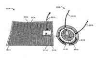
일부 실시양태에서, 몰딩 재료의 일 부분은 마이크로채널들 및/또는 표면 구조들을 포함한다. 일부 실시양태에서, 마이크로채널들 및/또는 표면 구조들은 발열 트랙에 의해 가온될 수 있는 가습용 액체를 수용, 분배, 및/또는 보유하도록 구성된다. 일부 실시양태에 의하면, 몰딩 재료의 일 부분이 가습용 액체를 수용하고 보유하도록 구성됨으로써, 상기 가습용 액체가 발열 트랙에 의해 가온될 수 있게 한다. 일부 실시양태에서, 가습용 액체를 수용하도록 구성된 몰딩 재료의 상기 부분은 접합층에 의해 PCB에 커플링 결합된다. 일부 실시양태에서, 몰딩 재료는 친수성이거나 소수성이다.In some embodiments, a portion of the molding material includes microchannels and/or surface structures. In some embodiments, the microchannels and/or surface structures are configured to contain, dispense, and/or hold a humidifying liquid that may be warmed by the heating track. In some embodiments, a portion of the molding material is configured to receive and hold the humidification liquid, thereby allowing the humidification liquid to be warmed by the heating track. In some embodiments, the portion of the molding material configured to receive the humidification liquid is coupled to the PCB by a bonding layer. In some embodiments, the molding material is hydrophilic or hydrophobic.
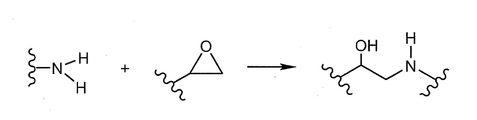
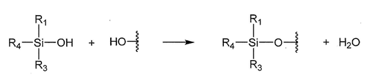
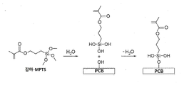
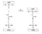
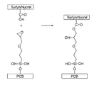
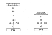
일부 실시양태에서, 접합층은 몰딩 재료를 기판의 일부(예컨대, PCB의 일부인 기판의 한 부분)에 화학적으로 커플링 결합시킨다. 일부 실시양태에서, 접합층은 열가소성 재료를 히터의 한 부분에 화학적으로 커플링 결합시킨다. 일부 실시양태에 의하면, 접합층은 몰딩 재료를 PCB의 한 부분에 연결시키는, 공유 결합, 수소 결합, 반데르발스 힘을 통한 결합 또는 이온 결합 중 하나 이상을 포함한다. 일부 실시양태에서, 접합층은 몰딩 재료 상의 치환기와 PCB 상의 치환기 사이의 공유 결합을 포함한다. 일부 실시양태에서, 접합층은 적어도 부분적으로는 에폭시 환 부분(moiety), 아민 부분, 숙신산 무수물 부분, 메톡실 부분 또는 에톡실 부분 중 하나 이상과 카복실 부분, 아민 부분, 에폭시 환 부분, 숙신산 무수물 부분 또는 반응성 실란 부분 중 하나 이상과의 반응을 통해 형성된다. 일부 실시양태에서, 접합층은 적어도 부분적으로는 숙신산 무수물 부분과 아민 부분과의 반응을 통해 형성된다. 일부 실시양태에서, 접합층은 적어도 부분적으로는 숙신산 무수물 부분과 2차 아민 부분과의 반응을 통해 형성된다.In some embodiments, the bonding layer chemically couples the molding material to a portion of the substrate (eg, a portion of the substrate that is part of the PCB). In some embodiments, the bonding layer chemically couples the thermoplastic material to a portion of the heater. In some embodiments, the bonding layer comprises one or more of covalent bonds, hydrogen bonds, bonds through Van der Waals forces, or ionic bonds that connect the molding material to a portion of the PCB. In some embodiments, the bonding layer includes a covalent bond between a substituent on the molding material and a substituent on the PCB. In some embodiments, the bonding layer is at least in part an epoxy ring moiety, an amine moiety, a succinic anhydride moiety, a methoxyl moiety or an ethoxy anhydride moiety with one or more of a carboxyl moiety, an amine moiety, an epoxy ring moiety, a succinic anhydride moiety Or through reaction with one or more of the reactive silane moieties. In some embodiments, the bonding layer is formed at least in part through reaction of the succinic anhydride moiety with the amine moiety. In some embodiments, the bonding layer is formed, at least in part, through reaction of a succinic anhydride moiety with a secondary amine moiety.
일부 구현예에서, 규소-함유 링커는:In some embodiments, the silicon-containing linker is:
<화학식 (L1)><Formula (L1)>

<화학식 (L2)><Formula (L2)>

으로 표시되는 실란 커플링 링커, 또는 이들의 중합된 형태의 실란 커플링 링커이며, 화학식에서, **는 몰딩 재료에 대한 부착 지점이고; 각각의 R'는 H, 할로겐, 하이드록실, C1-C8 알킬, C1-C8 알콕시, 및 ![]()
![]()
![]()
![]()
![]()
![]()

![]()
![]()

일부 실시양태에서, 규소-함유 링커는:In some embodiments, the silicon-containing linker is:
<화학식 (L3)><Formula (L3)>

<화학식 (L4)><Formula (L4)>

![]()
![]()
![]()
![]()
![]()
![]()
![]()
![]()
일부 실시양태에서, 규소-함유 링커는:In some embodiments, the silicon-containing linker is:
<화학식 (L5)><Formula (L5)>

<화학식 (L6)><Formula (L6)>

<화학식 (L7)><Formula (L7)>

<화학식 (L8)><Formula (L8)>

![]()
![]()
![]()
![]()
![]()
![]()

으로 구성된 군에서 선택되고; Z"는 H 또는 ![]()
![]()

![]()
![]()
![]()
![]()
![]()
![]()
![]()
![]()
![]()
![]()
![]()
![]()
![]()
![]()
![]()
![]()
일부 실시양태에서, 가습용 액체는 물을 포함한다.In some embodiments, the humidifying liquid comprises water.
일부 실시양태는 호흡기보호 시스템에 관한 것이다. 일부 실시양태에서, 호흡기보호 시스템은 가스(예컨대, 공기, 산소 등) 유량 공급원을 포함한다. 일부 실시양태에서, 호흡기보호 시스템은 전술된 또는 본원의 다른 부분에서도 기재된 가습 장치를 포함한다. 일부 실시양태에서, 호흡기보호 시스템은 흡기 튜브를 포함한다. 일부 실시양태에서, 호흡기보호 시스템은 환자 인터페이스를 포함한다. 일부 실시양태에서, 가스 유량 공급원은 고유량 요법을 제공하도록 구성된다. 일부 실시양태에서, 상기 시스템은 약 2 L/분 내지 약 150 L/분 범위의 유량, 또는 본원의 다른 부분에서도 기재된 다른 유량을 공급한다.Some embodiments relate to respiratory protection systems. In some embodiments, the respiratory protection system includes a gas (eg, air, oxygen, etc.) flow source. In some embodiments, the respiratory protection system includes a humidification device described above or elsewhere herein. In some embodiments, the respiratory protection system includes an intake tube. In some embodiments, the respiratory protection system includes a patient interface. In some embodiments, the gas flow source is configured to provide high flow therapy. In some embodiments, the system supplies a flow rate in the range of about 2 L/min to about 150 L/min, or other flow rates described elsewhere herein.
일부 실시양태는 호흡기보호 시스템 또는 의료용 통기 시스템에 사용되는 부품에 관한 것이다. 일부 실시양태에서, 부품은 전도성 트랙들 및 상기 전도성 트랙들이 상면에 배치된 기판을 포함한다. 일부 실시양태에서, 부품은 전자 부품의 적어도 한 부분 위로 성형되는 몰딩 재료를 포함한다. 일부 실시양태에서, 부품은 몰딩 재료를 상기 전자 부품의 적어도 한 부분과 커플링 결합시키는 접합층을 포함한다. 일부 실시양태에 의하면, 접합층은 규소-함유 링커를 포함한다.Some embodiments relate to parts for use in a respiratory protection system or a medical ventilation system. In some embodiments, the component includes conductive tracks and a substrate on which the conductive tracks are disposed. In some embodiments, the component includes a molding material that is molded over at least a portion of the electronic component. In some embodiments, a component includes a bonding layer that couples a molding material to at least a portion of the electronic component. In some embodiments, the bonding layer comprises a silicon-containing linker.
일부 실시양태에서, 접합층은 몰딩 재료와 전자 부품과는 별개의 층이다. 일부 실시양태에서, 접합층은 몰딩 재료에 공유 결합된 현수기 및 이와 매우 유사한, 전자 부품에 공유 결합된 현수기를 포함한다. 일부 실시양태에서, 기판(예컨대, 전기 부품)으로부터의 현수기는 몰딩 재료의 현수기에 공유결합으로 연결되거나 연결되지 않을 수 있다. 일부 실시양태에서, 접합층은 몰딩 재료를 전자 부품의 상기 부분에 화학적으로 커플링 결합시킨다. 일부 실시양태에서, 접합층은 몰딩 재료를 전자 부품의 한 부분에 연결시키는 결합으로서, 공유 결합, 수소 결합, 반데르발스 힘을 통한 결합 또는 이온 결합 중 하나 이상을 포함한다. 일부 실시양태에서, 접합층은 몰딩 재료와 기판(예컨대, 전자 부품)을 물리적으로 커플링시킨다.In some embodiments, the bonding layer is a separate layer from the molding material and the electronic component. In some embodiments, the bonding layer comprises a suspension covalently bonded to the molding material and a suspension covalently bonded to an electronic component, very similar to the one. In some embodiments, the suspension from the substrate (eg, electrical component) may or may not be covalently connected to the suspension of the molding material. In some embodiments, the bonding layer chemically couples the molding material to the portion of the electronic component. In some embodiments, the bonding layer is a bond that connects the molding material to a portion of the electronic component and includes one or more of covalent bonds, hydrogen bonds, bonds through Van der Waals forces, or ionic bonds. In some embodiments, the bonding layer physically couples the molding material and the substrate (eg, electronic component).
일부 실시양태에서, 접합층은 에폭시 환 부분, 아민 부분, 숙신산 무수물 부분, 메톡실 부분 또는 에톡실 부분 중 하나 이상과 카복실 부분, 아민 부분, 에폭시 환 부분, 숙신산 무수물 부분 또는 반응성 실란 부분 중 하나 이상과의 반응을 통해 형성된다. 일부 실시양태에서, 접합층은 숙신산 무수물 부분과 아민 부분과의 반응을 통해 형성된다. 일부 실시양태에서, 숙신산 무수물 부분은 전자 부품에 의해 제공되고, 아민 부분은 몰딩 재료에 의해 제공된다. 일부 실시양태에 의하면, 전자 부품과 숙신산 무수물 부분이 몰딩 재료에 의해 제공된다. 일부 실시양태에서, 접합층은 숙신산 무수물 부분과 2차 아민 부분과의 반응으로부터 형성된다. 일부 실시양태에 의하면, 숙신산 무수물 부분은 전자 부품에 의해 제공되고, 2차 아민 부분은 몰딩 재료에 의해 제공된다. 일부 실시양태에서는, 2차 아민 부분이 전자 부품에 의해 제공되고, 숙신산 무수물 부분이 몰딩 재료에 의해 제공된다.In some embodiments, the bonding layer comprises at least one of an epoxy ring moiety, an amine moiety, a succinic anhydride moiety, a methoxyl moiety or an ethoxyl moiety and at least one of a carboxyl moiety, an amine moiety, an epoxy ring moiety, a succinic anhydride moiety or a reactive silane moiety. It is formed through reaction with In some embodiments, the bonding layer is formed through reaction of a succinic anhydride moiety with an amine moiety. In some embodiments, the succinic anhydride moiety is provided by an electronic component and the amine moiety is provided by a molding material. In some embodiments, the electronic component and the succinic anhydride moiety are provided by a molding material. In some embodiments, the bonding layer is formed from the reaction of a succinic anhydride moiety with a secondary amine moiety. In some embodiments, the succinic anhydride moiety is provided by an electronic component and the secondary amine moiety is provided by a molding material. In some embodiments, the secondary amine moiety is provided by the electronic component and the succinic anhydride moiety is provided by the molding material.
일부 구현예에서, 규소-함유 링커는:In some embodiments, the silicon-containing linker is:
<화학식 (L1)><Formula (L1)>

<화학식 (L2)><Formula (L2)>

으로 표시되는 실란 커플링 링커, 또는 이들의 중합된 형태의 실란 커플링 링커이며, 화학식에서, **는 몰딩 재료에 대한 부착 지점이고; 각각의 R'는 H, 할로겐, 하이드록실, C1-C8 알킬, C1-C8 알콕시, 및 ![]()
![]()
![]()
![]()
![]()
![]()

![]()
![]()

일부 실시양태에서, 규소-함유 링커는:In some embodiments, the silicon-containing linker is:
<화학식 (L3)><Formula (L3)>

<화학식 (L4)><Formula (L4)>

![]()
![]()
![]()
![]()
![]()
![]()
![]()
![]()
일부 실시양태에서, 규소-함유 링커는:In some embodiments, the silicon-containing linker is:
<화학식 (L5)><Formula (L5)>

<화학식 (L6)><Formula (L6)>

<화학식 (L7)><Formula (L7)>

<화학식 (L8)><Formula (L8)>

![]()
![]()
![]()
![]()
![]()
![]()

으로 구성된 군에서 선택되고; Z"는 H 또는 ![]()
![]()

![]()
![]()
![]()
![]()
![]()
![]()
![]()
![]()
![]()
![]()
![]()
![]()
![]()
![]()
![]()
![]()
일부 실시양태에서, 전자 부품은 인쇄회로기판(PCB)이다. 일부 실시양태에 의하면, PCB는 강성 또는 연성이다.In some embodiments, the electronic component is a printed circuit board (PCB). In some embodiments, the PCB is rigid or flexible.
일부 실시양태에서, 전자 부품은 실리콘 고무, 세라믹, 금속, 유리 섬유, 화이버글래스, 사이징 처리된 화이버글래스, 에칭 호일, 충진 중합체, 에폭시 수지, 페놀 포름 알데하이드 수지, 종이 혹은 폴리에스테르 수지, 폴리에스테르, 폴리에테르이미드, 폴리이미드, 에폭시, 폴리에틸렌, 구리, 잉크, 또는 이들의 조합물을 포함한다. In some embodiments, the electronic component is silicone rubber, ceramic, metal, glass fiber, fiberglass, sized fiberglass, etching foil, filling polymer, epoxy resin, phenol formaldehyde resin, paper or polyester resin, polyester, Polyetherimide, polyimide, epoxy, polyethylene, copper, ink, or combinations thereof.
일부 실시양태에서, 몰딩 재료가 제공된 전자 부품 부분은 호흡기보호 시스템 내에서 열과 습도에 노출된다.In some embodiments, the electronic component portion provided with the molding material is exposed to heat and humidity within the respiratory protection system.
일부 실시양태에서, 몰딩 재료는 열가소성 재료 또는 열경화성 재료를 포함한다. 일부 실시양태에 의하면, 열가소성 재료가 사용된다. 일부 실시양태에서, 열가소성 재료는 에틸렌/메타크릴산 공중합체, 프로필렌/메타크릴산 공중합체, 에틸렌/메타크릴산/아크릴레이트 삼원 공중합체, 프로필렌/메타크릴산/아크릴레이트 삼원 공중합체, 에틸렌/아크릴레이트 공중합체, 프로필렌/아크릴레이트 공중합체, 숙신산 무수물이 그래프트된 폴리프로필렌, 숙신산 무수물이 그래프트된 폴리에틸렌, 폴리우레탄, 폴리아미드, 에틸렌/부틸 아크릴레이트/글리시딜 메타크릴레이트 삼원 공중합체, 프로필렌/부틸 아크릴레이트/글리시딜 메타크릴레이트 삼원 공중합체, 에틸렌/글리시딜 메타크릴레이트 공중합체, 프로필렌/글리시딜 메타크릴레이트 공중합체, 가교 폴리에틸렌, 가교 폴리프로필렌, 가교 폴리올레핀, 및 이들의 조합물로 구성된 군에서 선택된다. 일부 실시양태에서, 열가소성 재료는 오버몰딩된 열가소성 재료를 포함한다. 일부 실시양태에서, 부품은 전자 부품 둘레에 열가소성 재료를 사출 성형함으로써 형성된다. 일부 실시양태에서, 부품은 전자 부품 둘레에 열가소성 재료를 오버몰딩함으로써 형성된다. 일부 실시양태에서, 부품은 전자 부품 둘레에 열가소성 재료를 인서트 몰딩함으로써 형성된다. 일부 실시양태에 의하면, 열경화성 재료가 사용된다. 일부 실시양태에서, 몰딩 재료는 열경화성 중합체를 포함한다. 일부 실시양태에서, 열경화성 재료는 실리콘 고무, 에폭시 또는 폴리우레탄 중 1종 이상을 포함한다.In some embodiments, the molding material comprises a thermoplastic material or a thermoset material. In some embodiments, a thermoplastic material is used. In some embodiments, the thermoplastic material is an ethylene/methacrylic acid copolymer, a propylene/methacrylic acid copolymer, an ethylene/methacrylic acid/acrylate terpolymer, a propylene/methacrylic acid/acrylate terpolymer, ethylene/ Acrylate copolymer, propylene/acrylate copolymer, polypropylene grafted with succinic anhydride, polyethylene grafted with succinic anhydride, polyurethane, polyamide, ethylene/butyl acrylate/glycidyl methacrylate terpolymer, propylene /Butyl acrylate/glycidyl methacrylate terpolymer, ethylene/glycidyl methacrylate copolymer, propylene/glycidyl methacrylate copolymer, crosslinked polyethylene, crosslinked polypropylene, crosslinked polyolefin, and their It is selected from the group consisting of combinations. In some embodiments, the thermoplastic material comprises an overmolded thermoplastic material. In some embodiments, the part is formed by injection molding a thermoplastic material around the electronic component. In some embodiments, the component is formed by overmolding a thermoplastic material around the electronic component. In some embodiments, the component is formed by insert molding a thermoplastic material around the electronic component. In some embodiments, thermosetting materials are used. In some embodiments, the molding material comprises a thermosetting polymer. In some embodiments, the thermosetting material comprises one or more of silicone rubber, epoxy, or polyurethane.
일부 실시양태에서, 몰딩 재료는 표면 상에 마이크로채널들 및/또는 구조적 특징부들을 포함한다. 일부 실시양태에서, 마이크로채널들 및/또는 구조적 특징부들은 가습용 액체를 수용, 분배, 및/또는 보유하도록 구성된다. 일부 실시양태에서, 몰딩 재료는 친수성이거나 소수성이다.In some embodiments, the molding material includes microchannels and/or structural features on a surface. In some embodiments, the microchannels and/or structural features are configured to receive, dispense, and/or hold a humidifying liquid. In some embodiments, the molding material is hydrophilic or hydrophobic.
일부 실시양태에서, 전자 부품은 하나 이상의 센서를 포함한다. 일부 실시양태에서, 상기 하나 이상의 센서는 온도 센서, 압력 센서, 유량 센서, 습도 센서 또는 유체 레벨 센서 중 하나 이상을 포함한다. 일부 실시양태에서, 상기 하나 이상의 센서는 온도 센서, 압력 센서, 유량 센서 또는 습도 센서 중 하나 이상을 포함하되, 압력 센서, 유량 센서 또는 습도 센서 중 하나 이상은 가스 유동 통로 내 가스의 매개변수들을 검출하도록 구성된다. 일부 실시양태에 의하면, PCB는 유체 레벨 센서 및/또는 액체 센서를 포함한다. 일부 실시양태에서, 몰딩 재료는 센서(들)을 커버한다.In some embodiments, the electronic component includes one or more sensors. In some embodiments, the one or more sensors comprise one or more of a temperature sensor, a pressure sensor, a flow sensor, a humidity sensor, or a fluid level sensor. In some embodiments, the at least one sensor comprises at least one of a temperature sensor, a pressure sensor, a flow sensor, or a humidity sensor, wherein at least one of the pressure sensor, flow sensor or humidity sensor detects parameters of the gas in the gas flow passage. Is configured to In some embodiments, the PCB comprises a fluid level sensor and/or a liquid sensor. In some embodiments, the molding material covers the sensor(s).
일부 실시양태에서, 부품은, 필터용 하우징, 가스 도관, 챔버, 흡기 튜브, 튜브 커넥터, 튜브 조인트, 튜브 엘보, 발열체, 물 투입(dosing) 부품 또는 환자 인터페이스 부품 중 하나 이상을 추가로 포함하는 호흡기보호 시스템의 일부이다. 일부 실시양태에서, 전자 부품은 전기 컨택부를 포함한다. 일부 실시양태에서, 사용 시 부품은 주변환경에 비해 더 높은 온도 및/또는 습도에 노출된다. 일부 실시양태에서, 부품은 가습 챔버를 추가로 포함한다.In some embodiments, the part further comprises one or more of a housing for a filter, a gas conduit, a chamber, an intake tube, a tube connector, a tube joint, a tube elbow, a heating element, a water dosing part, or a patient interface part. It is part of the protection system. In some embodiments, the electronic component includes electrical contacts. In some embodiments, in use, the part is exposed to higher temperatures and/or humidity compared to its surroundings. In some embodiments, the component further comprises a humidification chamber.
일부 실시양태는 전술된 부품을 포함하는 호흡기보호 장치 또는 의료용 통기 장치에 관한 것이다. 일부 실시양태에서, 호흡기보호 장치 또는 의료용 통기 장치는 가습 챔버를 추가로 포함한다.Some embodiments relate to a respiratory protection device or medical ventilation device comprising the components described above. In some embodiments, the respiratory protection device or medical ventilation device further comprises a humidification chamber.
일부 실시양태는 가습 챔버를 위한 히터에 관한 것이다. 일부 실시양태에서, 히터는, 발열 트랙들 및 상기 발열 트랙들을 상면에 구비한 기판을 포함하여 구성된 발열 부품을 포함한다. 일부 실시양태에서, 히터는 상기 발열 부품의 적어도 한 부분에 배치되는 몰딩 재료를 포함한다. 일부 실시양태에서, 히터는 몰딩 재료의 적어도 일 부분을 발열 부품에 커플링 결합시키는 접합층을 포함한다. 일부 실시양태에서, 히터는, 발열 부품 상에 배치된 몰딩 재료의 위치에서 몰딩 재료를 발열 부품에 커플링 결합시키는 접합층을 포함한다. 일부 실시양태에 의하면, 접합층은 규소-함유 링커를 포함한다.Some embodiments relate to heaters for humidification chambers. In some embodiments, the heater includes a heating component configured to include heating tracks and a substrate having the heating tracks on an upper surface. In some embodiments, the heater includes a molding material disposed on at least a portion of the heating component. In some embodiments, the heater includes a bonding layer that couples at least a portion of the molding material to the heating component. In some embodiments, the heater includes a bonding layer that couples the molding material to the heating component at the location of the molding material disposed on the heating component. In some embodiments, the bonding layer comprises a silicon-containing linker.
일부 실시양태에서, 접합층은 몰딩 재료와 전자 부품과는 별개의 층이다. 일부 실시양태에서, 접합층은 몰딩 재료에 공유 결합된 현수기 및 매우 유사한, 전자 부품에 공유 결합된 현수기를 포함한다. 일부 실시양태에서, 접합층은 몰딩 재료를 발열 부품의 상기 부분에 화학적으로 커플링 결합시킨다. 일부 실시양태에서, 접합층은 몰딩 재료를 발열 부품의 상기 부분에 연결시키는 결합으로서, 공유 결합, 수소 결합, 반데르발스 힘을 통한 결합 또는 이온 결합 중 하나 이상을 포함한다. 일부 실시양태에서, 접합층은 에폭시 환 부분, 아민 부분, 숙신산 무수물 부분, 메톡실 부분 또는 에톡실 부분 중 하나 이상과 카복실 부분, 아민 부분, 에폭시 환 부분, 숙신산 무수물 부분 또는 반응성 실란 부분 중 하나 이상과의 반응을 통해 형성된다. 일부 실시양태에서, 접합층은 적어도 부분적으로는 숙신산 무수물 부분과 아민 부분과의 반응을 통해 형성된다. 일부 실시양태에서, 접합층은 적어도 부분적으로는 숙신산 무수물 부분과 2차 아민 부분과의 반응을 통해 형성된다. In some embodiments, the bonding layer is a separate layer from the molding material and the electronic component. In some embodiments, the bonding layer comprises a suspension covalently bonded to the molding material and a suspension covalently bonded to an electronic component, very similar. In some embodiments, the bonding layer chemically couples the molding material to said portion of the heating component. In some embodiments, the bonding layer comprises one or more of covalent bonds, hydrogen bonds, van der Waals forces bonds, or ionic bonds as bonds connecting the molding material to said portion of the heating component. In some embodiments, the bonding layer comprises at least one of an epoxy ring moiety, an amine moiety, a succinic anhydride moiety, a methoxyl moiety or an ethoxyl moiety and at least one of a carboxyl moiety, an amine moiety, an epoxy ring moiety, a succinic anhydride moiety or a reactive silane moiety. It is formed through reaction with In some embodiments, the bonding layer is formed at least in part through reaction of the succinic anhydride moiety with the amine moiety. In some embodiments, the bonding layer is formed, at least in part, through reaction of a succinic anhydride moiety with a secondary amine moiety.
일부 구현예에서, 규소-함유 링커는:In some embodiments, the silicon-containing linker is:
<화학식 (L1)><Formula (L1)>

<화학식 (L2)><Formula (L2)>

으로 표시되는 실란 커플링 링커, 또는 이들의 중합된 형태의 실란 커플링 링커이며, 화학식에서, **는 몰딩 재료에 대한 부착 지점이고; 각각의 R'는 H, 할로겐, 하이드록실, C1-C8 알킬, C1-C8 알콕시, 및 ![]()
![]()
![]()
![]()
![]()
![]()

![]()
![]()

일부 실시양태에서, 규소-함유 링커는:In some embodiments, the silicon-containing linker is:
<화학식 (L3)><Formula (L3)>

<화학식 (L4)><Formula (L4)>

![]()
![]()
![]()
![]()
![]()
![]()
![]()
![]()
일부 실시양태에서, 규소-함유 링커는:In some embodiments, the silicon-containing linker is:
<화학식 (L5)><Formula (L5)>

<화학식 (L6)><Formula (L6)>

<화학식 (L7)><Formula (L7)>

<화학식 (L8)><Formula (L8)>

![]()
![]()
![]()
![]()
![]()
![]()

으로 구성된 군에서 선택되고; Z"는 H 또는 ![]()
![]()

![]()
![]()
![]()
![]()
![]()
![]()
![]()
![]()
![]()
![]()
![]()
![]()
![]()
![]()
![]()
![]()
일부 실시양태에서, 발열 부품은 인쇄회로기판(PCB)이다. 일부 실시양태에 의하면, 인쇄회로기판은 강성 또는 연성이다. 일부 실시양태에서, 기판은 실리콘 고무, 세라믹, 금속, 유리 섬유, 화이버글래스, 사이징 처리된 화이버글래스, 에칭 호일, 충진 중합체, 또는 이들의 조합물을 포함한다. 일부 실시양태에서, 몰딩 재료는 열가소성 재료 또는 열경화성 재료를 포함한다. 일부 실시양태에서, 열가소성 재료는 에틸렌/메타크릴산 공중합체, 프로필렌/메타크릴산 공중합체, 에틸렌/메타크릴산/아크릴레이트 삼원 공중합체, 프로필렌/메타크릴산/아크릴레이트 삼원 공중합체, 에틸렌/아크릴레이트 공중합체, 프로필렌/아크릴레이트 공중합체, 숙신산 무수물이 그래프트된 폴리프로필렌, 숙신산 무수물이 그래프트된 폴리에틸렌, 폴리우레탄, 폴리아미드, 에틸렌/부틸 아크릴레이트/글리시딜 메타크릴레이트 삼원 공중합체, 프로필렌/부틸 아크릴레이트/글리시딜 메타크릴레이트 삼원 공중합체, 에틸렌/글리시딜 메타크릴레이트 공중합체, 프로필렌/글리시딜 메타크릴레이트 공중합체, 가교 폴리에틸렌, 가교 폴리프로필렌, 가교 폴리올레핀, 및 이들의 조합물로 구성된 군에서 선택된다. 일부 실시양태에서, 열가소성 재료는 사출 성형된 열가소성 재료(예컨대, 오버몰딩된 열가소성 재료, 인서트 몰딩된 열가소성 재료 등)을 포함한다. 일부 실시양태에서, 히터는 발열 부품 둘레에 열가소성 재료를 사출 성형함으로써 형성된다. 일부 실시양태에서, 히터는 발열 부품 둘레에 열가소성 재료를 오버몰딩함으로써 형성된다. 일부 실시양태에서, 히터는 발열 부품 둘레에 열가소성 재료를 인서트 몰딩함으로써 형성된다. 일부 실시양태에 의하면, 열경화성 재료는 실리콘 고무, 에폭시 또는 폴리우레탄 중 1종 이상을 포함한다.In some embodiments, the heating component is a printed circuit board (PCB). In some embodiments, the printed circuit board is rigid or flexible. In some embodiments, the substrate comprises silicone rubber, ceramic, metal, glass fiber, fiberglass, sized fiberglass, etch foil, fill polymer, or combinations thereof. In some embodiments, the molding material comprises a thermoplastic material or a thermoset material. In some embodiments, the thermoplastic material is an ethylene/methacrylic acid copolymer, a propylene/methacrylic acid copolymer, an ethylene/methacrylic acid/acrylate terpolymer, a propylene/methacrylic acid/acrylate terpolymer, ethylene/ Acrylate copolymer, propylene/acrylate copolymer, polypropylene grafted with succinic anhydride, polyethylene grafted with succinic anhydride, polyurethane, polyamide, ethylene/butyl acrylate/glycidyl methacrylate terpolymer, propylene /Butyl acrylate/glycidyl methacrylate terpolymer, ethylene/glycidyl methacrylate copolymer, propylene/glycidyl methacrylate copolymer, crosslinked polyethylene, crosslinked polypropylene, crosslinked polyolefin, and their It is selected from the group consisting of combinations. In some embodiments, the thermoplastic material comprises an injection molded thermoplastic material (eg, an overmolded thermoplastic material, an insert molded thermoplastic material, etc.). In some embodiments, the heater is formed by injection molding a thermoplastic material around the heating part. In some embodiments, the heater is formed by overmolding a thermoplastic material around the heating part. In some embodiments, the heater is formed by insert molding a thermoplastic material around the heating part. In some embodiments, the thermosetting material comprises one or more of silicone rubber, epoxy, or polyurethane.
일부 실시양태에서, 몰딩 재료는 표면 상에 마이크로채널들 및/또는 구조적 특징부들을 포함한다. 일부 실시양태에서, 마이크로채널 또는 구조적 특징부는 가습용 액체를 보유하도록 구성된다. 일부 실시양태에서, 몰딩 재료는 친수성이거나 소수성이다.In some embodiments, the molding material includes microchannels and/or structural features on a surface. In some embodiments, the microchannels or structural features are configured to hold a humidifying liquid. In some embodiments, the molding material is hydrophilic or hydrophobic.
일부 실시양태에서, 발열 트랙은 발열 부품과 서로 열이 연통될 때 가습용 액체를 가온시키고 가습용 액체를 가스 유동 경로 내부로 증발시키도록 구성된다. 일부 실시양태에서, 발열 부품은 전기 커넥터를 포함한다.In some embodiments, the heating track is configured to warm the humidifying liquid and evaporate the humidifying liquid into the gas flow path when heat is in heat communication with the heating component. In some embodiments, the heating component includes an electrical connector.
일부 실시양태는 가습 챔버를 위한 히터에 관한 것이다. 일부 실시양태에서, 히터는 상면에 발열 트랙들을 구비한 기판을 포함하여 구성된 발열 부품을 포함한다. 일부 실시양태에서, 히터는 발열 부품을 봉입하는 몰딩 재료를 포함하며, 이로써 발열 부품은 몰딩 재료에 의해 가습 챔버의 내부 영역으로부터 격리된다. 일부 실시양태에서, 히터는 몰딩 재료를 발열 부품에 커플링 결합시키는 접합층을 포함한다.Some embodiments relate to heaters for humidification chambers. In some embodiments, the heater includes a heating component configured including a substrate with heating tracks on a top surface. In some embodiments, the heater includes a molding material encapsulating the heating component, whereby the heating component is isolated from the interior area of the humidification chamber by the molding material. In some embodiments, the heater includes a bonding layer that couples the molding material to the heating component.
일부 실시양태에서, 접합층은 몰딩 재료와 발열 부품과는 별개의 층이다. 일부 실시양태에서, 접합층은 몰딩 재료에 공유 결합된 현수기 및 매우 유사한, 전자 부품에 공유 결합된 현수기를 포함한다. 일부 실시양태에서, 접합층은 규소-함유 링커층을 포함한다. 일부 실시양태에서, 접합층은 몰딩 재료를 전자 부품에 화학적으로 커플링 결합시킨다. 일부 실시양태에서, 접합층은 몰딩 재료를 발열 부품 부분에 연결시키는 결합으로서, 공유 결합, 수소 결합, 반데르발스 힘을 통한 결합 또는 이온 결합 중 하나 이상을 포함한다. 일부 실시양태에서, 접합층은 적어도 부분적으로는 에폭시 환 부분, 아민 부분, 숙신산 무수물 부분, 메톡실 부분 또는 에톡실 부분 중 하나 이상과 카복실 부분, 아민 부분, 에폭시 환 부분, 숙신산 무수물 부분 또는 반응성 실란 부분 중 하나 이상과의 반응을 통해 형성된다. 에폭시는, 적어도, 아민 또는 카복실과 화학반응을 일으킬 수 있다. 숙신산 무수물은, 적어도, 아민과 화학반응을 일으킬 수 있다. 아민은, 적어도, 카복실, 에폭시 환, 및 숙신산 무수물과 화학반응을 일으킬 수 있다. 에톡실 및 메톡실은 각각 실라놀과 화학반응을 일으킬 수 있다. 일부 실시양태에서, 접합층은 적어도 부분적으로는 숙신산 무수물 부분과 아민 부분 사이의 반응을 통해 형성된다. 일부 실시양태에서, 접합층은 적어도 부분적으로는 숙신산 무수물 부분과 2차 아민 부분 사이의 반응을 통해 형성된다. In some embodiments, the bonding layer is a separate layer from the molding material and the heating component. In some embodiments, the bonding layer comprises a suspension covalently bonded to the molding material and a suspension covalently bonded to an electronic component, very similar. In some embodiments, the bonding layer comprises a silicon-containing linker layer. In some embodiments, the bonding layer chemically couples the molding material to the electronic component. In some embodiments, the bonding layer comprises one or more of covalent bonds, hydrogen bonds, van der Waals forces bonds, or ionic bonds as bonds that connect the molding material to the heating component portion. In some embodiments, the bonding layer is at least partially an epoxy ring moiety, an amine moiety, a succinic anhydride moiety, a methoxyl moiety or an ethoxyl moiety with one or more of a carboxyl moiety, an amine moiety, an epoxy ring moiety, a succinic anhydride moiety or a reactive silane. It is formed through reaction with one or more of the parts. Epoxy can, at least, undergo a chemical reaction with amines or carboxyls. Succinic anhydride, at least, can cause a chemical reaction with an amine. The amine can cause a chemical reaction with, at least, carboxyl, epoxy ring, and succinic anhydride. Ethoxyl and methoxyl can react chemically with silanol, respectively. In some embodiments, the bonding layer is formed at least in part through a reaction between the succinic anhydride moiety and the amine moiety. In some embodiments, the bonding layer is formed at least in part through a reaction between the succinic anhydride moiety and the secondary amine moiety.
일부 구현예에서, 규소-함유 링커는:In some embodiments, the silicon-containing linker is:
<화학식 (L1)><Formula (L1)>

<화학식 (L2)><Formula (L2)>

으로 표시되는 실란 커플링 링커, 또는 이들의 중합된 형태의 실란 커플링 링커이며, 화학식에서, **는 몰딩 재료에 대한 부착 지점이고; 각각의 R'는 H, 할로겐, 하이드록실, C1-C8 알킬, C1-C8 알콕시, 및 ![]()
![]()
![]()
![]()
![]()
![]()

![]()
![]()

일부 실시양태에서, 규소-함유 링커는:In some embodiments, the silicon-containing linker is:
<화학식 (L3)><Formula (L3)>

<화학식 (L4)><Formula (L4)>

![]()
![]()
![]()
![]()
![]()
![]()
![]()
![]()
일부 실시양태에서, 규소-함유 링커는:In some embodiments, the silicon-containing linker is:
<화학식 (L5)><Formula (L5)>

<화학식 (L6)><Formula (L6)>

<화학식 (L7)><Formula (L7)>

<화학식 (L8)><Formula (L8)>

![]()
![]()
![]()
![]()
![]()
![]()

으로 구성된 군에서 선택되고; Z"는 H 또는 ![]()
![]()

![]()
![]()
![]()
![]()
![]()
![]()
![]()
![]()
![]()
![]()
![]()
![]()
![]()
![]()
![]()
![]()
일부 실시양태에서, 발열 부품은 인쇄회로기판(PCB)을 포함한다. 일부 실시양태에서, PCB 및/또는 PCB의 기판은 강성 또는 연성이다. 일부 실시양태에서, PCB 및/또는 PCB의 기판은 실리콘 고무, 세라믹, 금속, 유리 섬유, 화이버글래스, 사이징 처리된 화이버글래스, 에칭 호일, 충진 중합체, 에폭시 수지, 페놀 포름 알데하이드 수지, 종이 혹은 폴리에스테르 수지, 폴리에스테르, 폴리에테르이미드, 폴리이미드, 에폭시, 폴리에틸렌, 구리, 잉크, 또는 이들의 조합물을 포함한다. In some embodiments, the heating component comprises a printed circuit board (PCB). In some embodiments, the PCB and/or the substrate of the PCB is rigid or flexible. In some embodiments, the PCB and/or the substrate of the PCB is silicone rubber, ceramic, metal, glass fiber, fiberglass, sized fiberglass, etching foil, filling polymer, epoxy resin, phenol formaldehyde resin, paper or polyester. Resin, polyester, polyetherimide, polyimide, epoxy, polyethylene, copper, ink, or combinations thereof.
일부 실시양태에서, 몰딩 재료는 열가소성 재료 또는 열경화성 재료를 포함한다. 일부 실시양태에서, 열가소성 재료는 에틸렌/메타크릴산 공중합체, 프로필렌/메타크릴산 공중합체, 에틸렌/메타크릴산/아크릴레이트 삼원 공중합체, 프로필렌/메타크릴산/아크릴레이트 삼원 공중합체, 에틸렌/아크릴레이트 공중합체, 프로필렌/아크릴레이트 공중합체, 숙신산 무수물이 그래프트된 폴리프로필렌, 숙신산 무수물이 그래프트된 폴리에틸렌, 폴리우레탄, 폴리아미드, 에틸렌/부틸 아크릴레이트/글리시딜 메타크릴레이트 삼원 공중합체, 프로필렌/부틸 아크릴레이트/글리시딜 메타크릴레이트 삼원 공중합체, 에틸렌/글리시딜 메타크릴레이트 공중합체, 프로필렌/글리시딜 메타크릴레이트 공중합체, 가교 폴리에틸렌, 가교 폴리프로필렌, 가교 폴리올레핀, 및 이들의 조합물로 구성된 군에서 선택된다. In some embodiments, the molding material comprises a thermoplastic material or a thermoset material. In some embodiments, the thermoplastic material is an ethylene/methacrylic acid copolymer, a propylene/methacrylic acid copolymer, an ethylene/methacrylic acid/acrylate terpolymer, a propylene/methacrylic acid/acrylate terpolymer, ethylene/ Acrylate copolymer, propylene/acrylate copolymer, polypropylene grafted with succinic anhydride, polyethylene grafted with succinic anhydride, polyurethane, polyamide, ethylene/butyl acrylate/glycidyl methacrylate terpolymer, propylene /Butyl acrylate/glycidyl methacrylate terpolymer, ethylene/glycidyl methacrylate copolymer, propylene/glycidyl methacrylate copolymer, crosslinked polyethylene, crosslinked polypropylene, crosslinked polyolefin, and their It is selected from the group consisting of combinations.
일부 실시양태에서, 히터는 발열 부품 둘레에 열가소성 재료를 사출 성형함으로써 형성된다. 일부 실시양태에서, 히터는 발열 부품 둘레에 열가소성 재료를 오버몰딩함으로써 형성된다. 일부 실시양태에서, 히터는 발열 부품 둘레에 열가소성 재료를 인서트 몰딩함으로써 형성된다. 일부 실시양태에서, 열경화성 재료는 실리콘 고무, 에폭시 또는 폴리우레탄 중 1종 이상을 포함한다. 일부 실시양태에서, 몰딩 재료는 마이크로채널들 및/또는 구조적 특징부들을 포함한다. 일부 실시양태에서, 마이크로채널 및/또는 구조적 특징부는 가습용 액체를 보유하도록 구성된다. 일부 실시양태에서, 몰딩 재료는 친수성이거나 소수성이다.In some embodiments, the heater is formed by injection molding a thermoplastic material around the heating part. In some embodiments, the heater is formed by overmolding a thermoplastic material around the heating part. In some embodiments, the heater is formed by insert molding a thermoplastic material around the heating part. In some embodiments, the thermosetting material comprises one or more of silicone rubber, epoxy, or polyurethane. In some embodiments, the molding material includes microchannels and/or structural features. In some embodiments, the microchannels and/or structural features are configured to hold a humidifying liquid. In some embodiments, the molding material is hydrophilic or hydrophobic.
일부 실시양태에서, 발열 트랙은 발열 부품과 서로 열이 연통될 때 가습용 액체를 가온시키고 가습용 액체를 가스 유동 경로 내부로 증발시키도록 구성된다. 일부 실시양태에서, 발열 부품은 전기 커넥터를 포함한다.In some embodiments, the heating track is configured to warm the humidifying liquid and evaporate the humidifying liquid into the gas flow path when heat is in heat communication with the heating component. In some embodiments, the heating component includes an electrical connector.
일부 실시양태는 가스 공급원으로부터 가스를 공급받도록 하는 입구 및 가스를 환자에 전달되도록 하는 출구를 포함하는 가습 챔버에 관한 것으로, 상기 입구와 출구에 의해 가스 유동 경로가 획정된다. 일부 실시양태에 의하면, 가습 챔버는 전술된 또는 본원의 다른 부분에서도 기재된 히터를 포함한다. 일부 실시양태에서, 히터는 가스 유동 경로에 있으면서 가스를 가온가습하도록 구성된다. 일부 실시양태에서, 가습 챔버는 호흡기보호 시스템 또는 의료용 통기 시스템에서 사용하도록 구성된다.Some embodiments relate to a humidification chamber comprising an inlet for receiving gas from a gas source and an outlet for delivering gas to a patient, wherein a gas flow path is defined by the inlet and outlet. In some embodiments, the humidification chamber includes a heater described above or elsewhere herein. In some embodiments, the heater is configured to warm and humidify the gas while in the gas flow path. In some embodiments, the humidification chamber is configured for use in a respiratory protection system or a medical ventilation system.
일부 실시양태는 성형품에 관한 것이다. 일부 실시양태에서, 성형품은 열가소성 재료와 기판을 포함한다. 일부 실시양태에 의하면, 기판의 적어도 한 부분이 규소-함유 링커를 통해 열가소성 재료에 커플링 결합된다. 일부 실시양태에서, 규소-함유 링커는 적어도 부분적으로는 숙신산 무수물 부분과 아민 부분 사이의 반응을 통해 형성된다.Some embodiments relate to molded articles. In some embodiments, the shaped article includes a thermoplastic material and a substrate. In some embodiments, at least a portion of the substrate is coupled to the thermoplastic material through a silicon-containing linker. In some embodiments, the silicon-containing linker is formed, at least in part, through a reaction between the succinic anhydride moiety and the amine moiety.
일부 실시양태는 기판에 열가소성 재료를 커플링 결합시키는 방법에 관한 것이다. 일부 실시양태에서, 방법은 표면 상에 적어도 1종의 규소-함유 결합제(linking agent)가 부착된 기판을 제공하는 단계를 포함한다. 일부 실시양태에서, 방법은 부착된 규소-함유 결합제에 열가소성 재료를 접촉시켜 열가소성 재료와 기판 사이에 결합이 형성되도록 하는 단계를 포함한다. 일부 실시양태에서, 상기 결합은 숙신산 무수물 부분과 아민 부분 사이의 반응에서 수득되는 반응 생성물을 포함한다. 일부 실시양태에 의하면, 숙신산 무수물 부분이 규소-함유 링커에 제공된다. 일부 실시양태에 의하면, 아민 부분이 열가소성 재료에 제공된다. 일부 실시양태에 의하면, 아민 부분이 규소-함유 링커에 제공된다. 일부 실시양태에 의하면, 숙신산 무수물 부분이 열가소성 재료에 제공된다. 일부 실시양태에서, 아민 부분은 2차 아민 부분을 포함한다. 일부 실시양태에서, 표면 상에 적어도 1종의 규소-함유 결합제가 부착된 기판을 제공하는 단계는 표면 상에 하이드록실 및/또는 카복실을 포함하는 기판을 제공하는 단계와, 규소-함유 결합제를 기판 표면 상의 하이드록실 및/또는 카복실과 반응시키는 단계를 포함한다. 일부 실시양태에서, 규소-함유 결합제를 기판 상의 하이드록실 및/또는 카복실과 반응시키는 단계는 규소-함유 결합제를 가수분해하여 반응성 실라놀을 형성하는 단계와, 반응성 실라놀을 기판 상의 하이드록실 및/또는 카복실과 접촉시키는 단계를 포함한다. 일부 실시양태에서, 규소-함유 결합제를 기판 상의 하이드록실 및/또는 카복실과 반응시키는 단계는 플라즈마를 이용한 화학기상증착(PECVD)을 포함한다. 일부 실시양태에서, 표면 상에 하이드록실 및/또는 카복실을 포함하는 기판을 제공하는 단계는 플라즈마 처리, 코로나 방전, 오존 처리, 화학적 처리 또는 화염 처리를 통해 기판 표면을 활성화시키는 단계를 추가로 포함한다.Some embodiments relate to a method of coupling a thermoplastic material to a substrate. In some embodiments, the method includes providing a substrate having at least one silicon-containing linking agent attached thereto on the surface. In some embodiments, the method includes contacting the thermoplastic material with an attached silicon-containing binder such that a bond is formed between the thermoplastic material and the substrate. In some embodiments, the linkage comprises a reaction product obtained in the reaction between the succinic anhydride moiety and the amine moiety. In some embodiments, a succinic anhydride moiety is provided to the silicon-containing linker. In some embodiments, the amine moiety is provided in the thermoplastic material. In some embodiments, the amine moiety is provided to the silicon-containing linker. In some embodiments, a succinic anhydride moiety is provided in the thermoplastic material. In some embodiments, the amine moiety comprises a secondary amine moiety. In some embodiments, the step of providing a substrate with at least one silicon-containing binder attached thereon to the surface comprises providing a substrate comprising hydroxyl and/or carboxyl on the surface, and applying a silicon-containing binder to the substrate. And reacting with hydroxyl and/or carboxyl on the surface. In some embodiments, reacting the silicon-containing binder with hydroxyl and/or carboxyl on the substrate comprises hydrolyzing the silicon-containing binder to form reactive silanol, and the reactive silanol with hydroxyl and/or carboxyl on the substrate. Or contacting the carboxyl. In some embodiments, the step of reacting the silicon-containing binder with hydroxyl and/or carboxyl on the substrate comprises chemical vapor deposition (PECVD) with plasma. In some embodiments, providing a substrate comprising hydroxyl and/or carboxyl on the surface further comprises activating the substrate surface via plasma treatment, corona discharge, ozone treatment, chemical treatment, or flame treatment. .
일부 실시양태에서, 규소-함유 결합제는 실란 커플링제이다. 일부 실시양태에 의하면, 실란 커플링제는:In some embodiments, the silicon-containing binder is a silane coupling agent. In some embodiments, the silane coupling agent:
<화학식 (A1)><Formula (A1)>

<화학식 (A2)><Formula (A2)>

으로 표시되며, Is displayed as
화학식에서, R1, R2, R3, R4, R5 및 R6은 각각 독립적으로 H, 할로겐, 하이드록실, C1-C8 알킬 및 C1-C8 알콕시로 구성된 군에서 선택되되, 화학식 (A1)의 R1, R2 또는 R3 중 적어도 하나, 또는 화학식 (A2)의 R1, R2, R3, R4, R5 또는 R6 중 적어도 하나가 하이드록실 또는 C1-C8 알콕시이고; Y는 단일 결합이거나, C1-C8 알킬렌이거나, O 또는 N 중에서 선택된 1개 이상의 헤테로 원자를 함유한 C1-C8 헤테로알킬렌이고; X는 1차 아민, 2차 아민, 및 숙신산 무수물로 구성된 군에서 선택된다.In the formula, R 1 , R 2 , R 3 , R 4 , R 5 and R 6 are each independently selected from the group consisting of H, halogen, hydroxyl, C1-C8 alkyl and C1-C8 alkoxy, formula (A1 ) At least one of R 1 , R 2 or R 3 , or at least one of R 1 , R 2 , R 3 , R 4 , R 5 or R 6 of formula (A2) is hydroxyl or C1-C8 alkoxy; Y is a single bond, C1-C8 alkylene, or C1-C8 heteroalkylene containing at least one hetero atom selected from O or N; X is selected from the group consisting of primary amines, secondary amines, and succinic anhydride.
일부 실시양태에서, 실란 커플링제는 3-아미노프로필 트리메톡시실란(APTMS), 3-아미노프로필 트리에톡시실란(APTES), (3-트리에톡시실릴)프로필숙신산 무수물(TEPSA) 및 비스(3-트리메톡시실릴프로필)아민으로 구성된 군에서 선택된다. 일부 실시양태에서, 규소-함유 결합제는 실록산이다.In some embodiments, the silane coupling agent is 3-aminopropyl trimethoxysilane (APTMS), 3-aminopropyl triethoxysilane (APTES), (3-triethoxysilyl) propylsuccinic anhydride (TEPSA) and bis( It is selected from the group consisting of 3-trimethoxysilylpropyl)amine. In some embodiments, the silicon-containing binder is a siloxane.
일부 실시양태에서, 실란 커플링제는:In some embodiments, the silane coupling agent:
<화학식 (A5)><Formula (A5)>

<화학식 (A6)><Formula (A6)>

<화학식 (A7)><Formula (A7)>

<화학식 (A8)><Formula (A8)>

화학식에서, R1, R2, R3, R4, R5 및 R6은 각각 독립적으로 H, 할로겐, 하이드록실, C1-C8 알킬 및 C1-C8 알콕시로 구성된 군에서 선택되되, 화학식 (A5)의 R1, R2, R3, R4, 또는 R5 중 적어도 하나, 화학식 (A6)과 화학식 (A7)의 R1, R2, R3, R4, R5 또는 R6 중 적어도 하나, 그리고 화학식 (A8)의 R1 또는 R2 중 적어도 2개는 독립적으로 하이드록실 또는 C1-C8 알콕시이고; Y는 단일 결합이거나, C1-C8 알킬렌이거나, O 또는 N 중에서 선택된 1개 이상의 헤테로 원자를 함유한 C1-C8 헤테로알킬렌이고; Y'는 C1-C8 알킬이거나, O 또는 N 중에서 선택된 1개 이상의 헤테로 원자를 함유한 C1-C8 헤테로알킬이고; X는 에폭시, 1차 아민, 2차 아민, 및 숙신산 무수물로 구성된 군에서 선택되고; m은 1 이상의 정수이고; n은 1 이상의 정수이다. 일부 실시양태에서, 실록산은 아미노프로필 실세스퀴옥산, 아미노에틸 아미노프로필 실세스퀴옥산, 아미노프로필실세스퀴옥산-메틸실세스퀴옥산, 및 비관능성 실록산으로 구성된 군에서 선택된다.In the formula, R 1 , R 2 , R 3 , R 4 , R 5 and R 6 are each independently selected from the group consisting of H, halogen, hydroxyl, C1-C8 alkyl and C1-C8 alkoxy, formula (A5 ) Of at least one of R 1 , R 2 , R 3 , R 4 , or R 5 , at least of R 1 , R 2 , R 3 , R 4 , R 5 or R 6 of formula (A6) and formula (A7) One, and at least two of R 1 or R 2 of formula (A8) are independently hydroxyl or C1-C8 alkoxy; Y is a single bond, C1-C8 alkylene, or C1-C8 heteroalkylene containing at least one hetero atom selected from O or N; Y'is C1-C8 alkyl or C1-C8 heteroalkyl containing one or more heteroatoms selected from O or N; X is selected from the group consisting of epoxy, primary amine, secondary amine, and succinic anhydride; m is an integer greater than or equal to 1; n is an integer of 1 or more. In some embodiments, the siloxane is selected from the group consisting of aminopropyl silsesquioxane, aminoethyl aminopropyl silsesquioxane, aminopropylsilsesquioxane-methylsilsesquioxane, and nonfunctional siloxanes.
일부 실시양태에서, 기판은 인쇄회로기판(PCB)의 일부이다(예컨대, 한 부분을 구성함). 일부 실시양태에 의하면, PCB는 강성이다. 일부 실시양태에 의하면, PCB는 연성이다. 일부 실시양태에서, PCB는 하나 이상의 센서를 포함한다. 일부 실시양태에서, 상기 하나 이상의 센서는 온도 센서, 유량 센서, 압력 센서, 습도 센서 및 유체 레벨 센서로 구성된 군에서 선택된다. 일부 실시양태에 의하면, PCB는 발열 소자를 포함한다. 일부 실시양태에 의하면, PCB는 전기 커넥터를 포함한다.In some embodiments, the substrate is part of (eg, constitutes a part) a printed circuit board (PCB). In some embodiments, the PCB is rigid. In some embodiments, the PCB is flexible. In some embodiments, the PCB includes one or more sensors. In some embodiments, the one or more sensors are selected from the group consisting of a temperature sensor, a flow sensor, a pressure sensor, a humidity sensor, and a fluid level sensor. In some embodiments, the PCB comprises a heating element. In some embodiments, the PCB comprises an electrical connector.
일부 실시양태는 열경화성 재료와 기판을 구비한 성형품을 포함하는 호흡기보호 장치에 관한 것이다. 일부 실시양태에서, 기판의 적어도 한 부분은 규소-함유 링커를 통해 열경화성 재료에 커플링 결합된다. 일부 실시양태에서, 규소-함유 링커는:Some embodiments relate to a respiratory protection device comprising a molded article having a thermosetting material and a substrate. In some embodiments, at least a portion of the substrate is coupled to the thermosetting material through a silicon-containing linker. In some embodiments, the silicon-containing linker is:
<화학식 (L9)><Formula (L9)>

<화학식 (L10)><Formula (L10)>

![]()
![]()
![]()


![]()
![]()
![]()
일부 실시양태에서, 열경화성 재료는 -Si-H 부분을 포함한다. 일부 실시양태에 의하면, 열경화성 재료는 실리콘 고무이다. 일부 실시양태에서, 성형품은 필터용 하우징, 가스 도관, 챔버, 흡기 튜브, 튜브 커넥터, 튜브 조인트, 튜브 엘보, 발열체, 또는 환자 인터페이스 부품이다. 일부 실시양태에서, 열경화성 재료는 기판 상의 몰딩 재료이다. 일부 실시양태에서, 성형품은 기판 둘레에 몰딩 재료를 사출 성형함으로써 형성된다. 일부 실시양태에서, 성형품은 기판 둘레에 몰딩 재료를 인서트 몰딩함으로써 형성된다. 일부 실시양태에서, 성형품은 기판 둘레에 몰딩 재료를 오버몰딩함으로써 형성된다. 일부 실시양태에서, 몰딩 재료는 표면 상에 마이크로채널들 또는 구조들을 포함한다.In some embodiments, the thermosetting material comprises a -Si-H moiety. In some embodiments, the thermosetting material is silicone rubber. In some embodiments, the molded article is a housing for a filter, a gas conduit, a chamber, an intake tube, a tube connector, a tube joint, a tube elbow, a heating element, or a patient interface part. In some embodiments, the thermosetting material is a molding material on the substrate. In some embodiments, the molded article is formed by injection molding a molding material around a substrate. In some embodiments, the shaped article is formed by insert molding a molding material around a substrate. In some embodiments, the shaped article is formed by overmolding a molding material around a substrate. In some embodiments, the molding material includes microchannels or structures on the surface.
일부 실시양태에서, 기판은, 활성화되어 표면 상에 하이드록실기를 형성할 수 있는 재료를 포함한다. 일부 실시양태에 의하면, 기판은 실리콘 고무, 세라믹, 금속, 유리 섬유, 화이버글래스, 사이징 처리된 화이버글래스, 에칭 호일, 충진 중합체, 에폭시 수지, 페놀 포름 알데하이드 수지, 종이 혹은 폴리에스테르 수지, 폴리에스테르, 폴리에테르이미드, 폴리이미드, 에폭시, 폴리에틸렌, 구리, 잉크, 또는 이들의 조합물이다. 일부 실시양태에서, 기판은 인쇄회로기판(PCB)의 일부이다(예컨대, 한 부분을 구성함). 일부 실시양태에 의하면, PCB는 강성이다. 일부 실시양태에 의하면, PCB는 연성이다. 일부 실시양태에서, PCB는 강성 또는 연성이다. 일부 실시양태에서, PCB는 하나 이상의 센서를 포함한다. 일부 실시양태에서, 상기 하나 이상의 센서는 온도 센서, 압력 센서, 유량 센서, 습도 센서 및 유체 레벨 센서로 구성된 군에서 선택된다. 일부 실시양태에 의하면, PCB는 발열 소자를 포함한다. 일부 실시양태에 의하면, PCB는 전기 커넥터를 포함한다.In some embodiments, the substrate includes a material capable of being activated to form hydroxyl groups on the surface. In some embodiments, the substrate is silicone rubber, ceramic, metal, glass fiber, fiberglass, sized fiberglass, etching foil, filler polymer, epoxy resin, phenol formaldehyde resin, paper or polyester resin, polyester, Polyetherimide, polyimide, epoxy, polyethylene, copper, ink, or combinations thereof. In some embodiments, the substrate is part of (eg, constitutes a part) a printed circuit board (PCB). In some embodiments, the PCB is rigid. In some embodiments, the PCB is flexible. In some embodiments, the PCB is rigid or flexible. In some embodiments, the PCB includes one or more sensors. In some embodiments, the one or more sensors are selected from the group consisting of a temperature sensor, a pressure sensor, a flow sensor, a humidity sensor, and a fluid level sensor. In some embodiments, the PCB comprises a heating element. In some embodiments, the PCB comprises an electrical connector.
일부 실시양태는 기판에 열경화성 재료를 커플링 결합시키는 방법에 관한 것이다. 일부 실시양태에서, 상기 방법은 표면 상에 규소-함유 결합제가 부착된 기판을 제공하는 단계를 포함한다. 일부 실시양태에서, 상기 방법은 부착된 규소-함유 결합제를 실리콘 수지와 반응시키는 단계를 포함한다. 일부 실시양태에서, 실리콘 수지는 -Si-H 부분을 포함한다. 일부 실시양태에서, 방법은 실리콘 수지를 경화시켜 열경화성 재료를 형성하는 단계를 추가로 포함한다. 일부 실시양태에서, 열경화성 수지는 실리콘 고무이다. 일부 실시양태에서, 상기 부착된 규소-함유 결합제는 비닐 부분을 포함한다. 일부 실시양태에서, 기판 상의 부착된 규소-함유 결합제를 실리콘 수지와 반응시키는 단계는 상기 부착된 규소-함유 결합제의 비닐 부분을 상기 실리콘 수지의 -Si-H와 반응시키는 단계를 포함한다. 일부 실시양태에서, 표면 상에 규소-함유 결합제가 부착된 기판을 제공하는 단계는 표면 상에 하이드록실 및/또는 카복실을 포함하는 기판을 제공하는 단계와, 규소-함유 결합제를 기판 상의 하이드록실 및/또는 카복실과 반응시키는 단계를 추가로 포함한다. 일부 실시양태에서, 규소-함유 결합제를 기판 상의 하이드록실 및/또는 카복실과 반응시키는 단계는 규소-함유 결합제를 가수분해하여 반응성 실라놀을 형성하는 단계와, 반응성 실라놀을 기판 상의 하이드록실 및/또는 카복실과 접촉시키는 단계를 포함한다. 일부 실시양태에서, 규소-함유 결합제를 기판 상의 하이드록실 및/또는 카복실과 반응시키는 단계는 플라즈마를 이용한 화학기상증착(PECVD)을 포함한다. 일부 실시양태에서, 표면 상에 하이드록실 및/또는 카복실을 포함하는 기판을 제공하는 단계는 플라즈마 처리, 코로나 방전, 오존 처리, 화학적 처리 또는 화염 처리를 통해 기판 표면을 활성화시키는 단계를 추가로 포함한다.Some embodiments relate to a method of coupling a thermosetting material to a substrate. In some embodiments, the method includes providing a substrate with a silicon-containing binder attached thereon. In some embodiments, the method includes reacting the attached silicon-containing binder with a silicone resin. In some embodiments, the silicone resin comprises a -Si-H moiety. In some embodiments, the method further comprises curing the silicone resin to form a thermoset material. In some embodiments, the thermosetting resin is a silicone rubber. In some embodiments, the attached silicon-containing binder comprises a vinyl moiety. In some embodiments, reacting the attached silicon-containing binder on a substrate with a silicone resin comprises reacting the vinyl portion of the attached silicon-containing binder with -Si-H of the silicone resin. In some embodiments, the step of providing a substrate with a silicon-containing binder attached thereon to the surface comprises providing a substrate comprising hydroxyl and/or carboxyl on the surface, and adding a silicon-containing binder to hydroxyl on the substrate and / Or reacting with a carboxyl is further included. In some embodiments, reacting the silicon-containing binder with hydroxyl and/or carboxyl on the substrate comprises hydrolyzing the silicon-containing binder to form reactive silanol, and the reactive silanol with hydroxyl and/or carboxyl on the substrate. Or contacting the carboxyl. In some embodiments, the step of reacting the silicon-containing binder with hydroxyl and/or carboxyl on the substrate comprises chemical vapor deposition (PECVD) with plasma. In some embodiments, providing a substrate comprising hydroxyl and/or carboxyl on the surface further comprises activating the substrate surface via plasma treatment, corona discharge, ozone treatment, chemical treatment, or flame treatment. .
일부 실시양태에서, 규소-함유 결합제는 비닐기-관능화(vinyl-functionalized) 실란 커플링제이다. 일부 실시양태에서, 비닐기-관능화 실란 커플링제는:In some embodiments, the silicon-containing binder is a vinyl-functionalized silane coupling agent. In some embodiments, the vinyl group-functionalized silane coupling agent:
<화학식 (A9)><Formula (A9)>

<화학식 (A10)><Formula (A10)>

으로 표시되며, Is displayed as
화학식에서, 화학식 (A9)의 R1, R2, 및 R3은 각각 독립적으로 H, 할로겐, 하이드록실, C1-C8 알킬 및 C1-C8 알콕시로 구성된 군에서 선택되되, R1, R2, 또는 R3 중 적어도 하나는 하이드록실 또는 C1-C8 알콕시이고; 화학식 (A10)의 R1, R2, R3, R4, R5 및 R6은 각각 독립적으로 H, 할로겐, 하이드록실, C1-C8 알킬 및 C1-C8 알콕시로 구성된 군에서 선택되되, R1, R2, R3, R4, R5 또는 R6 중 적어도 하나는 하이드록실 또는 C1-C8 알콕시이고; X'는 


일부 실시양태에서, 규소-함유 결합제는 감마-메타크릴옥시프로필트리메톡시실란(감마-MPTS), 비닐트리메톡시실란(VTMS), (3-아크릴옥시프로필)트리메톡시실란, 1,1-비스(트리메톡시실릴메틸)에틸렌, 1,2-비스(메틸디에톡시실릴)에틸렌, 또는 비스(3-트리메톡시실릴프로필)푸마레이트이다.In some embodiments, the silicon-containing binder is gamma-methacryloxypropyltrimethoxysilane (gamma-MPTS), vinyltrimethoxysilane (VTMS), (3-acryloxypropyl)trimethoxysilane, 1,1 -Bis(trimethoxysilylmethyl)ethylene, 1,2-bis(methyldiethoxysilyl)ethylene, or bis(3-trimethoxysilylpropyl)fumarate.
일부 실시양태에서, 기판은 세라믹, 금속, 유리 섬유, 화이버글래스, 사이징 처리된 화이버글래스, 에칭 호일, 또는 충진 중합체다. 일부 실시양태에서, 기판은 인쇄회로기판(PCB)이다. 일부 실시양태에 의하면, PCB는 강성이다. 일부 실시양태에 의하면, PCB는 연성이다. 일부 실시양태에서, PCB는 하나 이상의 센서를 포함한다. 일부 실시양태에서, 상기 하나 이상의 센서는 온도 센서, 유량 센서, 압력 센서, 습도 센서 및 유체 레벨 센서로 구성된 군에서 선택된다. 일부 실시양태에 의하면, PCB는 발열 소자를 포함한다. 일부 실시양태에 의하면, PCB는 전기 커넥터를 포함한다.In some embodiments, the substrate is ceramic, metal, fiberglass, fiberglass, sized fiberglass, etch foil, or fill polymer. In some embodiments, the substrate is a printed circuit board (PCB). In some embodiments, the PCB is rigid. In some embodiments, the PCB is flexible. In some embodiments, the PCB includes one or more sensors. In some embodiments, the one or more sensors are selected from the group consisting of a temperature sensor, a flow sensor, a pressure sensor, a humidity sensor, and a fluid level sensor. In some embodiments, the PCB comprises a heating element. In some embodiments, the PCB comprises an electrical connector.
본 개시의 일 양태는 열가소성 재료와 기판을 함유하는 성형품을 포함하며, 상기 기판의 적어도 한 부분은 규소-함유 링커를 통해 열가소성 재료에 커플링 결합된다. 일부 실시양태에 의하면, 규소-함유 링커는 열가소성 재료에 공유 결합된다. 일부 실시양태에 의하면, 규소-함유 링커는 기판에 공유 결합된다. 일부 실시양태에서, 규소-함유 링커는 실란 커플링 링커, 실리콘 알콕사이드 링커, 또는 실록산 링커이다.One aspect of the present disclosure includes a molded article containing a thermoplastic material and a substrate, wherein at least a portion of the substrate is coupled to the thermoplastic material through a silicon-containing linker. In some embodiments, the silicon-containing linker is covalently bonded to the thermoplastic material. In some embodiments, the silicon-containing linker is covalently bonded to the substrate. In some embodiments, the silicon-containing linker is a silane coupling linker, a silicone alkoxide linker, or a siloxane linker.
일부 실시양태에서, 실란 커플링 링커는:In some embodiments, the silane coupling linker is:
<화학식 (L1)><Formula (L1)>

<화학식 (L2)><Formula (L2)>

으로 표시되거나, 또는 이들의 중합된 형태의 실란 커플링 링커이며, 화학식에서, **는 열가소성 재료에 대한 부착 지점이고; 각각의 R'는 H, 할로겐, 하이드록실, C1-C8 알킬, C1-C8 알콕시, 및 ![]()
![]()
![]()
![]()
![]()
![]()

![]()
![]()

일부 실시양태에서, 실리콘 알콕사이드 링커는:In some embodiments, the silicone alkoxide linker is:
<화학식 (L3)><Formula (L3)>

<화학식 (L4)><Formula (L4)>

![]()
![]()
![]()
![]()
![]()
![]()
![]()
![]()
일부 실시양태에서, 실록산 링커는:In some embodiments, the siloxane linker is:
<화학식 (L5)><Formula (L5)>

<화학식 (L6)><Formula (L6)>

<화학식 (L7)><Formula (L7)>

<화학식 (L8)><Formula (L8)>

![]()
![]()
![]()
![]()
![]()
![]()

으로 구성된 군에서 선택되고; Z"는 H 또는 ![]()
![]()

![]()
![]()
![]()
![]()
![]()
![]()
![]()
![]()
![]()
![]()
![]()
![]()
![]()
![]()
![]()
![]()
일부 실시양태에서, 열가소성 재료는 아미노 부분, 에폭시 부분, 숙신산 무수물 부분 또는 실란 부분을 포함한다. 일부 실시양태에 의하면, 열가소성 재료는 에틸렌/메타크릴산 공중합체, 프로필렌/메타크릴산 공중합체, 에틸렌/메타크릴산/아크릴레이트 삼원 공중합체, 프로필렌/메타크릴산/아크릴레이트 삼원 공중합체, 에틸렌/아크릴레이트 공중합체, 프로필렌/아크릴레이트 공중합체, 숙신산 무수물이 그래프트된 폴리프로필렌, 숙신산 무수물이 그래프트된 폴리에틸렌, 폴리우레탄, 폴리아미드, 에틸렌/부틸 아크릴레이트/글리시딜 메타크릴레이트 삼원 공중합체, 프로필렌/부틸 아크릴레이트/글리시딜 메타크릴레이트 삼원 공중합체, 에틸렌/글리시딜 메타크릴레이트 공중합체, 프로필렌/글리시딜 메타크릴레이트 공중합체, 가교 폴리에틸렌, 가교 폴리프로필렌 및 가교 폴리올레핀으로 구성된 군에서 선택된다. 성형품은 필터용 하우징, 가스 도관, 챔버, 흡기 튜브, 튜브 커넥터, 튜브 조인트, 튜브 엘보, 발열체, 물 투입 부품, 또는 환자 인터페이스 부품이다.In some embodiments, the thermoplastic material comprises an amino moiety, an epoxy moiety, a succinic anhydride moiety or a silane moiety. In some embodiments, the thermoplastic material is an ethylene/methacrylic acid copolymer, a propylene/methacrylic acid copolymer, an ethylene/methacrylic acid/acrylate terpolymer, a propylene/methacrylic acid/acrylate terpolymer, ethylene. /Acrylate copolymer, propylene/acrylate copolymer, polypropylene grafted with succinic anhydride, polyethylene grafted with succinic anhydride, polyurethane, polyamide, ethylene/butyl acrylate/glycidyl methacrylate terpolymer, Group consisting of propylene/butyl acrylate/glycidyl methacrylate terpolymer, ethylene/glycidyl methacrylate copolymer, propylene/glycidyl methacrylate copolymer, crosslinked polyethylene, crosslinked polypropylene, and crosslinked polyolefin Is selected from Molded parts are housings for filters, gas conduits, chambers, intake tubes, tube connectors, tube joints, tube elbows, heating elements, water input parts, or patient interface parts.
일부 실시양태에서, 열가소성 재료는 기판 상의 몰딩 재료이다. 일부 실시양태에서, 성형품은 기판 둘레에 몰딩 재료를 사출 성형함으로써 형성된다. 일부 실시양태에서, 성형품은 기판 둘레에 몰딩 재료를 인서트 몰딩함으로써 형성된다. 일부 실시양태에서, 성형품은 기판 둘레에 몰딩 재료를 오버몰딩함으로써 형성된다. 일부 실시양태에서, 몰딩 재료는 표면 상에 마이크로채널들 또는 구조들을 포함한다.In some embodiments, the thermoplastic material is a molding material on the substrate. In some embodiments, the molded article is formed by injection molding a molding material around a substrate. In some embodiments, the shaped article is formed by insert molding a molding material around a substrate. In some embodiments, the shaped article is formed by overmolding a molding material around a substrate. In some embodiments, the molding material includes microchannels or structures on the surface.
일부 실시양태에서, 열가소성 재료는 쇼어 경도가 약 30을 초과한다. 일부 실시양태에서, 열가소성 재료는 친수성이다. 다른 실시양태에 의하면, 열가소성 재료는 소수성이다.In some embodiments, the thermoplastic material has a Shore hardness greater than about 30. In some embodiments, the thermoplastic material is hydrophilic. According to another embodiment, the thermoplastic material is hydrophobic.
일부 실시양태에서, 기판은, 활성화되어 표면 상에 하이드록실기를 형성할 수 있는 재료를 포함한다. 일부 실시양태에서, 기판은 인쇄회로기판(PCB)이다. 일부 실시양태에서 PCB는 강성이고, 다른 실시양태에서 PCB는 연성이다. 일부 실시양태에서, PCB는 하나 이상의 센서를 포함한다. 일부 실시양태에서, 상기 하나 이상의 센서는 온도 센서, 압력 센서, 유량 센서, 습도 센서 및 유체 레벨 센서로 구성된 군에서 선택된다. 일부 실시양태에 의하면, PCB는 발열 소자를 포함한다. 일부 실시양태에 의하면, PCB는 전기 커넥터를 포함한다. 일부 실시양태에서, 기판은 실리콘 고무, 세라믹, 금속, 유리 섬유, 화이버글래스, 사이징 처리된 화이버글래스, 에칭 호일, 충진 중합체, 에폭시 수지, 페놀 포름 알데하이드 수지, 종이 혹은 폴리에스테르 수지, 폴리에스테르, 폴리에테르이미드, 폴리이미드, 에폭시, 폴리에틸렌, 구리, 잉크, 또는 이들의 조합물이다.In some embodiments, the substrate includes a material capable of being activated to form hydroxyl groups on the surface. In some embodiments, the substrate is a printed circuit board (PCB). In some embodiments the PCB is rigid, in other embodiments the PCB is flexible. In some embodiments, the PCB includes one or more sensors. In some embodiments, the one or more sensors are selected from the group consisting of a temperature sensor, a pressure sensor, a flow sensor, a humidity sensor, and a fluid level sensor. In some embodiments, the PCB comprises a heating element. In some embodiments, the PCB comprises an electrical connector. In some embodiments, the substrate is silicone rubber, ceramic, metal, glass fiber, fiberglass, sized fiberglass, etching foil, filling polymer, epoxy resin, phenol formaldehyde resin, paper or polyester resin, polyester, poly Etherimide, polyimide, epoxy, polyethylene, copper, ink, or combinations thereof.
본 개시의 일 양태는 전술된 성형품을 구비한 호흡기보호 장치를 포함한다.One aspect of the present disclosure includes a respiratory protection device provided with the molded article described above.
본 개시의 일 양태는 기판에 열가소성 재료를 커플링 결합시키는 방법에 관한 것이다. 상기 방법은 표면 상에 적어도 1종의 규소-함유 결합제가 부착된 기판을 제공하는 단계, 및 부착된 규소-함유 결합제에 열가소성 재료를 접합시키는 단계를 포함한다.One aspect of the present disclosure relates to a method of coupling a thermoplastic material to a substrate. The method includes providing a substrate with at least one silicon-containing binder attached thereto on a surface, and bonding a thermoplastic material to the attached silicon-containing binder.
일부 실시양태에서, 열가소성 재료는 아미노 부분, 에폭시 부분, 숙신산 무수물 부분 또는 실란 부분을 포함한다. 일부 실시양태에 의하면, 열가소성 재료는 에틸렌/메타크릴산 공중합체, 프로필렌/메타크릴산 공중합체, 에틸렌/메타크릴산/아크릴레이트 삼원 공중합체, 프로필렌/메타크릴산/아크릴레이트 삼원 공중합체, 에틸렌/아크릴레이트 공중합체, 프로필렌/아크릴레이트 공중합체, 숙신산 무수물이 그래프트된 폴리프로필렌, 숙신산 무수물이 그래프트된 폴리에틸렌, 폴리우레탄, 폴리아미드, 에틸렌/부틸 아크릴레이트/글리시딜 메타크릴레이트 삼원 공중합체, 프로필렌/부틸 아크릴레이트/글리시딜 메타크릴레이트 삼원 공중합체, 에틸렌/글리시딜 메타크릴레이트 공중합체, 프로필렌/글리시딜 메타크릴레이트 공중합체, 가교 폴리에틸렌, 가교 폴리프로필렌 및 가교 폴리올레핀으로 구성된 군에서 선택된다. In some embodiments, the thermoplastic material comprises an amino moiety, an epoxy moiety, a succinic anhydride moiety or a silane moiety. In some embodiments, the thermoplastic material is an ethylene/methacrylic acid copolymer, a propylene/methacrylic acid copolymer, an ethylene/methacrylic acid/acrylate terpolymer, a propylene/methacrylic acid/acrylate terpolymer, ethylene. /Acrylate copolymer, propylene/acrylate copolymer, polypropylene grafted with succinic anhydride, polyethylene grafted with succinic anhydride, polyurethane, polyamide, ethylene/butyl acrylate/glycidyl methacrylate terpolymer, Group consisting of propylene/butyl acrylate/glycidyl methacrylate terpolymer, ethylene/glycidyl methacrylate copolymer, propylene/glycidyl methacrylate copolymer, crosslinked polyethylene, crosslinked polypropylene, and crosslinked polyolefin Is selected from
일부 실시양태에서, 상기 부착된 규소-함유 결합제는 1차 아민, 2차 아민, 숙신산 무수물, 및 에폭시 기로 구성된 군에서 선택된 부분을 추가로 포함한다. In some embodiments, the attached silicon-containing binder further comprises a moiety selected from the group consisting of primary amines, secondary amines, succinic anhydride, and epoxy groups.
일부 실시양태에서, 열가소성 재료를 기판에 접합시키는 단계는 열가소성 재료의 아미노기 또는 카복실기를 상기 부착된 규소-함유 결합제의 에폭시와 반응시키는 단계를 추가로 포함한다. 다른 실시양태에서, 열가소성 재료를 기판에 접합시키는 단계는 열가소성 재료의 에폭시, 카복실 또는 숙신산 무수물을 상기 부착된 규소-함유 결합제의 아미노와 반응시키는 단계를 추가로 포함한다. 또 다른 실시양태에서, 열가소성 재료를 기판에 접합시키는 단계는 열가소성 재료의 아미노를 상기 부착된 규소-함유 결합제의 숙신산 무수물과 반응시키는 단계를 추가로 포함한다. 그외 다른 실시양태에서, 열가소성 재료를 기판에 접합시키는 단계는 실란 부분을 포함한 열가소성 재료를 가수분해하여 표면 상에 적어도 하나의 실라놀을 형성하는 단계와, 상기 적어도 하나의 실라놀을 상기 부착된 규소-함유 결합제의 하이드록실과 반응시키는 단계를 추가로 포함한다.In some embodiments, bonding the thermoplastic material to the substrate further comprises reacting the amino groups or carboxyl groups of the thermoplastic material with the epoxy of the attached silicon-containing binder. In another embodiment, bonding the thermoplastic material to the substrate further comprises reacting the epoxy, carboxyl or succinic anhydride of the thermoplastic material with the amino of the attached silicon-containing binder. In another embodiment, bonding the thermoplastic material to the substrate further comprises reacting the amino of the thermoplastic material with the succinic anhydride of the attached silicon-containing binder. In other embodiments, bonding the thermoplastic material to the substrate comprises hydrolyzing the thermoplastic material including the silane moiety to form at least one silanol on the surface, and the at least one silanol is added to the attached silicon. It further comprises the step of reacting with the hydroxyl of the -containing binder.
일부 실시양태에서, 표면 상에 적어도 1종의 규소-함유 결합제가 부착된 기판을 제공하는 단계는 표면 상에 하이드록실 및/또는 카복실을 포함한 기판을 제공하는 단계와, 규소-함유 결합제를 상기 기판 상의 하이드록실 및/또는 카복실과 반응시키는 단계를 추가로 포함한다.In some embodiments, the step of providing a substrate having at least one silicon-containing binder attached thereon to a surface comprises providing a substrate comprising hydroxyl and/or carboxyl on the surface, and applying a silicon-containing binder to the substrate. And reacting with hydroxyl and/or carboxyl of the phase.
일부 실시양태에서, 규소-함유 결합제를 기판 상의 하이드록실 및/또는 카복실과 반응시키는 단계는 규소-함유 결합제를 가수분해하여 반응성 실라놀을 형성하는 단계와, 반응성 실라놀을 기판 상의 하이드록실 및/또는 카복실과 접촉시키는 단계를 포함한다. 일부 실시양태에서, 규소-함유 결합제를 기판 상의 하이드록실 및/또는 카복실과 반응시키는 단계는 플라즈마를 이용한 화학기상증착(PECVD)을 포함한다. 일부 실시양태에서, 표면 상에 하이드록실 및/또는 카복실을 포함하는 기판을 제공하는 단계는 플라즈마 처리, 코로나 방전, 오존 처리, 화학적 처리 또는 화염 처리를 통해 기판 표면을 활성화시키는 단계를 추가로 포함한다.In some embodiments, reacting the silicon-containing binder with hydroxyl and/or carboxyl on the substrate comprises hydrolyzing the silicon-containing binder to form reactive silanol, and the reactive silanol with hydroxyl and/or carboxyl on the substrate. Or contacting the carboxyl. In some embodiments, the step of reacting the silicon-containing binder with hydroxyl and/or carboxyl on the substrate comprises chemical vapor deposition (PECVD) with plasma. In some embodiments, providing a substrate comprising hydroxyl and/or carboxyl on the surface further comprises activating the substrate surface via plasma treatment, corona discharge, ozone treatment, chemical treatment, or flame treatment. .
일부 실시양태에서, 규소-함유 결합제를 기판 상의 하이드록실 및/또는 카복실과 반응시키는 단계는 규소-함유 결합제를 가수분해하여 반응성 실라놀을 형성하는 단계와, 반응성 실라놀을 기판 상의 하이드록실 및/또는 카복실과 접촉시키는 단계를 포함한다. 일부 실시양태에서, 규소-함유 결합제를 기판 상의 하이드록실 및/또는 카복실과 반응시키는 단계는 플라즈마를 이용한 화학기상증착(PECVD)을 추가로 포함한다.In some embodiments, reacting the silicon-containing binder with hydroxyl and/or carboxyl on the substrate comprises hydrolyzing the silicon-containing binder to form reactive silanol, and the reactive silanol with hydroxyl and/or carboxyl on the substrate. Or contacting the carboxyl. In some embodiments, reacting the silicon-containing binder with hydroxyl and/or carboxyl on the substrate further comprises chemical vapor deposition (PECVD) with plasma.
일부 실시양태에서, 표면 상에 하이드록실 및/또는 카복실을 포함하는 기판을 제공하는 단계는 플라즈마 처리, 코로나 방전, 오존 처리, 화학적 처리 또는 화염 처리를 통해 기판 표면을 활성화시키는 단계를 추가로 포함한다.In some embodiments, providing a substrate comprising hydroxyl and/or carboxyl on the surface further comprises activating the substrate surface via plasma treatment, corona discharge, ozone treatment, chemical treatment, or flame treatment. .
일부 실시양태에서, 규소-함유 결합제는 실란 커플링제이다. 실란 커플링제는:In some embodiments, the silicon-containing binder is a silane coupling agent. Silane coupling agent:
<화학식 (A1)><Formula (A1)>

<화학식 (A2)><Formula (A2)>

으로 표시되며, Is displayed as
화학식에서, R1, R2, R3, R4, R5 및 R6은 각각 독립적으로 H, 할로겐, 하이드록실, C1-C8 알킬 및 C1-C8 알콕시로 구성된 군에서 선택되되, 화학식 (A1)의 R1, R2 또는 R3 중 적어도 하나, 또는 화학식 (A2)의 R1, R2, R3, R4, R5 또는 R6 중 적어도 하나가 하이드록실 또는 C1-C8 알콕시이고; Y는 단일 결합이거나, C1-C8 알킬렌이거나, O 또는 N 중에서 선택된 1개 이상의 헤테로 원자를 함유한 C1-C8 헤테로알킬렌이고; X는 에폭시, 1차 아민, 2차 아민, 및 숙신산 무수물로 구성된 군에서 선택된다. 일부 실시양태에서, 실란 커플링제는 3-아미노프로필 트리메톡시실란(APTMS), 3-아미노프로필 트리에톡시실란(APTES), (3-트리에톡시실릴)프로필숙신산 무수물(TEPSA) 및 비스(3-트리메톡시실릴프로필)아민으로 구성된 군에서 선택된다. 일부 실시양태에서, 규소-함유 링커는 실록산이다.In the formula, R 1 , R 2 , R 3 , R 4 , R 5 and R 6 are each independently selected from the group consisting of H, halogen, hydroxyl, C1-C8 alkyl and C1-C8 alkoxy, formula (A1 ) At least one of R 1 , R 2 or R 3 , or at least one of R 1 , R 2 , R 3 , R 4 , R 5 or R 6 of formula (A2) is hydroxyl or C1-C8 alkoxy; Y is a single bond, C1-C8 alkylene, or C1-C8 heteroalkylene containing at least one hetero atom selected from O or N; X is selected from the group consisting of epoxy, primary amine, secondary amine, and succinic anhydride. In some embodiments, the silane coupling agent is 3-aminopropyl trimethoxysilane (APTMS), 3-aminopropyl triethoxysilane (APTES), (3-triethoxysilyl) propylsuccinic anhydride (TEPSA) and bis( It is selected from the group consisting of 3-trimethoxysilylpropyl)amine. In some embodiments, the silicon-containing linker is a siloxane.
일부 실시양태에서, 규소-함유 결합제는 실리콘 알콕사이드이다. 실리콘 알콕사이드는:In some embodiments, the silicon-containing binder is a silicon alkoxide. Silicon alkoxides are:
<화학식 (A3)><Formula (A3)>

<화학식 (A4)><Formula (A4)>

으로 표시되며, Is displayed as
화학식에서, R1, R2, R3, R4, R5, 및 R6은 각각 독립적으로 H, 할로겐, 하이드록실, C1-C8 알킬, 및 C1-C8 알콕시로 구성된 군에서 선택되되, 화학식 (A3)의 R1, R2, R3, 또는 R4 중 적어도 2개와 화학식 (A4)의 R1, R2, R3, R4, R5, 또는 R6 중 적어도 2개는 독립적으로 하이드록실 또는 C1-C8 알콕시이고; Y는 단일 결합이거나, C1-C8 알킬렌이거나, O 또는 N 중에서 선택된 1개 이상의 헤테로 원자를 함유한 C1-C8 헤테로알킬렌이다. 일부 실시양태에서, 실리콘 알콕사이드는 테트라메톡시실란(TMOS), 테트라에톡시실란(TEOS), 및 1,2-비스(트리에톡시실릴)에탄으로 구성된 군에서 선택된다.In the formula, R 1 , R 2 , R 3 , R 4 , R 5 , and R 6 are each independently selected from the group consisting of H, halogen, hydroxyl, C1-C8 alkyl, and C1-C8 alkoxy, the formula At least two of R 1 , R 2 , R 3 , or R 4 of (A3) and at least two of R 1 , R 2 , R 3 , R 4 , R 5 , or R 6 of formula (A4) are independently Hydroxyl or C1-C8 alkoxy; Y is a single bond, C1-C8 alkylene, or C1-C8 heteroalkylene containing one or more heteroatoms selected from O or N. In some embodiments, the silicon alkoxide is selected from the group consisting of tetramethoxysilane (TMOS), tetraethoxysilane (TEOS), and 1,2-bis(triethoxysilyl)ethane.
일부 실시양태에서, 규소-함유 결합제는 실록산이다. 실란 커플링제는:In some embodiments, the silicon-containing binder is a siloxane. Silane coupling agent:
<화학식 (A5)><Formula (A5)>

<화학식 (A6)><Formula (A6)>

<화학식 (A7)><Formula (A7)>

<화학식 (A8)><Formula (A8)>

으로 표시되며,Is displayed as
화학식에서, R1, R2, R3, R4, R5 및 R6은 각각 독립적으로 H, 할로겐, 하이드록실, C1-C8 알킬 및 C1-C8 알콕시로 구성된 군에서 선택되되, 화학식 (A5)의 R1, R2, R3, R4, 또는 R5 중 적어도 하나, 화학식 (A6)과 화학식 (A7)의 R1, R2, R3, R4, R5 또는 R6 중 적어도 하나, 그리고 화학식 (A8)의 R1 또는 R2 중 적어도 2개는 독립적으로 하이드록실 또는 C1-C8 알콕시이고; Y는 단일 결합이거나, C1-C8 알킬렌이거나, O 또는 N 중에서 선택된 1개 이상의 헤테로 원자를 함유한 C1-C8 헤테로알킬렌이고; Y'는 C1-C8 알킬이거나, O 또는 N 중에서 선택된 1개 이상의 헤테로 원자를 함유한 C1-C8 헤테로알킬이고; X는 에폭시, 1차 아민, 2차 아민, 및 숙신산 무수물로 구성된 군에서 선택되고; m은 1 이상의 정수이고; n은 1 이상의 정수이다. 일부 실시양태에서, 실록산은 아미노프로필 실세스퀴옥산, 아미노에틸 아미노프로필 실세스퀴옥산, 아미노프로필실세스퀴옥산-메틸실세스퀴옥산, 및 비관능성 실록산으로 구성된 군에서 선택된다.In the formula, R 1 , R 2 , R 3 , R 4 , R 5 and R 6 are each independently selected from the group consisting of H, halogen, hydroxyl, C1-C8 alkyl and C1-C8 alkoxy, formula (A5 ) Of at least one of R 1 , R 2 , R 3 , R 4 , or R 5 , at least of R 1 , R 2 , R 3 , R 4 , R 5 or R 6 of formula (A6) and formula (A7) One, and at least two of R 1 or R 2 of formula (A8) are independently hydroxyl or C1-C8 alkoxy; Y is a single bond, C1-C8 alkylene, or C1-C8 heteroalkylene containing at least one hetero atom selected from O or N; Y'is C1-C8 alkyl or C1-C8 heteroalkyl containing one or more heteroatoms selected from O or N; X is selected from the group consisting of epoxy, primary amine, secondary amine, and succinic anhydride; m is an integer greater than or equal to 1; n is an integer of 1 or more. In some embodiments, the siloxane is selected from the group consisting of aminopropyl silsesquioxane, aminoethyl aminopropyl silsesquioxane, aminopropylsilsesquioxane-methylsilsesquioxane, and nonfunctional siloxanes.
일부 실시양태에서, 기판은 세라믹, 금속, 유리 섬유, 화이버글래스, 사이징 처리된 화이버글래스, 에칭 호일, 또는 충진 중합체다. 일부 실시양태에서, 기판은 인쇄회로기판(PCB)이다. 일부 실시양태에 의하면, PCB는 강성이다. 일부 실시양태에 의하면, PCB는 연성이다. 일부 실시양태에서, PCB는 하나 이상의 센서를 포함한다. 일부 실시양태에서, 상기 하나 이상의 센서는 온도 센서, 유량 센서, 압력 센서, 습도 센서 및 유체 레벨 센서로 구성된 군에서 선택된다. 일부 실시양태에 의하면, PCB는 발열 소자를 포함한다. 일부 실시양태에 의하면, PCB는 전기 커넥터를 포함한다.In some embodiments, the substrate is ceramic, metal, fiberglass, fiberglass, sized fiberglass, etch foil, or fill polymer. In some embodiments, the substrate is a printed circuit board (PCB). In some embodiments, the PCB is rigid. In some embodiments, the PCB is flexible. In some embodiments, the PCB includes one or more sensors. In some embodiments, the one or more sensors are selected from the group consisting of a temperature sensor, a flow sensor, a pressure sensor, a humidity sensor, and a fluid level sensor. In some embodiments, the PCB comprises a heating element. In some embodiments, the PCB comprises an electrical connector.
본 개시의 일 양태는 성형품을 구비하는 호흡기보호 장치를 포함하며, 이때 성형품은 열경화성 재료와 기판을 구비하며, 상기 기판의 적어도 한 부분은 규소-함유 링커를 통해 열경화성 재료에 커플링 결합된다. One aspect of the present disclosure includes a respiratory protection device having a molded article, wherein the molded article comprises a thermosetting material and a substrate, wherein at least a portion of the substrate is coupled to the thermosetting material through a silicon-containing linker.
일부 실시양태에서, 규소-함유 링커는: In some embodiments, the silicon-containing linker is:
<화학식 (L9)><Formula (L9)>

<화학식 (L10)><Formula (L10)>

![]()
![]()
![]()


![]()
![]()
![]()
일부 실시양태에서, 열경화성 재료는 -Si-H 부분을 포함한다. 일부 실시양태에 의하면, 열경화성 재료는 실리콘 고무이다. In some embodiments, the thermosetting material comprises a -Si-H moiety. In some embodiments, the thermosetting material is silicone rubber.
일부 실시양태에서, 성형품은 필터용 하우징, 가스 도관, 챔버, 흡기 튜브, 튜브 커넥터, 튜브 조인트, 튜브 엘보, 발열체, 또는 환자 인터페이스 부품이다. 일부 실시양태에서, 열경화성 재료는 기판 상의 몰딩 재료이다. In some embodiments, the molded article is a housing for a filter, a gas conduit, a chamber, an intake tube, a tube connector, a tube joint, a tube elbow, a heating element, or a patient interface part. In some embodiments, the thermosetting material is a molding material on the substrate.
일부 실시양태에서, 성형품은 기판 둘레에 몰딩 재료를 사출 성형함으로써 형성된다. 일부 실시양태에서, 성형품은 기판 둘레에 몰딩 재료를 인서트 몰딩함으로써 형성된다. 일부 실시양태에서, 성형품은 기판 둘레에 몰딩 재료를 오버몰딩함으로써 형성된다. 일부 실시양태에서, 몰딩 재료는 표면 상에 마이크로채널들 또는 구조들을 포함한다.In some embodiments, the molded article is formed by injection molding a molding material around a substrate. In some embodiments, the shaped article is formed by insert molding a molding material around a substrate. In some embodiments, the shaped article is formed by overmolding a molding material around a substrate. In some embodiments, the molding material includes microchannels or structures on the surface.
일부 실시양태에서, 기판은, 활성화되어 표면 상에 하이드록실기를 형성할 수 있는 재료를 포함한다. 일부 실시양태에 의하면, 기판은 실리콘 고무, 세라믹, 금속, 유리 섬유, 화이버글래스, 사이징 처리된 화이버글래스, 에칭 호일, 충진 중합체, 에폭시 수지, 페놀 포름 알데하이드 수지, 종이 혹은 폴리에스테르 수지, 폴리에스테르, 폴리에테르이미드, 폴리이미드, 에폭시, 폴리에틸렌, 구리, 잉크, 또는 이들의 조합물이다. 일부 실시양태에서, 기판은 인쇄회로기판(PCB)이다. 일부 실시양태에 의하면, PCB는 강성이다. 일부 실시양태에 의하면, PCB는 연성이다. 일부 실시양태에서, PCB는 하나 이상의 센서를 포함한다. 일부 실시양태에서, 상기 하나 이상의 센서는 온도 센서, 압력 센서, 유량 센서, 습도 센서 및 유체 레벨 센서로 구성된 군에서 선택된다. 일부 실시양태에 의하면, PCB는 발열 소자를 포함한다. 일부 실시양태에 의하면, PCB는 전기 커넥터를 포함한다.In some embodiments, the substrate includes a material capable of being activated to form hydroxyl groups on the surface. In some embodiments, the substrate is silicone rubber, ceramic, metal, glass fiber, fiberglass, sized fiberglass, etching foil, filler polymer, epoxy resin, phenol formaldehyde resin, paper or polyester resin, polyester, Polyetherimide, polyimide, epoxy, polyethylene, copper, ink, or combinations thereof. In some embodiments, the substrate is a printed circuit board (PCB). In some embodiments, the PCB is rigid. In some embodiments, the PCB is flexible. In some embodiments, the PCB includes one or more sensors. In some embodiments, the one or more sensors are selected from the group consisting of a temperature sensor, a pressure sensor, a flow sensor, a humidity sensor, and a fluid level sensor. In some embodiments, the PCB comprises a heating element. In some embodiments, the PCB comprises an electrical connector.
본 개시의 일 양태는 기판에 열경화성 재료를 커플링 결합시키는 방법을 포함한다. 상기 방법은 표면 상에 규소-함유 결합제가 부착된 기판을 제공하는 단계; 및 부착된 규소-함유 결합제를 실리콘 수지와 반응시키는 단계를 포함한다. One aspect of the present disclosure includes a method of coupling a thermosetting material to a substrate. The method includes the steps of providing a substrate with a silicon-containing binder attached thereon; And reacting the attached silicon-containing binder with the silicone resin.
일부 실시양태에서, 실리콘 수지는 -Si-H 부분을 포함한다. In some embodiments, the silicone resin comprises a -Si-H moiety.
일부 실시양태에서, 상기 방법은 실리콘 수지를 경화시켜 열경화성 재료를 형성하는 단계를 추가로 포함한다. In some embodiments, the method further comprises curing the silicone resin to form a thermosetting material.
일부 실시양태에서, 열경화성 수지는 실리콘 고무이다. 일부 실시양태에서, 상기 부착된 규소-함유 결합제는 비닐 부분을 포함한다. In some embodiments, the thermosetting resin is a silicone rubber. In some embodiments, the attached silicon-containing binder comprises a vinyl moiety.
일부 실시양태에서, 기판 상의 부착된 규소-함유 결합제를 실리콘 수지와 반응시키는 단계는 상기 실리콘 수지의 -Si-H 부분을 상기 부착된 규소-함유 결합제의 비닐 부분과 반응시키는 단계를 포함한다. In some embodiments, reacting the deposited silicon-containing binder on the substrate with the silicone resin comprises reacting the -Si-H portion of the silicone resin with the vinyl portion of the attached silicon-containing binder.
일부 실시양태에서, 표면 상에 규소-함유 결합제가 부착된 기판을 제공하는 단계는 표면 상에 하이드록실 및/또는 카복실을 포함하는 기판을 제공하는 단계와, 규소-함유 결합제를 기판 상의 하이드록실 및/또는 카복실과 반응시키는 단계를 추가로 포함한다. In some embodiments, the step of providing a substrate with a silicon-containing binder attached thereon to the surface comprises providing a substrate comprising hydroxyl and/or carboxyl on the surface, and adding a silicon-containing binder to hydroxyl on the substrate and / Or reacting with a carboxyl is further included.
일부 실시양태에서, 규소-함유 결합제를 기판 상의 하이드록실 및/또는 카복실과 반응시키는 단계는 규소-함유 결합제를 가수분해하여 반응성 실라놀을 형성하는 단계와, 반응성 실라놀을 기판 상의 하이드록실 및/또는 카복실과 접촉시키는 단계를 포함한다. In some embodiments, reacting the silicon-containing binder with hydroxyl and/or carboxyl on the substrate comprises hydrolyzing the silicon-containing binder to form reactive silanol, and the reactive silanol with hydroxyl and/or carboxyl on the substrate. Or contacting the carboxyl.
일부 실시양태에서, 규소-함유 결합제를 기판 상의 하이드록실 및/또는 카복실과 반응시키는 단계는 플라즈마를 이용한 화학기상증착(PECVD)을 포함한다. In some embodiments, the step of reacting the silicon-containing binder with hydroxyl and/or carboxyl on the substrate comprises chemical vapor deposition (PECVD) with plasma.
일부 실시양태에서, 표면 상에 하이드록실 및/또는 카복실을 포함하는 기판을 제공하는 단계는 플라즈마 처리, 코로나 방전, 오존 처리, 화학적 처리 또는 화염 처리를 통해 기판 표면을 활성화시키는 단계를 추가로 포함한다.In some embodiments, providing a substrate comprising hydroxyl and/or carboxyl on the surface further comprises activating the substrate surface via plasma treatment, corona discharge, ozone treatment, chemical treatment, or flame treatment. .
일부 실시양태에서, 규소-함유 결합제는 비닐기-관능화 실란 커플링제이다. 일부 실시양태에서, 비닐기-관능화 실란 커플링제는:In some embodiments, the silicon-containing binder is a vinyl group-functionalized silane coupling agent. In some embodiments, the vinyl group-functionalized silane coupling agent:
<화학식 (A9)><Formula (A9)>

<화학식 (A10)><Formula (A10)>

으로 표시되며, Is displayed as
화학식에서, 화학식 (A9)의 R1, R2, 및 R3은 각각 독립적으로 H, 할로겐, 하이드록실, C1-C8 알킬 및 C1-C8 알콕시로 구성된 군에서 선택되되, R1, R2, 또는 R3 중 적어도 하나는 하이드록실 또는 C1-C8 알콕시이고; 화학식 (A10)의 R1, R2, R3, R4, R5 및 R6은 각각 독립적으로 H, 할로겐, 하이드록실, C1-C8 알킬 및 C1-C8 알콕시로 구성된 군에서 선택되되, R1, R2, R3, R4, R5 또는 R6 중 적어도 하나는 하이드록실 또는 C1-C8 알콕시이고; X'는 


일부 실시양태에서, 기판은 세라믹, 금속, 유리 섬유, 화이버글래스, 사이징 처리된 화이버글래스, 에칭 호일, 또는 충진 중합체다. 일부 실시양태에서, 기판은 인쇄회로기판(PCB)이다. 일부 실시양태에 의하면, PCB는 강성이다. 일부 실시양태에 의하면, PCB는 연성이다. 일부 실시양태에서, PCB는 하나 이상의 센서를 포함한다. 일부 실시양태에서, 상기 하나 이상의 센서는 온도 센서, 유량 센서, 압력 센서, 습도 센서 및 유체 레벨 센서로 구성된 군에서 선택된다. 일부 실시양태에 의하면, PCB는 발열 소자를 포함한다. 일부 실시양태에 의하면, PCB는 전기 커넥터를 포함한다.In some embodiments, the substrate is ceramic, metal, fiberglass, fiberglass, sized fiberglass, etch foil, or fill polymer. In some embodiments, the substrate is a printed circuit board (PCB). In some embodiments, the PCB is rigid. In some embodiments, the PCB is flexible. In some embodiments, the PCB includes one or more sensors. In some embodiments, the one or more sensors are selected from the group consisting of a temperature sensor, a flow sensor, a pressure sensor, a humidity sensor, and a fluid level sensor. In some embodiments, the PCB comprises a heating element. In some embodiments, the PCB comprises an electrical connector.
본 발명이 관련된 당해 기술분야의 숙련자에게는 첨부된 청구범위에 정의된 본 발명의 범주를 벗어나지 않으면서 본 발명의 구성과, 광범위하게 다양한 실시양태 및 용도를 많이 변경할 수 있음이 자명할 것이다. 본 개시내용과 설명은 순전히 예시적인 것이며 어떠한 의미로든 제한하고자 함이 아니다. It will be apparent to those skilled in the art to which the present invention pertains, that many changes can be made to the configuration of the present invention, a wide variety of embodiments, and uses without departing from the scope of the present invention defined in the appended claims. The present disclosure and description are purely exemplary and are not intended to be limiting in any sense.
이하, 첨부된 도면을 참조하여 본 개시의 다양한 실시양태를 단지 예시로서 설명하기로 한다. 도면에서 유사한 구성요소들에는 동일한 참조 번호가 주어진다.
도 1a는 실란화된 기판과 열가소성 기판이 반응하기 전의, 표면 화학적 부분들을 나타낸다.
도 1b는 본딩 결합된 열가소성 물질과 기판 사이의 계면을 나타낸다.
도 2a는 본 개시의 일 실시양태에 따른 예시적 부품인 성형체 엘보(elbow)의 사시도이다.
도 2b는 성형체 엘보의 수직 단면도로서, PCB 기판의 배치를 보여준다.
도 3a는 본 개시의 일 실시양태에 따른 예시적 성형체 엘보의 사시도이다.
도 3b는 성형체 엘보의 수직 단면도로서, PCB 기판의 배치를 보여준다.
도 4a는 본 개시의 일 실시양태에 따른 예시적 성형체 챔버의 사시도이다.
도 4b는 성형체 챔버의 수직 단면도로서, PCB 기판의 배치를 보여준다.
도 4c는 본 개시의 다른 실시양태에 따른 예시적 성형체 챔버의 사시도이다.
도 4d는 성형체 챔버의 수직 단면도로서, PCB 기판의 배치를 보여준다.
도 5a는 본 개시의 일 실시양태에 따른 예시적 성형체 챔버의 사시도이다.
도 5b는 성형체 챔버의 수직 단면도로서, PCB 기판의 배치를 보여준다.
도 6a는 본 개시의 일 실시양태에 따른 예시적 성형체 챔버의 사시도이다.
도 6b는 성형체 챔버의 수직 단면도로서, PCB 기판의 배치를 보여준다.
도 7a는 본 개시의 일 실시양태에 따른 예시적 성형체 챔버의 사시도이다.
도 7b는 성형체 챔버의 수직 단면도로서, PCB 기판의 배치를 보여준다.
도 8a는 본 개시의 일 실시양태에 따른 예시적 호흡용(breathing) 튜브 커넥터의 사시도이다.
도 8b는 호흡용 튜브 커넥터의 수직 단면도로서, PCB 기판의 배치를 보여준다.
도 9a는 본 개시의 일 실시양태에 따른 예시적 호흡용 튜브 커넥터의 사시도이다.
도 9b는 호흡용 튜브 커넥터의 수직 단면도로서, PCB 기판의 배치를 보여준다.
도 10a는 예시적 가습기용 히터의 사시도로서, 본 개시의 일 실시양태에 따른 PCB 기판의 구성을 보여준다.
도 10b는 도 10a에 도시된 예시적 가습기용 히터의 단면 상세도이다.
도 11은 예시적 가습기용 히터의 사시도로서, 본 개시의 일 실시양태에 따른 PCB 기판의 구성을 보여준다.
도 12a는 예시적 가습기용 히터의 사시도로서, 본 개시의 일 실시양태에 따른 PCB 기판의 구성을 보여준다.
도 12b는 도 12a에 도시된 예시적 가습기용 히터의 단면 상세도이다.
도 13a는 예시적 가습기용 히터의 사시도로서, 본 개시의 일 실시양태에 따른 PCB 기판의 구성을 보여준다.
도 13b는 도 13a에 도시된 예시적 가습기용 히터의 단면 상세도이다.
도 14a 내지 도 14c는 호흡 치료 시스템의 예시적 구성도이다.
도 15a는 본 개시의 일 실시양태에 따른 인쇄회로기판 발열체의 사시도이다.
도 15b는 본 개시의 일 실시양태에 따른 인쇄회로기판 발열체의 평면도이다.
도 15c는 본 개시의 일 실시양태에 따른 인쇄회로기판 발열체의 부분 평면도이다.
도 15d는 본 개시의 일 실시양태에 따른 에칭 호일 발열체의 두 실시양태를 보여주는 상면도이다.
도 15e는 에칭 호일 발열체의 일 실시양태로서, 롤 형태를 예시한다.
도 16a는 본 개시의 일 실시양태에 따른 예시적 호흡기보호용 가습 시스템의 사시도이다.
도 16b는 도 16a의 가습 시스템에서의 가스 흐름을 보여주는 수직 단면도이다.
도 16c는 도 16a의 가습 시스템에서의 물 흐름을 보여주는 수직 단면도이다.
도 16d는 도 16a에 나타낸 호흡기보호용 가습 시스템의 수평 단면도이다.
도 16e 내지 도 16f는 유동 발생 시스템과의 병용을 위해 설치된 호흡기보호용 가습 시스템을 보여준다.
도 17a는 본 개시의 일 실시양태에 따른 격자 구조의 마이크로채널 물 분배 패턴을 예시하는 도면이다.
도 17b는 본 개시의 일 실시양태에 따른 방사상 마이크로채널 물 분배 패턴을 예시하는 도면이다.
도 18a는 본 개시의 일 실시양태에 따른 커플링의 일 예가 포함된, 호흡기보호용 가습 시스템 일부의 축방향 사시 단면도이다.
도 18b는 예시적 커플링이 포함된 도 18a의 호흡기보호용 가습 시스템의 사시 단면 측면도이다.
도 18c는 예시적 커플링이 포함된 도 18a의 호흡기보호용 가습 시스템의 측면도이다.
도 18d는 도 18a의 가습 시스템의 축방향 조립 사시도이다.
도 19는 본 개시의 일 실시양태에 따른, 발열 표면의 가장자리 위를 둘러싼 분배 튜브 커플링의 사시도이다.
도 20은 본 개시의 일 실시양태에 따른 다공성 매질 커플링을 나타내는 도면이다.
도 21a는 본 개시의 일 실시양태에 따른 방사상 커플링의 사시도이다.
도 21b는 도 21a의 방사상 커플링의 사시 단면도이다.
도 22a는 본 개시의 일 실시양태에 따른 샌드위치형 커플링의 사시도이다.
도 22b는도 22a의 샌드위치형 커플링의 사시 단면도이다.
도 22c는 본 개시의 일 실시양태에 따른 가습 하우징에 도 22a의 샌드위치형 커플링이 부착된 것을 보여주는 단면도이다.
도 22d는 본 개시의 일 실시양태에 따라, 인쇄회로기판을 포함하는 가습 하우징에 도 22a의 샌드위치형 커플링이 부착된 것을 보여주는 단면도이다.
도 23a는 본 개시의 일 실시양태에 따른 가습 시스템의 대안적 실시양태의 사시도이다.
도 23b는 도 23a의 가습 시스템의 단면도이다.
도 23c는 도 23a의 가습 시스템의 상부층을 보여주는 단면도이다.
도 23d는 도 23a의 가습 시스템의 하부층을 보여주는 단면도이다.
도 24는 본 개시의 일 실시양태에 따른 인라인 가습 시스템을 나타내는 도면이다.
도 25는 가습기 및/또는 가습 챔버를 포함하는 통기 시스템의 일 실시양태를 나타내는 도면이다.
도 26a와 도 26b는 규소-함유 링커를 포함한 접합층을 갖는 PP/Scona® 성형체 대(對) 제어식 오버몰딩된 장치의 박리력 데이터를 나타낸다.
도 27a와 도 27b는 규소-함유 링커를 포함한 접합층을 갖는 Elvaloy® 성형체 대 제어식 오버몰딩된 장치의 박리력 데이터를 나타낸다.
도 28a와 도 28b는 규소-함유 링커를 포함한 접합층을 갖는 PEX 성형체 대 제어식 오버몰딩된 장치의 박리력 데이터를 나타낸다.
도 29a는 규소-함유 링커를 포함한 접합층을 갖는 Desmopan® 성형체 대 제어식 오버몰딩된 장치의 박리력 데이터를 나타낸다.
도 29b 내지 도 29d는 주사전자현미경 이미지로서, 도 29b는 규소-함유 링커를 포함한 접합층을 갖는 Desmopan® 성형체가 박리된 후의 PCB를 나타내며; 도 29c와 도 29d는 박리 시험 후의 제어식 오버몰딩된 PCB 장치이다.
도 30a 내지 도 30e는 주사전자현미경 이미지로서, 도 30a와 도 30b는 규소-함유 링커를 포함한 접합층을 통해 PCB에 접합되어 있었던 Surlyn® 몰딩 재료가 PCB에서 박리된 후의 이미지를 나타내며; 도 30b는 상기 몰딩 재료의 주사전자현미경 이미지 내 특정 영역의 원소 분석을 제공하고; 도 30c는 Surlyn® 몰딩 재료가 박리된 PCB의 주사전자현미경(SEM) 이미지와, 이러한 PCB의 SEM 이미지 내 특정 영역의 원소 분석을 제공하며; 도 30d와 도 30e는 박리 시험 후의 제어식 오버몰딩된 PCB 장치의 이미지이다.
도 31a 내지 도 31d는 주사전자현미경 이미지로서, 도 31a와 도 31b는 규소-함유 링커를 포함한 접합층을 갖는 Nucrel® 성형체가 박리된 후의 PCB를 나타내며; 도 31c와 도 31d는 박리 시험 후의 제어식 오버몰딩된 PCB 장치이다.
도 32a는 규소-함유 링커를 포함한 접합층을 갖는 Pebax® 성형체 대 제어식 오버몰딩된 장치의 박리력 데이터를 나타낸다.
도 33 내지 도 52는 본 개시의 여러 양태에 따른 다양한 구성을 나타낸다. Hereinafter, various embodiments of the present disclosure will be described by way of example only with reference to the accompanying drawings. Like elements in the drawings are given the same reference numerals.
1A shows the surface chemistry before the silanized substrate and the thermoplastic substrate react.
1B shows the interface between the bonded thermoplastic material and the substrate.
2A is a perspective view of an exemplary part, a molded body elbow, according to an embodiment of the present disclosure.
2B is a vertical cross-sectional view of the elbow of the molded body, showing the arrangement of the PCB substrate.
3A is a perspective view of an exemplary shaped body elbow according to an embodiment of the present disclosure.
3B is a vertical cross-sectional view of the elbow of the molded body, showing the arrangement of the PCB substrate.
4A is a perspective view of an exemplary shaped body chamber according to an embodiment of the present disclosure.
4B is a vertical cross-sectional view of the molded body chamber, showing the arrangement of the PCB substrate.
4C is a perspective view of an exemplary shaped body chamber according to another embodiment of the present disclosure.
4D is a vertical cross-sectional view of the molded body chamber, showing the arrangement of the PCB substrate.
5A is a perspective view of an exemplary shaped body chamber according to an embodiment of the present disclosure.
5B is a vertical cross-sectional view of the molded body chamber, showing the arrangement of the PCB substrate.
6A is a perspective view of an exemplary shaped body chamber according to an embodiment of the present disclosure.
6B is a vertical cross-sectional view of the molded body chamber, showing the arrangement of the PCB substrate.
7A is a perspective view of an exemplary shaped body chamber in accordance with an embodiment of the present disclosure.
7B is a vertical cross-sectional view of the molded body chamber, showing the arrangement of the PCB substrate.
8A is a perspective view of an exemplary breathing tube connector according to an embodiment of the present disclosure.
8B is a vertical cross-sectional view of the breathing tube connector, showing the arrangement of the PCB board.
9A is a perspective view of an exemplary breathing tube connector according to an embodiment of the present disclosure.
9B is a vertical cross-sectional view of the breathing tube connector, showing the arrangement of the PCB board.
10A is a perspective view of an exemplary humidifier heater, showing the configuration of a PCB substrate according to an embodiment of the present disclosure.
10B is a detailed cross-sectional view of the exemplary humidifier heater shown in FIG. 10A.
11 is a perspective view of an exemplary humidifier heater, showing the configuration of a PCB substrate according to an embodiment of the present disclosure.
12A is a perspective view of an exemplary humidifier heater, showing the configuration of a PCB substrate according to an embodiment of the present disclosure.
12B is a detailed cross-sectional view of the exemplary humidifier heater shown in FIG. 12A.
13A is a perspective view of an exemplary humidifier heater, showing the configuration of a PCB substrate according to an embodiment of the present disclosure.
13B is a detailed cross-sectional view of the exemplary humidifier heater shown in FIG. 13A.
14A to 14C are exemplary configuration diagrams of a respiratory treatment system.
15A is a perspective view of a printed circuit board heating element according to an embodiment of the present disclosure.
15B is a plan view of a heating element on a printed circuit board according to an embodiment of the present disclosure.
15C is a partial plan view of a heating element on a printed circuit board according to an embodiment of the present disclosure.
15D is a top view showing two embodiments of an etching foil heating element according to an embodiment of the present disclosure.
15E is an embodiment of an etching foil heating element, illustrating a roll shape.
16A is a perspective view of an exemplary respiratory protection humidification system according to an embodiment of the present disclosure.
16B is a vertical cross-sectional view showing a gas flow in the humidification system of FIG. 16A.
16C is a vertical cross-sectional view showing the water flow in the humidification system of FIG. 16A.
16D is a horizontal cross-sectional view of the humidification system for respiratory protection shown in FIG. 16A.
16E to 16F show a humidifying system for respiratory protection installed for use with a flow generating system.
17A is a diagram illustrating a microchannel water distribution pattern of a lattice structure according to an embodiment of the present disclosure.
17B is a diagram illustrating a radial microchannel water distribution pattern in accordance with an embodiment of the present disclosure.
18A is an axial perspective cross-sectional view of a portion of a humidification system for respiratory protection, including an example of a coupling according to an embodiment of the present disclosure.
18B is a perspective cross-sectional side view of the humidifying system for respiratory protection of FIG. 18A including an exemplary coupling.
18C is a side view of the humidification system for respiratory protection of FIG. 18A incorporating an exemplary coupling.
18D is an axially assembled perspective view of the humidification system of FIG. 18A.
19 is a perspective view of a distribution tube coupling surrounding an edge of a heating surface, according to an embodiment of the present disclosure.
20 is a diagram showing a porous medium coupling according to an embodiment of the present disclosure.
21A is a perspective view of a radial coupling according to an embodiment of the present disclosure.
21B is a perspective cross-sectional view of the radial coupling of FIG. 21A.
22A is a perspective view of a sandwich type coupling according to an embodiment of the present disclosure.
22B is a perspective cross-sectional view of the sandwich type coupling of FIG. 22A.
22C is a cross-sectional view showing the sandwich type coupling of FIG. 22A attached to the humidification housing according to an embodiment of the present disclosure.
22D is a cross-sectional view illustrating that the sandwich-type coupling of FIG. 22A is attached to a humidification housing including a printed circuit board, according to an embodiment of the present disclosure.
23A is a perspective view of an alternative embodiment of a humidification system according to an embodiment of the present disclosure.
23B is a cross-sectional view of the humidification system of FIG. 23A.
23C is a cross-sectional view showing an upper layer of the humidification system of FIG. 23A.
23D is a cross-sectional view showing the lower layer of the humidification system of FIG. 23A.
24 is a diagram illustrating an in-line humidification system according to an embodiment of the present disclosure.
25 is a diagram illustrating an embodiment of a ventilation system comprising a humidifier and/or humidification chamber.
26A and 26B show peel force data of a PP/Scona ® molded body versus a controlled overmolded device with a bonding layer comprising a silicon-containing linker.
27A and 27B show peel force data of an Elvaloy ® molded body versus a controlled overmolded device with a bonding layer comprising a silicon-containing linker.
28A and 28B show peel force data of a controlled overmolded device versus a PEX molded body with a bonding layer comprising a silicon-containing linker.
29A shows peel force data of a Desmopan ® molded body versus a controlled overmolded device with a bonding layer comprising a silicon-containing linker.
29B to 29D are scanning electron microscope images, and FIG. 29B shows the PCB after the Desmopan ® molded body having the bonding layer including the silicon-containing linker is peeled off; 29C and 29D are controlled overmolded PCB devices after a peel test.
Figure 30a to Figure 30e is a scanning electron microscopic image, Fig. 30a and Fig. 30b is a silicon-represents an image after the Surlyn ® molding material which has been bonded to the PCB via a bonding layer including a linker containing exfoliated from the PCB; 30B provides elemental analysis of a specific area within a scanning electron microscope image of the molding material; FIG. 30C provides a scanning electron microscope (SEM) image of a PCB with exfoliated Surlyn ® molding material, and elemental analysis of a specific area within the SEM image of this PCB; 30D and 30E are images of a controlled overmolded PCB device after a peel test.
31A to 31D are scanning electron microscope images, and FIGS. 31A and 31B show a PCB after the Nucrel ® molded body having a bonding layer including a silicon-containing linker is peeled off; 31C and 31D are controlled overmolded PCB devices after a peel test.
FIG. 32A shows peel force data of a controlled overmolded device versus a Pebax ® molded body with a bonding layer comprising a silicon-containing linker.
33-52 illustrate various configurations in accordance with various aspects of the present disclosure.
하기 설명은 본질적으로 단지 예시적인 것이며, 어떤 식으로든 본 개시, 적용분야 또는 용도를 제한하고자 함이 아니다. 명확성을 위해, 도면에서 유사한 구성요소에는 동일한 참조 번호를 사용함으로써 식별하였다. 그러나, 편의상, 어떤 특징부가 본 개시의 일부 도면에 도시되었거나 참조 번호로 표시되었어도, 본원의 다른 도면에는 도시되거나 참조 번호로 표시되지 않기도 한다. 문맥상 명백히 달리 요구되지 않는 한, 이렇게 생략하는 경우들을, 도면에 도시되지 않고 누락된 특징부가 다른 도면들에 관련되었거나 구현된 본 개시된 방법, 장치 및 시스템의 구성들에 동일하게 통합되거나 구현될 수 없다는 점을 의미하는 것으로 해석해서는 안된다. 역으로, 문맥상 명백히 달리 요구되지 않는 한, 본 개시의 일부 도면에 어떤 특징부가 존재한다고 해서 이들 도면에 관련되었거나 구현된 본 개시된 방법, 장치 및 시스템이 해당 특징부를 반드시 포함해야 한다는 점을 의미한다고 가정해서는 안된다.The following description is merely illustrative in nature and is not intended to limit the disclosure, application or use in any way. For clarity, similar elements in the drawings are identified by using the same reference numerals. However, for convenience, although certain features are shown or indicated by reference numerals in some drawings of the present disclosure, they may not be shown or indicated by reference numerals in other drawings of the present disclosure. Unless the context clearly requires otherwise, such omissions may be equally integrated or implemented in configurations of the disclosed method, apparatus, and system in which features not shown and missing features are related to or implemented in other drawings. It should not be interpreted as implying that there is no. Conversely, unless the context clearly requires otherwise, the presence of a feature in some drawings of the present disclosure implies that the disclosed methods, devices, and systems relating to or embodied in those drawings must include that feature. Should not be assumed.
본원에서 사용되는 "알킬"이란 용어는 완전 포화 탄화수소의 라디칼을 지칭하는 것으로, 그 예로 메틸, 에틸, n-프로필, 이소프로필, n-부틸, 이소부틸, tert-부틸, n-헥실 등이 있지만 이에 제한되지는 않는다. 선형 또는 분지형이라는 구체적인 명시없이 "알킬"이란 용어와 알킬의 보다 구체적인 용어(이를테면, 프로필, 부틸 등)가 사용된 경우, 이들 용어는 선형 알킬과 분지형 알킬 모두를 포함하는 것으로 해석되어야 한다.The term "alkyl" as used herein refers to a radical of a fully saturated hydrocarbon, examples of which include methyl, ethyl, n-propyl, isopropyl, n-butyl, isobutyl, tert-butyl, n-hexyl, etc. It is not limited thereto. Where the term "alkyl" and more specific terms of alkyl (eg, propyl, butyl, etc.) are used without the specific specification of linear or branched, these terms are to be interpreted as including both linear alkyl and branched alkyl.
본원에서 사용되는 "알케닐"이란 용어는 하나의 탄소 이중결합을 함유한, 탄소수 2 내지 10개의 1가 직쇄 또는 분지쇄 라디칼을 지칭하며, 그 예로 1-프로페닐, 2-프로페닐, 2-메틸-1-프로페닐, 1-부테닐, 2-부테닐 등이 있지만 이에 제한되지는 않는다.As used herein, the term "alkenyl" refers to a monovalent straight or branched chain radical having 2 to 10 carbon atoms containing one carbon double bond, such as 1-propenyl, 2-propenyl, 2- Methyl-1-propenyl, 1-butenyl, 2-butenyl, and the like, but are not limited thereto.
본원에서 사용되는 "알콕시"란 용어는 -O- 연결을 통해 모분자에 공유 결합된 직쇄 또는 분지쇄 알킬 라디칼을 지칭한다. 알콕시의 예로 메톡시, 에톡시, 프로폭시, 이소프로폭시, 부톡시, n-부톡시, sec-부톡시, t-부톡시 등이 있지만 이에 제한되지는 않는다. 선형 또는 분지형이라는 구체적인 명시없이 "알콕시"란 용어와 알콕시의 보다 구체적인 용어(이를테면, 프로폭시, 부타옥시 등)가 사용된 경우, 이들 용어는 선형 알콕시와 분지형 알콕시 모두를 포함하는 것으로 해석되어야 한다.The term "alkoxy" as used herein refers to a straight or branched chain alkyl radical covalently bonded to the parent molecule through an -O- linkage. Examples of alkoxy include, but are not limited to, methoxy, ethoxy, propoxy, isopropoxy, butoxy, n-butoxy, sec-butoxy, t-butoxy, and the like. Where the term "alkoxy" and more specific terms of alkoxy (e.g., propoxy, butaoxy, etc.) are used without specific specification of linear or branched, these terms should be interpreted as including both linear alkoxy and branched alkoxy. do.
본원에서 사용되는 "알킬렌"이란 용어는 알켄의 이중결합을 열어 유도되거나 또는 알칸의 2개의 수소 원자를 제거하여 유도되는 것으로 알려진 2가 포화 지방족 라디칼(이를테면, 에틸렌)을 지칭하며, 말단에 있는 탄소 원자들을 통해 분자 단편을 연결하는 링커를 형성한다. 알킬렌의 예로 메틸렌(-CH2-), 에틸렌(-CH2CH2-), 프로필렌(-CH2CH2CH2-), 부틸렌(-(CH2)4-), 펜틸렌(-(CH2)5-), 헥실렌(-(CH2)6-) 등이 있지만 이에 제한되지는 않는다.The term "alkylene" as used herein refers to a divalent saturated aliphatic radical (e.g., ethylene) known to be derived by opening a double bond of an alkene or by removing two hydrogen atoms of an alkane, and It forms a linker connecting the molecular fragments through carbon atoms. Examples of alkylene are methylene (-CH 2 -), ethylene (-CH 2 CH 2 -), propylene (-CH 2 CH2CH 2 -), butylene (-(CH 2 ) 4 -), pentylene (-(CH 2 ) 5 -), hexylene (-(CH 2 ) 6 -), and the like, but are not limited thereto.
본원에서 사용되는 "헤테로알킬렌"이란 용어는 1개 이상의 탄소 원자가 O, S, N 중에서 선택된 동일하거나 상이한 헤테로 원자로 독립적으로 대체된 알킬렌기를 지칭한다. 헤테로알킬렌은 1 내지 4개의 헤테로 원자, 1 내지 3개의 헤테로 원자, 1 내지 2개의 헤테로 원자 또는 1개의 헤테로 원자를 가질 수 있다. 헤테로알킬렌의 예로 -CH2-O-, -CH2-CH2-O-, -CH2-CH2-CH2-O-, -CH2-NH-, -CH2-CH2-NH-, -CH2-CH2-CH2-NH-, -CH2-CH2-NH-CH2-, -CH2-CH2-NH-CH2-CH2-, -CH2-CH2-O-CH2-CH2-, -O-CH2-CH2-O-CH2-CH2-O-, -O-CH2-CH2-O-CH2-CH2- 등이 있지만 이에 제한되지는 않는다. As used herein, the term "heteroalkylene" refers to an alkylene group in which one or more carbon atoms are independently replaced with the same or different heteroatoms selected from O, S, N. Heteroalkylenes may have 1 to 4 heteroatoms, 1 to 3 heteroatoms, 1 to 2 heteroatoms or 1 heteroatom. Examples of heteroalkylene -CH 2 -O-, -CH 2 -CH 2 -O-, -CH 2 -CH 2 -CH 2 -O-, -CH 2 -NH-, -CH 2 -CH 2 -NH -, -CH 2 -CH 2 -CH 2 -NH-, -CH 2 -CH 2 -NH-CH 2 -, -CH 2 -CH 2 -NH-CH 2 -CH 2 -, -CH 2 -CH 2 -O-CH 2 -CH 2 -, -O-CH 2 -CH 2 -O-CH 2 -CH 2 -O-, -O-CH 2 -CH 2 -O-CH 2 -CH 2- It is not limited thereto.
본원에서 사용되는 "에폭시"란 용어는 3원 사이클릭 에테르를 지칭한다.The term “epoxy” as used herein refers to a ternary cyclic ether.
본원에서 사용되는 "할로"란 용어는 플로우로, 클로로, 브로모, 또는 요오도(iodo)를 지칭한다.The term “halo” as used herein refers to flowo, chloro, bromo, or iodo.
본원에서 사용되는 "아미노"혹은 "아민"이란 용어는 1차, 2차, 또는 3차 아민을 지칭한다.The term "amino" or "amine" as used herein refers to a primary, secondary, or tertiary amine.
본원에서 사용되는 "글리시딜 메타크릴레이트"란 용어는 
본원에서 사용되는 "비닐"이란 용어는 -CH=CH-를 지칭한다.The term "vinyl" as used herein refers to -CH=CH-.
본원에서 사용되는 "카복실"이란 용어는 -C(O)OH를 지칭한다.The term "carboxyl" as used herein refers to -C(O)OH.
환자에게 가스를 전달하기 위한 장치(예컨대, 호흡기보호 장치 및 시스템, 통기 장치 및 시스템)의 경우, 가스 통로를 통과하는 가스를 가온시키거나, 가스의 습도 수준, 온도, 및 유량을 모니터링하는 것이 도움이 될 수 있다. 가온 가습된 가스를 환자에게 전달하는 것이 수술 및 호흡기 치료 시 이로울 수 있다. 예를 들어, 가습된 가스는 전달 장치를 사용 중인 환자의 편안함을 증대시키고 순응도를 높일 수 있다. 이에 따라, 센서 또는 발열 소자를 포함하도록 구성된 다양한 기판을 커넥터, 가스 유동 경로, 튜브 또는 가습기 챔버와 같은 가스 전달 장치용 부품들(예컨대, 호흡기보호 장치용 부품들, 통기 장치용 부품들 등)에 통합 또는 내장시킬 수 있다. (고압 또는 저압) 사출 성형을 이용하여 기판을 가스 전달 장치 부품들에 통합 또는 내장시킬 수 있다. 상기 사출 성형은 인서트 몰딩 또는 오버몰딩일 수 있다. 예를 들어, 기판을 인서트 몰딩하여 호흡기보호 장치용 부품을 형성할 수 있다.For devices intended to deliver gas to a patient (e.g., respiratory protection devices and systems, ventilation devices and systems), it is helpful to warm the gas passing through the gas passage, or to monitor the humidity level, temperature, and flow rate of the gas. Can be Delivering warm, humidified gas to the patient can be beneficial during surgery and respiratory therapy. For example, humidified gas can increase patient comfort and increase compliance for patients using the delivery device. Accordingly, various substrates configured to include a sensor or a heating element are attached to components for a gas delivery device such as a connector, a gas flow path, a tube, or a humidifier chamber (e.g., parts for a respiratory protection device, parts for a ventilation device, etc.). Can be integrated or embedded. The substrate can be integrated or embedded in the gas delivery device components using (high or low pressure) injection molding. The injection molding may be insert molding or overmolding. For example, the substrate can be insert-molded to form parts for respiratory protection devices.
이렇게 다양한 기판이 호흡기보호 장치용 부품에 물리적으로 통합 또는 내장되어 있을 수 있지만, 고온 및/또는 다습 환경에 놓이면 기판과 몰딩 재료의 계면으로 액체가 침투할 수 있다. 이로 인해 몰딩 재료가 기판에서 층간박리될 수 있다. 층간박리는 장치의 고장을 야기할 수 있으며, 누출로 이어지면서 종종 고가 부품을 교체해야 할 필요가 생긴다. 또한 층간박리로 인해 시스템을 제어 및/또는 조정할 수 없게 되며, 이로써 하나 이상의 부품이 과열되어 녹아 내릴 수 있다. 층간박리가 발생하면, (예컨대, 전기 부품에 물이 닿았거나, 가습 시스템에서 물이 유출되는 등이 원인이 되어) 장치의 하나 이상의 부품이 단락됨으로써 장치에 고장이 발생할 수 있다. 장치가 고장나면, 환자에 불편을 끼치게 되거나, 더 나쁜 경우, 환자의 안전이 위태로워질 수 있다. 게다가, 부분 층간박리 또는 완전 층간박리가 일어나면 가습 장치나 그 부품들을 세척하여 재사용하기가 더 힘들어질 수 있다. 이러한 오염(예컨대, 세균 오염)은 호흡기의 감염 가능성 증가로 이어질 수 있으며, 통기 장치의 경우 몸 속으로 이물질의 잠재적 유입을 일으킬 수 있다.While these various substrates may be physically integrated or embedded in parts for respiratory protection devices, liquids may penetrate into the interface between the substrate and the molding material when placed in a high temperature and/or high humidity environment. This may cause the molding material to delaminate from the substrate. Delamination can cause device failure, leading to leaks, often requiring replacement of expensive parts. In addition, delamination may cause the system to become uncontrollable and/or uncontrollable, which may overheat and melt one or more components. When delamination occurs, one or more components of the device may be short-circuited (eg, due to water coming into contact with an electrical component, water leakage from a humidification system, etc.), which can lead to device failure. If the device fails, it may cause discomfort to the patient, or worse, jeopardize the patient's safety. In addition, partial delamination or complete delamination can make it more difficult to clean and reuse the humidifier or its parts. Such contamination (e.g., bacterial contamination) can lead to an increased likelihood of infection in the respiratory tract, and in the case of ventilators, it can lead to the potential ingress of foreign matter into the body.
본원의 다른 부분에서도 기재하였듯이, 일부 실시양태에 의하면, 고온 및/또는 다습 환경에 놓였을 때 몰딩 재료가 기판에서 층간박리되는 현상을 방지 및/또는 지연시킬 수 있는 견고한 기판-몰딩 재료 계면(즉, 접합층)을 갖는 성형체를 제공한다. 일부 실시양태에서는, 몰딩 재료와, 상기 몰딩 재료에 통합되거나 봉입(예컨대, 매립)되거나 접합된 기판(또는 그 일부) 간의 접착력을 놓이기 위해, 몰딩 재료와 기판 사이에 접합층이 제공된다. 일부 실시양태에 의하면, 접합층은 화학적 상호작용 또는 물리적 상호작용 중 하나 이상을 통해 몰딩 재료를 기판에 부착시킨다. 일부 실시예에서는, 기판과 몰딩 재료 사이에 화학적 결합을 형성할 수 있다. 예를 들어, 기판과 몰딩 재료 사이에 공유 결합(및/또는 화학적 결합)을 형성함으로써, 이러한 두 상이한 재료의 접착력을 높일 수 있고, 열, 압력, 기계적 힘, 또는 액체 침투와 같은 환경적 스트레스로 인한 층간박리를 방지하거나 지연시킬 수 있다. 규소-함유 결합제를 사용하여 2개의 이종 재료를 화학적으로 결합(예컨대, 공유 결합)시킬 수 있다. 몰딩 재료로, 열가소성 재료 및 열경화성 재료가 있을 수 있다.As described elsewhere herein, in some embodiments, a rigid substrate-molding material interface (i.e., capable of preventing and/or delaying the delamination of the molding material from the substrate when placed in a high temperature and/or humid environment) , It provides a molded article having a bonding layer). In some embodiments, a bonding layer is provided between the molding material and the substrate to place adhesion between the molding material and a substrate (or portions thereof) incorporated, enclosed (eg, embedded) or bonded to the molding material. In some embodiments, the bonding layer attaches the molding material to the substrate through one or more of a chemical interaction or a physical interaction. In some embodiments, a chemical bond may be formed between the substrate and the molding material. For example, by forming a covalent bond (and/or a chemical bond) between the substrate and the molding material, the adhesion of these two different materials can be increased, and due to environmental stress such as heat, pressure, mechanical force, or liquid penetration. Delamination caused by can be prevented or delayed. Silicon-containing binders can be used to chemically bond (eg, covalently bond) two dissimilar materials. As the molding material, there may be a thermoplastic material and a thermosetting material.
본원의 다른 부분에서도 기재하였듯이, 일부 실시양태에 의하면, 몰딩 재료의 표면과 기판 사이의 계면에 접합층이 형성될 수 있다. 특정 구현예에서는 기판과 몰딩 재료가 혼합되지 않는다. 다시 말해, 몰딩 재료의 벌크 재료가 변화하지 않듯이 기판의 벌크 재료가 변화하지 않는다. 특정 실시양태에 의하면, 2개 층 간의 접합은 이들 재료의 계면에서만 (예컨대, 접합층을 통해) 이루어진다. 특정 구현예의 경우, 몰딩 재료와 기판 사이의 계면에 있는 표면 작용기들 간의 상호작용이 상대적으로 적더라도, (예를 들어, 에폭시 수지, 페인트 등과 비교하여) 현저히 향상된 접착 특성이 얻어지는 것으로 밝혀졌다.As described elsewhere herein, in some embodiments, a bonding layer may be formed at the interface between the surface of the molding material and the substrate. In certain embodiments, the substrate and molding material are not mixed. In other words, the bulk material of the substrate does not change as the bulk material of the molding material does not change. According to certain embodiments, the bonding between the two layers occurs only at the interface of these materials (eg, through a bonding layer). For certain embodiments, it has been found that even though the interaction between the surface functional groups at the interface between the molding material and the substrate is relatively small, significantly improved adhesion properties are obtained (e.g. compared to epoxy resins, paints, etc.).
본원의 다른 부분에서도 기재하였듯이, 일부 실시양태에 의하면, 접합층은 규소-함유 링커를 포함한다. 일부 실시양태에서, 접합층은 몰딩 재료로부터의 펜턴트기와 기판으로부터의 현수기(pendant group)를 포함할 수 있다는 점에서 종래의 접착층과 다르다. 이들 현수기가 상호작용하여, 현수기가 자리한 재료들 간에 강한 접합력을 공급할 수 있다. 특정 구현예에서, 접합층은 규소-함유 링커를 포함한다. 본원의 다른 부분에서도 기재하였듯이, 특정 구현예에 의하면, 접합층은 한 가지 유형 이상의 화학적 상호작용을 포함한다. 접합층은 공유 결합, 수소 결합, 반데르발스 힘을 통한 결합 또는 이온 결합 중 하나 이상을 가질 수 있다. 접합층은 화학적 결합, 물리적 결합, 또는 둘 다를 포함할 수 있다. 물리적 결합에는 분자쇄 사시의 엉킴(chain entanglement) 등이 포함될 수 있다.As described elsewhere herein, in some embodiments, the bonding layer comprises a silicon-containing linker. In some embodiments, the bonding layer differs from a conventional bonding layer in that it may include a pendant group from the molding material and a pendant group from the substrate. These suspensions can interact, providing a strong bonding force between the materials in which the suspensions are located. In certain embodiments, the bonding layer comprises a silicon-containing linker. As described elsewhere herein, in certain embodiments, the bonding layer comprises more than one type of chemical interaction. The bonding layer may have one or more of covalent bonds, hydrogen bonds, bonds through Van der Waals forces, or ionic bonds. The bonding layer may contain a chemical bond, a physical bond, or both. Physical bonding may include chain entanglement and the like.
일부 실시양태에서, 몰딩 재료는 현수기(예컨대, 규소-함유 링커, 몰딩 재료의 일 부분 등)를 포함하며, 상기 현수기는 몰딩 재료에 공유 결합된다. 일부 실시양태에서, 기판은 현수기(및/또는 작용기)를 포함하며, 상기 현수기(또는 작용기)는 기판에 공유 결합된다. 일부 실시양태에서, 몰딩 재료의 현수기(및/또는 작용기)와 기판의 현수기(및/또는 작용기)가 상호작용하여 접합층을 제공한다. 특정 구현예에 의하면, 접합층은 기판 또는 몰딩 재료 중 적어도 하나의 현수기 및/또는 작용기와 별도로 접착제를 포함하지 않는다. 일부 실시양태에서, 기판의 현수기 및/또는 작용기는 그와 일치하는, 몰딩 재료의 현수기 및/또는 작용기와 화학적 결합(예컨대, 공유 결합 등)을 형성함으로써, 기판과 몰딩 재료를 함께 접착시킨다. 본원의 다른 부분에서도 기재하였듯이, 특정 구현예에서, 화학적 결합은 벌크 재료 전체에 걸쳐(이를테면, 몰딩 재료 또는 기판 중 적어도 하나의 전체에 걸쳐) 발생하는 것이 아니라 두 재료의 계면에서만 발생한다.In some embodiments, the molding material comprises a suspension (eg, a silicon-containing linker, a portion of the molding material, etc.), the suspension being covalently bonded to the molding material. In some embodiments, the substrate comprises a suspension (and/or functional group), the suspension (or functional group) being covalently bonded to the substrate. In some embodiments, the suspension groups (and/or functional groups) of the molding material and the suspension groups (and/or functional groups) of the substrate interact to provide a bonding layer. In certain embodiments, the bonding layer does not include an adhesive separately from the suspension and/or functional groups of at least one of the substrate or molding material. In some embodiments, the substrate and the molding material are bonded together by forming a chemical bond (e.g., a covalent bond, etc.) with the corresponding suspension and/or functional groups of the molding material. . As described elsewhere herein, in certain embodiments, the chemical bonding does not occur throughout the bulk material (eg, across at least one of the molding material or substrate), but only at the interface of the two materials.
도 1a와 도 1b는 기판(11)과 몰딩 재료(12) 사이의 접합 또는 커플링 결합을 예시한다. 표면에 규소-함유 결합제(13)가 부착된 기판(11)을 마련하고, 이 기판(11)에 몰딩 재료(12)를 접합시킨다. 몰딩 재료(12)(또는 그 전구체)는 규소-함유 결합제(13)와 반응할 수 있는 부분(16)을 포함한다. 부착되어 있던 규소-함유 결합제(13)의 일 부분이 상기 부분(16)과 반응하고 규소-함유 링커(14)를 형성하여 기판(11)과 몰딩 재료(12)를 함께 결합시키면서 접합이 이루어진다(도 1b 참조).1A and 1B illustrate a bonding or coupling bond between the
본원에 기재된 바와 같이, 성형체(10)는 기판(11), 및 열가소성 재료나 열경화성 재료와 같은 몰딩 재료(12)를 포함할 수 있으며, 기판(11)의 적어도 한 부분이 몰딩 재료(12)에 커플링 결합된다. 일부 실시양태에 의하면, 기판(11)을 몰딩 재료(12)에 통합 또는 매립시킬 수 있다. (고압 또는 저압) 사출 성형을 이용하여 기판을 몰딩 재료(12)에 통합 또는 매립시킬 수 있다. 상기 사출 성형은 인서트 몰딩 또는 오버몰딩일 수 있다. 일부 실시양태에서는 기판(11)을 몰딩 재료(12)와 인서트 몰딩시킴으로써 성형체(10)를 형성할 수 있다. 일부 실시양태에서는 몰딩 재료(12)를 기판(11) 위에 또는 둘레에 오버몰딩시킨다. 기판(11)의 적어도 한 부분이 규소-함유 링커(14)를 통해 몰딩 재료(12)에 커플링 결합되며, 이때 규소-함유 링커(14)와 기판(11) 사이의 접합, 그리고 규소-함유 링커(14)와 몰딩 재료(12) 사이의 접합은 공유 결합으로 이루어진다.As described herein, the molded
몰딩 재료(12)를 기판(11)에 커플링 결합시킴으로써 성형체를 형성할 수 있다. 표면에 적어도 1종의 규소-함유 결합제가 부착된 기판을 마련하고, 이렇게 부착되어 있던 적어도 1종의 규소-함유 결합제에 몰딩 재료(12)를 접합시킨다. 일부 실시양태에 의하면, 성형체는 호흡기보호 기기나 장치의 부품일 수 있다. 이러한 부품의 비제한적인 예로, 필터용 하우징, 가스 도관, 챔버, 흡기 튜브, 튜브 커넥터, 튜브 조인트, 튜브 엘보, 발열체, 환자 인터페이스 구성요소, 및 물 투입(dosing) 부품이 있다.A molded body can be formed by coupling the
본원의 다른 부분에서도 기재하였듯이, 일부 실시양태에 의하면, 본 개시된 접합층은 고온 및/또는 다습 상태에서 또는 환경조건(예컨대, 온도)의 급격한 변화로 인해 몰딩 재료가 기판에서 (또는 그 역으로 기판이 몰딩 재료에서) 층간박리되는 현상을 방지하거나 지연시키도록 구성된다. 일부 실시양태에서, 다습은 주변 환경조건 또는 가스 공급원(예컨대, 압축 가스 실린더 등) 내부의 환경조건 내 습도보다 높은 습도이다. 일부 실시양태에 의하면, 다습 환경은 상대 습도가 약 40% 이상, 약 50% 이상, 약 60% 이상, 약 70% 이상, 약 80% 이상, 약 90% 이상, 약 99% 이상, 약 99.9% 이상, 약 100% 이상, 및/또는 앞서 언급된 수치들을 포함하고/하거나 그 전체에 걸친 범위의 (예컨대, 가스 가습 시스템 내) 가스를 포함한다. 일부 실시양태에 의하면, 몰딩 재료의 표면 상에 투여된 물(예컨대, 액체 상태 물)이 층간박리 현상을 야기할 수 있다. 일부 실시양태에서, 고온 환경은 주위 온도보다 높은 온도의 (예컨대, 가스 가습 시스템 내) 가스를 포함한다. 일부 실시양태에 의하면, 가스 전달 시스템 내 가스의 온도는 약 15℃, 약 20℃ 이상, 약 25℃ 이상, 약 30℃ 이상, 약 35℃ 이상, 약 40℃ 이상, 약 45℃ 이상, 약 50℃ 이상, 약 60℃ 이상, 및/또는 이들 온도를 포함하고/하거나 그 전체에 걸친 범위에 속한다.As described elsewhere herein, in some embodiments, according to some embodiments, the disclosed bonding layer may cause the molding material to be transferred from the substrate to the substrate (or vice versa) in a high temperature and/or high humidity state or due to a rapid change in environmental conditions (e.g., temperature). It is configured to prevent or delay the phenomenon of delamination) in this molding material. In some embodiments, high humidity is a humidity higher than the humidity in the ambient environmental conditions or environmental conditions inside the gas source (eg, compressed gas cylinders, etc.). In some embodiments, the humid environment has a relative humidity of at least about 40%, at least about 50%, at least about 60%, at least about 70%, at least about 80%, at least about 90%, at least about 99%, about 99.9% Above, at least about 100%, and/or inclusive of and/or in the range of the aforementioned values (eg, within a gas humidification system). In some embodiments, water (eg, liquid water) administered on the surface of the molding material may cause delamination. In some embodiments, the high temperature environment includes gas (eg, in a gas humidification system) at a temperature higher than ambient temperature. In some embodiments, the temperature of the gas in the gas delivery system is about 15° C., about 20° C. or more, about 25° C. or more, about 30° C. or more, about 35° C. or more, about 40° C. or more, about 45° C. or more, about 50 C or higher, at least about 60 C, and/or inclusive and/or spanning these temperatures.
규소-함유 링커Silicon-containing linker
몰딩 재료(12)가 열가소성 재료인 실시양태에서, 규소-함유 링커(14)는 실란 커플링 링커, 실리콘 알콕사이드(silicon alkoxide) 링커, 또는 실록산 링커일 수 있다. 일부 실시양태에 의하면, 규소-함유 링커는:In embodiments where the
<화학식 (L1)><Formula (L1)>

<화학식 (L2)><Formula (L2)>

으로 표시되는 실란 커플링 링커, 또는 이들의 중합된 형태의 실란 커플링 링커이다. 화학식에서, **는 열가소성 재료에 대한 부착 지점이고; 각각의 R'는 H, 할로겐, 하이드록실, C1-C8 알킬, C1-C8 알콕시, 및 ![]()
![]()
![]()
![]()
![]()
![]()

![]()
![]()

일부 실시양태에서, 중합된 형태의 실란 커플링 링커는In some embodiments, the silane coupling linker in polymerized form is

![]()
![]()
![]()
![]()
![]()
![]()
![]()
![]()
![]()
![]()
일부 실시양태에서, 규소-함유 링커는:In some embodiments, the silicon-containing linker is:
<화학식 (L3)><Formula (L3)>

<화학식 (L4)><Formula (L4)>

![]()
![]()
![]()
![]()
![]()
![]()
![]()
![]()
일부 실시양태에서, 중합된 형태의 실란 커플링 링커는In some embodiments, the silane coupling linker in polymerized form is

일부 실시양태에서, 규소-함유 링커는:In some embodiments, the silicon-containing linker is:
<화학식 (L5)><Formula (L5)>

<화학식 (L6)><Formula (L6)>

<화학식 (L7)><Formula (L7)>

<화학식 (L8)><Formula (L8)>

![]()
![]()
![]()
![]()
![]()
![]()

으로 구성된 군에서 선택되고; Z"는 H 또는 ![]()
![]()

![]()
![]()
![]()
![]()
![]()
![]()
![]()
![]()
![]()
![]()
![]()
![]()
![]()
![]()
![]()
![]()
일부 실시양태에 의하면, 실록산 링커들이 추가로 중합되어, 중합된 형태의 실록산 링커(예컨대, 폴리실록산 링커)를 형성할 수 있다. 이러한 중합된 형태의 실록산(polymerized siloxane)은 실록산 링커 구조 내의 하이드록실기가 다른 실록산 링커 내의 하이드록실기들과 축합될 때 형성될 수 있다.In some embodiments, siloxane linkers may be further polymerized to form a polymerized form of a siloxane linker (eg, a polysiloxane linker). The polymerized siloxane may be formed when a hydroxyl group in a siloxane linker structure is condensed with hydroxyl groups in another siloxane linker.
몰딩 재료가 실리콘 고무와 같은 열경화성 재료인 실시양태에서, 규소-함유 링커는:In embodiments where the molding material is a thermosetting material such as silicone rubber, the silicon-containing linker comprises:
<화학식 (L9)><Formula (L9)>

<화학식 (L10)><Formula (L10)>

![]()
![]()
![]()


![]()
![]()
![]()
일부 실시양태에서, 중합된 형태의 실란 커플링 링커는In some embodiments, the silane coupling linker in polymerized form is

![]()


![]()


![]()
![]()
![]()
![]()
![]()
![]()
본원에 기재된 화학식들의 일부 실시양태에서, p는 2 내지 200, 2 내지 70, 2 내지 50, 2 내지 30, 또는 2 내지 10의 정수일 수 있다. 본원에 기재된 화학식들의 일부 실시양태에서, m과 n은 독립적으로 1 내지 200, 1 내지 70, 1 내지 50, 1 내지 30, 또는 1 내지 10의 정수일 수 있다. 일부 실시양태에 의하면, p는 약 1 이상, 약 10 이상, 약 50 이상, 약 100 이상, 약 200 이상, 또는 앞서 언급된 수치들을 포함하고/하거나 그 전체에 걸친 범위의 정수이다.In some embodiments of the formulas described herein, p can be an integer from 2 to 200, 2 to 70, 2 to 50, 2 to 30, or 2 to 10. In some embodiments of the formulas described herein, m and n may independently be integers from 1 to 200, 1 to 70, 1 to 50, 1 to 30, or 1 to 10. In some embodiments, p is an integer of at least about 1, at least about 10, at least about 50, at least about 100, at least about 200, or inclusive and/or spanning the aforementioned values.
일부 실시양태에서, 본원에 기재된 규소-함유 링커는 구조 내의 1개 이상의 실라놀기가 다른 구조 내의 실라놀기와 축합되어 생성되는 중합 형태일 수 있다. 일반적으로, 실록산 결합(Si-O-Si)들이 함께 연결되어 중합체가 된다는 것을 설명하기 위해 폴리실록산을 이용하기도 한다. 예를 들어, 실란 커플링 링커 또는 실리콘 알콕사이드 링커의 2개 이상의 분자가 중합되어 실록산 링커의 사슬이나 클러스터를 형성할 수 있으며, 이러한 실록산 링커의 사슬/클러스터가 추가로 중합됨으로써 폴리실록산 링커가 형성될 수 있다. 또한 2개 이상의 실록산 링커가 추가로 중합되어, 중합된 형태의 실록산 링커를 형성할 수도 있는데, 이것 역시 폴리실록산 링커이다. 따라서, 본원에 기재된 규소-함유 링커는 단순한 형태의 규소-함유 링커들이 중합되어 형성되는 임의의 실록산 또는 폴리실록산을 포함할 수 있다.In some embodiments, the silicon-containing linker described herein may be in a polymeric form resulting from condensation of one or more silanol groups in a structure with silanol groups in another structure. In general, polysiloxanes are also used to describe that siloxane bonds (Si-O-Si) are linked together to form a polymer. For example, two or more molecules of a silane coupling linker or a silicone alkoxide linker may be polymerized to form a chain or cluster of a siloxane linker, and a chain/cluster of such a siloxane linker may be further polymerized to form a polysiloxane linker. have. In addition, two or more siloxane linkers may be further polymerized to form a polymerized siloxane linker, which is also a polysiloxane linker. Thus, the silicon-containing linker described herein may comprise any siloxane or polysiloxane formed by polymerizing silicon-containing linkers in simple form.
일부 실시양태에 의하면, 규소-함유 링커는 열가소성 재료에 공유 결합된다. 일부 실시양태에 의하면, 규소-함유 링커는 기판에 공유 결합된다.In some embodiments, the silicon-containing linker is covalently bonded to the thermoplastic material. In some embodiments, the silicon-containing linker is covalently bonded to the substrate.
규소-함유 결합제Silicon-containing binder
특정한 규소-함유 결합제가 열가소성 재료와의 공유 결합에 적합할 수 있다. 이러한 규소-함유 결합제는 실란 커플링제, 실리콘 알콕사이드, 또는 실록산일 수 있다. 일부 실시양태에 의하면, 실란 커플링제는 하기 화학식 (A1)으로 표시된다:Certain silicon-containing binders may be suitable for covalent bonding with thermoplastic materials. Such silicon-containing binders may be silane coupling agents, silicone alkoxides, or siloxanes. In some embodiments, the silane coupling agent is represented by formula (A1):
<화학식 (A1)><Formula (A1)>

화학식 (A1)에서, R1, R2 및 R3은 각각 독립적으로 H, 할로겐, 하디드록실, C1-C8 알킬 및 C1-C8 알콕시로 구성된 군에서 선택되되, R1, R2 또는 R3 중 적어도 하나는 하이드록실 또는 C1-C8 알콕시이고; Y는 단일 결합이거나, C1-C8 알킬렌이거나, O 또는 N 중에서 선택된 1개 이상의 헤테로 원자를 함유한 C1-C8 헤테로알킬렌이고; X는 에폭시, 1차 아민, 2차 아민, 및 숙신산 무수물로 구성된 군에서 선택된다.In formula (A1), R 1 , R 2 and R 3 are each independently selected from the group consisting of H, halogen, hadidroxil, C1-C8 alkyl, and C1-C8 alkoxy, but among R 1 , R 2 or R 3 At least one is hydroxyl or C1-C8 alkoxy; Y is a single bond, C1-C8 alkylene, or C1-C8 heteroalkylene containing at least one hetero atom selected from O or N; X is selected from the group consisting of epoxy, primary amine, secondary amine, and succinic anhydride.
일부 실시양태에서, 실란 커플링제는 하기 화학식 (A2)으로 표시된다:In some embodiments, the silane coupling agent is represented by Formula (A2):
<화학식 (A2)><Formula (A2)>

화학식 (A2)에서, R1, R2, R3, R4, R5 및 R6은 각각 독립적으로 H, 할로겐, 하이드록실, C1-C8 알킬 및 C1-C8 알콕시로 구성된 군에서 선택되되, R1, R2, R3, R4, R5 또는 R6 중 적어도 하나는 하이드록실 또는 C1-C8 알콕시이고; Y는 단일 결합이거나, C1-C8 알킬렌이거나, O 또는 N 중에서 선택된 1개 이상의 헤테로 원자를 함유한 C1-C8 헤테로알킬렌이다.In formula (A2), R 1 , R 2 , R 3 , R 4 , R 5 and R 6 are each independently selected from the group consisting of H, halogen, hydroxyl, C1-C8 alkyl and C1-C8 alkoxy, At least one of R 1 , R 2 , R 3 , R 4 , R 5 or R 6 is hydroxyl or C1-C8 alkoxy; Y is a single bond, C1-C8 alkylene, or C1-C8 heteroalkylene containing one or more heteroatoms selected from O or N.
완전히 가수분해된 실라놀은 화학식 (A1)의 경우 3개의 하이드록실기를 가지며, 화학식 (A2)의 경우에는 6개의 하이드록실기를 갖는다. 일부 실시양태에서, 반응성 실라놀은 화학식 (A1)의 경우 1개, 2개 또는 3개의 하이드록실기(들)를 가질 수 있는 한편, 화학식 (A2)의 경우에는 1개, 2개, 3개, 4개, 5개, 또는 6개의 하이드록실기(들)를 가질 수 있다. R1, R2, R3, R4, R5 또는 R6 중 어느 하나가 하이드록실기인 실시양태에서, 실란 커플링제는 반응성 실라놀이다. R1, R2, R3, R4, R5 또는 R6 중 어느 하나가 C1-C8 알콕시기인 실시양태에서는 C1-C8 알콕시기(들) 중 1개 이상이 가수분해되어 하이드록실기를 형성함으로써, 실란 커플링제를 반응성 실라놀로 만들 수 있다.Fully hydrolyzed silanol has 3 hydroxyl groups in the case of formula (A1) and 6 hydroxyl groups in the case of formula (A2). In some embodiments, the reactive silanol may have 1, 2 or 3 hydroxyl group(s) for Formula (A1), while 1, 2, 3 for Formula (A2) , Can have 4, 5, or 6 hydroxyl group(s). In embodiments in which any one of R 1 , R 2 , R 3 , R 4 , R 5 or R 6 is a hydroxyl group, the silane coupling agent is a reactive silanol. In the embodiment in which any one of R 1 , R 2 , R 3 , R 4 , R 5 or R 6 is a C1-C8 alkoxy group, at least one of the C1-C8 alkoxy group(s) is hydrolyzed to form a hydroxyl group By doing so, the silane coupling agent can be made into reactive silanol.
일부 실시양태에서, 가수분해성기(예컨대, 알콕시)를 갖는 실란 커플링제가 졸-겔 공정을 거치면 폴리실록산이 형성될 수 있다. 졸-갤 공정은 실란을 가수분해시켜 반응성 실라놀을 형성하는 단계와, 이어서 실라놀기들을 축합시키는 단계를 포함한다. 다이포달(Dipodal) 실란은 기판에 대해 6개의 결합을 형성할 수 있는 반면, 비(non)-다이포달 실란은 기판에 대해 3개의 결합만 형성할 수 있다. 그러므로, 일부 실시양태에서 의하면, 다이포달 실란(예컨대, 화학식 (L2))은 비-다이포달 실란(예컨대, 화학식 (L2))보다 훨씬 더 높은 고유 가수분해 안정성을 갖는다. 이에 따라, 일부 실시양태에서, 다이포달 실란은 비-다이포달 실란보다 더 나은 접착력을 기판에 제공하기 위해 사용될 수 있으며, 또한 물 침투 및 열에 더 높은 내성을 가질 수 있다.In some embodiments, a silane coupling agent having a hydrolyzable group (eg, alkoxy) may be subjected to a sol-gel process to form a polysiloxane. The sol-gal process includes hydrolyzing the silane to form reactive silanol, followed by condensing the silanol groups. Dipodal silanes can form 6 bonds to the substrate, whereas non-dipodal silanes can only form 3 bonds to the substrate. Therefore, in some embodiments, a dipodal silane (eg, Formula (L2)) has a much higher intrinsic hydrolytic stability than a non-dipodal silane (eg, Formula (L2)). Accordingly, in some embodiments, dipodal silanes may be used to provide a substrate with better adhesion than non-dipodal silanes, and may also have a higher resistance to water penetration and heat.
그러므로, 다이포달 실란 커플링제가 이용된 성형체의 저장 수명이 더 길 수 있다. 원하는 작용기를 가진 다이포달 실란을 항상 구입하지 못할 수도 있다. 그러나, 작용기를 갖지 않은 다이포달 실란을 원하는 작용기를 가진 비-다이포달 실란과 조합하여 사용함으로써, 적절한 규소-함유 결합제를 형성할 수 있다. 이러한 경우, 전술한 다이포달 실란의 장점이 유지된다. 따라서, 일부 실시양태에서는, 다이포달 실란과 비-다이포달 실란을 조합하여 사용함으로써, 가교 밀도를 증가시키고 이로 인해 폴리실록산의 기계적 강도, 가수분해 안정성, 및 기판 접합이 영향을 받을 수 있다.Therefore, the shelf life of the molded article in which the dipodal silane coupling agent is used can be longer. Dipodal silanes with the desired functional groups may not always be available. However, by using a dipodal silane having no functional group in combination with a non-dipodal silane having a desired functional group, an appropriate silicon-containing binder can be formed. In this case, the advantages of the aforementioned dipodal silane are maintained. Thus, in some embodiments, by using a dipodal silane and a non-dipodal silane in combination, the crosslinking density can be increased, thereby affecting the mechanical strength, hydrolytic stability, and substrate bonding of the polysiloxane.
일부 실시양태에 의하면, 졸-겔 공정에서, 실란 커플링제(작용기 X를 가짐)가 가수분해되고 또 다른 관능성 다이포달 실란과 축합 반응하여, 작용기 X를 갖는 폴리실록산을 형성할 수 있다. In some embodiments, in a sol-gel process, a silane coupling agent (having a functional group X) can be hydrolyzed and condensed with another functional dipodal silane to form a polysiloxane having a functional group X.
실란 커플링제의 예로:Examples of silane coupling agents:

일부 실시양태에서, 실리콘 알콕사이드는 하기 화학식 (A3)으로 표시된다:In some embodiments, the silicone alkoxide is represented by Formula (A3):
<화학식 (A3)><Formula (A3)>

화학식 (A3)에서, R1, R2, R3, 및 R4는 각각 독립적으로 H, 할로겐, 하이드록실, C1-C8 알킬, 및 C1-C8 알콕시로 구성된 군에서 선택되되, R1, R2, R3, 또는 R4 중 적어도 2개는 독립적으로 하이드록실 또는 C1-C8 알콕시이다.In formula (A3), R 1 , R 2 , R 3 , and R 4 are each independently selected from the group consisting of H, halogen, hydroxyl, C1-C8 alkyl, and C1-C8 alkoxy, R 1 , R At least two of 2 , R 3 , or R 4 are independently hydroxyl or C1-C8 alkoxy.
일부 실시양태에서, 실리콘 알콕사이드는 하기 화학식 (A4)으로 표시된다:In some embodiments, the silicone alkoxide is represented by Formula (A4):
<화학식 (A4)><Formula (A4)>

화학식 (A4)에서, R1, R2, R3, R4, R5, 및 R6은 각각 독립적으로 H, 할로겐, 하이드록실, C1-C8 알킬, 및 C1-C8 알콕시로 구성된 군에서 선택되되, R1, R2, R3, R4, R5, 또는 R6 중 적어도 2개는 독립적으로 하이드록실 또는 C1-C8 알콕시이고; Y는 단일 결합이거나, C1-C8 알킬렌이거나, O 또는 N 중에서 선택된 1개 이상의 헤테로 원자를 함유한 C1-C8 헤테로알킬렌이다.In formula (A4), R 1 , R 2 , R 3 , R 4 , R 5 , and R 6 are each independently selected from the group consisting of H, halogen, hydroxyl, C1-C8 alkyl, and C1-C8 alkoxy Provided that at least two of R 1 , R 2 , R 3 , R 4 , R 5 , or R 6 are independently hydroxyl or C1-C8 alkoxy; Y is a single bond, C1-C8 alkylene, or C1-C8 heteroalkylene containing one or more heteroatoms selected from O or N.
완전히 가수분해된 실라놀은 화학식 (A3)의 경우 4개의 하이드록실기를 가지며, 화학식 (A5)의 경우에는 6개의 하이드록실기를 갖는다. 일부 실시양태에서, 반응성 실라놀은 화학식 (A3)의 경우 1개, 2개, 3개 또는 4개의 하이드록실기(들)를 가질 수 있는 한편, 화학식 (A4)의 경우에는 1개, 2개, 3개, 4개, 5개, 또는 6개의 하이드록실기(들)를 가질 수 있다. R1, R2, R3, R4, R5 또는 R6 중 어느 하나가 하이드록실기인 실시양태에서, 실리콘 알콕사이드는 반응성 실라놀이다. R1, R2, R3, R4, R5 또는 R6 중 어느 하나가 C1-C8 알콕시기인 실시양태에서는 C1-C8 알콕시기(들) 중 1개 이상이 가수분해되어 하이드록실기를 형성함으로써, 실리콘 알콕사이드를 반응성 실라놀로 만들 수 있다.Completely hydrolyzed silanol has 4 hydroxyl groups for formula (A3) and 6 hydroxyl groups for formula (A5). In some embodiments, the reactive silanol may have 1, 2, 3 or 4 hydroxyl group(s) for Formula (A3), while 1, 2 for Formula (A4) , Can have 3, 4, 5, or 6 hydroxyl group(s). In embodiments in which any one of R 1 , R 2 , R 3 , R 4 , R 5 or R 6 is a hydroxyl group, the silicone alkoxide is a reactive silanol. In the embodiment in which any one of R 1 , R 2 , R 3 , R 4 , R 5 or R 6 is a C1-C8 alkoxy group, at least one of the C1-C8 alkoxy group(s) is hydrolyzed to form a hydroxyl group By doing so, the silicon alkoxide can be made into reactive silanol.
실리콘 알콕사이드의 몇 가지 예를 아래에 제공하였다:Some examples of silicon alkoxides are provided below:

일부 실시양태에서, 실록산은:In some embodiments, the siloxane is:
<화학식 (A5)><Formula (A5)>

<화학식 (A6)><Formula (A6)>

<화학식 (A7)><Formula (A7)>

<화학식 (A8)><Formula (A8)>

화학식에서, R1, R2, R3, R4, R5 및 R6은 각각 독립적으로 H, 할로겐, 하이드록실, C1-C8 알킬 및 C1-C8 알콕시로 구성된 군에서 선택되되, 화학식 (A5)의 R1, R2, R3, R4, 또는 R5 중 적어도 하나, 화학식 (A6)과 화학식 (A7)의 R1, R2, R3, R4, R5 또는 R6 중 적어도 하나, 그리고 화학식 (A8)의 R1 또는 R2 중 적어도 2개는 독립적으로 하이드록실 또는 C1-C8 알콕시이고; Y는 단일 결합이거나, C1-C8 알킬렌이거나, O 또는 N 중에서 선택된 1개 이상의 헤테로 원자를 함유한 C1-C8 헤테로알킬렌이고; Y'는 C1-C8 알킬이거나, O 또는 N 중에서 선택된 1개 이상의 헤테로 원자를 함유한 C1-C8 헤테로알킬이고; X는 에폭시, 1차 아민, 2차 아민, 및 숙신산 무수물로 구성된 군에서 선택되고; m은 1 이상의 정수이고; n은 1 이상의 정수이다. 본원에 기재된 모든 화학식들의 일부 실시양태에서, m 및 n은 독립적으로 1 내지 200, 1 내지 70, 1 내지 50, 1 내지 30, 또는 1 내지 10의 정수일 수 있다.In the formula, R 1 , R 2 , R 3 , R 4 , R 5 and R 6 are each independently selected from the group consisting of H, halogen, hydroxyl, C1-C8 alkyl and C1-C8 alkoxy, formula (A5 ) Of at least one of R 1 , R 2 , R 3 , R 4 , or R 5 , at least of R 1 , R 2 , R 3 , R 4 , R 5 or R 6 of formula (A6) and formula (A7) One, and at least two of R 1 or R 2 of formula (A8) are independently hydroxyl or C1-C8 alkoxy; Y is a single bond, C1-C8 alkylene, or C1-C8 heteroalkylene containing at least one hetero atom selected from O or N; Y'is C1-C8 alkyl or C1-C8 heteroalkyl containing one or more heteroatoms selected from O or N; X is selected from the group consisting of epoxy, primary amine, secondary amine, and succinic anhydride; m is an integer greater than or equal to 1; n is an integer of 1 or more. In some embodiments of all formulas described herein, m and n may independently be integers from 1 to 200, 1 to 70, 1 to 50, 1 to 30, or 1 to 10.
실록산의 예로, 아미노프로필 실세스퀴옥산, 아미노에틸 아미노프로필 실세스퀴옥산, 아미노프로필 실세스퀴옥산-메틸실세스퀴옥산, 및 비관능성 실록산이 있다:Examples of siloxanes are aminopropyl silsesquioxane, aminoethyl aminopropyl silsesquioxane, aminopropyl silsesquioxane-methylsilsesquioxane, and non-functional siloxanes:

특정한 규소-함유 결합제가 실리콘 고무와 같은 열경화성 재료와의 공유 결합에 적합할 수 있다. 일부 실시양태에서, 규소-함유 결합제는:Certain silicon-containing binders may be suitable for covalent bonding with thermosetting materials such as silicone rubber. In some embodiments, the silicon-containing binder:
<화학식 (A9)><Formula (A9)>

<화학식 (A10)><Formula (A10)>


비닐-함유 실란 커플링제의 예로:Examples of vinyl-containing silane coupling agents:


전술된 실란 커플링제의 경우와 마찬가지로, 비닐기-관능화 실란 커플링제 또한 중합되어 올리고머 및 중합체(이를테면, 실록산 및/또는 폴리실록산)를 형성할 수 있다. 따라서, 중합된 형태의 비닐기-관능화 실란 커플링제 역시 본 출원의 범위에 속한다.As in the case of the silane coupling agent described above, the vinyl group-functionalized silane coupling agent can also be polymerized to form oligomers and polymers (such as siloxanes and/or polysiloxanes). Accordingly, the polymerized vinyl group-functionalized silane coupling agent is also within the scope of the present application.
기판Board
표면에 하이드록실(-OH)을 함유한 재료를 포함하는 기판이 적합할 수 있다. 기판은 또한 표면에 하이드록실 또는 하이드록실을 포함한 기를 형성하도록 활성화될 수 있는 재료를 포함할 수 있다. -OH기는 규소-함유 결합제에 이미 존재하거나 그로부터 유도된 실라놀과 반응할 수 있으며, 그 결과 규소-함유 결합제로부터 유도된 실라놀이 고정될 수 있다. 기판 표면에 -OH기가 많을수록, 규소-함유 결합제에 존재하거나 그로부터 유도된 실라놀에 대해 이용가능한 결합 자리가 더 많아진다. 1개 이상의 알콕시기를 갖는 규소-함유 결합제로부터 유도된 실라놀은 기판과 하나 이상의 결합을 형성할 수 있다.A substrate comprising a material containing hydroxyl (-OH) on its surface may be suitable. The substrate may also include a material that can be activated to form hydroxyl or hydroxyl-containing groups on the surface. The -OH group may react with silanol already present in or derived from the silicon-containing binder, and as a result, the silanol derived from the silicon-containing binder may be immobilized. The more -OH groups on the substrate surface, the more binding sites available for the silanol present in or derived from the silicon-containing binder. The silanol derived from a silicon-containing binder having one or more alkoxy groups can form one or more bonds with the substrate.
일부 실시양태에 의하면, 기판의 표면은 -OH기들을 갖거나 -OH기(들)을 함유한 부분을 갖는다. 예를 들어 유리와 같은 일부 표면은 어떠한 전처리 없이도 규소-함유 결합제와 반응할 수 있다. 인쇄회로기판(PCB)과 같은 기타 다른 표면의 경우는 규소-함유 결합제에 존재하거나 그로부터 유도된 실라놀이 표면에 부착될 수 있기 전에 전처리 혹은 활성화시킬 필요가 있다. 기판의 표면을 플라즈마 처리, 코로나 방전, 오존 처리, 화염 처리, 또는 크롬산 등과 같은 산화 시제를 사용한 화학적 처리를 통해 활성화시킬 수 있다. 이러한 표면처리는 표면 산화 및 수산화를 촉진시키며, 그로 인해 많은 다양한 산소 부분들이 생성된다. 처리된 기판을 화학적으로 분석해 보면, 대체로 카보닐기(-C=O), 카복실기(-COOH), 하이드록실기(-OH), 및 하이드로퍼옥사이드(-OOH)기가 발견된다.In some embodiments, the surface of the substrate has a portion having -OH groups or containing -OH group(s). Some surfaces, for example glass, can react with the silicon-containing binder without any pretreatment. Other surfaces, such as printed circuit boards (PCBs), need to be pretreated or activated before the silanol present in or derived from the silicon-containing binder can adhere to the surface. The surface of the substrate can be activated through plasma treatment, corona discharge, ozone treatment, flame treatment, or chemical treatment using an oxidizing reagent such as chromic acid. This surface treatment promotes surface oxidation and hydroxylation, thereby producing many different oxygen moieties. Chemical analysis of the treated substrate generally reveals a carbonyl group (-C=O), a carboxyl group (-COOH), a hydroxyl group (-OH), and a hydroperoxide (-OOH) group.
플라즈마 처리(즉, 저압 및 대기압 플라즈마 공정, 도 33 참조)는 가스를 고주파에서 전기장에 노출시켜 가스를 부분적으로 이온화하는 것을 포함한다. 이렇게 유도된 자유 전자는 전기장에 의해 가속되어 가스 내 다른 원자들과 충돌하게 된다. 결과적으로, 더 많은 전자들이 방출되며, 중성 원자, 원자 이온, 분자 이온(molecular ion), 자유 라디칼 그리고 여기 상태 및 기저 상태로 존재하는 분자들의, 혼합물이 생성된다.Plasma treatment (i.e., low and atmospheric plasma processes, see FIG. 33) involves partially ionizing the gas by exposing the gas to an electric field at high frequencies. The free electrons thus induced are accelerated by the electric field and collide with other atoms in the gas. As a result, more electrons are released and a mixture of neutral atoms, atomic ions, molecular ions, free radicals, and molecules present in excited and ground states is created.
코로나 방전은 기판과 접촉하는 공기의 이온화를 포함하는 전기적 공정이다. 일반적으로, 공기 중의 높은 전위의 전극은 예를 들어 10kV의 전압을 전달하여, 공기(가스)를 이온화시키고 전극 주위에 플라즈마를 형성하게 한다. 이렇게 유도된, 이온화된 가스, 양이온 및 전자는 전기장을 통과하면서 운동 에너지가 증가된다. 그러면 접지 전극은 이온종을 끌어 당겨, 회로를 완성하고 기판 표면으로 전류가 계속 흐르도록 한다.Corona discharge is an electrical process involving ionization of air in contact with a substrate. In general, a high potential electrode in the air delivers a voltage of, for example, 10 kV, which ionizes the air (gas) and causes a plasma to form around the electrode. The thus induced, ionized gas, cations and electrons increase kinetic energy as they pass through the electric field. The ground electrode then attracts the ionic species, completing the circuit and allowing current to flow continuously to the surface of the substrate.
오존 처리는 자외선과 오존을 사용하여 기판의 표면 세정 및 표면 개질 둘 다를 수행한다. 이 공정은 자외선을 조사하여, 표면 상의 유기 오염 화합물을 광분해하고 표면 상에 이온, 자유 라디칼, 여기 상태 분자, 및 중성 분자들을 생성하는 것을 포함한다.Ozone treatment uses ultraviolet light and ozone to perform both surface cleaning and surface modification of the substrate. This process involves irradiation with ultraviolet light to photolyze organic pollutant compounds on the surface and generate ions, free radicals, excited molecules, and neutral molecules on the surface.
화염 처리는 공기 및 가연성 가스의 연소에 기인한 라디칼 반응을 포함한다. 이러한 가연성 가스와 공기가 합쳐져 연소되어 강렬한 푸른색 화염을 형성할 때 플라즈마 장이 형성된다. 화염 속의, 에너지를 받은 입자들에 잠깐 노출시켜 산화를 통해 기판 표면 상의 전자들과 표면 극성 분자들의 분포 및 밀도에 영향을 미친다. 최종 반응 생성물은 물과 이산화탄소이다. 하지만, 라디칼 반응 또한 산소종(즉, -OH, HO2, H2O2, 및 O2)으로 구성된 라디칼을 생성한다.Flame treatment involves radical reactions due to combustion of air and combustible gases. When these combustible gases and air are combined and burned to form an intense blue flame, a plasma field is formed. A brief exposure to energized particles in the flame affects the distribution and density of electrons and surface polar molecules on the substrate surface through oxidation. The final reaction products are water and carbon dioxide. However, the radical reaction also generates a radical composed of oxygen species (ie, -OH, HO 2 , H 2 O 2 , and O 2 ).
기판은 인쇄회로기판(PCB)의 일부일 수 있으며, 세라믹, 유리 섬유, 화이버글래스, 사이징 처리된 화이버글래스, 실리콘 고무, 금속, 에칭 호일, 또는 충진 중합체(이를테면, 유리-강화 중합체) 중 1종 이상을 포함할 수 있다. 일부 실시양태에서, 충진 중합체는 활석, 카본 블랙, 탄소 섬유, 현무암 섬유, 실리카 분말, 및 이들의 조합물을 포함할 수 있다. 일부 실시양태에서, 사이징 처리된 화이버글래스는 PCB 매트릭스와의 접합이 더 개선될 수 있도록 사이징제(sizing agent)로 화학 처리된 화이버글래스를 포함한다. 일부 실시양태에서, 기판은 무기 재료, 유기 재료, 또는 둘 다를 포함한다. 일부 실시양태에서, 링커를 포함하는 기판 부분은 유기물이다. 일부 실시양태에서, 링커를 포함하는 기판 부분은 무기물이 아니다. 일부 실시양태에 의하면, 기판은 무기 재료를 포함하지 않는다.The substrate may be part of a printed circuit board (PCB), and at least one of ceramic, glass fiber, fiberglass, sized fiberglass, silicone rubber, metal, etching foil, or filling polymer (such as a glass-reinforced polymer). It may include. In some embodiments, the fill polymer may include talc, carbon black, carbon fiber, basalt fiber, silica powder, and combinations thereof. In some embodiments, the sized fiberglass comprises fiberglass chemically treated with a sizing agent so that bonding with the PCB matrix can be further improved. In some embodiments, the substrate comprises an inorganic material, an organic material, or both. In some embodiments, the portion of the substrate comprising the linker is organic. In some embodiments, the portion of the substrate comprising the linker is not inorganic. In some embodiments, the substrate does not include inorganic materials.
일부 실시양태에서, 기판은 다층 구조이다. 일부 실시양태에서, 기판, 기판의 어느 한 층, 또는 기판의 외부 표면 중 적어도 하나는 중합체, 예컨대 유기 중합체를 포함한다. 일부 실시양태에서, 기판, 기판의 어느 한 층, 또는 기판의 표면 중 적어도 하나는 에폭시 수지, 화이버글래스, 페놀 포름알데하이드 수지, 종이 또는 폴리에스테르 수지 중 1종 이상을 포함한다. 일부 실시양태에서, 기판, 기판의 어느 한 층, 또는 기판의 표면 중 적어도 하나는 폴리에스테르, 폴리에테르이미드, 또는 폴리이미드 중 1종 이상을 포함한다. 일부 실시양태에서, 기판, 기판의 어느 한 층, 또는 기판의 표면 중 적어도 하나는 (용해력이 있거나 수성일 수 있는) 에폭시 또는 폴리에틸렌 중 1종 이상을 포함한다. 일부 실시양태에 의하면, 기판 상에 재료(예컨대, 전도성 재료, 전도성 트랙 등)이 제공될 수 있다. 일부 실시양태에서, 상기 재료는 구리 또는 알루미늄 중 1종 이상을 포함한다. 일부 실시양태에서, 기판, 기판의 어느 한 층, 또는 기판의 외부 표면 중 적어도 하나는 잉크를 포함한다. 일부 실시양태에서, 상기 잉크는 채색 잉크이며, 이에 따라 (예컨대, 흰색, 주황색, 또는 다른 색으로) 채색된 텍스트를 제공할 수 있다. 일부 실시양태에서, 기판, 기판의 어느 한 층, 기판의 외부 표면, 또는 표면 상에 제공된 재료 중 적어도 하나는 1종 이상의 내열성 또는 난연성 재료를 포함한다.In some embodiments, the substrate is a multilayer structure. In some embodiments, at least one of the substrate, either layer of the substrate, or the outer surface of the substrate comprises a polymer, such as an organic polymer. In some embodiments, at least one of the substrate, any layer of the substrate, or the surface of the substrate comprises one or more of an epoxy resin, fiberglass, phenol formaldehyde resin, paper, or polyester resin. In some embodiments, at least one of the substrate, any layer of the substrate, or the surface of the substrate comprises one or more of polyester, polyetherimide, or polyimide. In some embodiments, at least one of the substrate, either layer of the substrate, or the surface of the substrate comprises one or more of epoxy or polyethylene (which may be soluble or aqueous). In some embodiments, a material (eg, conductive material, conductive track, etc.) may be provided on the substrate. In some embodiments, the material comprises at least one of copper or aluminum. In some embodiments, at least one of the substrate, any layer of the substrate, or the outer surface of the substrate comprises ink. In some embodiments, the ink is a colored ink, and can thus provide colored text (eg, in white, orange, or other colors). In some embodiments, at least one of the substrate, any layer of the substrate, the outer surface of the substrate, or the material provided on the surface comprises one or more heat resistant or flame retardant materials.
일부 실시양태에서, PCB는 기판을 포함한다. 일부 실시양태에서, PCB는 기판과, 하나 이상의 전도성 트랙을 포함한다. 일부 실시양태에서, PCB는 실크 스크린 잉크(예컨대, 본원의 다른 부분에 기재된 잉크)를 포함한다. 일부 실시양태에서, PCB는 솔더 마스크(채색 가능)를 포함한다. 일부 실시양태에 의하면, 상기 솔더 마스크는 (용해력이 있거나 수성일 수 있는) 에폭시 또는 폴리에틸렌 중 1종 이상을 포함한다. 일부 실시양태에서, PCB 또는 전도성 트랙은 전도체(예컨대, 구리 또는 알루미늄 중 1종 이상)를 포함한다. 일부 실시양태에서, PCB는 열전달 물질(예컨대, 방열판으로서의 알루미늄)을 포함한다. 일부 실시양태에서, PCB는 벌크 재료(예컨대, 기판으로서 제공될 수 있는, 에폭시 수지, 화이버글래스, 페놀 포름알데히드 수지, 종이 또는 폴리에스테르 수지 중 1종 이상)를 포함한다. 일부 실시양태에서, PCB는 가요성 재료(예컨대, 폴리에스테르, 폴리에테르이미드 또는 폴리이미드 중 1종 이상)를 포함한다. 일부 실시양태에 의하면, PCB는 다층의 적층체(스택)로서 구성됨에 따라, 가요성 재료층이 벌크 재료층 또는 전도체 아래(below)에 위치하고, 벌크 재료층이 전도체 하부(under)나 상부(over)에 위치하며, 전도체 또는 벌크 재료가 솔더 마스크 하부에 위치하고, 솔더 마스크는 실크 스크린 잉크 하부에 위치한다. 일부 실시양태에서, 이들 층 중 하나 이상이 선택사양이며, 어느 층이라도 생략될 수 있다. 예를 들어, 일부 실시양태에 의하면, 다층 구조의 PCB에는 실크 스크린, 솔더 마스크, 및/또는 가요성 재료가 없다. 예컨대, PCB는 FR-4 라미네이트(예컨대, 난연성 에폭시 수지 바인더를 포함한 화이버글래스 직조물로 구성된 복합 재료)를 포함하여 구성된 PCB인, FR-4 PCB일 수 있다. 일부 실시양태에서, PCB 또는 그 일부가 내열성이거나 난연성이다.In some embodiments, the PCB comprises a substrate. In some embodiments, the PCB includes a substrate and one or more conductive tracks. In some embodiments, the PCB includes silk screen ink (eg, ink described elsewhere herein). In some embodiments, the PCB includes a solder mask (colourable). In some embodiments, the solder mask comprises one or more of epoxy or polyethylene (which may be soluble or aqueous). In some embodiments, the PCB or conductive track comprises a conductor (eg, one or more of copper or aluminum). In some embodiments, the PCB includes a heat transfer material (eg, aluminum as a heat sink). In some embodiments, the PCB comprises a bulk material (eg, one or more of an epoxy resin, fiberglass, phenol formaldehyde resin, paper, or polyester resin, which may serve as a substrate). In some embodiments, the PCB comprises a flexible material (eg, one or more of polyester, polyetherimide, or polyimide). In some embodiments, the PCB is configured as a multi-layered stack (stack), whereby the layer of flexible material is located under the bulk material layer or conductor, and the bulk material layer is located under or over the conductor. ), the conductor or bulk material is located under the solder mask, and the solder mask is located under the silk screen ink. In some embodiments, one or more of these layers are optional, and any layer may be omitted. For example, in some embodiments, the multilayered PCB is free of silk screens, solder masks, and/or flexible materials. For example, the PCB may be an FR-4 PCB, which is a PCB composed of an FR-4 laminate (eg, a composite material composed of a fiberglass woven material including a flame-retardant epoxy resin binder). In some embodiments, the PCB or a portion thereof is heat resistant or flame retardant.
기판이 PCB의 일부인 경우, 강성 기판이거나 가요성 기판일 수 있다. 일부 실시양태에서, 기판은 하나 이상의 센서를 갖도록 구성될 수 있다(예컨대, PCB는 하나 이상의 센서를 포함한 기판을 포함하여 구성될 수 있음). 예를 들어, 센서는 온도 센서, 압력 센서, 유량 센서, 습도 센서, 유체 레벨 센서일 수 있다. 일부 실시양태에서, 기판은 발열 소자 또는 전기 커넥터를 내장하도록 구성될 수 있다.When the substrate is part of a PCB, it may be a rigid substrate or a flexible substrate. In some embodiments, a substrate may be configured to have one or more sensors (eg, a PCB may be configured to include a substrate including one or more sensors). For example, the sensor may be a temperature sensor, a pressure sensor, a flow sensor, a humidity sensor, and a fluid level sensor. In some embodiments, the substrate may be configured to contain a heating element or electrical connector.
열가소성 재료Thermoplastic material
열가소성 재료는 규소-함유 결합제와 반응할 수 있는 부분을 하나 이상 가질 수 있다. 예를 들어, 규소-함유 결합제와 반응할 수 있는 열가소성 재료 부분은 아미노, 카복실, 에폭시, 숙신산 무수물 및 실란으로 구성된 군에서 선택될 수 있다. 일부 실시양태에서 열가소성 재료는 친수성이다. 일부 실시양태에서는 열가소성 재료가 소수성이다. 유용한 열가소성 재료로, 아크릴레이트 공중합체, 아크릴레이트 삼원공중합체, 말레산 무수물 그래프트 중합체, 열가소성 폴리우레탄(TPU), 폴리아미드, 가교 중합체가 있을 수 있다. 예를 들어, 열가소성 재료는 다음 중 하나로 선택될 수 있다: 에틸렌/메타크릴산 공중합체, 프로필렌/메타크릴산 공중합체, 에틸렌/메타크릴산/아크릴레이트 삼원 공중합체, 프로필렌/메타크릴산/아크릴레이트 삼원 공중합체, 에틸렌/아크릴레이트 공중합체, 프로필렌/아크릴레이트 공중합체, 숙신산 무수물이 그래프트된 폴리프로필렌, 숙신산 무수물이 그래프트된 폴리에틸렌, 폴리우레탄, 폴리아미드, 에틸렌/부틸 아크릴레이트/글리시딜 메타크릴레이트 삼원 공중합체, 프로필렌/부틸 아크릴레이트/글리시딜 메타크릴레이트 삼원 공중합체, 에틸렌/글리시딜 메타크릴레이트 공중합체, 프로필렌/글리시딜 메타크릴레이트 공중합체, 가교 폴리에틸렌, 가교 폴리프로필렌 및 가교 폴리올레핀. 일부 실시양태에서, 열가소성 재료는: 폴리프로필렌 랜덤 공중합체; 말레산 무수물로 관능화된 폴리프로필렌; 열가소성 방향족 폴리에테르-기반 폴리우레탄; 폴리에테르 블록 아미드; 에틸렌/메타크릴산(E/MAA) 공중합체; 에틸렌, 메타크릴산 및 아크릴레이트의 삼원 공중합체; 트리메톡시실릴로 변형된 폴리에틸렌; 에틸렌, 부틸 아크릴레이트 및 글리시딜 메타크릴레이트의 삼원 공중합체; 및/또는 이들의 조합물을 포함한다. 일부 실시양태에서, 열가소성 재료는 Ranpelen® J-560S(폴리프로필렌 랜덤 공중합체), Scona® TPP 9012(말레산 무수물로 관능화된 폴리프로필렌), Desmopan® 9370A(열가소성 방향족 폴리에테르-기반 폴리우레탄), Pebax MV1074(폴리에테르 블록 아미드), Surlyn® 9020(에틸렌/메타크릴산(E/MAA) 공중합체), Nucrel® AE(에틸렌, 메타크릴산 및 아크릴레이트의 삼원 공중합체), PEX (트리메톡시실릴로 변형된 폴리에틸렌), Elvaloy® PTW(에틸렌, 부틸 아크릴레이트 및 글리시딜 메타크릴레이트의 삼원 공중합체), 및/또는 이들의 조합물을 포함한다.The thermoplastic material may have one or more moieties capable of reacting with the silicon-containing binder. For example, the portion of the thermoplastic material capable of reacting with the silicon-containing binder may be selected from the group consisting of amino, carboxyl, epoxy, succinic anhydride and silane. In some embodiments, the thermoplastic material is hydrophilic. In some embodiments, the thermoplastic material is hydrophobic. Useful thermoplastic materials may include acrylate copolymers, acrylate terpolymers, maleic anhydride graft polymers, thermoplastic polyurethanes (TPUs), polyamides, and crosslinked polymers. For example, the thermoplastic material can be selected as one of the following: ethylene/methacrylic acid copolymer, propylene/methacrylic acid copolymer, ethylene/methacrylic acid/acrylate terpolymer, propylene/methacrylic acid/acrylic Rate terpolymer, ethylene/acrylate copolymer, propylene/acrylate copolymer, succinic anhydride grafted polypropylene, succinic anhydride grafted polyethylene, polyurethane, polyamide, ethylene/butyl acrylate/glycidyl meta Crylate terpolymer, propylene/butyl acrylate/glycidyl methacrylate terpolymer, ethylene/glycidyl methacrylate copolymer, propylene/glycidyl methacrylate copolymer, crosslinked polyethylene, crosslinked polypropylene And crosslinked polyolefins. In some embodiments, the thermoplastic material comprises: polypropylene random copolymer; Polypropylene functionalized with maleic anhydride; Thermoplastic aromatic polyether-based polyurethanes; Polyether block amide; Ethylene/methacrylic acid (E/MAA) copolymer; Terpolymers of ethylene, methacrylic acid and acrylate; Polyethylene modified with trimethoxysilyl; Terpolymers of ethylene, butyl acrylate and glycidyl methacrylate; And/or combinations thereof. In some embodiments, the thermoplastic material is Ranpelen ® J-560S (polypropylene random copolymer), Scona ® TPP 9012 (polypropylene functionalized with maleic anhydride), Desmopan ® 9370A (thermoplastic aromatic polyether-based polyurethane) , Pebax MV1074 (polyether block amide), Surlyn ® 9020 (ethylene/methacrylic acid (E/MAA) copolymer), Nucrel ® AE (terpolymer of ethylene, methacrylic acid and acrylate), PEX (trimethacrylic acid and acrylate) the modified polyethylene-diethoxy silyl), Elvaloy ® and PTW (including ethylene, butyl acrylate and glycidyl methacrylate terpolymer), and / or a combination thereof.
열가소성 재료가 기판 상에 오버몰딩될 수 있거나, 인서트 몰딩을 이용하여 기판이 열가소성 재료에 매립될 수 있다. 일부 실시양태에서, 열가소성 재료의 쇼어 A 경도는 약 30을 초과하거나, 약 35를 초과하거나, 약 40을 초과하거나, 약 50을 초과하거나, 약 60을 초과하거나, 약 70을 초과하거나, 약 80을 초과하거나, 약 90을 초과하거나, 약 95를 초과한다. 일부 실시양태에서, 열가소성 재료의 쇼어 A 경도는 약 30 이상, 약 35 이상, 약 40 이상, 약 50 이상, 약 60 이상, 약 70 이상, 약 80 이상, 약 90 이상, 약 95 이상, 및/또는 앞서 언급된 수치들을 포함하고/하거나 그 전체에 걸친 범위이다. 일부 실시양태에서, 열가소성 재료의 표면(예컨대, 사출 성형 표면, 이를테면, 오버몰딩된 표면, 인서트 몰딩된 표면 등)은 마이크로 크기나 나노 크기의 구조체 또는 특징부를 포함할 수 있다. 예를 들어, 표면은 마이크로채널들 또는 마이크로 구조체들을 가질 수 있다. 일부 실시양태에 의하면, 마이크로채널들은 한 방향으로만 연장될 수 있다. 일부 실시양태에서는 마이크로채널들이 한 지점으로부터 방사상으로 분포될 수 있거나, 상호 연결될 수 있거나, 패턴을 이룰 수 있다. 열가소성 재료의 표면이 기류 속에 침지될 수도 있다.The thermoplastic material can be overmolded on the substrate, or the substrate can be embedded in the thermoplastic material using insert molding. In some embodiments, the Shore A hardness of the thermoplastic material is greater than about 30, greater than about 35, greater than about 40, greater than about 50, greater than about 60, greater than about 70, or greater than about 80. Exceeds, exceeds about 90, or exceeds about 95. In some embodiments, the Shore A hardness of the thermoplastic material is at least about 30, at least about 35, at least about 40, at least about 50, at least about 60, at least about 70, at least about 80, at least about 90, at least about 95, and/ Or inclusive and/or spanning the aforementioned numerical values. In some embodiments, a surface of a thermoplastic material (eg, an injection molded surface, such as an overmolded surface, an insert molded surface, etc.) may include micro- or nano-sized structures or features. For example, the surface can have microchannels or microstructures. In some embodiments, the microchannels may only extend in one direction. In some embodiments, the microchannels may be distributed radially from a point, may be interconnected, or may be patterned. The surface of the thermoplastic material may be immersed in the air stream.
기판 표면의 실란화 반응Silanization reaction of the substrate surface
실란 커플링제는 습식 화학 처리 또는 플라즈마를 이용한 화학기상증착(PECVD) 처리를 통해 기판 표면에 고정되거나 부착될 수 있다. -OH기 또는 다른 하이드록실을 함유한 기, 이를테면 카복실기를 갖는 기판 표면은 실라놀 부분과 반응하여 공유 결합을 형성할 수 있다.The silane coupling agent may be fixed or adhered to the substrate surface through a wet chemical treatment or a chemical vapor deposition (PECVD) treatment using plasma. The substrate surface having an -OH group or other hydroxyl-containing group, such as a carboxyl group, can react with the silanol moiety to form a covalent bond.
습식 화학Wet chemistry
일부 실시양태에서, 습식 화학 처리는 규소-함유 결합제(이를테면, 실란 커플링제 및 실리콘 알콕사이드)로부터 유도되었거나 규소-함유 결합제(이를테면, 실록산)에 이미 존재하는 실라놀을 함유한 용액으로 기판을 딥 코팅, 스핀 코팅, 또는 스프레이 코팅하는 공정일 수 있다.In some embodiments, the wet chemical treatment is a dip coating of the substrate with a solution containing silanol derived from a silicon-containing binder (such as a silane coupling agent and a silicon alkoxide) or already present in a silicon-containing binder (such as a siloxane). , Spin coating, or spray coating.
도 34에 나타낸 바와 같이, 실란 커플링제 및 실리콘 알콕사이드에 대한 습식 화학 처리는 실란 커플링제의 알콕시기 또는 실리콘 알콕사이드의 알콕시기의 가수분해를 포함하는 졸-겔 공정으로 시작된다. 그 결과, 반응 중간생성물로서 하이드록실-규소 종 또는 실라놀(Si-OH 함유)이 생성된다. 따라서, 실란 용액은 실란을 가수분해하기 위한 소량의 물로 구성된다. 일부 실시양태에서는 반응 용액의 점도를 조정하기 위해 유기 용매를 사용한다. 일부 실시양태에 의하면, 산 촉매 또는 염기성 촉매를 반응에 사용할 수 있다. 실란 커플링제의 가수분해 반응의 예를 도 34에 나타내었다.As shown in Fig. 34, the wet chemical treatment of the silane coupling agent and the silicone alkoxide begins with a sol-gel process including hydrolysis of the alkoxy group of the silane coupling agent or the alkoxy group of the silicone alkoxide. As a result, hydroxyl-silicon species or silanol (containing Si-OH) are produced as reaction intermediates. Thus, the silane solution consists of a small amount of water to hydrolyze the silane. In some embodiments, an organic solvent is used to adjust the viscosity of the reaction solution. In some embodiments, acid catalysts or basic catalysts may be used in the reaction. An example of the hydrolysis reaction of the silane coupling agent is shown in FIG. 34.
규소-함유 결합제가 실록산인 경우에는 가수분해가 필요 없다. 이미 실록산은 기판과의 공유 결합에 적합한 하이드록실기를 갖고 있다. 따라서, 실란 커플링제를 가수분해하거나 실리콘 알콕사이드를 가수분해하면 반응성 실라놀이 형성되며, 실록산은 이러한 반응성 실라놀이다.If the silicon-containing binder is siloxane, no hydrolysis is required. The siloxane already has a hydroxyl group suitable for covalent bonding with the substrate. Therefore, when the silane coupling agent is hydrolyzed or the silicone alkoxide is hydrolyzed, reactive silanol is formed, and the siloxane is such a reactive silanol.
이어서 반응성 실라놀은 예컨대 기판 표면 상의 하이드록실기와 축합 반응할 수 있다. 이 과정의 결과로 반응성 실라놀과 기판 사이에 공유 결합이 형성되어, 반응성 실라놀이 규소-함유 링커를 형성하게 된다. 이에 따라 반응성 실라놀이 기판 표면에 부착되거나 고정된다. 축합 반응을 위해서는 수분을 제거할 필요가 있기 때문에, 코팅된 기판을 일반적으로 고온에서 경화시켜 수분 제거 과정을 가속화한다. 이 과정을 실라놀 커플링제에 관한 도 35에 나타내었다.The reactive silanol can then react condensation with hydroxyl groups on the substrate surface, for example. As a result of this process, a covalent bond is formed between the reactive silanol and the substrate, and the reactive silanol forms a silicon-containing linker. Accordingly, the reactive silanol is attached or fixed to the substrate surface. Since moisture needs to be removed for the condensation reaction, the coated substrate is generally cured at a high temperature to accelerate the moisture removal process. This process is shown in Figure 35 for the silanol coupling agent.
반응성 실라놀종은 또한 다른 실라놀종과의 축합 반응을 통해 올리고머를 형성할 수도 있다. 2개의 규소 중심원자가 서로 가교되어 실록산(Si-O-Si 결합)이 형성된다. R1 또는 R3 중 적어도 하나가 알콕시기를 함유한 경우, 알콕실기 또한 -OH로 가수분해될 수 있으며, 실록산의 -OH 부분 또한 기판 표면 상의 하이드록실기와 반응할 수 있으며 그 결과로 실록산이 기판 표면에 고정된다.Reactive silanol species may also form oligomers through condensation reactions with other silanol species. Two silicon core atoms are crosslinked to each other to form a siloxane (Si-O-Si bond). When at least one of R 1 or R 3 contains an alkoxy group, the alkoxyl group may also be hydrolyzed to -OH, and the -OH portion of the siloxane may also react with a hydroxyl group on the substrate surface, as a result of which the siloxane is It is fixed to the surface.
반응성 실라놀종이 형성된 후, 한 실란 커플링제의 실라놀종이 또 다른 실란 커플링제의 실라놀종과 또한 축합 반응하여 올리고머를 형성할 수 있다. 이러한 반응을 실란 커플링제에 관한 도 36에 나타내었다.After the reactive silanol species are formed, the silanol species of one silane coupling agent may also be condensed with the silanol species of another silane coupling agent to form an oligomer. This reaction is shown in Figure 36 for the silane coupling agent.
실록산의 경우에는, 예를 들어 도 37에 나타낸 것과 같은 습식 화학을 통해, 기판(이를테면, 산소 플라즈마 처리된 PCB)에 고정될 수 있다.In the case of siloxane, it can be fixed to a substrate (for example, an oxygen plasma-treated PCB), for example through wet chemistry as shown in FIG. 37.
플라즈마를 이용한 화학기상증착(PECVD)Chemical vapor deposition (PECVD) using plasma
또한 실란 커플링제나 실리콘 알콕사이드가 PECVD에 의해 기판 표면에 부착될 수 있다. 이론에 얽매이고자 함은 아니지만, 실란 커플링제나 실리콘 알콕사이드가 플라즈마의 라디칼, 이온 및 자유 전자들과 충돌되면 조각화되는 것으로 알려져 있다. 그 후, 유도된 실란 라디칼은 기판 표면 위에 흡착되고 반응 자리에 화학적 결합을 형성한다. 실란 라디칼은 또한 다른 실란 라디칼과 축합 반응하고, 중합되어, 실록산 망상구조를 형성할 수 있다.In addition, a silane coupling agent or silicon alkoxide may be attached to the substrate surface by PECVD. Without wishing to be bound by theory, it is known that a silane coupling agent or silicon alkoxide collides with radicals, ions, and free electrons in the plasma and fragments. Thereafter, the induced silane radicals are adsorbed on the substrate surface and form a chemical bond at the reaction site. Silane radicals can also be condensed and polymerized with other silane radicals to form a siloxane network.
실란 커플링제가 플라즈마 처리를 통해 기판 표면에 고정된 경우(도 38 참조)에는, 실란 커플링제가 플라즈마 처리를 통해 활성화되기 때문에 실란의 가수분해 반응이 필요하지 않다. 활성화된 실란은 기판 표면 상의 -OH기 및 카복실기(-COOH)와 반응하여 공유 결합을 형성할 수 있다. 유사하게는, 실록산이 반응 도중에 형성될 수 있고, 본원에서 논의된 것과 같이 기판 표면에 부착될 수도 있다. 저압/진공 플라즈마 처리 및 대기압 플라즈마 처리 둘 다를 활용할 수 있다.When the silane coupling agent is fixed to the substrate surface through plasma treatment (see Fig. 38), since the silane coupling agent is activated through plasma treatment, a hydrolysis reaction of the silane is not required. The activated silane may react with the -OH group and the carboxyl group (-COOH) on the surface of the substrate to form a covalent bond. Similarly, siloxanes may form during the reaction and may adhere to the substrate surface as discussed herein. Both low pressure/vacuum plasma treatment and atmospheric pressure plasma treatment can be utilized.
실란으로 처리된 기판에 열가소성 재료를 접합시키기Bonding thermoplastic materials to silane-treated substrate
도 38에 나타낸 바와 같이, 실란으로 처리된 기판의 표면에는 복수개의 펜던트 작용기 X가 포함되어 있다. 적합한 작용기 W를 가진 열가소성 재료를 상기 실란으로 처리된 기판 상에 성형할 수 있다. X와 W 사이의 반응으로 공유 결합들이 형성되며, 이들 공유 결합은 기판과 열가소성 재료 사이의 접착력을 증가시킨다.As shown in Fig. 38, a plurality of pendant functional groups X are contained on the surface of the substrate treated with silane. Thermoplastic materials with suitable functional groups W can be molded onto the silane-treated substrate. The reaction between X and W forms covalent bonds, which increase the adhesion between the substrate and the thermoplastic material.
일부 실시양태에서, 규소-함유 결합제는 실란 커플링제 또는 실록산일 수 있다. 이러한 실란 커플링제 또는 실록산에 작용기 X가 포함될 수 있다.In some embodiments, the silicon-containing binder can be a silane coupling agent or a siloxane. The functional group X may be included in the silane coupling agent or siloxane.
일부 실시양태에서, 실란 커플링제 또는 실록산이 X기와 열가소성 재료의 W기 사이의 반응은 에폭시 개환 반응에 기초한다. 이러한 개환 반응은 에폭시를 카복실과 반응시키거나 아민과 반응시킴으로써 달성할 수 있다.In some embodiments, the reaction between the X group of the silane coupling agent or siloxane and the W group of the thermoplastic material is based on an epoxy ring opening reaction. This ring-opening reaction can be achieved by reacting an epoxy with a carboxyl or an amine.
도 39a에 나타낸 바와 같이, 카복실기에 의해 개환되고 가교된 에폭시 환은 두 가지 상이한 반응 생성물, 즉 1차 하이드록실기의 에스테르와 2차 하이드록실기의 에스테르를 생성한다.As shown in Fig. 39A, the epoxy ring ring-opened and crosslinked by a carboxyl group produces two different reaction products, namely, an ester of a primary hydroxyl group and an ester of a secondary hydroxyl group.
1차 하이드록실기의 에스테르는 도 39b에 나타낸 바와 같이 에폭시 환(ring)과 에스테르화 반응을 거쳐 에테르를 형성할 수 있다.The ester of the primary hydroxyl group may form an ether through an esterification reaction with an epoxy ring as shown in FIG. 39B.
또한 2차 하이드록실기의 에스테르는 도 39c에 나타낸 바와 같이 카복실기와 에스테르화 반응을 거쳐 완전한 에스테르 및 물을 부산물로서 생성할 수 있다.In addition, as shown in FIG. 39C, the ester of the secondary hydroxyl group can produce complete ester and water as a by-product through an esterification reaction with a carboxyl group.
도 40a와 도 40b에 나타낸 바와 같이, 에폭시 환은 1차 아민이나 2차 아민에 의해 개환되고 가교될 수 있다.As shown in FIGS. 40A and 40B, the epoxy ring may be ring-opened and crosslinked by a primary amine or a secondary amine.
일부 실시양태에서, 실란 커플링제 또는 실록산의 X기와 열가소성 재료의 W기 사이의 반응은 숙신산 무수물 개환 반응에 기초한다. 이러한 개환 반응은 숙신산 무수물을 1차 아민과 반응시킴으로써 달성할 수 있다.In some embodiments, the reaction between the X group of the silane coupling agent or siloxane and the W group of the thermoplastic material is based on a succinic anhydride ring opening reaction. This ring-opening reaction can be achieved by reacting succinic anhydride with a primary amine.
도 41a에 나타낸 바와 같이 숙신산 무수물은 아미드 결합 및 이미드 결합을 각각 형성하는 1차 아민에 의해 개환되고 가교될 수 있다.As shown in Fig. 41A, succinic anhydride can be ring-opened and crosslinked by primary amines forming amide bonds and imide bonds, respectively.
숙신산 무수물 환은 도 41b에 나타낸 바와 같이 하이드록실기와 반응하여 에스테르 결합을 형성할 수 있다.The succinic anhydride ring may react with a hydroxyl group to form an ester bond as shown in FIG. 41B.
일부 실시양태에서, 규소-함유 결합제는 실리콘 알콕사이드일 수 있다. 이러한 실시양태에서 실리콘 알콕사이드는 졸-겔 공정을 거칠 수 있다. 졸-겔 공정 동안 실리콘 알콕사이드는 도 42a에 나타낸 바와 같이 가수분해되어 반응성 실라놀을 형성할 수 있다.In some embodiments, the silicon-containing binder can be a silicon alkoxide. In this embodiment the silicone alkoxide can be subjected to a sol-gel process. During the sol-gel process, the silicon alkoxide can be hydrolyzed to form reactive silanol as shown in FIG. 42A.
일부 실시양태에서, 실리콘 알콕사이드로부터 유도된 실라놀기와 열가소성 재료의 하이드록실기 사이의 반응은 축합 반응에 기초한다.In some embodiments, the reaction between the silanol group derived from the silicone alkoxide and the hydroxyl group of the thermoplastic material is based on a condensation reaction.
도 42b에 나타낸 바와 같이 실라놀기는 열가소성 재료의 하이드록실기와 반응하고 하이드록실기에 의해 가교될 수 있다.As shown in Fig. 42B, the silanol group can react with the hydroxyl group of the thermoplastic material and crosslinked by the hydroxyl group.
놀랍게도, 열가소성 재료는 기판에 접합되어 원하는 보호 작용을 제공할 수 있다. 기판에 공유 결합된 보호용 코팅이 존재하지만, 이들 보호용 코팅은 기판 상의 화학기(chemical group)와 반응하는 반응기(reactive group)를 함유한 페인트와 수지이다. 페인트와 수지는 점도가 낮고, 습윤성이 양호하며, 경화 주기가 비교적 길다는 이점이 있다. 페인트가 건조되고 수지가 경화됨에 따라, 기판 상의 반응 자리들과 페인트 내 반응 자리들이 서로 접촉할 확률이 상대적으로 높아져 공유 결합이 쉽게 형성될 수 있다.Surprisingly, the thermoplastic material can be bonded to the substrate to provide the desired protective action. There are protective coatings covalently bonded to the substrate, but these protective coatings are paints and resins that contain reactive groups that react with chemical groups on the substrate. Paints and resins have the advantage of low viscosity, good wettability, and relatively long curing cycles. As the paint dries and the resin is cured, the probability that the reaction sites on the substrate and the reaction sites in the paint contact each other is relatively high, so that covalent bonds can be easily formed.
대조적으로, 열가소성 재료는 고점도 재료이며, 그 점도는 열가소성 재료가 기판과 접촉한 후 냉각될 때 급격히 증가한다. 따라서, 누구도 열가소성 재료의 반응기와 기판 상의 화학기 사이에 화학적 결합이 형성될 것으로 기대하지 않았을 수 있으며, 양호한 공유 결합은 특히 예상치 못하였다. 본원에 기재된 기판 및 열가소성 재료 성형체가 공유 결합, 및/또는 접착력이 개선된 층을 형성하는 능력이 있다는 점은 예상치 못하였다.In contrast, a thermoplastic material is a high-viscosity material, and its viscosity increases rapidly as it cools after contacting the substrate. Thus, no one might have expected a chemical bond to form between the reactor of the thermoplastic material and the chemical group on the substrate, and good covalent bonds were particularly unexpected. It was unexpected that the substrates and thermoplastic material moldings described herein have the ability to form layers with improved covalent bonding and/or adhesion.
열경화성 재료Thermosetting material
본원의 다른 부분에서도 기재하였듯이, 일부 실시양태에 의하면, 몰딩 재료로서 열경화성 재료가 제공된다. 일부 실시양태에서, 열경화성 재료는 에폭시이거나, 폴리우레탄이거나, 실리콘 고무이다. 일부 실시양태에서, 열경화성 재료는 2개 파트(2원) 백금-촉매 실리콘 엘라스토머인 액상 실리콘 고무(LSR) 시스템이다. A 파트 성분은 비닐 작용기와 백금 촉매를 함유하는, 폴리디메틸 메틸비닐 실록산이다. B 파트 성분은 억제제와 수소화물 가교제를 함유하는, 폴리디메틸 메틸하이드로젠 실록산이다. LSR의 경화 과정에서, 촉매는 A 파트의 -CH=CH2기와 B 파트의 ≡SiH의 첨가(부가) 반응을 촉진한다. A 파트와 B 파트의 첨가 반응을 도 43에 나타내었다.As described elsewhere herein, in some embodiments, a thermosetting material is provided as a molding material. In some embodiments, the thermosetting material is an epoxy, polyurethane, or silicone rubber. In some embodiments, the thermoset material is a liquid silicone rubber (LSR) system that is a two part (binary) platinum-catalyzed silicone elastomer. Part A component is polydimethyl methylvinyl siloxane, containing vinyl functionality and a platinum catalyst. Part B ingredient is polydimethyl methylhydrogen siloxane, containing inhibitor and hydride crosslinker. In the curing process of LSR, the catalyst promotes the addition (addition) reaction of the -CH=CH 2 group in part A and ≡SiH in part B. The addition reaction of Part A and Part B is shown in FIG. 43.

몰딩 재료(또는 본원의 다른 부분에 기재된 열경화성 재료)로서 LSR을 사용한 실시양태에서는, PCB와 열경화성 재료(예컨대, 실리콘 고무) 사이에 공유 결합을 제공하는 실란 커플링제로서, 비닐기-관능화 실란, 이를테면, 감마-메타크릴옥시프로필트리메톡시실란("메타크릴옥시프로필트리메톡시실란" 또는 "MPTMS"로도 알려진 "감마-MPTS"), 비닐트리메톡시실란(VTMS), (3-아크릴옥시프로필)트리메톡시실란, 1,1-비스(트리메톡시실릴메틸)에틸렌, 1,2-비스(메틸디에톡시실릴)에틸렌, 또는 비스(3-트리메톡시실릴프로필)푸마레이트를 사용할 수 있다.In embodiments where LSR is used as the molding material (or thermosetting material described elsewhere herein), as a silane coupling agent that provides a covalent bond between the PCB and the thermosetting material (e.g., silicone rubber), a vinyl group-functionalized silane, For example, gamma-methacryloxypropyltrimethoxysilane (“gamma-MPTS”, also known as “methacryloxypropyltrimethoxysilane” or “MPTMS”), vinyltrimethoxysilane (VTMS), (3-acryloxy Propyl) trimethoxysilane, 1,1-bis(trimethoxysilylmethyl)ethylene, 1,2-bis(methyldiethoxysilyl)ethylene, or bis(3-trimethoxysilylpropyl)fumarate can be used. have.
PCB 상에 비닐기-관능화 실란을 고정시키는 과정은 앞서 설명한 것과 동일한 방식으로 수행될 수 있다. LSR의 A 파트의 비닐기와 동일한 방식으로, 감마-MPTS의 비닐기 및 VTMS의 비닐기, 즉 (-CH=CH2)는 A 파트의 백금 촉매와 반응하여, B 파트의 ≡SiH와 가교 결합을 형성할 수 있다. 감마-MTPS와 LSR 사이의 화학 반응을 도 44a와 도 44b에 나타내었다. 우선 감마-MPTS와 같은 비닐기-관능화 실란 커플링제가 기판에 부착되고, 그런 후에는 이렇게 부착된 비닐기-관능화 실란 커플링제와 실리콘 수지가 반응한다. 이어서 실리콘 수지가 경화되어 실리콘 고무를 형성한다.The process of fixing the vinyl group-functionalized silane on the PCB may be performed in the same manner as described above. In the same manner as the vinyl group of part A of LSR, the vinyl group of gamma-MPTS and the vinyl group of VTMS, i.e., (-CH=CH 2 ), react with the platinum catalyst of part A to form a cross-link with ≡SiH of part B. Can be formed. The chemical reaction between gamma-MTPS and LSR is shown in FIGS. 44A and 44B. First, a vinyl group-functionalized silane coupling agent such as gamma-MPTS is attached to the substrate, and then the vinyl group-functionalized silane coupling agent thus attached and the silicone resin react. The silicone resin is then cured to form a silicone rubber.
성형체 부품/성형체Molded body parts/molded body
예컨대 열가소성 재료 또는 열경화성 재료인 몰딩 재료와 그 몰딩 재료에 매립되거나 커플링/접착된 기판을 갖는 모든 부품은 이들 두 가지 상이한 재료의 계면에서의 높은 접착력이라는 이점을 누릴 수 있다. 높은 접착력은 몰딩 재료와 기판 사이의 계면이 화학 물질이나 염분 노출, 고온, 및/또는 다습과 같은 열악한 환경에 놓였을 때 특히 유용하다. 설명의 간결함을 위해, 몰딩 재료에 커플링 결합/접합된 기판을 언급할 때, 기판과 몰딩 재료 사이의 결합은 단순히 접합층으로 지칭될 수 있다. 접합층을 언급하는 모든 경우에서, 접합층은 본원의 다른 부분에서도 기재하였듯이 규소-함유 링커를 포함할 수 있다.All parts having a molding material, for example a thermoplastic material or a thermosetting material, and a substrate embedded in or coupled/bonded to the molding material can benefit from high adhesion at the interface of these two different materials. High adhesion is particularly useful when the interface between the molding material and the substrate is subjected to harsh environments such as exposure to chemicals or salts, high temperatures, and/or high humidity. For brevity of description, when referring to a substrate coupled/bonded to a molding material, the bond between the substrate and the molding material may simply be referred to as a bonding layer. In all cases referring to a bonding layer, the bonding layer may comprise a silicon-containing linker as described elsewhere herein.
성형체는, 필터용 하우징, 가스 도관, 챔버, 흡기 튜브, 튜브 커넥터, 환자 인터페이스 구성요소(예컨대, 호흡 가스 인터페이스(respiratory gas interface) 및/또는 수술용 가스 인터페이스), 튜브 조인트, 튜브 엘보, 발열체, 물 투입 부품, 또는 호흡기보호 장치나 호흡 회로의 임의의 부품일 수 있다. 또한 성형체는, 필터용 하우징, 가스 도관, 챔버, 튜브 커넥터, 환자 인터페이스 구성요소, 튜브 조인트, 튜브 엘보, 발열체, 물 투입 부품, 또는 통기 회로나 장치용 임의의 부품의 일부이거나 그 전체일 수 있다. 본 개시, 구체적으로는 높은 접착력이 적용될 수 있는 개시 내용의 보다 상세한 설명을 위해, 호흡기보호 장치나, 통기 장치나, 환자에 공기 및/또는 가스 유량을 공급하는 기타 다른 장치에 사용될 수 있는 다양한 부품을 참조한다. 본원에 기재된 가습기 및/또는 가습 챔버, 예를 들어, 임의의 적합한 의료/외과 시술에서, 그리고 침습적 환기, 비침습적 환기, 고 유량 전달, 양압 전달(예컨대, CPAP) 등과 같은 가스 전달 회로를 포함하는 임의의 적합한 의료용 가습 시스템에서 사용될 수 있다.The molded body includes a housing for a filter, a gas conduit, a chamber, an intake tube, a tube connector, a patient interface component (e.g., a respiratory gas interface and/or a surgical gas interface), a tube joint, a tube elbow, a heating element, It may be a water injection part, or any part of a respiratory protection device or breathing circuit. Further, the molded body may be part or all of a housing for a filter, a gas conduit, a chamber, a tube connector, a patient interface component, a tube joint, a tube elbow, a heating element, a water input component, or any component for a vent circuit or device. . Various parts that can be used in respiratory protection devices, ventilation devices, or other devices that supply air and/or gas flows to patients, for a more detailed description of the present disclosure, specifically the disclosure to which high adhesion may be applied. See. The humidifier and/or humidification chamber described herein, e.g., in any suitable medical/surgical procedure, and comprising a gas delivery circuit such as invasive ventilation, non-invasive ventilation, high flow delivery, positive pressure delivery (e.g., CPAP), etc. It can be used in any suitable medical humidification system.
도 2a와 도 2b는 성형체의 한 예로서, 여기서는 호흡기보호 기기의 한 부품인 성형체 엘보(100)를 나타낸다. PCB(101)가 성형체 엘보(100) 내부로 그 벽을 통과해 삽입되며, 이는 엘보를 PCB(101) 둘레에 사출 성형함으로써 이루어진다. PCB(101)의 한 부분은 성형체 엘보(100)의 내부 공간에 노출되며(즉, 몰딩 재료(103)로 커버되지 않음), 그리하여 성형체 엘보(100)를 통과하는 가스 흐름에도 노출된다. PCB(101)는 습도 센서, 온도 센서 또는 유량 센서와 같은 센서를 하나 이상 포함하도록 구성될 수 있다. 센서는 PCB의 노출된 부분에 형성된 돌기일 수 있다. PCB는 호흡기보호 기기나 어느 한 부품으로의 전기적 연결을 포함하도록 구성될 수도 있다. 도시된 바와 같이, 계면(102)은 접합층을 포함할 수 있다. 일부 실시양태에서, 상기 접합층은 규소-함유 링커를 포함한다. 본 성형체에서와 같이, 일부 실시양태에 의하면, 성형체 엘보(100)의 몰딩 재료(103)와 PCB(101) 사이의 계면(102)에 공유 결합이 형성된다. 2A and 2B are an example of a molded body, which shows a molded
도 3a와 도 3b를 참조하면, PCB(101)의 한 부분은 엘보를 PCB(101) 둘레에 사출 성형함으로써 성형품 엘보(100)의 벽에 있는 요홈(리세스)에 매립되거나 봉입된다. PCB(101)는 습도 센서, 온도 센서 또는 유량 센서 중 하나 이상의 센서를 포함하도록 구성될 수 있다. PCB(101)는 또한 호흡기보호 기기 또는 부품으로의 전기적 연결을 포함하도록 구성될 수 있다. 도시된 바와 같이, 계면(102)은 접합층을 포함할 수 있다. 일부 실시양태에 의하면, 접합층은 규소-함유 링커를 포함한다. 일부 실시양태에서는, 본 성형품에서와 같이, 성형품 엘보(100)의 몰딩 재료(103)와 PCB(101) 사이의 계면(102)에 공유 결합이 형성된다. 도 3a와 도 3b에 나타낸 바와 같이, 일부 실시양태에서는, 이러한 성형체 엘보(100)으로 예시한 대로, 성형체는 내부 영역(150)과 외부 영역(151)을 포함할 수 있다. 도 3a와 도 3b에서는 분리된 개별품으로서 도시되었지만, 본원의 다른 부분에서도 기재하였듯이, 일부 실시양태에 의하면, 성형체는 가습용 가스 유동 시스템의 일부(예컨대, 가스 유동 통로의 가스 도관)일 수 있어, 내부 영역이 외부 영역으로부터 실질적으로 격리된다. 일부 실시양태에서, 내부 영역은 외부 영역의 가스 환경과 상이한 가스 환경에 놓여 있고/있거나 그러한 환경을 포함한다(예컨대, 내부 영역과 외부 영역은 서로 상이한 가스들, 서로 상이한 가스 비율, 서로 상이한 습도 또는 서로 상이한 온도 등 중 하나 이상에 노출됨). 일부 실시양태에서, 성형체는 실질적으로 밀폐된 시스템의 일부이다. 일부 실시양태에 의하면, 내부 영역 안의 특징부들이 외부 영역보다 가혹한 조건(예컨대, 더 높은 온도, 더 높은 습도, 더 높은 압력 등)에 노출된다. 일부 실시양태에서, 시스템은 밀폐형이 아니다.3A and 3B, one part of the
일부 실시양태에서는, 도 3a와 도 3b에 예시한 바와 같이, 몰딩 재료가 기판(예컨대, PCB)의 적어도 한 부분을 봉입할 수 있다. 일부 실시양태에서, PCB(또는 기판)는 완전히 봉입될 수 있으며, 예를 들어, 임의의 전기전도성 부분들(예컨대, 전도성 트랙이나 전기 컨택부)이 몰딩 재료로 커버되거나 실질적으로 커버될 수 있다. 일부 실시양태에서는, PCB를 봉입함으로써, PCB(또는 기판)가 호흡기보호 시스템이나 의료용 통기 시스템의 가스 흐름(예컨대, 가스 유동 통로의 한 성형체의 내부 영역(150) 안의 환경)에 직접 노출되지 않도록 할 수 있다. 일부 실시양태에서, 몰딩 재료(103)는 PCB(101)를 가스 유동 통로(예컨대, 내부 영역(150))로부터 물리적으로 차단시킨다. 도시되지는 않았지만 일부 실시양태에 의하면, 몰딩 재료는 PCB를 봉입함으로써, PCB(또는 기판)가 가스 유동 통로의 외부 영역으로부터 물리적으로 차단되도록 한다.In some embodiments, as illustrated in FIGS. 3A and 3B, a molding material may encapsulate at least a portion of a substrate (eg, a PCB). In some embodiments, the PCB (or substrate) may be completely enclosed, for example, any electrically conductive portions (eg, conductive tracks or electrical contacts) may be covered or substantially covered with a molding material. In some embodiments, encapsulation of the PCB prevents the PCB (or substrate) from being directly exposed to the gas flow of a respiratory protection system or medical ventilation system (e.g., the environment within the
몰딩 재료가 (도 3a와 도 3b에 나타낸 바와 같이) 기판(예컨대, PCB의 기판)을 봉입(예컨대, 가습 장치의 가습 및/또는 가온된 가스로부터 차단)하는 일부 실시양태에서는, 성형체의 기판의 한 부분이 가습 환경에 직접 노출되는 경우에 비해 층간박리 현상을 훨씬 더 긴 시간 동안 방지 및/또는 지연시킬 수 있다. 예를 들어, 일부 실시양태에 의하면, 봉입 처리를 함으로써, 가습 장치로부터의 액체, 증기, 및 가스가 몰딩 재료와 기판 사이의 계면(예컨대, 접합층)과 상호작용하는 것을 막을 수 있다. 일부 실시양태에 의하면, 기판(또는 PCB)이 봉입된 경우, 훨씬 더 층간박리되기 쉬운 데가 몰딩 재료와 기판의 교차 부분들이다. 접합층이 존재하는 일부 실시양태의 경우, 봉입 처리를 함으로써, 물이나 가스가 접합층에 접근하는 것을 방지하거나 억제하며, 추가로 층간박리 현상을 억제한다.In some embodiments in which the molding material encapsulates the substrate (e.g., the substrate of the PCB) (as shown in FIGS. Delamination can be prevented and/or delayed for a much longer period of time compared to when a part is directly exposed to a humidified environment. For example, in some embodiments, the encapsulation treatment can prevent liquids, vapors, and gases from the humidifying device from interacting with the interface (eg, bonding layer) between the molding material and the substrate. In some embodiments, when the substrate (or PCB) is encapsulated, it is much more prone to delamination at the intersections of the molding material and the substrate. For some embodiments in which the bonding layer is present, the encapsulation treatment prevents or inhibits water or gas from accessing the bonding layer, and further suppresses delamination.
일부 실시양태에서는, PCB가 내부 영역(150)과의 직접 접촉으로부터 격리되기는 하지만 여전히 통로의 내부 영역(150)에 관한 정보(가스의 온도, 습도, 유량 등)를 수집 및/또는 배포하도록 구성된다. 일부 실시양태에서, PCB는 전기를 전도하도록 구성된다. 일부 실시양태에 의하면, 도시된 바와 같이, 봉입된 PCB(101)에는 몰딩 재료로 커버되는 않는 부분(예컨대, 가스 유량 통로의 외부 측에 있는 PCB 부분)이 있어, PCB와의(예컨대, 전선/도관 등과의) 컨택(contact)이 생길 수 있다. 일부 실시양태에서, 몰딩 재료는 PCB를 가스 유동 통로의 내부 영역으로부터 완전히 또는 실질적으로 완전히 물리적으로 분리시킨다(이에 따라, 예컨대, 통로와 PCB는 가스가 유동되도록 서로 연통되어 있지 않음). 일부 실시양태에서, PCB의 적어도 하나의 전기 컨택부가 몰딩 재료로 봉입 및/또는 커버되지 않는다.In some embodiments, although the PCB is isolated from direct contact with the
(예를 들어, 도 4c, 도 4d, 도 8a, 도 8b, 도 9a, 및 도 9b에 나타낸) 다른 실시양태는 전술한 바와 같이 PCB(또는 기판)가 몰딩 재료에 의해 봉입된 성형체를 포함할 수 있다. 일부 실시양태에서, PCB(또는 기판)는 몰딩 재료에 의해 완전히 봉입될 수 있으며, (E.g., shown in Figs. 4c, 4d, 8a, 8b, 9a, and 9b) other embodiments include a molded body in which the PCB (or substrate) is enclosed by a molding material as described above. I can. In some embodiments, the PCB (or substrate) may be completely enclosed by a molding material,
일부 실시양태에서, 성형체는 PCB(또는 기판)는 완전히 봉입될 수 있으며, 예를 들어, 임의의 전기전도성 부분들(예컨대, 전도성 트랙이나 전기 컨택부)이 몰딩 재료로 커버되거나 실질적으로 커버될 수 있다. 예를 들어, 전기 컨택부는 몰딩 재료로부터 돌출된 배선을 포함할 수 있지만, 컨택부 자체는 몰딩 재료로 커버된다. 본원의 다른 부분에서도 기재하였듯이, 일부 실시양태에 의하면, PCB를 봉입하여, PCB(또는 기판)가 호흡기보호 시스템이나 의료용 통기 시스템의 가스 흐름(예컨대, 가스 유동 통로의 환경)에 직접 노출되지 않도록 할 수 있다. 일부 실시양태에서, 몰딩 재료는 PCB를 가스 유동 통로로부터 물리적으로 차단시킨다. 일부 실시양태에 의하면, 몰딩 재료는 PCB를 봉입함으로써, PCB가 가스 유동 통로의 외부 영역으로부터 물리적으로 차단되도록 한다. 일부 실시양태에서, 몰딩 재료는 PCB와 가스 유동 통로 사이에 장벽을 형성한다. 본원의 다른 부분에서도 기재하였듯이, 일부 실시양태에 의하면, 도 16a의 통합형 가습 시스템은 부분적으로 혹은 완전히 봉입된 PCB나 기판을 포함할 수 있다.In some embodiments, the molded body may be completely enclosed in the PCB (or substrate), for example, any electrically conductive portions (e.g., conductive tracks or electrical contacts) may be covered or substantially covered with a molding material. have. For example, the electrical contact portion may include a wiring protruding from the molding material, but the contact portion itself is covered with the molding material. As described elsewhere herein, in some embodiments, the PCB is encapsulated so that the PCB (or substrate) is not directly exposed to the gas flow of the respiratory protection system or medical ventilation system (e.g., the environment of the gas flow passage). I can. In some embodiments, the molding material physically blocks the PCB from the gas flow passage. In some embodiments, the molding material encapsulates the PCB, thereby causing the PCB to be physically blocked from areas outside the gas flow passage. In some embodiments, the molding material forms a barrier between the PCB and the gas flow passage. As described elsewhere herein, in some embodiments, the integrated humidification system of FIG. 16A may include a partially or fully enclosed PCB or substrate.
도 2a, 도 2b, 도 3a 및 도 3b에 기재된 성형체 엘보(100)는 튜브이거나 가스 유동 경로의 임의의 한 부분일 수도 있으며, 이때 PCB(101)는 성형체 엘보의 벽을 통과하거나, 그 벽에 매립되거나 그 벽에 의해 봉입되거나 그 벽에 부착된다.The formed
도 4a와 도 4b는 성형체의 또 다른 예로서, 여기서는 PCB(201)가 부착된 성형체 챔버(200)를 나타낸다. 성형체 챔버(200)와 PCB(201) 사이의 계면(202)에 공유 결합이 형성된다. PCB(201)는 액체를, 더 구체적으로는 물을 가온시키기 위한 발열 소자를 포함하도록 구성될 수 있다. PCB(201)는 챔버의 저부 전체에 걸쳐 연장되어 형성되거나 챔버의 저부 일부에 걸쳐 연장되어 형성될 수 있다. 일부 실시양태에서, PCB(201)는 또한 습도 센서, 온도 센서, 또는 유량 센서와 같은 센서를 하나 이상 포함할 수 있다. 일부 실시양태에 의하면, PCB(201)는 히터 플레이트로 구성되며, 습도 센서, 온도 센서, 또는 유량 센서와 같은 센서 하나 이상을 추가로 포함할 수 있다. 챔버 외부 측에 있는 PCB(201) 부분은 호흡기보호 기기나 기타 다른 부품으로의 전기적 연결을 제공할 수 있다.4A and 4B are another example of the molded body, and here, the molded
도 4c와 도 4d는 성형체의 또 다른 예로서, 여기서는 챔버 베이스 주형(204)이 PCB(201)에 오버몰딩된 성형체 챔버(200)를 나타낸다. PCB(201)의 한 부분이 챔버 베이스 주형(204)에 매립된다. 도시된 바와 같이, 계면(202)은 접합층을 포함할 수 있다. 일부 실시양태에서, 상기 접합층은 규소-함유 링커를 포함한다. 본 성형체에서와 같이, 일부 실시양태에 의하면, 챔버 베이스 주형(204)의 몰딩 재료(203)와 PCB(201) 사이의 계면(202)에 공유 결합이 형성된다. 챔버 베이스 주형(204)은 성형체 챔버(200)와 결합하도록 구성될 수 있으며, 챔버 베이스 주형(204)과 성형체 챔버(200) 사이에 선택사양으로 O링 또는 밀봉부(206)를 구비한다. PCB(201)는 액체를, 더 구체적으로는 물을 가온시키기 위한 발열 소자를 포함하도록 구성될 수 있다. PCB(201)는 챔버 베이스 주형(204) 전체에 걸쳐 연장되어 형성되거나 챔버 베이스 주형(204) 일부에 걸쳐 연장되어 형성될 수 있다. 일부 실시양태에서, PCB(201)는 또한 습도 센서, 온도 센서, 또는 유량 센서와 같은 센서를 하나 이상 포함할 수 있다. 일부 실시양태에 의하면, PCB(201)는 히터 플레이트로 구성되며, 습도 센서, 온도 센서, 또는 유량 센서와 같은 센서 하나 이상을 추가로 포함할 수 있다. 챔버 외부 측에 있는 PCB(201) 부분은 호흡기보호 기기나 기타 다른 부품으로의 전기적 연결을 제공할 수 있다. 일부 실시양태에 의하면, 챔버를 PCB(201) 둘레에 사출 성형함으로써 PCB(201)를 성형체 챔버(200)에 매립시킬 수 있다.4C and 4D show another example of a molded body, in which the
도 5a와 도 5b는 성형체의 또 다른 예로서, 여기서는 PCB(201)가 주입구 및 배출구에 통합된 성형체 챔버(200)를 나타낸다. PCB(201)는 주입구의 벽과 배출구의 벽을 통과하여 내부로 삽입되며, PCB(201)의 한 부분이 주입구 및 배출구에서 챔버(200)의 내부 공간에 노출된다(즉, 몰딩 재료로 커버되지 않음). PCB(201)의 나머지 부분은 챔버의 외부 측에 놓이며, 호흡기보호 기기나 기타 다른 부품으로의 전기적 연결을 제공하도록 구성될 수 있다. 챔버를 PCB(201) 둘레에 사출 성형함으로써 PCB(201)를 성형체 챔버(200)에 통합시킬 수 있다. PCB(201)는 습도 센서, 온도 센서, 압력 센서, 유량 센서 또는 액체 레벨(수위) 센서와 같은 센서를 하나 이상 내장할 수 있다. 도시된 바와 같이, 계면(202)은 접합층을 포함할 수 있다. 일부 실시양태에서, 상기 접합층은 규소-함유 링커를 포함한다. 본 성형체에서와 같이, 일부 실시양태에 의하면, 챔버(200)의 몰딩 재료(203)와 PCB(201) 사이의 계면(202)에 공유 결합이 형성된다.5A and 5B show another example of a molded body, in which the
도 6a와 도 6b는 성형체의 또 다른 예로서, 여기서는 측벽에 PCB(201)가 통합된 성형체 챔버(200)를 나타낸다. PCB(201)는 다른 위치에서 성형체 챔버(200) 벽에 통합될 수도 있다. PCB(201)는 챔버 몸체의 벽을 통과해 내부로 삽입되며, PCB(201)의 한 부분이 챔버(200)의 내부 공간에 노출된다(예컨대, 사출, 인서트, 또는 오버몰드 재료로 커버되지 않음). PCB(201)의 나머지 부분은 챔버의 외부 측에 놓이며, 호흡기보호 기기나 기타 다른 부품으로의 전기적 연결을 제공하도록 구성될 수 있다. 챔버를 PCB(201) 둘레에 사출 성형함으로써 PCB(201)를 성형체 챔버(200)에 통합시킬 수 있다. PCB(201)는 습도 센서, 온도 센서, 압력 센서, 유량 센서, 또는 액체 레벨 센서를 포함할 수 있다. 도시된 바와 같이, 계면(202)은 접합층을 포함할 수 있다. 일부 실시양태에서, 상기 접합층은 규소-함유 링커를 포함한다. 본 성형체에서와 같이, 일부 실시양태에 의하면, 챔버(200)의 몰딩 재료(203)와 PCB(201) 사이의 계면(202)에 공유 결합이 형성된다.6A and 6B show another example of a molded body, in which the molded
도 7a와 도 7b는 성형체의 또 다른 예로서, 여기서는 PCB(201)가 주입구 및 배출구에 통합된 성형체 챔버(200)를 나타낸다. 도시된 바와 같이, 일부 실시양태에서, PCB(201)는 주입구의 벽과 배출구의 벽을 통과하여 내부로 삽입되며, PCB(201)의 한 부분이 챔버(200)의 내부 공간에 노출된다(즉, 몰딩 재료로 커버되지 않음). PCB(201)의 나머지 부분은 챔버의 외부 측에 놓이며, 호흡기보호 기기나 기타 다른 부품으로의 전기적 연결을 제공하도록 구성될 수 있다. 챔버를 PCB(201) 둘레에 사출 성형함으로써 PCB(201)를 성형체 챔버(200)에 통합시킬 수 있다. PCB(201)는 주입구 및 배출구 각각에 배치되는 습도 센서, 온도 센서, 압력 센서, 유체 레벨 센서, 또는 유량 센서로서 구성될 수 있다. 일부 실시양태에서, PCB(201)는, 예를 들어, 챔버(200)의 하부로 연장되는 가늘고 긴 부분 혹은 돌기(205)를 갖는 액체 레벨 센서로 이용될 수도 있다. 도시된 바와 같이, 계면(202)은 접합층들을 포함할 수 있다. 일부 실시양태에서, 상기 접합층들 중 하나 이상은 규소-함유 링커를 포함한다. 본 성형체에서와 같이, 일부 실시양태에 의하면, 챔버(200)의 몰딩 재료(203)와 PCB(201) 사이의 계면(들)(202)에 공유 결합이 형성된다.7A and 7B show another example of a molded body, in which the
도 8a와 도 8b는 성형체의 또 다른 예로서, 여기서는 성형체 튜브 커넥터(300)를 나타낸다. 도시된 바와 같이, 일부 실시양태에서, PCB(301)는 봉입되며, 호흡기보호 장치 튜브(305)에 연결될 수 있는 성형체 튜브 커넥터(300) 내부에 위치한다. 도시된 바와 같이, 일부 실시양태에서, PCB(301)는 몰딩 재료(303)로 실질적으로 완전히 커버되어 보호된다. 도시된 바와 같이, 계면(302)은 접합층을 포함할 수 있다. 일부 실시양태에서, 상기 접합층은 규소-함유 링커를 포함한다. 본 성형체에서와 같이, 일부 실시양태에 의하면, PCB(301)를 봉입하는 몰딩 재료(303)와 PCB(301) 사이의 계면(302)에 공유 결합이 형성된다. 커넥터(300)를 PCB(301) 둘레에 사출 성형함으로써 PCB(301)를 커넥터(300)에 통합시킬 수 있다. PCB(201)는 습도 센서, 온도 센서, 압력 센서, 또는 유량 센서를 내장할 수도 있다. 일부 실시양태에 의하면, PCB(301)는 식별이 가능하도록 태그(tag), 이를테면 RFID, EPROM, 또는 레지스터를 내장할 수도 있다. 일부 실시양태에서, PCB(301)는 또한 호흡기보호 장치의 일부인 흡기 튜브, 계면 튜브, 또는 임의의 배관(tubing)이나 커넥터의 내부에 위치할 수 있다. 일부 실시양태에서, PCB는 프로세서, 제어부, 식별자, 메모리 구성요소, 센서(들) 등과 같은 전기 부품을 하나 이상 포함한다. 일부 실시양태에서, PCB는 정보를 수신, 전송 및/또는 처리할 수 있다. 정보는 무선으로 송수신될 수 있다.8A and 8B are still another example of a molded body, which here shows the molded
도 9a와 도 9b는 성형체 튜브 커넥터의 또 다른 예를 나타낸다. PCB(301)는 부분적으로 봉입되며, 호흡기보호 장치 튜브(305)에 연결될 수 있는 성형체 튜브 커넥터(300) 내부에 위치한다. PCB(301)의 한 부분이 몰딩 재료(303)에 부착 및 접합된다. 도시된 바와 같이, 계면(102)은 접합층을 포함할 수 있다. 일부 실시양태에서, 상기 접합층은 규소-함유 링커를 포함한다. 본 성형체에서와 같이, PCB(301)와 몰딩 재료(303) 사이의 계면(302)에 공유 결합이 형성된다. 커넥터(300)를 PCB(301) 둘레에 사출 성형함으로써 PCB(301)를 커넥터(300)에 통합시킬 수 있다. PCB(301)의 한 부분이 가스 흐름에 직접 노출된다(즉, 몰딩 재료로 커버되지 않음). PCB(301)는 습도 센서, 온도 센서, 압력 센서, 또는 유량 센서를 포함할 수 있다. 일부 실시양태에서, PCB(301)는 식별이 가능하도록 태그, 이를테면 RFID, EPROM, 또는 레지스터를 내장할 수도 있다. 일부 실시양태에서, PCB(301)는 호흡기보호 장치의 일부인 흡기 튜브, 계면 튜브, 또는 임의의 배관이나 커넥터의 내부에 위치할 수 있다.9A and 9B show another example of a molded tube connector. The
도 10a는 선택사양으로 물 투입 시스템이 내장된, 가습기용 히터(400)의 일 실시양태를 나타낸다. 도 10b는 연성 PCB를 포함하는 히터(400) 부분의 단면도이다. 몰딩 재료(405)가 상기 연성 PCB(401)의 일부 둘레에 사출 성형되고 접합층을 통해(예컨대, 실란 결합을 이용하여) PCB에 접착된다. 일부 실시양태에 의하면, 상기 접합층은 규소-함유 링커를 포함한다. PCB(401)의 한 부분은 발열 소자를 포함하도록 구성될 수 있으며, 오버몰딩되지 않은(또는 몰딩 재료로 커버되지 않은) 부분은 호흡기보호 기기나 기타 다른 부품으로의 커넥터 역할을 한다. 본 예에서와 같이, 일부 실시양태에 의하면, PCB(401)와 몰딩 재료(405) 사이의 계면(407)에 공유 결합이 형성된다. 발열 소자는 가요성이며 나선 형태나 모양을 갖도록 구성될 수 있어, 공기/가스가 발열 소자에 노출되면서 나선을 통과할 수 있도록 한다. 몰딩 재료(405)는 공기/가스 흐름에 노출되는 표면에 마이크로채널들(406)을 추가로 포함한다. 물 투입 시스템을 구비하는 실시양태에 의하면, 물은 유입 포트(404)를 통해 발열 소자 상으로 흘러가서, 마이크로채널들(406)을 따라 성형체 가요성 발열 소자에 분배될 수 있다. 그 후 물은 발열된 몰딩 재료 표면으로부터 증발되어 공기/가스 흐름과 혼합될 수 있다. 도 10a에 나타낸 실시양태에서는 마이크로채널들(406)이 나선을 따라가도록 형성되었지만, 임의의 방향을 따라 형성되거나 다른 패턴을 따를 수 있다.10A shows an embodiment of a
도 11은 선택사양으로 물 투입 시스템(404)이 내장된, 가습기용 히터(400)의 다른 실시양태를 나타낸다. 도 11에 나타낸 히터의 단면도는 도 10b에 도시된 것과 같다. 몰딩 재료(405)가 연성 PCB(401)의 일부 둘레에 사출 성형되고 실란 결합을 이용하여 PCB에 접착된다. PCB(401)의 한 부분은 발열 소자를 내장하도록 구성될 수 있으며, 몰딩 재료로 커버되지 않은 부분은 호흡기보호 기기나 기타 다른 부품으로의 커넥터 역할을 한다. 본 예에서와 같이, 일부 실시양태에 의하면, PCB(401)와 몰딩 재료(405) 사이의 계면(407)에 공유 결합이 형성된다. 발열 소자는 가요성이며 나선 형태나 모양을 갖도록 구성될 수 있어, 공기/가스가 발열 소자에 노출되면서 나선을 통과할 수 있도록 한다. 몰딩 재료(405)는 공기/가스 흐름에 노출되는 표면에 마이크로채널들(406)을 추가로 포함한다. 물 투입 시스템을 구비하는 실시양태에 의하면, 물은 유입 포트(404)를 통해 발열 소자 상으로 흘러가서, 마이크로채널들(406)을 따라 성형체 가요성 발열 소자에 분배될 수 있다. 그 후 물은 발열된 몰딩 재료 표면으로부터 증발되어 공기/가스 흐름과 혼합될 수 있다. 도 11에 나타낸 실시양태에서는 마이크로채널들(406)이 나선에 수직인 방향을 따라가도록 형성되었다. 그러나, 마이크로채널들(406)은 임의의 방향을 따라 형성되거나 다른 패턴을 따를 수 있다.11 shows another embodiment of a
도 12a는 선택사양으로 물 투입 시스템(504)이 내장된, 가습기용 히터(500)의 또 다른 실시양태를 나타낸다. 도 12b는 연성 PCB(501)를 포함하는 히터(500) 부분의 단면도이다. 몰딩 재료(505)가 상기 연성 PCB(501)의 일부 둘레에 사출 성형되고 접합층을 통해(예컨대, 실란 결합을 이용하여) PCB에 접착된다. 성형된 PCB(501)의 한 부분은 발열 소자를 내장하도록 구성될 수 있으며, 몰딩 재료로 커버되지 않은 부분은 호흡기보호 기기나 기타 다른 부품으로의 커넥터 역할을 한다. 본 예에서와 같이, 일부 실시양태에 의하면, PCB(501)와 몰딩 재료(505) 사이의 계면(507)에 공유 결합이 형성된다. 발열 소자는 가요성이며 요철 패턴으로 형성될 수 있고, 이에 따라 공기/가스는 발열 소자에 노출되면서 요철들과 같은 방향으로 몰딩 재료를 지나 흘러갈 수 있다. 몰딩 재료(505)는 공기/가스 흐름에 노출되는 표면에 마이크로채널들(506)을 추가로 포함한다. 물 투입 시스템을 구비하는 실시양태에 의하면, 물은 유입 포트(504)를 통해 발열 소자 상으로 흘러가서, 마이크로채널들(506)을 따라 성형체 가요성 발열 소자에 분배될 수 있다. 그 후 물은 발열된 몰딩 재료 표면으로부터 증발되어 공기/가스 흐름과 혼합될 수 있다. 도 12a에 나타낸 실시양태에서는 마이크로채널들(506)이 요철과 같은 방향을 따라가도록 형성되었다. 다른 실시양태에서, 마이크로채널들(506)은 임의의 방향을 따라 형성되거나 다른 패턴을 따를 수 있다.12A shows another embodiment of a
도 13a는 선택사양으로 물 투입 시스템이 내장된, 가습기용 히터(500)의 또 다른 실시양태를 나타낸다. 또한 도 13b는 도 13a에 나타낸 히터의 단면도를 도시한다. 몰딩 재료(505)가 연성 PCB(501)의 일부 둘레에 사출 성형되고 접합층을 통해(예컨대, 실란 결합을 이용하여) PCB에 접착된다. PCB(501)의 한 부분은 발열 소자를 내장하도록 구성될 수 있으며, 몰딩 재료로 커버되지 않은 부분은 호흡기보호 기기나 기타 다른 부품으로의 커넥터 역할을 한다. 본 예에서와 같이, 일부 실시양태에 의하면, PCB(501)와 몰딩 재료(505) 사이의 계면에 공유 결합이 형성된다. 발열 소자는 가요성이며 요철 패턴으로 형성될 수 있고, 이에 따라 공기/가스는 발열 소자에 노출되면서 요철들과 같은 방향으로 몰딩 재료를 지나 흘러갈 수 있다. 몰딩 재료는 공기/가스 흐름에 노출되는 표면에 마이크로채널들(506)을 추가로 포함한다. 물 투입 시스템을 구비하는 실시양태에 의하면, 물은 유입 포트(504)를 통해 발열 소자 상으로 흘러가서, 마이크로채널들(506)을 따라 성형체 가요성 발열 소자에 분배될 수 있다. 그 후 물은 발열된 몰딩 재료 표면으로부터 증발되어 공기/가스 흐름과 혼합될 수 있다. 도 13a에 나타낸 실시양태에서는 마이크로채널들(506)이 요철과 같은 방향을 따라가도록 형성되었지만, 임의의 다른 방향을 따라 형성되거나 다른 패턴을 따를 수 있다.13A shows another embodiment of a
공기 및 가스 가습화 시스템에는 이러한 성형체로서의 - 엘보, 튜브, 챔버, 주입구, 배출구, 벽, 튜브 커넥트, 히터, 물 투입 부재, 및 이들의 조합물이 포함될 수 있다. 이들 부품은 몰딩 재료를 포함할 수 있으며, 본원의 다른 부분에서도 기재하였듯이, 접합층을 통해 함께 접합되는 PCB(또는 기판)를 포함하여 구성되는 성형체일 수 있다. 앞서 언급한 부품들, 또는 본원의 다른 부분에 기재된 기타 다른 부품들은 가습 회로 및/또는 시스템의 일부일 수 있으며, 결과적으로는 호흡기보호 시스템, 통기 시스템, 및/또는 환자에게 가온 가습된 가스를 공급하기 위한 다른 가스 전달 시스템의 일부나 그 부품이 될 수 있다. 일부 실시양태에서, 통기 시스템은 수술 전, 수술 중, 또는 수술 후, 환자의 체강(예컨대, 복부)에 가온 및/또는 가습된 가스를 공급하는 데 사용될 수 있다. 예를 들어, 수술 시, 통기 가스는 다양한 용도로 사용될 수 있다. 심장 수술과 같은 개복 수술 시, 공기 제거를 위해 체강에 가스를 주입시킬 수 있다. 복강경 수술에서는 가스를 사용하여 복벽을 확장시킴으로써 삽입 기구 및 조직 해부를 위한 공간을 마련할 수 있다. 이들 시술 도중, 제어된 작동 매개변수 하에, 이를테면 특정한 유량, 압력, 온도, 또는 습도에서 통기 가스를 수술용 강(cavity)으로 유입하는 것이 바람직할 수 있다.Air and gas humidification systems may include such shaped bodies-elbows, tubes, chambers, inlets, outlets, walls, tube connectors, heaters, water input members, and combinations thereof. These components may include molding materials, and, as described elsewhere herein, may be a molded body comprising a PCB (or substrate) bonded together through a bonding layer. The aforementioned parts, or other parts described elsewhere herein, may be part of a humidification circuit and/or system, resulting in a respiratory protection system, ventilation system, and/or supply of a heated humidified gas to the patient. It can be part of or a part of another gas delivery system. In some embodiments, the ventilation system may be used to supply warm and/or humidified gas to the patient's body cavity (eg, abdomen) before, during, or after surgery. For example, during surgery, ventilation gas can be used for various purposes. In open surgery such as heart surgery, gas can be injected into the body cavity to remove air. In laparoscopic surgery, gas is used to expand the abdominal wall, thereby providing a space for an insertion instrument and tissue dissection. During these procedures, it may be desirable to introduce aeration gas into the surgical cavity under controlled operating parameters, such as at a specific flow rate, pressure, temperature, or humidity.
본원의 다른 부분에서도 기재하였듯이, 일부 실시양태에 의하면, 가습 시스템은 본원의 다른 부분에 기재된 하나 이상의 성형체를 포함하여 구성되는 가온 시스템을 포함한다. 일부 실시양태에서, 가온 시스템은 제어된 유량의 액체를 공급받아서 가습 시스템을 통과하는 가스를 가습하도록 구성된 발열 표면을 포함한다. 본원의 다른 부분에서도 기재하였듯이, 일부 실시양태에 의하면, 발열 표면은 본원의 다른 부분에 기재된 어느 한 성형체의 일부를 포함한다. 일부 실시양태에서, 본 시스템의 하나 이상의 성형체(본원의 다른 부분에 기재됨)로, 발열 표면의 표면 온도를 측정하는 하나 이상의 온도 센서가 구비된다. 온도 센서(및/또는 본원에 기재된 임의의 다른 센서, 이를테면 유량 센서, 습도 센서 등)는 본원의 다른 부분에 기재된 몰딩 재료에 접합된 감지 영역을 하나 이상 갖는 기판(예컨대, PCB)을 포함할 수 있다.As described elsewhere herein, in accordance with some embodiments, the humidification system includes a warming system comprising one or more shaped bodies described elsewhere herein. In some embodiments, the heating system includes a heating surface configured to humidify a gas passing through the humidification system by receiving a controlled flow rate of liquid. As described elsewhere herein, in some embodiments, the heating surface comprises a portion of any one shaped body described elsewhere herein. In some embodiments, with one or more shaped bodies of the present system (described elsewhere herein), one or more temperature sensors are provided that measure the surface temperature of the heating surface. A temperature sensor (and/or any other sensor described herein, such as a flow sensor, a humidity sensor, etc.) may comprise a substrate (e.g., a PCB) having one or more sensing regions bonded to the molding material described elsewhere herein. have.
일부 실시양태에서, 본원에 기재된 가습 시스템은 다음 중 하나 이상과 전자적으로 송수신이 가능한 하나 이상의 센서를 포함할 수 있다: 제어된 유량의 액체를 공급하는 액체 유량 제어부; 가온 시스템에 공급되는 제어된 유량의 액체를 조정할 것을 상기 액체 유량 제어부에 명령하고, 발열 표면의 표면 온도를 조정할 것을 상기 가온 시스템에 명령함으로써, 호흡기보호 시스템을 통과하는 가스의 습도 수준을 결정론적 제어하는 하나 이상의 하드웨어 프로세서로서, 발열 표면의 표면 온도 조정은 기지의(known) 증발 영역 생성에 대한 제어를 부여하는 것인, 하나 이상의 하드웨어 프로세서; 및 발열 표면의 적어도 한 영역이 습윤되었는지 여부를 검출하도록 구성된 하나 이상의 액체 센서. 일부 실시양태에서, 상기 하나 이상의 액체 센서는 발열 표면의 2곳 이상의 영역이 습윤되었는지 여부를 검출하도록 구성된 적어도 2개의 액체 센서일 수 있다. 상기 적어도 2개의 액체 센서는 2개의 온도 센서일 수 있다. 상기 하나 이상의 액체 센서는 발열 표면에, 발열 표면 상에, 발열 표면 가까이에, 또는 발열 표면에 근접하여(proximal) 위치할 수 있고, 일부 실시양태에서는 본원의 다른 부분에서도 기재하였듯이 동일한 성형체의 일부일 수 있다. 일부 실시양태에 의하면, 액체는 물일 수 있다.In some embodiments, the humidification system described herein may include one or more sensors electronically capable of transmitting and receiving electronically with one or more of the following: a liquid flow control unit that supplies a controlled flow of liquid; Deterministic control of the humidity level of the gas passing through the respiratory protection system by instructing the liquid flow controller to adjust the liquid at the controlled flow rate supplied to the heating system, and instructing the heating system to adjust the surface temperature of the heating surface. At least one hardware processor, wherein the adjustment of the surface temperature of the heating surface gives control over the generation of a known evaporation region; And at least one liquid sensor configured to detect whether at least one area of the heating surface has been wetted. In some embodiments, the one or more liquid sensors may be at least two liquid sensors configured to detect whether two or more areas of the heating surface have been wetted. The at least two liquid sensors may be two temperature sensors. The one or more liquid sensors may be located on the heating surface, on the heating surface, near the heating surface, or proximal to the heating surface, and in some embodiments may be part of the same molded body as described elsewhere herein. have. In some embodiments, the liquid may be water.
일부 실시양태에서, (본원의 다른 부분에서도 기재하였듯이) 본 개시된 성형체들, 및 이들의 부품 또는 부분은, 액체 챔버와 같은, 초과량의 액체를 가온시키거나 또는 한꺼번에 유체 전체 공급량을 가온시키는 것과는 대조적으로, 필요에 따라, 가스 채널과 유체 유동이 가능하게 연통된 발열체 상에 물을 수용 및/또는 분배하도록 구성될 수 있다. 일부 실시양태에서는, 주입구측 가스 유량, 주입구측 가스 이슬점 온도, 및/또는 가스 채널 압력 수준을 측정함으로써, 발열 표면에 이르기까지의 액체의 유체 유량을 산정 및 제어하여, 환자에게 전달하고자 하는 가스의 목표 배출구 습도 및 온도 수준(또는 배출구 이슬점 온도)을 달성할 수 있다. 제어부가 하나 이상의 센서와 전자적으로 송수신이 가능하도록 구성된 일부 실시양태에서, 제어부는, 습도 및/또는 온도를 높이거나 낮추는 등, 가스의 매개변수들 중 하나 이상을 자동으로 조정할 수 있다.In some embodiments, the disclosed shaped bodies, and parts or portions thereof, (as described elsewhere herein), as opposed to warming an excess of liquid, such as a liquid chamber, or warming the entire supply of fluid all at once. As necessary, it may be configured to receive and/or distribute water on the heating element in which the gas channel and the fluid flow are possible. In some embodiments, by measuring the inlet side gas flow rate, the inlet side gas dew point temperature, and/or the gas channel pressure level, the fluid flow rate of the liquid to the heating surface is calculated and controlled to Target outlet humidity and temperature levels (or outlet dew point temperatures) can be achieved In some embodiments in which the control unit is configured to electronically transmit and receive with one or more sensors, the control unit can automatically adjust one or more of the parameters of the gas, such as increasing or lowering the humidity and/or temperature.
도 14a를 참조하면, 호흡 치료 시스템(600)의 비제한적인 예시적 구성을 나타낸다. 도시된 구성에서, 호흡 치료 시스템(600)은 유동 발생기(620)를 포함한다. 유동 발생기(620)는 가스를 호흡 치료 시스템(600)을 통과하게 추진(propel)시키도록 구성된, 예를 들면, 송풍기(621)를 구비할 수 있다. 송풍기(621)를 사용하여 추진되는 가스로는, 예를 들어, 호흡 치료 시스템(600) 외부의 환경으로부터 유입되는 공기(예컨대, '주위 공기(외기)' 또는 '주위 가스') 및/또는 호흡 치료 시스템(600)과 연통되는 가스 용기(예를 들어 도 14c의 가스 보관부(637) 참조)로부터 제공되는 가스(예컨대, 산소, 질소, CO2 등)가 포함된다. 유동 발생기(620)로부터의 가스는 호흡기보호용 가습 시스템(601)에 보내지고/보내지거나 호흡기보호용 가습 시스템(601)을 통과하며, 이때 상기 호흡기보호용 가습 시스템은 가스에 수분을 추가하도록 구성된다. 호흡기보호용 가습 시스템(601)은 유동 발생기(620) 및/또는 다른 가스 공급원으로부터의 가스를 받아서 배출구(이를테면, 환자 인터페이스(622))로 돌리도록 구성된 가스 채널(602)(본원에서는 "호흡용 튜브" 또는 "흡기 튜브"라고도 함)을 포함한다. 도 14a의 상단에 표시한 것처럼(U → D), 시스템 사용 중, 가스는 대체로 유동 발생기(620)에서 (예컨대, 가스 채널(602)을 통해) 호흡기보호용 가습 시스템(601)으로 그리고 호흡기보호용 가습 시스템(601)에서 (예컨대, 가스 채널(602)을 통해) 하류 방향으로 배출구 또는 환자 인터페이스(622)로 이동할 수 있다. 일부 실시양태에서, 환자 인터페이스로는, 마스크, 코에 끼우는 피팅기구(nasal fitting), 식도 기관 기도 튜브 등이 있을 수 있다. 환자 인터페이스는 밀봉식이거나 비-밀봉식일 수 있다. 본원의 다른 부분에서도 기재하였듯이, 호흡 가스 전달 시스템을 제공하는 실시양태의 경우, 환자 인터페이스는 임의의 적합한 인터페이스를 포함할 수 있으며, 그 예로는 비강 캐뉼라(예컨대, 매니폴드, 비강 프롱 등을 구비함), 안면 마스크, 네이잘 필로우 마스크(nasal pillow mask), 네이잘 마스크(nasal mask), 및/또는 기관절개 인터페이스가 있지만 이에 제한되지는 않는다. 호흡기보호용 가습 시스템의 일부가 성형체(예컨대, 하나 이상의 PCB를 갖는, 벽, 튜브, 챔버 등)를 포함하여 구성되는 일부 실시양태에서는, 이러한 성형체의 기판에 접합층을 통해 몰딩 재료가 접합될 수 있다.Referring to FIG. 14A, a non-limiting exemplary configuration of a
도 14a에 도시된 비제한적인 예시적 구성을 더 참조하면, 호흡기보호용 가습 시스템(601)은 사용 시 유체를 수용하는 유체 보관부(606)를 포함한다. 본원과 관련하여 "유체"는 호흡 가스를 가습하는 데 적합한 액체 또는 유동성 고체를 지칭할 수 있으며, 예로 물을 들 수 있다. 유체는 물보다 휘발성이 높은 첨가제를 함유한 물일 수 있다. 유체 보관부(606)는 계량 구조부(본원에서는 액체 유량 제어부 또는 유수량(water flow) 제어부라고도 함)(610)에 유체 유동 가능하게 또는 물리적으로 연결된다. 계량 구조부(610)는 유체 보관부(606)에서 가습 하우징(615)으로 흐르는 유체를 계량하도록 구성되며, 상기 가습 하우징(615)은 가스 채널(602) 내에 위치하거나 또는 가스 채널(602) 외부 측에 있지만 가스 채널과 서로 공압식 연통이 가능하게 위치한다. 계량 구조부(610)는 펌프를 추가로 포함할 수 있다. 펌프는 용적식(positive displacement) 펌프, 이를테면 압전 다이어프램 펌프, 연동 펌프(peristaltic pump), 마이크로 펌프, 또는 PC(progressive cavity) 펌프일 수 있다. 또한 펌프는 압력식 피드(feed), 이를테면 제어 밸브와 직렬로 연결된 중력식 피드일 수 있다. 계량 구조부는 위킹(wicking) 부재 및/또는 발열 표면 쪽으로 향하는 물을 제어식-계량하기 위해 모세관 현상을 이용하는 위킹 구조체를 가질 수 있다. With further reference to the non-limiting exemplary configuration shown in FIG. 14A, the
계량 구조부(610)는 유수량 제어부로 제어할 수 있다. 유수량 제어부는 개루프 구성의 펌프일 수 있다. 유수량 제어부는 폐루프 구성의 유량 센서와 직렬로 연결된, 펌프 또는 유동 구동부일 수 있다. 유수량 제어부는 약 0 mL/분 이상, 약 1 mL/분 이상, 약 2 mL/분 이상, 약 5 mL/분 이상, 약 10 mL/분 이상, 또는 앞서 언급된 수치들을 포함하고/하거나 그 전체에 걸친 범위(예컨대, 2 mL/분 내지 10 mL/분 범위, 0 mL/분 내지 5 mL/분 범위 등)의 유수량을 연속적으로 공급할 수 있다. 유수량 제어부는 약 ±1% 이상, 약 ±2.5% 이상, 약 ±5% 이상, 약 ±10% 이상, 약 ±15% 이상, 또는 앞서 언급된 수치들을 포함하고/하거나 그 전체에 걸친 범위의 정확도로 유수량을 공급할 수 있다.The
계량 시스템(610)을 포함하는 유수량 제어부는 히터 장치(614) 표면의 완전한 습윤(포화)을 보장하도록 구성될 수 있다(예컨대, 발열체와 전자적으로 송수신할 수 있음). 완전한 습윤 상태의 표면에 기반한 습도 제어 개선이 가능해진다. 물은 건조한 표면보다 젖은 표면 위에서 더 빠르게 이동하기 때문에, 습윤 상태의 표면은 습도가 더 빠르게 높아질 수 있음을 의미하기도 한다.The flow rate control including the
물 조절기 또는 계량 구조부(610)에 임의의 용적식 펌프를 사용할 수 있다. 용적식 펌프는 정량의 물을 밀어내는 식으로 작동하며 대체로 정확도가 양호하다. 여러 용적식 펌프, 예를 들어 연동 펌프, 다이어프램 펌프, 베인 펌프, 플런저 펌프 등에서 어느 것이라도 적합하며, 이들 중 대부분은 본원에 숙고된 유속으로 작동하도록 스케일링될 수 있다. 그러나, 많은 압전 마이크로-펌프(압전 부재를 구동부로 사용하는 소형 다이어프램 펌프) 및 연동 펌프(롤러를 사용하여 일정한 속도로 튜브를 압축시켜 물을 짜내는 펌프) 제품이 본원에 기재된 시스템에 적합한 다양한 크기, 가격, 작동 범위 및 전력조건 등으로 이미 시판되고 있으므로 특히 유리할 수 있다. 또한 펌프 대신, 제어 밸브(도 14d 참조)와 직렬로 연결된 압력식 피드, 이를테면 중력식 피드, 및/또는 위킹/모세관 현상을 펌프 대신 사용하여도 된다. 일부 구성에서는 전기/자성-유체 역학 펌프를 사용하기도 한다.Any positive displacement pump can be used for the water regulator or
유수량 제어부가 유량 센서를 포함하는 경우, 일부 구성에서, 이러한 유량 센서는 열식 질량 유량계일 수 있다. 유량 센서는 본원의 다른 부분에서도 기재된 기판(예컨대, PCB)에 몰딩 재료가 접합되어 구성된 PCB로서 구비될 수 있다. 이들 센서는 액체를 가온시키고, 이를 수행하는 데 필요한 전력(예를 들면, 가온된 유동 비드)이나 적용된 온도 구배, 또는 그에 대한 약간의 변동을 측정하는 식으로 작동한다. 대안으로, 유량 센서는, 드립 피드(예를 들어, IV 드립에서 유량을 측정하는 일반적 방법 그대로 드롭 수를 셈); 제한치를 넘나드는 압력 강하를 측정하여 유량을 계산하는 차압 센서; 및/또는 용적식 펌프와 동일한 원리를 이용하여 유량을 감지하는 용적식 센서로 교체하거나 추가될 수 있다.When the flow rate control includes a flow sensor, in some configurations, such flow sensor may be a thermal mass flow meter. The flow sensor may be provided as a PCB configured by bonding a molding material to a substrate (eg, a PCB) described elsewhere herein. These sensors work by warming a liquid and measuring the power required to do it (eg, a heated flow bead), an applied temperature gradient, or some variation thereto. Alternatively, the flow sensor may include a drip feed (eg, counting the number of drops as is the usual method of measuring flow in IV drips); A differential pressure sensor for calculating a flow rate by measuring a pressure drop exceeding a limit value; And/or can be replaced or added with a positive displacement sensor that senses the flow rate using the same principle as a positive displacement pump.
도시된 바와 같이, 유체 보관부(606)는 제1 유체 도관(608)을 통해 계량 구조부(610)에 연결될 수 있다. 제1 도관(608)은 계량 구조부를 프라이밍 상태로 유지하도록 구성된 역류 방지 밸브를 구비할 수 있다. 제1 도관(608)은 또한 펌프를 프라이밍 상태로 유지하도록 구성된 역류 방지 밸브를 구비할 수 있다. 또한 제1 도관(608) 중 계량 구조부로 이어지는 도관 구획 내에는 펌프나 물 조절기가 고장나는 경우에 액체가 유동하는 것을 막기 위한 압력 릴리프 밸브와 같은 안전 밸브가 구비될 수 있다. 호흡기보호용 가습 시스템(601)은 또한 중력으로 인한 유동이 물 유동 통로에 영향을 미치지 못하도록 보관부(606)와 계량 구조부(610) 사이에 배치되는 유동 제한 장치를 구비할 수 있다. 유동 제한 장치는 유동 경로를 압박하거나 범위를 제한시키는 탄성 돌기일 수 있다. 계량 구조부(610)는 제2 유체 도관(612)을 통해 가습 하우징(615)에 이르기까지의 유체를 계량한다. 일부 실시양태에 의하면, 정량의(metered) 유체가 주입구(616)를 통해 가습 하우징(615)으로 진입할 수 있다. 제1 및/또는 제2 도관은, 예를 들면, 하나 이상의 기판(예컨대, 센서, 발열 트랙 등을 구비함)이 몰딩 재료에 접합된, 본원의 다른 부분에서도 기재된 성형체를 포함하거나 또는 이러한 성형체일 수 있다.As shown, the
히터 장치 또는 히터(614)는 가습 하우징(615) 내에(본원의 다른 부분에서도 기재된, 접합된 성형체의 일부가 됨), 가습 하우징에, 또는 가습 하우징 가까이에 배치될 수 있다. 히터(614)는 정량의 유체를 히터(614)에 분배하도록 구성된 위킹 부재를 구비할 수 있다. 위킹 부재는 몰드에 딱 맞는 모양으로 형성된 (예컨대, 본원의 다른 부분에서도 기재된, 기판에 접합된) 몰딩 재료의 일부일 수 있다. 일부 구성에서, 위킹 부재는 정량의 유체를 히터 장치(614)의 표면에 걸쳐 균일하게 위킹하도록 구성된다. 히터(614)는 이러한 정량의 유체를 증발시키도록 구성될 수 있으며, 이렇게 증발되는 정량의 유체는 호흡 치료 시스템(600)이 사용 중인 가스 흐름에 혼입된다. 히터(614)는 발열 표면을 소정의 온도 범위에 유지하도록 구성될 수 있다. 몰딩 재료를 통과하는 발열 표면의 온도는 약 30℃ 이하, 약 35℃ 이하, 약 40℃ 이하, 약 45℃ 이하, 약 50℃ 이하, 약 60℃ 이하, 약 70℃ 이하, 약 80℃ 이하, 약 90℃ 이하, 약 99.9℃ 이하, 및/또는 이들 온도를 포함하고/하거나 그 전체에 걸친 범위일 수 있다. 일부 실시양태에서, 본원에 기재된 성형체 발열 표면은, 종래의 발열 표면과는 달리, 실질적인 층간박리 현상 없이 수주, 수개월 또는 심지어 수년 동안 100℃가 넘는 온도까지 가열될 수 있다.The heater device or
발열 표면은 발열 표면에 열을 제공하도록 구성된 발열체를 포함할 수 있다. 본원의 다른 부분에서도 기재하였듯이, 발열 표면 및/또는 발열체는 접합층을 통해 몰딩 재료에 접합되는 PCB의 한 부분일 수 있다. 발열체는 회로 기판(예컨대, 본원의 다른 부분에서도 기재된 PCB)일 수 있다. 회로 기판은 (예를 들면, 도 16a 내지 도 16b를 참조로 예시 및 설명한 것과 같은) 인쇄회로기판일 수 있다. 회로 기판(예컨대, PCB)은 그 중에서도 저항 소자(예컨대, 트레이스 또는 트래킹), 에칭 호일 필름, 코일 발열체, 또는 PTC 소자를 포함할 수 있다. 회로 기판은 연성 회로 기판일 수 있다. 연성 회로 기판은 알루미늄 폴리이미드로 만들어질 수 있다. 회로 기판은 복수개의 저항 트랙을 가질 수 있다. 저항 트랙은 구리일 수 있다. 발열체는 (예를 들어, 도 16d 내지 도 16e를 참조로 예시 및 설명한 것과 같은) 에칭 호일일 수 있다. 발열체는 기판에 접합된 열선일 수 있으며 본원의 다른 부분에서도 기재하였듯이 몰딩 재료와 성형되고 접합층을 통해 몰딩 재료에 커플링 결합될 수 있다. 열선은 니크롬일 수 있다. 발열체는 정(positive) 저항 온도 계수(PTC) 세라믹일 수 있다. PTC 세라믹은 티탄산바륨일 수 있다. 발열체는 열전 장치일 수 있다. 열전 장치는 펠티에(Peltier) 장치일 수 있다.The heating surface may include a heating element configured to provide heat to the heating surface. As described elsewhere herein, the heating surface and/or heating element may be a portion of the PCB that is bonded to the molding material through a bonding layer. The heating element may be a circuit board (eg, a PCB described elsewhere herein). The circuit board may be a printed circuit board (eg, as illustrated and described with reference to FIGS. 16A to 16B ). The circuit board (eg, PCB) may include, inter alia, a resistive element (eg, trace or tracking), an etching foil film, a coil heating element, or a PTC element. The circuit board may be a flexible circuit board. The flexible circuit board can be made of aluminum polyimide. The circuit board may have a plurality of resistance tracks. The resistance track can be copper. The heating element may be an etching foil (eg, as illustrated and described with reference to FIGS. 16D to 16E ). The heating element may be a heating wire bonded to the substrate, and may be molded with a molding material and coupled to the molding material through a bonding layer as described elsewhere herein. The heating wire may be nichrome. The heating element may be a positive resistance temperature coefficient (PTC) ceramic. The PTC ceramic may be barium titanate. The heating element may be a thermoelectric device. The thermoelectric device may be a Peltier device.
본원의 다른 부분에서도 기재하였듯이, 위킹 표면은 회로 기판 상에 몰딩 재료에 의해 제공될 수 있으며, 상기 몰딩 재료는 (예컨대, 규소-함유 링커를 포함한) 접합층을 통해 기판(예컨대, 회로 기판)에 접합되며 마이크로채널을 갖는다. 발열체의 저항 수준이나 기타 다른 특성을 구함으로써, 발열 표면의 온도를 적어도 부분적으로는 측정할 수 있다. 발열체의 저항 수준은 발열 표면의 평균 온도를 표시하는 데 사용될 수 있다. 발열체는 (도 16c를 참조로 예시 및 설명한 바와 같이) 발열체의 한 특정 영역에 전달되는 전력 밀도가 발열체의 다른 영역들에 전달되는 전력 밀도에 비해 더 높도록 구성될 수 있다. 이와 같이 발열체에서 전력 밀도가 더 높은 상기 특정 영역은 발열 표면 쪽으로 향하는 급수 배출구에 위치할 수 있다. 발열체에서 밀도가 더 높은 상기 특정 영역은 발열 표면 상의 물 예열 영역에 위치할 수 있다.As described elsewhere herein, the wicking surface may be provided by a molding material on a circuit board, the molding material being attached to a substrate (e.g., a circuit board) through a bonding layer (e. It is bonded and has microchannels. By determining the resistance level or other properties of the heating element, the temperature of the heating surface can be measured at least partially. The resistance level of the heating element can be used to indicate the average temperature of the heating surface. The heating element may be configured such that the power density delivered to one specific region of the heating element is higher than the power density delivered to other regions of the heating element (as illustrated and described with reference to FIG. 16C ). In this way, the specific region having a higher power density in the heating element may be located at the water supply outlet toward the heating surface. The specific region having a higher density in the heating element may be located in the water preheating region on the heating surface.
호흡 치료 시스템(600) 또는 호흡기보호용 가습 시스템(601)은 제어부(618)를 포함할 수 있으며, 상기 제어부는 예를 들어 유동 발생기(620), 계량 구조부(610) 및/또는 히터 장치(614)를 포함하되 이에 제한되지는 않는, 호흡 치료 시스템(600) 또는 호흡기보호용 가습 시스템(601)의 부품들의 동작을 제어할 수 있다. 계량 구조부(610)는, 가스 채널(602) 내 과도한 수분 축적의 가능성을 낮추거나 없애도록 주의하는 한편, 가스가 호흡기보호용 가습 시스템(601)을 사용하는 환자에 필요하거나 목표 가습 수준을 나타내는 기정된, 산출된, 또는 추정된 습도 수준에 이르도록, 가스 채널(602)을 통과하는 가스의 수분 함량을 높이는 계량률로 유체를 계량하여 가습 하우징(615) 및/또는 히터 장치(614)에 할당하도록 구성될 수 있다. 일부 실시양태에 의하면, 본 시스템 내의 하나 이상의 부품을 제어할 수 있는 제어부가 제공된다. 일부 실시양태에서, 제어부는 시스템의 측정된 매개변수들(예컨대, 가스 채널(602)을 통과하는 가스의 측정된 유량, 가습 하우징(615) 상류 측의 가스 혹은 가스 유동 통로 내의 가스의 측정된 습도, 가스 채널(602) 내 압력 수준에 상응하는 측정된 압력 수준, 등)에 근거하여 계량 구조부(610)의 계량률을 변화시킨다. 일부 구성에서, 제어부는 가스 채널 내 가스의 유량에 근거하여 발열 표면에 이르기까지의 물의 유량을 제어할 수 있다. 발열 표면의 물의 증발률에 근거하여 발열 표면에 이르기까지의 물의 유량을 제어하기도 한다. 일정한 온도로 유지되는 발열 표면의 온도에 근거하여 발열 표면에 이르기까지의 물의 유량을 제어할 수도 있다. 제어부(결정론적 제어부 포함)에 관한 추가 정보를 WO제2016/036260호로 공개된 국제 출원 PCT/NZ2015/050128에서 찾아볼 수 있으며, 상기 출원의 전체 내용을 본원에 참조로 포함하였다.The
유리하게는, 본원에 개시된 성형체들이 시스템(예컨대, 호흡기보호 시스템 및/또는 통기 시스템)의 하나 이상의 성형체의 층간박리 현상을 실질적으로 방지하거나 지연시킴으로써 시스템의 수명을 늘릴 수 있다. 일부 양태에서는, 층간박리를 방지하고/하거나 실질적으로 지연시킴으로써, 박리로 인해 발생되는 센서 부식, 가스 압력 누출, 및/또는 습도 손실을 막거나 줄인다. 일부 실시양태에 의하면, 장치 또는 그 부품의 수명기간에 걸쳐 박리 현상이 완전히 방지된다. 다른 예로, 본원에 기재된 접합층(예컨대, 공유 결합 및/또는 규소-함유 링커를 포함하는 접합층)은 (예를 들어, 층간박리 지연 등을 통해) 장치 또는 그 부품의 수명을 약 2배 이상, 약 4배 이상, 약 6배 이상, 약 10배 이상, 약 20배 이상, 약 50배 이상, 약 100배 이상, 또는 앞서 언급된 수치들을 포함하고/하거나 그 전체에 걸친 범위로 늘린다.Advantageously, the shaped bodies disclosed herein can extend the life of the system by substantially preventing or delaying delamination of one or more shaped bodies of the system (eg, a respiratory protection system and/or a ventilation system). In some embodiments, delamination is prevented and/or substantially retarded, thereby preventing or reducing sensor corrosion, gas pressure leakage, and/or moisture loss resulting from delamination. In some embodiments, delamination is completely prevented over the life of the device or its parts. In another embodiment, the bonding layer described herein (e.g., a bonding layer comprising a covalent bond and/or a silicon-containing linker) increases the lifetime of the device or its part by about twice or more (e.g., through delayed delamination, etc. , At least about 4 times, at least about 6 times, at least about 10 times, at least about 20 times, at least about 50 times, at least about 100 times, or the aforementioned values are included and/or increased to a range throughout.
일부 구현예에서, 제1 및 제2 유체 도관(608, 612)은 도시된 바와 같이 호흡기보호용 가습 시스템(601)의 다양한 부품으로의 유체 유동이 가능하게 구성될 수 있다. 도 14a에 예시된 바와 같이, 제1 유체 도관(608)은 유체 보관부(606)에서 계량 구조부(610)로 유체 유동이 가능하게 구성될 수 있으며, 제2 유체 도관(612)은 계량 구조부(610)에서 가습 하우징(615)으로 유체 유동이 가능하게 구성될 수 있다. 일부 구성에서는 제1 및/또는 제2 유체 도관(608, 612)이 선택사양이다. 예를 들어, 유체 보관부(606)가 계량 구조부(610)와 직접 유체 연통한다면 제1 유체 도관(608)이 존재할 필요는 없다. 마찬가지로, 계량 구조부(610)가 가습 영역(615)과 직접 유체 연통한다면 제2 유체 도관(612)이 존재할 필요는 없다.In some embodiments, the first and second
도 14c에 예시된 바와 같이, 제1 및/또는 제2 유체 도관(608, 612)은 유체 보관부(606)에서 나와 이동하는 유체 속의 오염물, 불순물 또는 기타 원하지 않는 물질을 제거하도록 구성된 하나 이상의 필터(628)를 추가로 포함할 수 있다. 일부 실시양태에서, 필터용 하우징은 본원의 다른 부분에서도 기재된 성형체이거나 또는 이러한 성형체를 포함한다. 특정 구현예에 의하면, 필터(628)는, 제1 및/또는 제2 도관(608, 612)의 유체 유동 경로에 위치하는 투과성- 또는 비투과성- 막을 포함하는 등, 전술된 용도로 구성되고/되었거나 미세 여과, 한외 여과, 또는 역삼투 용도로 구성된 임의의 구조를 포함할 수 있다. 제1 및/또는 제2 도관(608, 612)에 하나 이상의 필터(628)가 존재한다는 것은 허용 수준의 유체가 가습 하우징(615)에 유입된다는 점을 사용자에게 보장하는 데 도움이 될 수 있다. 필터들(628) 중 하나 이상이 지나치게 오랜 시간 사용되었다면, 해당 필터(628)를 교체하면 된다. 일부 실시양태에 의하면, 제1 및/또는 제2 도관(608, 612)도 (예를 들어, 이들 도관이 오염된 경우라면) 교체 가능하다. 그러나, 유리하게는, 본원에 개시된 성형체들의 견고한 특성 덕분에, 호흡기보호 시스템 또는 그 부품의 구조를 손상시키지 않으면서, 살균소독제 및/또는 살균소독 온도(예컨대, 100℃ 이상)를 이용하여 정화 사이클을 수행할 수 있다. 필터를 교체하는 일부 구현예에서, 성형체 필터용 하우징은 계속 사용해야 하기 때문에 그대로 둔다. 필터(628)의 나이(age)를, 예를 들어, 제1 및/또는 제2 도관(618, 612) 내 또는 위에 위치하는 화학적 색상 변화 표시부를 통해 사용자에게 표시할 수 있거나, 또는 장시간의 가스 및/또는 유체 노출로 인해 필터(628)의 색상이 시간이 지남에 따라 바뀔 수 있다. 필터(218)는 가습용 액체의 예비 분배기의 역할을 할 수 있다.14C, the first and/or second
전술한 바와 같이, 계량 구조부(610)는 유체 보관부(606)에서 가습 하우징(615)에 이르기까지의 유체를 계량하는 역할을 할 수 있다. 계량 구조부(610)는, 예를 들어, 유체를 유체 보관부(606)에서 가습 하우징(615)까지 예컨대 제1 및/제2 도관(608, 612)을 따라 능동적으로 이송할 수 있는 유체 변위 펌프를 포함할 수 있다. 특정 실시양태에 의하면, 계량 구조부(610)는 가습 하우징(615)에서 유체를 인출하도록 작동하거나 역회전할 수 있다. 유체 변위 펌프는 예를 들어 용적식 펌프, 이를테면 압전 다이어프램 펌프, 연동 펌프, 마이크로 펌프, 또는 PC 펌프를 포함할 수 있다.As described above, the
도 14b에 도시된 바와 같이, 시스템은 인라인 가습기로 구현될 수 있다. 본 실시양태에서, 가습 시스템(601)은 유동 발생 시스템과 사용되는 호흡 회로에 대한 부가물일 수 있거나, 또는 주위 공기를 사용하고 가스 흐름을 생성하기 위해 정상적인 환자 호흡에 의존하는 독립형 가습기일 수 있다.As shown in Fig. 14B, the system can be implemented with an in-line humidifier. In this embodiment, the
도시되지는 않았지만 일부 실시양태에 의하면, 히터 장치(614)는 가스 채널(602)의 외부 측에 위치할 수 있다. 예를 들어, 히터 장치(614)는 별도의 구획부에 자리할 수 있다. 일부 실시양태에서, 구획부는 본원의 다른 부분에서도 기재된 성형체이거나 또는 이러한 성형체를 포함한다. 구획부는 가스 채널(602)에 물리적으로는 연결될 수 있지만 가스 채널(602)로부터의 유체 격리될 수 있다. 구획부(624)와 가스 채널(602) 사이에 위치되는 반투과성 막(반투막)을 사용하여 구획부가 가스 채널(602)로부터 유체 격리될 수 있다. 일부 구현예에 의하면, 상기 막은 하우징을 통해 시스템에 연결된다. 일부 구성에서, 반투과성 막은 유체 통과는 허용하지 않지만 기화된 유체의 통과는 허용할 수 있다(이에 따라, 기화된 유체는 가스 채널(602)을 통과하는 가스에 합류될 수 있음). 반투과성 막과 함께 사용하기에 적합한 재료의 예로, 과불소화 중합체, 미세 기공 함유 중합체, 그리고 전체 내용이 본원에 참조로 포함된, 공동 소유된 미국 특허 제6,769,431호("Expiratory Limit for a Breathing Circuit"이란 명칭으로 2001년 5월 8일에 출원됨)와 미국 출원 제13/517,925호("Components for Medical Circuits"이란 명칭으로 2010년 12월 22일에 출원됨)에 기재된 것과 같은 배관용 재료가 있다. 사용 시, 유체는 배출구(616)를 통해 구획부로 가면서 계량되고, 히터 장치(614)(구획부 내에 추가로 배치될 수 있음)에 의해 기화되고, 반투과 막을 강제로 통과한 후, 가스 채널(602)을 통과하면서 하류 측으로 이동 중인 가스와 합쳐진다. 배출구(616)를 가스 채널(602)로부터 유체 격리시킴으로써, 예컨대, 가스 채널(602) 내에 액체 상태의 물이 있을 가능성을 낮출 수 있다.Although not shown, in some embodiments,
계량 구조부(610)가 반드시 펌프를 포함할 필요는 없으며, 단순히 기정된, 목표로 하는, 또는 조정된 양의 유체를 가습 하우징(615)에 할당하도록 구성된 구조를 포함할 수 있다는 점을 이해해야 한다. 예를 들어, 도시되지는 않았지만 일부 실시양태에서, 유체 보관부(606)는 종방향으로 가스 채널(602) 및/또는 가습 하우징(615) 위에 떠 있을 수 있다. 유체 보관부(606)는 전자기계식 밸브와 소통할 수 있으며, 이때 전자기계식 밸브는 제어부(618)에 의해 생성된 신호에 응답하여 일부 또는 완전히 개폐되면서, 유체 보관부(606)으로부터 제2 유체 도관(612)을 통해 가습 하우징(615)으로 가는 유체의 이동을 제어한다. 일부 구현예에 의하면, 유체 저장소는 저장소에 성형되는 하나 이상의 센서(예컨대, 하나 이상의 PCB)를 포함할 수 있다. 특정 구현예에서, 유체 보관부는 본원의 다른 부분에서도 기재하였듯이 접합층을 통해 보관부의 내용물과 연통되는 하나 이상의 센서를 갖는 성형품이거나 또는 이러한 성형품을 포함하여 구성된다.It is to be understood that
일부 구성에서는 제2 유체 도관(612)이 구비되지 않을 수 있으며, 이 경우 유체 보관부(606)는 전자기계식 밸브와 상호 작동하며 이로써 유체는 가습 영역(615)(및/또는 히터 장치(614)에 또는 가까운 위치)으로 직접 전달될 수 있다. 비제한적으로는 마이크로 전기기계 시스템 또는 MEMS 센서와 같은 유체 유량 센서를 사용하여 전기기계식 밸브 또는 제2 유체 도관(612)을 통과하는 유체 유량을 구할 수 있다. 본원의 다른 부분에서도 기재하였듯이, 일부 실시양태에 의하면, 이들 센서는 본원의 다른 부분에서도 기재된 접합층을 통해 시스템 내부에 성형될 수 있는 PCB 센서이다. 유체 유량 센서로부터의 신호 또는 유도 값을 사용하여, 예를 들면, 폐루프 제어를 통해 전기기계식 밸브의 동작을 제어할 수 있다. 일부 구현예에서의 유체 보관부(606)는 종방향으로 가스 채널(602) 위에 있을 수 있는 한편, 일부 구성에서의 유체 보관부(606)는 가스 채널(602)과 동일한 높이에 있거나 가스 채널(602)보다 낮게 있을 수 있다. 전기기계식 밸브와 더불어, 유체 보관부(606)에 작용되는 힘으로 유체를 계량할 수 있다. 예를 들어, 호흡기보호용 가습 시스템(601)은, 호흡 치료 시스템(600) 및/또는 호흡기보호용 가습 시스템(601)을 통과하는 가스의 힘을 이용하여 유체가 보관부(606)로부터 추진되도록 구성될 수 있다. 일부 구성에서는 가스가 유체 보관부(606) 내의 유체에 직접 작용할 수 있다. 일부 구성에서는, 유체로 충전된(예를 들어, 유동 발생기(620)로부터 또는 별도의 가스 공급원으로부터의 가스로 충전된) 파우치가 유체 보관부(606)를 가압하여 유체가 유체 보관부(606)로부터 강제로 나오도록 할 수 있다. 파우치에 의해 가해지는 압력은, 예를 들어, 스프링 또는 다른 기계적 구성부에 의해 발생되는 편향력을 사용하여 제어될 수 있다.In some configurations, the second
일부 실시양태에서, 히터 장치(614)는 히터 장치(614) 상에서 또는 가까이에서 계량되는 유체에 열을 전달함으로써 유체의 기화 및 이렇게 기화된 유체의, 가스 채널(602)을 통과하고 있는 가스 흐름으로의 혼입을 촉진하도록 구성될 수 있다. 본원의 다른 부분에서도 기재하였듯이, 히터 장치(614)의 구체적인 형태에 대한 제한은 없으며, 호흡기보호용 가습 시스템(601)(또는 통기 시스템 등)과 사용하기 위한 많은 다양한 히터 장치를 구상할 수 있다. 일부 구성에서, 히터 장치(614)는 전기 에너지가 인가되었을 때 저항 발열을 일으킬 수 있는 발열 표면 또는 발열체를 포함하여 구성되는 (본원의 다른 부분에서도 기재된) 성형품을 포함할 수 있다. 저항 발열판은 전기전도성 금속으로 구성될 수 있지만 도전성 플라스틱으로 제조되기도 한다.In some embodiments, the
제어부(618)는 시스템들(600, 601)의 제어가능한 부품들의 동작을 지시하도록 구성된 마이크로프로세서 또는 기타 다른 아키텍처를 포함할 수 있다. 특정 구현예에 의하면, 마이크로프로세서 또는 다른 아키텍처는 성형품의 일부인 센서 또는 특징부(본원의 다른 부분에서도 기재된 바와 같이, 예컨대, 시스템의 한 부품에 연결되고 접합층을 통해 몰딩 재료와 커플링 결합된 PCB 상의 센서)와 소통(예컨대, 전자적으로 송수신)한다. 일부 구성에 의하면, 하나의 제어부(618)가 호흡 치료 시스템(600) 및/또는 호흡기보호용 가습 시스템(601)(또는 다른 가습 시스템)의 모든 제어가능한 부품의 동작을 제어할 수 있으며, 이러한 부품으로는 계량 구조부(610), 히터 장치(614), 및./또는 유동 발생기(620)가 포함되지만 이에 제한되지는 않는다. 제어부(618)는 호흡 치료 시스템(600)의 한 부품 내, 상에, 또는 가까이에 물리적으로 존재할 수 있으며, 이러한 부품으로는 유동 발생기(620), 호흡기보호용 가습 시스템(601), 하우징(603), 및/또는 가스 채널(602)이 포함되지만 이에 제한되지는 않는다. 일부 구성에서, 제어부(618)는 호흡 치료 시스템(600)과 물리적으로 이격된 곳에 구비될 수 있다. 예를 들어, 제어부(618)는 원격 컴퓨터, 태블릿, 휴대폰, 스마트워치, 또는 다른 장치 상에 위치할 수 있고, 그리하여 제어부(618)는 호흡 치료 시스템(600)의 제어가능한 부품들의 동작을 원격으로 지시할 수 있다. 일부 구성에서는 다수의 제어부를 사용하여 호흡 치료 시스템(600) 및/또는 호흡기보호용 가습 시스템(601)의 제어가능한 부품들을 제어할 수 있다. 이들 다수의 제어부 각각은 시스템들(600, 601) 중 하나 또는 둘 다의 하나 이상의 제어가능한 부품에 대해 배타적 제어를 수행할 것을 지시받을 수 있다. 일부 구성에 의하면, 시스템들(600, 601) 중 하나 또는 둘 다의 하나 이상의 제어가능한 부품에 대한 제어는 다수의 제어부에 의해 처리될 수 있다. 이들 다수의 제어부는 서로 소통이 가능하도록 구성될 수 있다.The
도 14c에 나타낸 바와 같이 유량 센서가 구비될 수 있다. 가스 채널(602) 내 위치한 가스 유량 센서(634)(도 14c 참조)는 가스 채널(602)을 통과하는 가스의 유량을 표시하는 유량 신호들을 생성할 수 있다. 가스 유량 센서(634)에 의해 생성된 신호는 처리되어 가스 유량 수치로 전환될 수 있다. 유량 센서는 본원의 다른 부분에서도 기재된 성형품의 일부일 수 있다. 가습 하우징(615)의 상류 측이나 호흡 치료 시스템(600) 외부 측에 위치하는 습도 센서(636)(예를 들어, 도 14c에 예시됨)는 가습 하우징(615)의 상류 측에 있는 가스나 호흡 치료 시스템(600) 외부 측에 있는 주위 가스의 상대 습도 또는 절대 습도를 표시하는 수분 신호를 생성할 수 있다. 습도 센서(636)에 의해 생성된 신호는 처리되어 수분 수치로 전환될 수 있다. As shown in Figure 14c, a flow sensor may be provided. A gas flow sensor 634 (see FIG. 14C) located in the
또한 다양한 센서 모듈들이 가습 하우징(615) 하류 측으로 가스 채널(602) 내에 위치할 수 있다. 도 14c에 나타낸 바와 같이, 이러한 센서 모듈들로, 유량 센서(638), 습도 센서(640)(예컨대, 절대 습도 센서 및/또는 상대 습도 센서 포함), 온도 센서(641) 및/또는 압력 센서(642)를 예로 들 수 있다. 이들 센서 각각은 시스템의 한 부품을 제공하는 몰딩 재료에 접합층을 통해 개별적으로 또는 집합적으로 접합될 수 있다. 예를 들어, (본원의 다른 부분에서도 기재하였듯이) 성형품은 가스 채널(602) 벽의 일부일 수 있다. 성형품은 하나 이상의 센서를 구비할 수 있다. 제어부(618)는 호흡 치료 시스템(600) 및/또는 호흡기보호용 가습 시스템(601)의 부품들 제어를 용이하게 하기 위해 전술한 센서들 중 하나 이상을 사용할 수 있으며, 상기 제어로는 가스 유동 발생기(620)의 동작(예컨대, 송풍기(621)의 모터 속도 포함) 제어, 히터 장치(614)의 열 출력(heat output) 제어, 계량 구조부(610)의 계량률 제어, 및/또는 기타 다른 부품의 제어가 포함되지만 이에 제한되지는 않는다. In addition, various sensor modules may be located in the
또한, 도 14c에 나타낸 바와 같이, (접합층을 통해 시스템의 한 부품에 접합될 수 있는) 가스 농도 센서(635)가 가스 채널(602) 내 위치할 수 있다. 가스 농도 센서(635)는 가스 흐름 속의 1종 이상의 가스의 농도를 감지하도록 구성될 수 있다. 가스 농도 센서(635)는 예를 들어 산소를 감지하도록 구성된 초음파 센서를 포함할 수 있다. 가스 보관부(637)로부터 가스 농도 조절 밸브(639)를 통과해 가스 채널(602)에 도입되어 감지 대상이 되는 가스로는 산소, 산화질소, 이산화탄소, 및/또는 헬리옥스(heliox)를 예로 들 수 있다. 기정된 목표 가스 농도(예를 들어, 사용자가 사용자 인터페이스(605)를 통해 입력함)를 바탕으로 가스 농도 조절 밸브(639)를 제어(예를 들어, 폐루프 제어)하는 데 있어서, 가스 농도 센서(635)에 의해 생성되는 가스 농도 신호를 사용할 수 있다.Further, as shown in FIG. 14C, a gas concentration sensor 635 (which may be bonded to a component of the system through a bonding layer) may be located in the
도 14c에 나타낸 바와 같이, 일부 구성에서는, 과열된 가스로 인해 환자가 화상을 입는 것을 방지하기 위한 안전 조치로서 유체 센서(617)가 가습 하우징(615) 및/또는 히터 장치(614)와 소통이 가능하게 되어 있다. 예시적으로, 유체 센서(617)는 가습 하우징(615) 내의 유체 존재 및/또는 히터 장치(614) 내 혹은 히터 장치(614) 상의 유체 존재를 검출하였을 시 신호를 생성하도록 구성될 수 있다. 제어부(618)는 유체 센서(617)가 내보내는 신호를 사용하여 계량 구조부(610)의 동작 및/또는 히터 장치(614)의 동작을 제어한다. 예를 들어, 계량 구조부(610)의 계량률 및/또는 히터 장치(614)의 열 출력을 유체 센서(617)에 의해 생성되는 신호의 함수로 설정할 수 있다. 만일 가습 하우징(615) 내 또는 가까이의 유체 존재, 또는 (히터 장치는 가습용 유체의 필름으로 커버되어야 하는 것을 감안하여) 히터 장치의 모듈 영역 상의 유체 존재가 신호로 표시되지 않으면, 계량 구조부(610)의 계량률이 증가할 수 있다. 마찬가지로, 만일 가습 하우징(615) 내 또는 가까이의 유체 존재, 또는 히터 장치(614)의 모듈 영역 상의 유체 존재가 신호로 표시되지 않으면, 히터 장치의 열 출력을 낮추거나 0으로 설정함으로써, 가스가 위험 온도까지 가열되는 것을 막도록 한다. 따라서, 가습 영역(615) 내 및/또는 히터 장치(614)의 발열 표면 상에 유체가 존재할 것으로 예상되는 상황(예를 들어, 계량 구조부(610)가 양성률로 유체를 계량하고자 하는 경우)에서 이들 위치에 유체가 없는 것으로 판단되면, 유체 센서(617)의 사용이 계량 구조부(610) 및/또는 히터 장치(614)의 제어에 도움이 될 수 있다. 일부 구성에서는, 이와 같이 판단되었을 때 이 상황을 (예를 들어, 유체 보관부(606)를 다시 충전시키는 식으로) 바로잡아야 함을 사용자에게 알리기 위해, 호흡 치료 시스템(600) 또는 그의 부품(호흡기보호용 가습 시스템(601) 포함)은 (예를 들어, 사용자 인터페이스(605)를 통해) 사용자에게 메시지를 전달하거나 알람을 생성하도록 구성될 수 있다.14C, in some configurations, the
일부 구성에서, 유체 센서(617)는 정전용량형 유체 센서를 포함할 수 있다. 히팅 장치(614)에 발열 표면이 있다면, 정전용량식 유체 센서는 예를 들어 발열 표면 양측에 위치되는 한 쌍의 도전성 감지 전극을 포함할 수 있다. 이들 도전성 감지 전극이 회로에 연결되고 전압이 인가되면 회로의 정전용량(capacitance)은 물의 존재 여부에 따라 변하게 된다. 회로의 정전용량은 예를 들어 표준 AC 측정 회로를 사용하여 측정 가능하다. 초음파 또는 광학 수준 감지 시스템을 비롯한 많은 다른 감지 시스템을 사용하여 유체의 존재 여부를 판단할 수도 있다. 정전용량식 유체 센서 또는 그의 일부는 접합층을 통해 제위치로 몰딩 재료에 커플링 결합될 수 있다.In some configurations, the
제어부(618)가 호흡 치료 시스템(600) 및/또는 호흡기보호용 가습 시스템(601)의 다양한 부품을 제어하는 데 있어서 다양한 센서 모듈이 활용될 수 있다. Various sensor modules may be utilized in the
가스 채널(602) 내, 또는 호흡 치료 시스템(600) 내의, 주변의 또는 가까이의 다른 곳(가스 주입구(613) 내 또는 가까운 곳, 가스 배출구(627) 내 또는 가까운 곳, 환자 인터페이스(622), 또는 가습 하우징(615)의 상류 측 및/또는 하류 측 포함)에서의 가스의 다양한 특성(압력, 가스 유량, 온도, 절대 습도, 상대 습도, 엔탈피, 가스 조성, 산소 농도, 이산화탄소 농도, 주위 온도, 및/또는 주위 습도 포함)을 검출하기 위한 하나 이상의 센서를 포함할 수 있다. 예를 들어, 유동 발생기(620) 제어(유동 발생기(620)에 의해 하류 측으로 추진되는 가스의 압력 및/또는 유량 제어를 포함), 히터 장치(614)의 열 출력 제어(히터 장치(614)의 온도 제어를 포함), 및/또는 계량 구조부(610)의 계량률 제어(계량 구조부(610)에 인가되는 전력 및/또는 전류 제어를 포함)를 용이하게 하도록, 이러한 센서들 또는 센서 모듈들 중 하나 이상을 사용할 수 있다. 이들 센서는 (본원의 다른 부분에서도 기재된) 성형품에 성형될 수 있다. 일부 구성에서는, 전술된 또는 본원의 다른 부분에서도 기재된 센서들 또는 센서 모듈들 중 하나 이상을 사용하여, 호흡 치료 시스템(600) 및/또는 호흡기보호용 가습 시스템(601)을 사용하는 환자의 호흡 활동을 측정, 추정, 또는 산출할 수 있다. 제어부(618)는 호흡 치료 시스템(600) 및/또는 호흡기보호용 가습 시스템(601)의 다양한 부품을 제어함으로써, 이들 부품이 정해진 호흡 활동이나 호흡 상태에 근거하여 작동하도록 할 수 있다.In the
일부 구성에서, 유동 발생기(620)는 예를 들어 압축 가스(예컨대, 공기, 산소 등)의 공급원이나 보관용기를 포함할 수 있다. 보관용기를 사용하는 경우에는, 보관용기에 밸브가 마련되어 있어, 상기 밸브를 조절함으로써 보관용기를 빠져나가는 가스의 유량을 제어할 수 있다. 일부 구성에서, 유동 발생기(620)는 송풍기(621) 대신에 전술한 압축 가스 공급원 및/또는 추가의 가스 공급원을 사용할 수 있다. 일부 구성에서, 유동 발생기(620)는 송풍기(621)와 더불어, 전술한 압축 가스 공급원 및/또는 추가의 가스 공급원을 사용할 수 있다. 송풍기(621)는 전동식 송풍기 또는 벨로우즈 구성부 또는 가스 유동을 발생하도록 구성된 기타 다른 구조체를 포함할 수 있다. 일부 구성에 의하면, 유동 발생기(620)는 가스 주입구(623)를 통해 대기 가스를 흡입할 수 있다. 일부 구성에 의하면, 유동 발생기(620)는 가스 주입구(623)를 통해 대기 가스를 흡입하는 것은 물론, 동일한 가스 주입구(623)나 이와 다른 가스 주입구(미도시)를 통해 기타 다른 가스(예를 들어, 산소, 산화질소, 이산화탄소 등)를 수용하도록 구성될 수 있다. 도 14b에 나타낸 바와 같이 일부 구성에서는 유동 발생기(620)가 구비되지 않을 수도 있으며, 호흡 치료 시스템(600)은 비-가압 상태의 주위 공기만 가습하여 배출구/환자 인터페이스(622)로 보내도록 구성될 수 있다.In some configurations, the
도 14c에 나타낸 바와 같이 일부 구성에서, 호흡 치료 시스템(600) 및/또는 호흡기보호용 가습 시스템(601)은 전자(기)파 방출기(emitter)(651)(예를 들어, 가스 채널(602) 내 위치됨)를 포함할 수 있다. 방출기(651)는 자외선 광원(예컨대, UV LED), 극초단파 방출기, 또는 가스 유동 경로를 살균하도록 구성된 기타 다른 방사선 방출기를 포함할 수 있다. 가스가 호흡 치료 시스템(600) 및/또는 호흡기보호용 가습 시스템(601)을 통과하는 통로를 살균함으로써, 원치 않는 병원체의 유입으로 인한 환자의 감염 우려를 낮출 수 있다. 이러한 방출기는 성형품으로서 제공될 수 있다(예컨대, 방출기는 접합층을 통해 시스템의 몰딩 재료에 접합된 PCB의 일부일 수 있음).In some configurations as shown in FIG. 14C, the
도 14c에 나타낸 바와 같이 일부 구성에서, 호흡 치료 시스템(600) 및/또는 호흡기보호용 가습 시스템(601)은 가스 가온 영역(632)을 포함할 수 있다. 가스 가온 영역(632)은 가스가 가습 하우징(615)에 이르기 전에 가스 채널(602)을 통과하는 가스를 예열할 수 있다. 가스를 가습하기 전에 예열하면 가습 효율이 향상될 수 있다. 가스 가온 영역(632)은, 예를 들어, 가스 채널(602)의 내벽 및/또는 외벽 안쪽에, 상에, 주위에 또는 가까이에 존재하는 PCB의 하나 이상의 저항 열선 또는 발열 소자를 포함할 수 있다. 가스 가온 영역(632)은, 예를 들면 본원의 다른 부분에서도 기재된 히터 장치(614)의 열 출력 제어와 유사한 방식으로, 센서 신호들을 사용하여 가스 가온 영역(632)의 열 출력을 제어할 수 있는 제어부(618)에 의해 제어되며 제어부와 전기적으로 송수신이 가능한다. 제어부(618)는 가스 가온 영역(632)의 온도 및/또는 열 출력을 제어하여, 가스 배출구(27), 환자 인터페이스(622) 또는 환자에 이르는 가스의 온도가 대략 31![]()
![]()
![]()
![]()
![]()
![]()
![]()
![]()
가스 가온 영역(632)은 가스 예열기를 포함할 수 있으며, 상기 가스 예열기는 가스 가온 부재를 포함할 수 있다. 가스 가온 부재는 (도 15a 내지 도 15c에 나타낸) 인쇄회로기판일 수 있다. 본원에 다른 부분에서도 기재하였듯이, PCB는 성형품의 일부일 수 있으며, 접합층을 통해 몰딩 재료와 함께 성형될 수 있다. PCB는 저항 소자를 구비할 수 있다. 가스 가온 부재는 에칭 호일 필름일 수 있다(예를 들어, 도 15d와 도 15e 참조). 가스 가온 부재는 코일 발열체일 수 있다. 가스 가온 부재는 PTC 세라믹일 수 있다. 호흡기보호용 가습 시스템(601)은 온도 센서를 구비할 수 있다. 온도 센서는 가스 예열기의 하류 측으로 가스 채널 내에 위치할 수 있다. 가스 예열기의 하류 측에 위치한 상기 온도 센서 대신에, 혹은 그에 추가로, 온도 센서가 가스 예열기의 상류 측으로 가스 채널 내에 위치할 수 있다. 가스 가온 부재의 특성 분석을 통해 가스의 온도를 구할 수 있다. 가스 가온 부재로 전달되는 전원 수준의 제어는 가스 예열기의 하류 측 가스 채널 내에 위치한 온도 센서가 제공하는 정보에 근거하여 수행될 수 있다. 가스 가온 부재로 전달되는 전원 수준의 제어는 가스 유량 센서가 제공하는 정보와 가스 예열기의 상류 측 가스 채널 내에 위치한 온도 센서가 제공하는 정보에 근거하여 수행될 수 있다. 하류 측 목표 가스 온도는 발열 표면의 물의 증발률에 근거하여 산정할 수 있다. 본원의 다른 부분에서도 기재하였듯이, 발열 표면에 열을 공급하도록 구성된 발열체가 발열 표면에 포함될 수 있다. 발열체는 복수개의 저항 트랙을 포함할 수 있다. 발열체는 인쇄회로기판일 수 있다. 인쇄회로기판은 저항 소자를 구비할 수 있다. 발열체는 에칭 호일 필름일 수 있다(예를 들어, 도 15a와 도 15e 참조). 비슷한 맥락으로, 시스템이 수행하는 동작에 물 흐름을 예열하는 동작이 포함될 수 있다. 이는 급수원을 가온시키거나, 급수관을 가온시키거나, 또는 히터 플레이트에 특별 구역을 둠으로써(예컨대, 물이 증발 영역에 이르기 전에 예열기 위로 물이 위킹되게 하거나 또는 초기 영역의 전력 밀도를 더 높게 함으로써) 수행될 수 있다. 이들 열원(heat source) 각각은 가습 시스템의 성형품의 일부(예컨대, 접합층을 통해 몰딩 재료에 접합된 PCB의 일부)일 수 있다. The
주입구 컨디셔닝 및 테스트부는 가스 공급 위치에 또는 가까이에 주입구 서브-시스템을 포함할 수 있으며, 이러한 주입구 서브-시스템은 주입구측 가스 주위 습도, 주입구측 가스 유량, 주입구측 가스 온도, 및 가스 채널의 압력 수준을 측정하도록 구성된 하나 이상의 주입구 센서를 포함한다. 가스가 가스 채널에 진입하여 통과할 때 가스를 목표(기정된) 온도까지 예열하기 위해 가스 공급 위치에 또는 가까이에 주입구 가스 히터가 또한 구비될 수 있으며, 이로써 목표 온도의 가스가 가습 위치에 도달하게 된다. 가스가 별도로 예열됨에 따라, 가습 영역 내 발열체에 전달되는 에너지는 가습용 유체를 기화하는 데 사용될 수 있어, (가스 예열기의 현열이 공급되어 수행되는) 가스 가온 기능과 (발열체의 잠열이 공급되어 수행되는) 가스 가습 기능이 분리될 수 있다. 유리하게는, 이렇게 기능들을 분리시키면 발열체는 더 낮은 온도 수준에 상응하여 더 낮은 전원 수준에서 동작할 수 있어, 결과적으로 호흡기보호용 가습 시스템이 더 안전하면서 더 효율적으로 작동하게 된다. 더욱이, 가온 가스의 온도를 빨리 변경할 수 있으므로, 본 시스템은 전체 유체 보관부를 가온시키는 시스템이나 요구량을 현저히 초과하는 부피량을 가온시키는 시스템보다 변화에 대해 더 잘 반응하게 된다. 액체 유량 제어부는 가습 영역, 더 구체적으로는 발열체 쪽으로의 유체 계량률을 모니터링하여 제어하는 가습용 유체 유량 제어 서브-시스템을 포함할 수 있다. 유체 유량 센서는 가습용 유체의 유량을 측정하고 그 측정값을 유체 유량 제어부에 제공한다. 일부 실시양태에서, 제어부는 측정된 유체 유량을 (기정된, 추정된, 또는 결정론적으로 유도된) 목표 유체 유량과 비교하고, 이에 따라 전원 수준을 계량 구조부에 맞게 조정한다. 일부 실시양태에서는, 가습용 유체를 예열한 후에 발열체에 전달하여 기화되도록 하여, 가습용 유체를 기화시키기 위해 발열체가 공급해야 할 잠열의 양을 감소시킨다. 가습용 유체의 예열은 다양한 방식을 이용하여 수행될 수 있으며, 이러한 방식으로는 유체 보관부 가열하기, 또는 유체 공급 라인 가열하기, 또는 가습용 유체가 증발 영역에 이르기 전에 거쳐야 할 특별 유체 예열 구역을 발열체에 마련하기 등이 있다. 특정 실시양태에 의하면, 유체 공급 라인 내, 계량 구조부에 앞서 체크 밸브를 배치하여, 가습용 유체의 역류를 방지한다. 일부 실시양태에서는, 유체 공급 라인 내, 계량 구조부에 앞서 안전 밸브를 배치하여, 펌프 고장 및 그외 다른 가능한 원인으로 인한 라인 내 압력을 해제하도록 한다. 히터 플레이트 제어부는 발열체의 온도를 모니터링하여 제어하는 가온식 표면 서브-시스템을 포함할 수 있다. 발열 표면에는, 가습용 유체가 분배되며 이렇게 분배된 유체가 발열 표면이 제공하는 열 에너지에 의해 기화되는 영역이 있다. 발열 표면의 적어도 어느 한 부분 위로 위킹 부재가 제공된다. 위킹 부재는 유체를 기화시키기 위해 열을 전달하는 발열 표면의 하나 이상의 부분 위로 일정 두께의 가습용 유체 층을 수용하여 분배하도록 구성된다. 위킹 부재는 종이, 직물, 미세섬유, 또는 (예컨대, 발열 표면 상에 성형되고 접합층을 통해 발열 표면에 접합되는) 미체유체 채널을 비롯한 미세 구조체를 포함할 수 있다. 발열 표면은 저항 트랙을 갖는 회로 기판, 발열판, 또는 저항 발열판을 포함할 수 있다. 일부 실시양태에서, 발열 표면은 본원의 다른 부분에서도 개시하고 있듯이 몰딩 재료(예를 들면, 열가소성 재료)와 성형된 회로 기판이다. 일부 실시양태에 의하면, 다수의 발열 표면 또는 다수의 발열 구역이 사용될 수 있다. 각각의 발열 표면을 동일하거나 상이한 온도 수준으로 유지할 수 있다. 발열 표면 온도 센서는 발열 표면과 열 접촉하며 발열 표면 온도 제어부와 소통한다. 표면 히터는 이러한 표면 온도 제어부와도 소통하며, 발열 표면의 온도를 제어하거나, 발열 표면의 구성에 따라 다수의 발열 표면 또는 다수의 발열 구역의 온도를 제어하도록 구성된다. The inlet conditioning and test section may include an inlet sub-system at or near the gas supply location, which may include the ambient humidity of the inlet side gas, the inlet side gas flow, the inlet side gas temperature, and the pressure level of the gas channel. And one or more inlet sensors configured to measure An inlet gas heater may also be provided at or near the gas supply position to preheat the gas to a target (predetermined) temperature as the gas enters and passes through the gas channel, thereby allowing the gas at the target temperature to reach the humidification position. do. As the gas is separately preheated, the energy transferred to the heating element in the humidification area can be used to vaporize the humidification fluid, so it is performed by supplying the gas heating function (performed by supplying sensible heat from the gas preheater) and (latent heat of the heating element). The gas humidification function can be separated. Advantageously, this separation of functions allows the heating element to operate at a lower power level corresponding to the lower temperature level, resulting in a safer and more efficient operation of the respiratory humidification system. Moreover, since the temperature of the warming gas can be changed quickly, the system is more responsive to changes than a system that warms the entire fluid reservoir or a system that warms a volume that significantly exceeds the required amount. The liquid flow control unit may include a humidifying fluid flow control sub-system for monitoring and controlling the metering rate of the fluid towards the humidification area, more specifically towards the heating element. The fluid flow sensor measures the flow rate of the humidifying fluid and provides the measured value to the fluid flow control unit. In some embodiments, the control compares the measured fluid flow rate to a target fluid flow rate (predetermined, estimated, or deterministically derived) and adjusts the power level accordingly to the metering structure. In some embodiments, the humidification fluid is preheated and then delivered to the heating element to be vaporized, thereby reducing the amount of latent heat that the heating element must supply to vaporize the humidification fluid. The preheating of the humidification fluid can be performed in a variety of ways, including heating the fluid reservoir, heating the fluid supply line, or providing a special fluid preheating zone that must go through before the humidification fluid reaches the evaporation zone. It is provided on the heating element, etc. According to a specific embodiment, a check valve is placed in the fluid supply line before the metering structure to prevent backflow of the humidifying fluid. In some embodiments, a safety valve is placed in the fluid supply line and prior to the metering structure to relieve pressure in the line due to pump failure and other possible causes. The heater plate control unit may include a heated surface sub-system that monitors and controls the temperature of the heating element. On the heating surface, there is a region in which the humidifying fluid is distributed and the thus distributed fluid is vaporized by the thermal energy provided by the heating surface. A wicking member is provided over at least one portion of the heating surface. The wicking member is configured to receive and distribute a layer of humidifying fluid of a thickness over one or more portions of the heating surface that transfer heat to vaporize the fluid. The wicking member may include paper, fabric, microfibers, or microstructures, including microfluidic channels (eg, molded on the heating surface and bonded to the heating surface through a bonding layer). The heating surface may include a circuit board having a resistance track, a heating plate, or a resistance heating plate. In some embodiments, the heating surface is a circuit board molded with a molding material (eg, a thermoplastic material) as disclosed elsewhere herein. In some embodiments, multiple heating surfaces or multiple heating zones may be used. Each heating surface can be maintained at the same or different temperature levels. The heating surface temperature sensor is in thermal contact with the heating surface and communicates with the heating surface temperature control unit. The surface heater also communicates with such a surface temperature control unit, and is configured to control the temperature of the heating surface or control the temperature of the plurality of heating surfaces or the plurality of heating zones according to the configuration of the heating surface.
도 16a는 본 개시의 일 실시양태에 따른 예시적인 통합형 가습 시스템(700)의 사시도이다. 도 16b는 가습 시스템(700)의 공기 흐름을 보여주는 수직 단면도이다. 도 16c는 가습 시스템(700)의 물 흐름을 보여주는 수직 단면도이다. 도 16d는 가습 시스템(700)의 수평 단면도이다. 일부 구성에서, 가습 시스템(700)은 주위 공기를 사용하고 가스 흐름을 생성하기 위해 정상적인 환자 호흡에 의존하는 독립형 가습기일 수 있다. 일부 구성에서, 가습 시스템(700)은 환기장치(ventilator)와 같은 임의의 유동 발생 시스템과 함께 사용되는 호흡 회로에 대한 부가물일 수 있다. 도 16e와 도 16f는 통합형 시스템에서 유동 발생 시스템과 사용하도록 설치된 가습 시스템(700)을 나타낸다.16A is a perspective view of an exemplary
도 16a에 나타낸 바와 같이, 가습 시스템(700)은 하우징(703), 가스 주입구(731), 가스 배출구(733)를 포함한다. 가스 주입구(731)는 가스를 가습 시스템(700) 내로 유입하도록 구성된다. 일부 구성에서, 가스 주입구(731)는 가스 유입 튜브, 유동 발생 시스템, 또는 다른 가스 공급원과 연결되도록 구성된다. 가스 배출구(733)는 가습 시스템(700)에서 빠져나오는 가습된 가스를 환자에게 전달하기 위해 구성된다. 일부 구성에서, 가스 배출구(733)는 가스 배출 튜브에 연결되도록, 예를 들면, 환자 인터페이스(예를 들면, 캐뉼라)에 연결된 호흡기보호 장치 튜브에 연결되도록 구성된다. 가습 시스템(700)은 또한 유량 제어부로부터 가습 시스템(700) 내로 물이 유입될 수 있도록 하기 위한 하나 이상의 물 주입구(708)를 포함한다. 일부 실시양태에서, 가습 시스템(700)은 물 주입구와 물 배출구를 포함한다. 일부 실시양태에서는 가습 시스템(700)이 주입구만 포함하는데, 이는 시스템으로 유입되는 모든 물이 가스를 가습하는 용도로 증발되기 때문이다. 가습 시스템(700)은 또한 시스템에 전원을 공급하고 시스템의 다양한 부품과 소통하기 위한 전기 커넥터(751)를 포함한다. 또한 가습 시스템(700)은 가온식 호흡기보호 장치 튜브 및 내장된 센서들에 전원을 공급하는 역할을 할 수 있어, 이러한 설계 하에 전원 또는 소통이 필요한 하류 측 시스템 부품들을 위한 도관의 역할을 하게 된다. 도 16b는 도 16a의 가습 하우징에서의 공기 흐름을 보여주는 수직 단면도이다. 도 16b에 나타낸 바와 같이 하우징(703)은 가스 유동 경로(738)를 획정한다. 이 구성에서, 가스는 가스 주입구(731)에서 가스 시스템(700)으로 진입하여 내벽(737)을 따라 아래쪽으로 향한다. 가스는 내벽(737) 저부에 있는 개구(738)를 통해 내벽(737)의 타측으로 이동하며 이 곳에서 가스는 위쪽으로 향하며 가스 배출구(733)에서 가습 시스템(700) 외부로 나가게 된다. 하우징(703)은 내부 배플들(baffle)(705)을 포함할 수 있다. 유동 경로(735)를 따라가면서 가스는 발열체(714)로부터 증발되어 나오는 수증기(vaporized water)에 의해 가습된다. 발열체(714)의 일부를 도 16a에 나타낸 가스 주입구(731)를 통해 볼 수 있으며, 발열체(714)의 단면도는 도 16c와 도 16d에서 볼 수 있다. 상기 발열체(714)의 예시적 구성은 도 15a 내지 도 15c를 참조하여 발열체(800)로 설명하기로 한다. 일부 실시양태에 의하면, 호흡기보호용 가습 시스템의 하우징, 주입구, 배출구 등의 어느 한 부분은 하나 이상의 PCB를 포함할 수 있는 성형품을 포함하여 구성된다.As shown in Fig. 16A, the
도 16c는 도 16a의 가습 하우징에서의 물의 흐름을 보여주는 수직 단면도이다. 예시된 구성에서는 주입구(708)에서 진입되는 물이 채널들(718)을 통해 분배되어 발열체(714)와 접촉하도록 되어 있다. 예시된 구성에서, 채널들(718)의 일부는 내벽(737) 안에 배치된다. 도시된 바와 같이, 발열체(714)의 대부분 또는 실질적으로 모두는 접합층을 통해 히터 장치의 기판에 접합될 수 있는 몰딩 재료로 봉입된다(예컨대, 둘러싸이거나 밀폐됨). 도 16d는 도 16a의 가습 하우징의 수평 단면도이다. 도 16d에 나타낸 바와 같이, 발열체(714)는 하우징(703)을 제1 방향으로 분할할 수 있고, 내벽(737)은 하우징(703)을 상기 제1 방향에 직교하는 제2 방향으로 분할할 수 있다. 이런 식으로, 발열체(714)가 유동 경로에 담기게 된다. 일부 실시양태에 의하면, 본 구성은 표면적을 효과적으로 두 배로 늘리고, 전력 효율을 극적으로 증가시키며, 더 정확한 표면 온도 판독값을 얻게 하고, 하우징(703)이 상대적으로 냉각된 상태로(따라서 안전한 상태로) 유지될 수 있게 한다. 도 16d의 실시양태에서 배플들(705)은 공기 유동 경로에 포함된다.16C is a vertical cross-sectional view showing the flow of water in the humidification housing of FIG. 16A. In the illustrated configuration, water entering from the
도 16e 내지 도 16f는 유동 발생 시스템(790)의 일 실시양태와 사용되도록 설치된 가습 시스템(700)을 나타낸다. 유동 발생 시스템(790)은 외부 가스 공급원으로의 연결을 위한 가스 주입구(791), 및 가습 시스템(700)의 가스 주입구(731)에 연결하도록 구성될 수 있는 가스 배출구(793)를 포함할 수 있다. 예시된 구성에서, 유동 발생 시스템(790)은 복수개의 입력 제어부(795)를 포함한다. 일부 구성에서, 유동 발생 시스템(790)은 뉴질랜드 오클랜드에 소재한 Fisher & Paykel Healthcare사에서 시판 중인 Airvo®일 수 있다. 일부 실시양태에 의하면, 유동 발생 시스템의 하나 이상의 부품(예컨대, 유관(flow tube) 등)은, 몰딩 재료와 성형되고 접합층을 통해 몰딩 재료에 커플링 결합되어 시스템의 (본원의 다른 부분에서도 기재된) 성형품에 포함되는 센서들을 포함한다.16E-16F illustrate a
도 15a는 본 개시의 실시양태에 따른 발열체(800)의 일 실시양태의 사시도이다. 도 15b는 발열체(800)의 평면도이다. 도 15c는 발열체(800)의 부분 평면도이다. 본원의 다른 부분에서도 기재하였듯이, 일부 구성에 의하면, 인쇄회로기판 발열체(800)는 도 16a 내지 도 16f를 참조하여 전술한 가습 시스템(700)의 히터 장치(814)로서 또는 본원에 기재된 임의의 다른 히터 장치(예를 들어, 도 14a 내지 도 14c의 히터 장치(614))로서 사용될 수 있다.15A is a perspective view of an embodiment of a
본원의 다른 부분에서도 기재하였듯이, 발열체(800)는 가온 효과를 제공하기 위한 인쇄회로기판(801)을 포함할 수 있다. 인쇄회로기판(801)은 복수개의 저항 트랙(811)을 가질 수 있다. 이들 저항 트랙(811)은 구리 및/또는 알루미늄일 수 있다. 발열체(800)의 외부면에는 위킹 표면이 포함될 수 있다. 위킹 표면은 인쇄회로기판(801) 상의 몰딩 재료에 의해 제공될 수 있다(그리고, 접합층을 통해 접합됨). 몰딩 재료는 그 속에 마이크로 채널들을 가질 수 있다(이들 마이크로 채널에 대해서는 아래에서 더 상세히 설명하기로 함). 몰딩 재료는 본원의 다른 부분에서도 기재된 열가소성 재료일 수 있고/있거나, 열경화성 재료일 수 있다. 발열체(800)는 모듈식 구역들을 가질 수 있다. 예를 들어, 본 예시된 실시양태에 의하면, 저항 트랙(811)은 3개의 모듈식 구역(803, 805A, 805B)으로 분할된다. 일부 구성에서, 모듈식 구역들(805A 및 805B)은 직렬로 연결된다. 도 15c를 참조하여 설명하겠지만, 발열체(800)에는 물을 예열하도록 구성된 제1 구역과 물을 기화시키도록 구성된 제2 구역이 있을 수 있다. 단 하나의 구역을 습윤 처리할 수 있고, 그 한 구역에 전원을 공급할 수 있다. 이로써 제어부는 유연성을 갖게 된다. 대안으로는 히터 전체 표면에 전원을 공급할 수 있으며, 격리된 구역들을 작동시키는 대신 히터 전체 표면을 습윤 상태로 유지할 수 있다.As described elsewhere herein, the
도 15b에 나타낸 바와 같이, 발열체(800)는 호흡기보호용 가습 시스템의 부가적인 부품들에 전원을 공급하는 데 사용될 수 있는 (예를 들어 전력 전달 또는 소통을 위한) 전기 컨택부들(857)을 포함할 수 있다. 발열체의 나머지 부분이 몰딩 재료로 커버될 수 있는(예컨대, 몰딩 재료로 봉입됨) 반면에, 이들 전기 부품은 몰딩 재료의 벽이나 표면에 걸쳐서 있을 수 있고, 예를 들면, 가습 시스템의 가습 챔버 외부 측의 전기 도관 등에 연결될 수 있다. 일부 실시양태에 의하면, 전기 컨택부들(857)은 가온(heated) 호흡 튜브(HBT)에 전원을 공급할 수 있다. 다른 예로, 전기 컨택부(857)는 부가 센서들(예컨대, 성형되고 접합층을 통해 몰딩 재료에 접합될 수 있는, 온도 센서, 압력 센서, 또는 본원에 기재된 다른 센서)에 전원을 공급하거나 이러한 센서와의 소통에 사용될 수 있다.15B, the
일부 실시양태에서, 마이크로채널들은 위킹 표면을 제공할 수 있다. 위킹 표면은 가스 예열과 상호 보완적으로(synergistically) 작용함으로써 발열 표면이 비교적 낮은 온도에 유지될 수 있도록 할 수 있다. 이는 온도가 낮을수록 요구되는 급속 증기 유동(vapor flux)을 발생하기 위해 더 큰 표면적이 필요하기 때문이고, 면적이 클수록 액체를 분배하고 증발을 위한 더 많은 가온식 표면을 얻기 위해 보다 효율적인 메커니즘이 필요하기 때문이다. 일부 구성에서, 마이크로채널은 표면에 형성되는 미소 크기(예를 들면, 마이크로 크기)의 홈(groove)일 수 있다. 표면은 편평하거나 만곡형일 수 있다. 일부 구성에 의하면, 마이크로채널들이 고도로 정렬되어 배치될 수 있다. 일부 구성에서는 마이크로채널들이 패턴을 이루어 배치된다(예를 들어, 격자 구조 패턴의 한 예를 보여주는 도 17a와, 방사형 패턴의 한 예를 보여주는 도 17b 참조; 이들 예에 제한되지 않으며 기타 다른 패턴도 가능함). 일부 구성에서, 마이크로채널들의 용도는 액체를 표면 전체에 분배하여, 이미 정해진 부피에 대해 표면적을 늘리는 데 있다. 일부 구성에서, 마이크로채널들은 길이 방향으로 실질적으로 균일한 단면 프로파일을 갖는다. 예를 들어, 마이크로채널은 원형, 반원형, 타원형, 반타원형, 직사각형, 삼각형(V자형), 또는 사다리꼴 단면을 가질 수 있다. 일부 구성에 의하면, 마이크로채널은 둥근 모서리 및/또는 둥근 코너를 포함할 수 있다. 일부 구성에서, 마이크로채널은 전체 길이에 걸쳐 변하는 가변적 단면 프로파일을 가질 수 있다. 예를 들어, 마이크로채널은 그 길이를 따라 더 깊어지고/지거나 더 넓어질 수 있다. 마이크로채널은 그의 적어도 한쪽 측면이 주변환경에 노출된"개방형" 마이크로채널일 수 있다. 예를 들어, 마이크로채널은 표면에 형성된 V자형 홈일 수 있으며, 마이크로채널 내 또는 위의 액체는 최소한 상기 V자형 홈의 개방된 측면에서 주변환경에 노출될 수 있다. 마이크로채널의 개방된 측면은 증발액이 이동할 장소를 제공하는 것이므로, 이러한 마이크로채널은 액체의 증발을 수월하게 만든다. 예를 들어, 개방형 마이크로채널의 개방된 측면은 가스 통로 내부로 통하게 열릴 수 있다. 마이크로채널 내 또는 위에 있던 액체가 증발할 수 있으며, 이러한 증발액은 가스 통로를 통해 흐르고 있는 가스에 혼입될 수 있다. 일부 구성에서, 마이크로채널의 깊이(높이로 간주될 수도 있음)는 약 1 μm 이하, 약 10 μm 이하, 약 20 μm 이하, 약 30 μm 이하, 약 50 μm 이하, 약 100 μm 이하, 약 200 μm 이하, 약 500 μm 이하, 약 1000 μm 이하, 또는 앞서 언급된 수치들을 포함하고/하거나 그 전체에 걸친 범위일 수 있다. 일부 구성에서, 마이크로채널의 폭은 약 1 μm 이하, 약 10 μm 이하, 약 20 μm 이하, 약 50 μm 이하, 약 100 μm 이하, 약 200 μm 이하, 약 500 μm 이하, 약 1000 μm 이하, 또는 앞서 언급된 수치들을 포함하고/하거나 그 전체에 걸친 범위일 수 있다. 일부 구성에서, 마이크로채널의 측벽 경사도는 0 내지 45도 범위일 수 있다. 본원에 사용된 바와 같이, 측벽 경사도는 벽과 연직선(vertical) 사이(다시 말해, 벽과 마이크로채널이 형성된 면에 법선 방향으로 연장되는 축 사이)를 측정한다. 즉, 벽 경사도가 0도라는 것은 완전히 수직인 벽을 나타내는 것이다. 예를 들어, 마이크로채널의 측벽들의 벽 경사도가 0도인 경우, 마이크로채널은 실질적으로 정사각형 모양일 수 있으며, 그 정사각형의 상단이 개방될 수 있다. 또 다른 예로, 마이크로채널의 측벽들의 벽 경사도가 45도이고, 경사진 측벽이 직접 교차하는 경우라면 마이크로채널은 실질적으로 V자형일 수 있고; 또는 마이크로채널의 측벽들의 벽 경사도가 45도이고, 경사진 측벽이 마이크로채널의 수평 저부 평면과 교차하되 마이크로채널의 상단이 개방될 수 있다면, 마이크로채널은 실질적으로 사다리꼴 모양일 수 있다. 일부 구성에서, 마이크로채널의 측벽 경사도는 5 내지 20도 범위일 수 있다. 마이크로채널은 액체를 위킹(모세관 현상)하여 액체를 분배할 수 있거나, 또는 일부 상황에서는 액체를 채널을 통해 중력 하에 유동시킴으로써 액체를 분배할 수 있다. 일부 구성에 의하면, 마이크로채널은 표면 위로 연장되는 돌출부에 의해 획정되되, 이때 마이크로채널은 돌출부들 사이의 공간에 의해 형성된다.In some embodiments, the microchannels can provide a wicking surface. The wicking surface can act synergistically with the gas preheating so that the heating surface can be maintained at a relatively low temperature. This is because lower temperatures require a larger surface area to generate the required rapid vapor flux, and larger areas require more efficient mechanisms to distribute the liquid and obtain more heated surfaces for evaporation. Because it does. In some configurations, microchannels may be micro-sized (eg, micro-sized) grooves formed on a surface. The surface can be flat or curved. In some configurations, the microchannels can be arranged in a highly aligned manner. In some configurations, microchannels are arranged in a pattern (for example, see Fig. 17A showing an example of a lattice structure pattern and Fig. 17B showing an example of a radial pattern; not limited to these examples, and other patterns are possible. ). In some configurations, the use of microchannels is to distribute liquid over the entire surface, thereby increasing the surface area for a predetermined volume. In some configurations, the microchannels have a cross-sectional profile that is substantially uniform in the longitudinal direction. For example, the microchannel may have a circular, semi-circular, elliptical, semi-elliptical, rectangular, triangular (V-shaped), or trapezoidal cross section. In some configurations, microchannels may include rounded corners and/or rounded corners. In some configurations, microchannels can have a variable cross-sectional profile that varies over its entire length. For example, microchannels can become deeper and/or wider along their length. The microchannel may be an "open" microchannel with at least one side of it exposed to the surrounding environment. For example, the microchannel may be a V-shaped groove formed on the surface, and the liquid in or above the microchannel may be exposed to the surrounding environment at least from the open side of the V-shaped groove. The open side of the microchannels is to provide a place for the evaporation liquid to travel, so these microchannels facilitate the evaporation of the liquid. For example, the open side of the open microchannel may open through the gas passage. The liquid in or above the microchannel may evaporate, and this evaporation liquid may be mixed with the gas flowing through the gas passage. In some configurations, the depth of the microchannels (which can also be considered height) is about 1 μm or less, about 10 μm or less, about 20 μm or less, about 30 μm or less, about 50 μm or less, about 100 μm or less, about 200 μm Hereinafter, it may be about 500 μm or less, about 1000 μm or less, or a range that includes and/or spans the aforementioned values. In some configurations, the width of the microchannels is about 1 μm or less, about 10 μm or less, about 20 μm or less, about 50 μm or less, about 100 μm or less, about 200 μm or less, about 500 μm or less, about 1000 μm or less, or It may be inclusive and/or spanning the aforementioned numerical values. In some configurations, the sidewall slope of the microchannels can range from 0 to 45 degrees. As used herein, sidewall slope is measured between a wall and a vertical line (ie, between the wall and an axis extending in the direction normal to the surface on which the microchannels are formed). That is, a wall inclination of 0 degrees indicates a completely vertical wall. For example, when the wall inclination of the sidewalls of the microchannel is 0 degrees, the microchannel may have a substantially square shape, and the top of the square may be opened. As another example, if the wall inclination of the sidewalls of the microchannel is 45 degrees, and the inclined sidewalls directly intersect, the microchannel may be substantially V-shaped; Alternatively, if the wall inclination of the sidewalls of the microchannel is 45 degrees, and the inclined sidewall crosses the horizontal bottom plane of the microchannel, but the top of the microchannel can be opened, the microchannel may have a substantially trapezoidal shape. In some configurations, the slope of the sidewalls of the microchannels can range from 5 to 20 degrees. Microchannels may distribute the liquid by wicking (capillary) the liquid, or in some situations it may distribute the liquid by flowing the liquid under gravity through the channel. In some configurations, the microchannels are defined by protrusions extending over the surface, wherein the microchannels are formed by the spaces between the protrusions.
일부 구성에서, 발열체(800)는 발열체(800)의 표면 온도를 측정하기 위한 하나 이상의 센서를 포함한다. 상기 하나 이상의 센서는 서미스터(821)일 수 있다. 일부 구성에서, 발열 표면의 온도는 발열체(800)의 저항 수준 또는 다른 특성을 측정함으로써 적어도 어느 정도 산출될 수 있다. 발열체의 저항 수준을 사용하여 발열 표면의 평균 온도를 표시할 수 있다. 발열체는 발열체의 한 특정 영역에 전달되는 전력 밀도가 발열체의 다른 영역들에 전달되는 전력 밀도에 비해 더 높도록 구성될 수 있다. 이와 같이 발열체에서 전력 밀도가 더 높은 상기 특정 영역은 발열 표면 쪽으로 향하는 급수 배출구에 위치할 수 있다. 발열체에서 밀도가 더 높은 상기 특정 영역은 발열 표면 상의 물 예열 영역에 위치할 수 있다. 호흡기보호용 가습 시스템은 가스 채널의 출구 위치에 온도 센서를 포함할 수 있으며, 이때 온도 센서는 안전 점검부의 역할을 할 수 있다.In some configurations, the
저항 트랙들(811) 및/또는 센서들, 예를 들어 서미스터(821)는 인쇄회로기판(801)의 컨택 영역(851)(예컨대, PCB의 몰딩 재료-봉입 부분으로부터 챔버의 외부 영역까지 걸쳐서 있음)에 위치한 전기 컨택부들(852)에 전기적으로 접속될 수 있다. 컨택 영역(851)은 가습 시스템(700)의 전기 커넥터(751)와 메이팅되도록 배치될 수 있다. Resistance tracks 811 and/or sensors, e.g.,
일부 구성에서, 발열체(800)는 물에 약간의 "예열"을 제공하도록 구성된다. 이는, 일부 구성에 의하면, 물이 유입되는 영역(들)에서의 트랙 밀도(및, 이에 따라 전력 밀도)를 증가시킴으로써 달성될 수 있다. 이 구역은 한 작은 영역 내의 물을 가온시키는 데 필요한 추가 양만큼 증가된 전력 밀도를 갖게 된다. 예를 들어, 도 15c에 나타낸 바와 같이, 물이 발열체(800)의 위치(808)에 유입되고 발열체 표면이 화살표들 방향으로 발열체(800) 전체에 걸쳐 물을 위킹하도록 구성된 경우, 발열체(800)는 더 높은 밀도의 저항 트랙(811)을 위치(808)와 그 주변에서(다시 말해, 물이 유입되는 위치(808) 가까이에서) 가질 수 있고, 더 낮은 밀도의 저항 트랙(811)은 위치(828)와 그 주변에서(다시 말해, 위치(818)에서 멀리 떨어진 곳에서) 가질 수 있게 된다. 일부 실시양태에 의하면, 공기 및/또는 물은 발열판으로 예열된다. 물에 예열을 제공하기 위한 또 다른 선택안은 급수 라인(즉, 펌프/유량 센서와 표면에 대한 커플링 사이)에 히터를 구비하는 것으로서, 발열체(800)의 표면과 동일한 온도까지 물을 가온시키도록 구성되며 물 흐름과 열 접촉하는 PTC(정(+) 온도 계수) 소자, 발열 코일, 또는 임의의 다른 히터 중 어느 하나일 수 있다. 물을 가온시키는 것과 관련지어 본 발열체(800)를 위에 설명하였지만, 유사한 발열체(800)를 예컨대 가스 예열기로서 가스를 가온시키는 데 사용할 수도 있다.In some configurations, the
도 15d는 본 개시의 일 실시양태에 따른 발열체(800A, 800B)의 두 대안적 실시양태의 평면도를 나타낸다. 발열체(800A, 800B)는 에칭 호일 필름(801A, 801B)을 포함할 수 있다. 에칭 호일 필름(801A, 801B)은 복수개의 저항 트랙(811A, 811B)을 포함할 수 있다. 각각의 발열체(800A, 800B)는 또한 전기 연결부(851A, 851B)를 포함할 수 있다. 이러한 전기 연결부는 발열체의 오버몰딩된 부분의 외부에 위치할 수 있다. 예를 들어, 본원의 다른 부분에서도 개시하였듯이, 몰딩 재료에 의해 봉입되고 접합층을 통해 몰딩 재료에 결합(fuse)된 PCB 발열 부분은 시스템 챔버 내부에 있을 수 있는 반면, 전기 도관의 상기 챔버의 외부에 있다. 일부 실시양태에 의하면, 원형 발열체(800B)는 (예를 들어, 도 4a에 나타낸 것과 같은) 챔버 가습 시스템의 저부 표면 또는 상부 표면을 형성할 수 있다. 도 15e는 롤 형태의 발열체(800a)의 일 실시양태를 나타낸다.15D shows a plan view of two alternative embodiments of
일 실시양태에서, 가습 시스템은 가습용 유체를 발열체에 전달하기 위한 다양한 부품, 예를 들어, 분배 및/또는 위킹 시스템을 포함한다. 일부 구성에 의하면, 물을 발열체 표면 전체에 전달하는 것, 다시 말해, 발열체 표면을 포화시키는 것이 바람직하다. 일부 실시양태에서, 분배/위킹 시스템은 소정의 유량을 지속시킬 수 있다. 일부 구성에서, 발열체의 포화 상태를 유지하기에 충분히 빠르게 분배기가 물을 위킹할 수 없다면, 표면 위에 물을 분배하는 것으로는 충분하지 않다. 일부 구성에서, 분배기는 약 0 mL/분 내지 약 5 mL/분, 약 1 mL/분 내지 약 4 mL/분, 약 2 mL/분 내지 약 3 mL/분의 액체 유량을 지속시킬 수 있다.In one embodiment, the humidification system includes various components, such as dispensing and/or wicking systems, for delivering humidifying fluid to the heating element. In some configurations, it is desirable to transfer water to the entire surface of the heating element, that is, to saturate the surface of the heating element. In some embodiments, the dispensing/wicking system can sustain a predetermined flow rate. In some configurations, if the distributor cannot wick the water fast enough to maintain the saturation of the heating element, it is not enough to distribute the water over the surface. In some configurations, the dispenser can sustain a liquid flow rate of about 0 mL/min to about 5 mL/min, about 1 mL/min to about 4 mL/min, and about 2 mL/min to about 3 mL/min.
분배 및/또는 위킹 시스템은 두 개의 부분, 즉 표면 전체에 물을 분배하는 위킹 표면, 및 급수부를 표면의 하나 이상의 지점에 연결시키는 커플링을 포함할 수 있다. 물 분배 작업의 일부가 커플링에 의해 (예컨대, 물을 어느 한 지점에 커플링 결합시키는 것이 아니라 영역 혹은 라인 위로 커플링 결합시킴으로써) 수행될 수도 있다. 커플링 결합 및 위킹 둘 다에 사용가능한 기법으로, 직물/종이(예를 들어, Kimberly-Clark Hydroknit); 마이크로채널; 친수성 코팅(예를 들어, Lotus Leaf Coatings HydroPhil); 모세관/접촉식 위킹 (맞춤형 설계) 및/또는 다공성 중합체(예를 들어, Porex 섬유)가 포함되지만 이에 제한되지는 않는다. 일부 구성에서, 위킹 표면은 마이크로채널 표면일 수 있으며, 여러 가능한 구성 중에서, 한 방향으로만 평행한 채널들; 더 많은 수의 메인 채널에 연결된 배분 채널들의 소집합; 및/또는 단일 지점으로부터 방사상으로 분포된 채널들을 포함할 수 있다. 위킹 표면은 또한 흡수성 직물, 흡수성 종이, 초친수성 코팅면, 또는 얇은 다공성 매체일 수 있다. The dispensing and/or wicking system may include two parts, a wicking surface that distributes water over the entire surface, and a coupling connecting the water supply to one or more points on the surface. Part of the water distribution operation may be performed by coupling (eg, by coupling the water onto an area or line rather than coupling it to a point). Techniques usable for both coupling bonding and wicking include fabric/paper (eg Kimberly-Clark Hydroknit); Microchannel; Hydrophilic coatings (eg Lotus Leaf Coatings HydroPhil); Capillary/contact wicking (custom design) and/or porous polymers (eg Porex fibers) are included, but are not limited thereto. In some configurations, the wicking surface may be a microchannel surface, among several possible configurations, channels parallel in only one direction; A subset of distribution channels connected to a larger number of main channels; And/or channels radially distributed from a single point. The wicking surface may also be an absorbent fabric, absorbent paper, superhydrophilic coated surface, or thin porous media.
도 17a는 본 개시의 일 실시양태에 따른 격자 구조의 마이크로채널 물 분배 패턴(900A)의 일 실시양태를 나타내는 도면이다. 분배 패턴(900A)은 물 투입 영역(901A), 제1 마이크로채널(902A) 및 제2 마이크로채널(903A)을 포함한다. 제1 마이크로채널은 물을 제2 마이크로채널로 분배하는 분배 채널의 역할을 할 수 있다. 제2 마이크로채널은 표면 전체에 물을 분배한다. 격자 구조의 마이크로채널 물 분포 패턴(900A)은 발열체(800)의 표면에 (예를 들어, 기판으로서의 PCB에 성형되고 접합층을 통해 PCB에 접합된 몰딩 재료로서) 적용될 수 있다. 격자 구조의 마이크로채널 물 분배 패턴(900A)은 본원에 기재된 위킹 부재의 한 예이다. 일부 구성에서, 제1 마이크로채널(901A)은 제1 방향으로 물을 이동시키고, 제2 마이크로채널(903A)은 상기 제1 방향에 직교하는 제2 방향으로 물을 이동시킨다. 한편, 격자 구조의 마이크로채널 물 분배 패턴을 변경하여 제1 마이크로채널들이 제2 마이크로채널들에 대해 다른 위치로 배향되도록 할 수 있다. 일부 구성에서, 격자 구조의 마이크로채널 물 분배 패턴은 제1 마이크로채널들만 포함하거나 제2 마이크로채널들만 포함한다. 일반적으로, 격자 구조의 마이크로채널 물 분배 패턴은 마이크로채널들이 물을 분배하는 시스템으로서, 물은 여러 분배 채널에 공급된 후 여기서 갈라진 다수의 채널에 의해 표면의 대부분에 걸쳐 위킹된다.17A is a diagram illustrating an embodiment of a lattice structured microchannel
도 17b는 본 개시의 일 실시양태에 따른 방사상 마이크로채널 물 분배 패턴(900B)을 나타낸다. 도 17b는 방사상 마이크로채널이 형광 염료를 위킹하는 비디오에서 발췌한 정지 이미지이다. 중심점(901B)에 형광 염료를 적하하자 채널들이 형광 염료를 바깥쪽으로 위킹하였다. 방사상 마이크로채널 물 분배 패턴(900B)은 물이 유입되는 중심점(901B)으로부터 방사상으로 퍼지는 마이크로채널들을 포함한다. 일부 구성에서는, 채널 밀도를 동일하게 유지하기 위해, 중심점(901B)으로부터 방사상으로 퍼지는 마이크로채널들을 분기시킬 수 있다. 방사상 마이크로채널 물 분배 패턴(900B)은 또한 원주 방향으로 연장되는 마이크로채널들을 포함할 수 있다.17B shows a radial microchannel
도 18a는 본 개시의 일 실시양태에 따른, 유리 슬라이드 커플링(1031)을 포함하는 호흡기보호용 가습 시스템(1000)의 일 실시양태의 축방향 사시 단면도이다. 도 18b는 도 18a의 호흡기보호용 가습 시스템(1000)의 사시 단면 측면도이다. 도 18c는 도 18a의 호흡기보호용 가습 시스템(1000)의 측면도이다. 도 18d는 도 18a의 호흡기보호용 가습 시스템(1000)의 축방향 조립 사시도이다. 유리 슬라이드 커플링(1031)은 접촉각/모세관형 라인 분배기로 간주될 수 있다. 예시된 실시양태에서, 호흡기보호용 가습 시스템(1000)은 가스 주입구(1001)와 가스 배출구(1003)를 포함하며, 이 둘 사이로 가스 유동 채널(1005)이 연장된다. 주입구(1001)에서 배출구(1003)로 이동하면서 가스는 유동 채널(1005) 내에서 가습된다. 호흡기보호용 가습 시스템(1000)은 또한 급수원으로부터의 물을 시스템으로 공급하도록 구성된 마이크로 펌프(1021)를 포함한다. 물은 마이크로 펌프(1021)에서 급수관 입구(1021)를 지나 유동 채널(1005)로 전달된다. 호흡기보호용 가습 시스템(1000)은 발열체(1014)의 표면(1033)과 예각(1025)을 이루어 고정된(도 18c 참조) 유리 슬라이드 커플링(1031)을 추가로 포함한다. 상기 표면(1033)에는 화살표들 방향으로 연장되며 유리 슬라이드 커플링(1031)에 수직인 마이크로채널들이 구비된다. 글래스 슬라이스 커플링(1031)과 표면(1033)의 교차점에 급수 튜브(1023)가 자리한다. 유리 슬라이드 커플링(1031)과 표면(1033) 사이의 예각(1025)(도 18c 참조)으로 인해, 물은 상기 교차점을 따라 위킹된 후 마이크로채널들에 의해 표면(1033) 전체에 걸쳐 위킹된다. 특히, 커플링(1031)은 한 측면에서만 발열체(1014)를 노출하지만, 일부 구성에서는, 양 측면에서 발열체(1014)를 노출하도록 커플링을 다르게 설계할 수도 있다. 호흡기보호용 가습 시스템(1000)은 또한 가스 유동 경로(1005)에 벌집망 구조의 가스 디퓨저(1045)를 포함할 수 있다. 본원에 기재된 발열체는, 접합층을 포함한 성형체를 제공하도록 몰딩 재료와 함께 성형된 PCB 부분일 수 있다.18A is an axial perspective cross-sectional view of one embodiment of a
도 19는 본 개시의 일 실시양태에 따른 발열체(1114)의 에지 위로 랩핑된 분배 튜브 커플링(1100)의 사시도이다. 본 도면은 튜브(1101)가 커플링 또는 분배기로서 사용되는 것을 보여준다. 튜브(1101)는 발열체(1114) 위에 클립으로 고정되며, 이어서 물이 튜브(1101) 내로 펌핑된다. 튜브(1114)에 물이 채워지면 물이 발열체(114) 쪽으로 끌어 당겨진다. 특히, 튜브 커플링(1100)은 물을 발열체(1114)의 상부면(1114a)과 하부면(1114b) 모두에 분배할 수 있다. 일부 실시양태에 의하면, 튜브는 본원의 다른 부분에서도 기재된 성형품을 포함하여 구성된다.19 is a perspective view of a
도 20은 본 개시의 일 실시양태에 따른 다공성 매체 커플링(1200)을 나타내는 도면이다. 커플링(1200)은 발열체(1214)의 표면을 따라 연장되는 빗금친 스트립으로 도시되었다. 커플링은 예를 들어 직물 조작일 수 있다. 물이 직물 상에 투입하여, 마이크로채널들을 따라 물이 분배될 수 있게 한다. 일부 구성에서는 커플링(1200)이 얇은 다공성 매체, 이를테면 다공성 중합체이거나 소결된 중합체일 수 있다. 일부 실시양태에 의하면, 중합체 또는 다른 재료는 본원의 다른 부분에서도 기재하였듯이 발열체 상에 성형되고 접합층을 통해 상기 발열체에 부착될 수 있다.20 is a diagram illustrating a porous
도 21a는 본 개시의 일 실시양태에 따른 방사상 커플링(1300)의 사시도이다. 도 21b는 도 21a의 방사상 커플링(1300)의 사시 단면도이다. 방사상 커플링(1300)은 캐비티/페이스(face) 커플링으로 간주될 수 있다. 일반적으로, 커플링(1300)은 물을 발열체의 표면에 밀어버린다. 일부 구성에 의하면, 커플링(1300)은 충분한 친수성 또는 흡수성을 띠는 표면과 상호 작동하도록 구성된다. 일부 구성에서, 커플링(1300)은 배출구가 여러 개 있는 경우 이들 배출구 간의 균형을 유지하도록 구성되는데, 이를테면 물이 단순히 어느 한 경로를 선호하여 전부 그 방향으로 흐르는 것을 막는다. 일부 실시양태에서, 커플링(1300)은 주입구(1301)에서 급수를 받아 발열체의 중심에서 방사상으로 양측에 물을 공급한다. 도 21b에 나타낸 바와 같이, 물은 주입구(1301)로부터 일련의 채널(1303)을 통과해 아래쪽으로 흘러 발열체(미도시) 쪽으로 향한다. 커플링(1300)은 다수의 배출구(1305)를 포함할 수 있다. 일부 구성에서, 커플링(1300)은 또한 발열체의 구멍을 통과해 다른 쪽의 유사 시스템까지 연장되는 중앙 채널(1307)을 통해 물을 전달한다. 도 21b에서 화살표들은 물의 흐름을 설명하기 위해 추가되었다.21A is a perspective view of a
도 22a는 본 개시의 일 실시양태에 따른 샌드위치형 커플링(1400)의 사시도이다. 도 22b는 도 22a의 샌드위치형 커플링(1400)의 개략적 사시 단면도이다. 커플링(1400)은 하나 이상의 돌출 섹션(1403)을 갖는 본체(1401)를 포함한다. 이들 돌출 섹션(1403) 중 하나의 또는 각각의 내향면에 물 배수구(1405)가 위치할 수 있다. 도 22b에 나타낸 바와 같이, 커플링(1400)은 물 주입구(1411), 및 물을 배수구(1405)로 전달하는 내부 채널들을 포함한다. 도 22b의 화살표들은 물의 흐름을 보여주기 위해 추가되었다. 이들 돌출 섹션(1403) 사이에 (도 22c와 도 22d에 나타낸 바와 같이) 발열체가 배치되어 배수구(1405)로부터 물을 받을 수 있다. 본원의 다른 부분에서도 기재하였듯이, 발열체는 접합층을 통해 몰딩 재료(예컨대, 샌드위치형 커플링의 일부)에 커플링 결합(예컨대, 고정)될 수 있다. 도 22c는 본 개시의 일 실시양태에 따른, 가습 하우징(703)에 부착된 도 22a의 샌드위치형 커플링(1400)의 단면도이다. 도 22d는 본 개시의 일 실시양태에 따른, 인쇄회로기판 발열체(800)를 포함하는 가습 하우징(703)에 부착된 도 22a의 샌드위치형 커플링(1400)의 개략적 단면도이다. 상기 하우징(703)은 도 16a 내지 도 16d를 참조하여 설명한 가습 시스템(700)의 하우징(703)과 유사할 수 있으며, 상기 발열체(800)는 도 15a 내지 도 15c를 참조하여 설명한 발열체(800)와 유사할 수 있다.22A is a perspective view of a
도 23a는 본 개시의 일 실시양태에 따른 가습 시스템(1500)의 대안적 실시양태의 사시도이다. 도 23b는 도 23a의 가습 시스템(1500)의 단면도이다. Eh 23b에 나타낸 바와 같이, 가습 시스템(1500)은 상부층과 하부층을 포함한다. 도 23c는 도 23a의 가습 시스템(1500)의 상부층을 보여주는 단면도이다. 도 23d는 도 23a의 가습 시스템의 하부층(1500)을 보여주는 단면도이다. 가습 시스템(1500)은 가스 주입구(1501)와 가스 배출구(1502)를 포함할 수 있다. 가습 시스템은 가스 주입구(1501)에서 가스 배출구(1502)로 가스를 이동시키도록 구성된 송풍기(1531)를 포함할 수 있다. 상기 주입구(1501) 및 상기 배출구(1502)는 채널에 의해 서로 연결될 수 있다. 채널 내에는 유량 감지 장치(1551) 및 가스 감지 장치(1581)가 위치할 수 있다. 유량 감지 장치의 일부와 가스 감지 장치의 일부는 본원의 다른 부분에서도 기재하였듯이 오버몰딩되고 접합층을 통해 몰딩 재료에 접합될 수 있다. 가습 시스템(1500)은 전원/소통용 커넥터(1503)를 포함한다.23A is a perspective view of an alternative embodiment of a
가습 시스템(1500)은 본원의 다른 부분에서도 기재된 발열체를 수용하도록 구성된 히터 표면 공동부(1511)를 포함할 수 있다. 본원의 다른 부분에서도 기재하였듯이, 발열체는 접합층을 통해 몰딩 재료와 성형될 수 있다. 또한 히터 표면 공동부는 발열체에 물을 보급시키기 위해 커플링과 함께 구성될 수 있는 물 투입 섹션(1561)을 포함한다. 물 투입 섹션(1561)은 액체 유동 모듈(1541), 물 주입구(1542), 체크 밸브(1543), 및 마이크로 펌프(1544)와 유체 유동이 가능하게 연통될 수 있다. 가습 시스템(1500)은 또한 포트(1572)를 통해 접근가능한 전자장치 공동부(1571)를 포함할 수 있다.
도 24는 본 개시의 일 실시양태에 따른 인라인 가습 시스템을 나타내는 도면이다. 도 24의 인라인 가습 시스템은 주입구와 배출구 사이의 가스 통로에 예열기와 히터(도면에서 히터는 가온 표면으로 표시됨)를 포함한다. 예열기와 히터 둘 다에 히터 제어부가 연결된다. 예열기는 가스가 히터에 이르기 전에 가스를 가온시킨다. 히터는 히터 표면 상에 물을 분여(dispense)하는 물 제어부에도 연결된다. 물 제어부에 의해 적용되는 물의 양과 히터 제어부에 의해 적용되는 열량(the amount of heat)은 물을 기화시키고 가스를 가습하는 것과 관련하여 본원에서 설명된 원리에 따라 결정론적으로 제어될 수 있다. 가습 시스템의 배출구는 가온 호흡 튜브(HBT), 즉 흡기 튜브 또는 전달 튜브에 연결될 수 있다. HBT에 필요한 전원 및 감지 시스템은 가습 시스템에 통합된 형태로 제공될 수 있거나, 또는 별도로 혹은 외부적으로 제공될 수 있다. 가습 시스템을 전달 튜브의 일부로 포함하는 것의 장점은 단순성, 비용 절감, 및 필요시 언제든지 교체 가능함을 보장하는 품질 관리이다.24 is a diagram illustrating an in-line humidification system according to an embodiment of the present disclosure. The in-line humidification system of FIG. 24 includes a preheater and a heater (in the figure, the heater is indicated by a heated surface) in the gas passage between the inlet and the outlet. A heater control is connected to both the preheater and the heater. The preheater warms the gas before it reaches the heater. The heater is also connected to a water control that dispenses water onto the heater surface. The amount of water applied by the water control unit and the amount of heat applied by the heater control unit can be deterministically controlled according to the principles described herein in connection with vaporizing water and humidifying the gas. The outlet of the humidification system can be connected to a warm breathing tube (HBT), ie an intake tube or a delivery tube. The power and sensing system required for the HBT may be provided in an integrated form in the humidification system, or may be provided separately or externally. The advantages of including a humidification system as part of the delivery tube are simplicity, cost savings, and quality control to ensure that it can be replaced whenever necessary.
일 실시양태에 따라 구성되어 동작하는 가습기 및/또는 가습 챔버를 포함한 의료용 통기 가습 시스템을 나타내는 도면인 도 25를 이제 참조하기로 한다. 도 25는 온도와 습도가 제어된 가스 흐름을 환자(1602)에게 전달하기 위한 통기 가습 시스템(1600)을 나타내며, 상기 통기 가습 시스템(1600)은 가습기 제어 시스템(1606)이 통합된 가습 장치 또는 가습기(1604)를 구비한다. 가습기(1604)는 주입용 도관(1612)을 통해 가스 공급원(1608)에 연결된다. 가습기(1604)는 가습된 가스를 환자 또는 가스 전달용 도관(1612)을 통해 환자(1602)에게 전달한다. 도관(1610, 1612)은 가요성 플라스틱 배관으로 만들어질 수 있다. 도관(1610, 1612)은 가스 공급원(1608)으로부터 가스를 환자에게 전달하기 위한 가스 유동 경로인 호흡 회로의 일부를 구성한다. 가스 공급원(1608)은 시스템(1600)에 통합될 수 있으며, 예를 들면 송풍기를 비롯한 유동 발생기를 포함하여 구성된다(즉, 가스 공급원(1608)과 가습기(1604)가 조합되어 단일 장치를 형성할 수 있거나, 당해 기술분야에 공지된 것처럼, 이들 두 개별적 부품이 모듈식이고 그 둘 사이에 도관(들)이 따로 필요없이 함께 결합되도록 구성될 수 있음). 대안으로 또는 추가로, 가스 공급원은 시스템(1600)에 착탈식으로 연결될 수 있으며, 예를 들어 병원용 압축 가스 공급원을 포함하여 구성된다.Reference is now made to FIG. 25, which is a diagram illustrating a medical ventilation humidification system including a humidifier and/or humidification chamber constructed and operated in accordance with one embodiment. 25 shows a
가습기(1604)는 가스 공급용 또는 주입용 도관(1610)을 통해 가스 공급원(1608)으로부터 가스를 공급받을 수 있다. 가스는 필터(1611)를 통해 여과된 후 가습기 입구(1614)를 통해 가습기(1604)로 전달될 수 있다. 가스는 가습 챔버(1616)를 통과하면서 가습된 다음, 가습기 출구(1618)를 통해 흘러 나와 환자측 도관(1612) 내로 흘러 들어간다. 그런 후 가스는 환자측 도관(1612)을 통해 이동하면서 커넥터(1640)(예컨대, 루어(Luer) 커넥터) 및 환자 인터페이스(1636)를 경유하여 환자(1602)에 이른다. 환자 인터페이스(1636)는 예를 들어 복강경 수술용 투관침이나 캐뉼라, 또는 개복 수술용 디퓨저일 수 있지만 이에 제한되지는 않는다. 환자측 도관(1612)은, 하나 이상의 도관 또는 튜브를 포함하여 유동 발생기와 환자 사이에 가스 유동 경로를 형성하는 호흡 회로의 일부를 구성하는, 가스 공급원 도관(1610)을 비롯한, 가스 전달용 도관을 포함한다.The
가습 챔버(1616)는 가습기(1604)의 본체(1624)와 착탈식으로 결합될 수 있다. 가습 챔버(1616)는 측벽과, 베이스/저부를 포함할 수 있다. 가습 챔버(1616)는 열 수 있게 되어 있는 뚜껑인 덮개(top)를 추가로 포함하거나 덮개가 없을 수 있다(예컨대, 상부가 개방된 경우로서, 가습기 본체(1624)의 밀봉식 공동부에 가습 챔버(1616)가 수용될 수 있음). 일부 실시양태에서, 이러한 덮개, 베이스 및 측벽들은 함께, 챔버를 위에서 보았을 때, 대체로 원형인 챔버, 대체로 정사각형인 챔버, 대체로 직사각형인 챔버, 또는 다른 모양(삼각형 등)의 챔버 중 임의의 하나를 형성할 수 있다. 둥근(예컨대, 원형) 챔버의 경우, 측벽이 모양이 아치형일 수 있으며 이와 다른 아치형 모양을 형성할 수도 있다. 예를 들어, 챔버는 위에서 보았을 때 타원형 챔버일 수 있거나, 또는 아치형이기는 하지만 위에서 보았을 때 반드시 완벽하게 원형은 아닌 모양의 임의의 다른 챔버일 수 있다. 챔버는 위에서 보았을 때 하나 이상의 축에 대해 대칭일 수 있다. 바람직하게 챔버는 위에서 보았을 때 2개의 축, 즉 가로축과 세로축에 대해 대칭이다.The
가습 챔버(1616)의 베이스(1621)는 열전도성(예컨대, 금속) 영역을 가질 수 있거나 그 전체가 열전도성일 수 있으며, 히터 플레이트(1622)에 의해 가온될 수 있는 일정량의 물(1620) 또는 물 보관부를 수용하도록 구성될 수 있다. 히터 플레이트(1622)는 발열 표면에 열을 공급하도록 구성된 발열체를 포함할 수 있다. 본원의 다른 부분에서도 기재하였듯이, 발열판 및/또는 발열체는 접합층을 통해 몰딩 재료에 접합되는 성형체(예컨대, 챔버 베이스)의 일부일 수 있다. 히터 플레이트(1622)는 가습 챔버(1616)의 열전도성 베이스(1621)와 열 접촉될 수 있다. 히터 플레이트(1622)에 전원이 공급되면 열전도성 베이스(1621)를 통해 히터 플레이트(1622)에서 물(1620)로 열 유동이 일어날 수 있다. 가습 챔버(1616) 내부의 물(1620)이 가온되면서 증발할 수 있고, 이러한 증발수는, 가스 공급원(1608)으로부터, 선택적으로는 필터(1611)를 경유하여, 가습 챔버(1616)를 통과하며 흐르고 있는 가스와 혼합될 수 있다. 이에 따라, 가습된 가스는 출구(1618)를 통해 가습 챔버(1616)에서 빠져나와 환자측 도관(1612)을 통과하고, 커넥터(1640)와 환자 인터페이스(1636)를 경유하여, 환자(1602)에, 예를 들면 수술 부위를 통기시키고/시키거나 체강을 확장하기 위해 수술 부위에 전달된다.The
가습기(1604)는 환자(1602)에게 전달되는 가스의 온도 및/또는 습도를 제어하도록 구성된 가습기 제어 시스템(1606)을 포함한다. 가습기 제어 시스템(1606)은 히터 플레이트(1622)에 공급되는 전원을 제어하여, 가스에 공급되는 습도의 양을 조정하도록 구성될 수 있다. 가습기 제어 시스템(1606)은 소프트웨어에 설정되어 있는 명령에 따라, 그리고 시스템 입력에 응답하여, 가습기(1604)의 동작을 제어할 수 있다. 시스템 입력으로, 히터 플레이트 센서(1626), 챔버 출구 온도 센서(1628) 및 챔버 출구 유량 센서(1630)가 포함될 수 있다. 예를 들어, 가습기 제어 시스템(1606)은 히터 플레이트 센서(1626)로부터 온도 정보를 수신할 수 있으며, 상기 온도 정보를 히터 플레이트(1622)의 전원이나 온도 설정점을 제어하는 데 사용되는 제어 모듈로의 입력으로 사용할 수 있다. 가스의 온도 및/또는 유량 입력이 가습기 제어 시스템(1606)에 제공될 수 있다. 예를 들어, 챔버 출구 온도 센서(1628)는 가습된 가스가 가습 챔버(1616)의 출구(1618)를 떠날 때의 온도를 가습기 제어 시스템(1606)에 표시하는 용도로 구비될 수 있다. 챔버에서 빠져나가는 가스의 온도는 임의의 적합한 온도 센서(1628), 이를테면 와이어-기반 또는 PCB-기반 온도 센서를 사용하여 측정할 수 있다. 챔버 출구 유량 센서(1630)는 가습된 가스의 유량을 가습기 제어 시스템(1606)에 표시하는 용도로 구비될 수 있다. 챔버(1616)를 통과하는 가스의 유량은 임의의 적합한 유량 센서(1630), 이를테면 열선 풍속계나 또는 유량 센서로서 사용하도록 구성된 서미스터를 사용하여 측정할 수 있다. 일부 실시양태에 의하면, 온도 센서(1628)와 유량 센서(1630)는 동일한 센서 하우징 내에 있거나 구비될 수 있다. 온도 센서(1628)와 유량 센서(1630)는 커넥터(1632)를 통해 가습기(1604)에 연결될 수 있다. 예를 들어, 환자측 도관(1612)의 환자측에서의 매개변수들을 감지하기 위해 추가 센서들이 통기 시스템(1600)에 통합될 수 있다. 대안으로, 이들 센서는 제어부에 무선으로 연결될 수 있다. 대안으로, 커넥터는 제어부에 내부 연결될 수 있다. 즉, 외부 케이블이 아닌 통합 배선에 의해 제어부에 연결될 수 있다. 본원의 다른 부분에서도 기재하였듯이 이들 센서(이를테면, 유량 센서, 습도 센서, 온도 센서 등)는 본원의 다른 부분에서도 기재된 접합층을 통해 몰딩 재료가 상부에 접합된 하나 이상의 감지 영역을 갖는 기판(예컨대, PCB)일 수 있다.The
가습기 제어 시스템(1606)은 히터 플레이트(1622)와의 소통이 가능하며, 이에 따라 가습기 제어 시스템(1606)은 히터 플레이트(1622)에 전달되는 전원을 제어하고/하거나 히터 플레이트(1622)의 온도 설정점을 제어할 수 있다. 더 상세히 설명하겠지만, 가습기 제어 시스템(1606)은, 유량 조건, 작동 모드, 유량 판독값, (배)출구 온도 판독값, 또는 히터 플레이트 센서 판독값 중 임의의 하나 이상에 적어도 부분적으로 근거하여, 히터 플레이트(1622)에 전달할 전력량, 또는 히터 플레이트 설정점을 정할 수 있다.The
통기 시스템(1600)은 환자 또는 가스 전달용 도관(1612)을 따라 이동하는 가스에 열을 제공하도록 구성된 도관용 열선(1634)을 포함할 수 있다. 일부 실시양태에서, 열선은 PCB 상의 저항 트랙이다. 일부 실시양태에 의하면, PCB는 본원에 다른 부분에서도 기재되었듯이 접합층을 통하여 몰딩 재료에 커플링 결합된다. 가습 챔버(1616)의 출구(1618)로 빠져나오는 가스는 높은 상대 습도(예컨대, 약 100%)를 가질 수 있다. 가스가 환자측 도관(1612)을 따라 이동할 때 수증기가 도관 벽에 응축되어 가스의 수분 함량이 낮아질 가능성이 있다. 일부 실시양태에서는 도관 내부에서의 가스 응축 현상을 줄이기 위해, 환자측 도관 전체 또는 그 일부를 따라 가스 유동 경로에 도관용 열선(1634)이 구비될 수 있다. 일부 실시양태에 의하면, 도관용 열선(1634)은 환자측 도관의 벽 속에 매립될 수 있다. 일부 실시양태에서는 도관용 열선(1634)이 환자측 도관의 전체 또는 그 일부를 따라 환자측 도관 외부에 있을 수 있다. 일부 실시양태에서는 이러한 열선의 적어도 일부가 환자측 도관의 벽 속에 배치될 수 있다. 가습기(1604)에서 도관용 열선(1634)으로 전원이, 가습기 제어 시스템(1606)의 제어 하에, 공급될 수 있다. 일부 실시양태에서, 열선(1634)은 환자측 도관(1612)을 통해 흐르는 가스의 온도를 유지하도록 구성된다. 일부 실시양태에서, 도관용 열선(1634)은 가습기(1604) 내 수조가 가열되어 조성된 습도를 유지하기 위해 가스를 추가로 가온시켜 가스의 온도를 상승시키도록 구성될 수 있다. 도관용 열선은 성형품의 일부로 기판 상에 구비될 수 있다. The
가스 전달용 도관은 단벽일 수 있거나, 외부 도관과 내부 도관을 포함하는 이중 도관 구성을 가질 수 있다. 내부 도관은 가스를 전달하고 열선(1634)을 포함할 수 있다. 외부 도관은 내부 도관에 단열 효과를 제공할 수 있다. 외부 도관과 내부 도관은 동축 구조일 수 있고, 외부 도관과 내부 도관 사이에 공극이 있을 수 있다.The gas delivery conduit may be single walled or may have a dual conduit configuration comprising an outer conduit and an inner conduit. The inner conduit carries gas and may include a
선택사양으로 추가 필터나 필터 어셈블리(미도시)가 구비될 수 있으며, 사용시 가습기(1604)와 환자 인터페이스(1636) 사이에 배치시킴으로써, 주입용 도관(1610) 및/또는 흡기 도관(1610)의 재사용과 일부 경우에서는 가습 챔버(1616)의 재사용을 가능하게 한다. 필터 어셈블리는 가습 챔버(1616)의 출구로 빠져나오는 가스를 여과하기 위한 필터 매체를 포함할 수 있다. 필터 어셈블리는 또한 하우징과 발열체를 포함할 수 있다. 필터 매체는 하우징 내부에 위치할 수 있으며, 이로써 하우징을 통과해 흐르는 가습된 가스를 여과시키고 입자들을 제거한다. 발열체는 하우징의 입구와 출구 사이의 가스 유동 경로에 위치하되 필터 매체와 하우징과는 이격되어 있다. 일부 실시양태에 의하면, 필터용 하우징 및/또는 발열체는 본원의 다른 부분에서도 기재된 성형품이거나 또는 이러한 성형품을 포함하여 구성된다. 발열체는 응축 현상을 줄이고 필터가 막히는 것을 방지하기 위해 필터 매체를 가열하도록 구성될 수 있다. 이러한 필터에 대해 예를 들어 WO제2018/106127호에 기재되어 있으며, 그 전체 내용을 본원에 참조로 포함하였다.Optionally, an additional filter or filter assembly (not shown) may be provided, and by placing it between the
커넥터(1640)는 통기 가스가 통과하여 흐를 수 있도록 가스 유동 통로를 획정하는 내부 영역을 가진 본체를 포함하는 루어 커넥터일 수 있다. 본체는 환자 인터페이스(1636)의 피팅에 착탈식으로 연결되는 제1 단부와, 환자측 도관(1612)의 배관에 바람직하게는 영구적으로 부착되는 제2 단부를 포함할 수 있다. 도 25의 루어 커넥터(1640)는 종래의 루어 커넥터보다 가스 유동에 대한 저항이 적은 특별한 밀봉 보관 기능을 제공하는 고유량 루어 커넥터일 수 있다는 점을 이해할 것이다. 이러한 고유량 루어 커넥터의 여러 실시양태가 예를 들어 WO제2018097738호에 기재되어 있으며, 그 전체 내용을 본원에 참조로 포함하였다.The
일부 실시양태에서, 가습기(1604)의 가습 챔버(1616)는 제어된 가스 유동 패턴을 통기 가스에 제공하도록 구성될 수 있다. 도 4a 내지 도 7b에 나타낸 가습 챔버를 비롯한, 본원에 기재된 실시양태들에 따른 가습 챔버는 성형된 재료와 발열 표면 사이에 강력한 접합과 높은 가습 수준을 제공한다. 본원의 실시양태들은 특히 호흡기보호 시스템, 이를테면 CPAP 또는 고유량 호흡 가스 시스템(예를 들어, 마취 및 진정 시술에 사용되는 고유량 시스템)에 사용하기에 적합할 수 있다. 이러한 가습 챔버가 특히 유용할 수 있는 호흡보호구 시스템은 CAP, BiPAP, 고유량 요법, 변동 고유량 요법, 저유량 공기, 저유량 O2 전달, 버블을 이용한 CPAP, 무호흡증을 위한 고유량(즉, 마취된 환자로의 고유량), 침습적 기계환기 및 비침습적 기계환기이다. 또한, 본원에 기재된 챔버는 호흡기보호 시스템 이외의 시스템에서도 유용할 수 있다.In some embodiments, the
여기서 논의된 고유량 요법에, 일반적으로 환자의 흡기 유량을 충족시키거나 초과하도록 의도된 유량으로 설정된 의도적 비밀봉 환자 인터페이스를 통해 목표 유량의 가습된 호흡 가스를 전달하는 호흡 보조 시스템을 일반적으로 지칭하는, 당업자가 이해하는 대로의 전형적인 보편적 의미를 부여하고자 한다. 전형적인 환자 인터페이스는 비강 또는 기관 - 환자 인터페이스를 포함하지만 이에 제한되지는 않는다. 성인의 일반적인 호흡량(flow)은 보통 분당 약 15 리터 내지 분당 약 70 리터 이상의 범위이지만 이에 제한되지는 않는다. 소아 환자(이를테면, 신생아, 영유아, 및 소아)의 일반적인 호흡량은 보통 환자의 체중 킬로그램당, 분당 약 1 리터 내지 분당 약 3 리터 이상의 범위이지만 이에 제한되지는 않는다. 고유량 요법은 또한 선택사양으로 보조 산소를 포함한 가스 혼합물형 조성물 사용 및/또는 치료 약물의 투여를 포함할 수 있다. 고유량 요법은 여러 통상적 명칭 중에서 종종 비강 고유량(NHF) 요법, 가습 고유량 비강 캐뉼라(HHFNC) 요법, 고유량 비강 산소(HFNO) 요법, 고유량 요법(HFT) 또는 기관 고유량(THF) 요법으로 흔히 일컬어진다. 일부 실시양태에서, 시스템을 통해서 인터페이스로 또는 유량 공급원으로부터 인터페이스로 공급되거나 제공되는 가스의 유량은 적어도 약 5, 10, 20, 30, 40, 50, 60, 70, 80, 90, 100, 110, 120, 130, 140, 150 리터/분(LPM) 또는 그 이상의 유량을 포함하며, 유용한 범위는 다음과 같은 범위들 중 어느 하나로 선택될 수 있다: 예를 들어, 약 20 LPM 내지 약 90 LPM, 약 40 LPM 내지 약 70 LPM, 약 40 LPM 내지 약 80 LPM, 약 50 LPM 내지 약 80 LPM, 약 60 LPM 내지 약 80 LPM, 약 70 LPM 내지 약 100 LPM, 또는 약 70 LPM 내지 약 80 LPM.In the high flow regimen discussed herein, generally referring to a respiratory assistance system that delivers a targeted flow of humidified breathing gas through an intentionally unsealed patient interface set at a flow rate intended to meet or exceed the patient's inspiratory flow rate. However, it is intended to give a typical universal meaning as understood by those skilled in the art. Typical patient interfaces include, but are not limited to, nasal or organ-patient interfaces. Typical adult flows typically range from about 15 liters per minute to about 70 liters per minute or more, but are not limited thereto. Typical respiratory volumes for pediatric patients (eg, newborns, infants, and children) usually range from about 1 liter per minute to about 3 liters per minute or more per kilogram of body weight of the patient, but are not limited thereto. High-flow therapy can also optionally include the use of a gaseous mixture-type composition comprising auxiliary oxygen and/or administration of a therapeutic drug. High flow therapy, among many common names, is often nasal high flow (NHF) therapy, humidified high flow nasal cannula (HHFNC) therapy, high flow nasal oxygen (HFNO) therapy, high flow therapy (HFT), or tracheal high flow (THF) therapy. It is commonly referred to as In some embodiments, the flow rate of gas supplied or provided to the interface through the system or from the flow source to the interface is at least about 5, 10, 20, 30, 40, 50, 60, 70, 80, 90, 100, 110, Flow rates of 120, 130, 140, 150 liters per minute (LPM) or more, and useful ranges can be selected from one of the following ranges: for example, about 20 LPM to about 90 LPM, about 40 LPM to about 70 LPM, about 40 LPM to about 80 LPM, about 50 LPM to about 80 LPM, about 60 LPM to about 80 LPM, about 70 LPM to about 100 LPM, or about 70 LPM to about 80 LPM.
고유량 요법은 산소 및/또는 다른 가스를 전달함으로써 그리고 환자의 기도에서 CO2를 제거함으로써, 가스 교환 및/또는 호흡 보조를 촉진하는 수단으로 사용될 수 있다. 고유량으로 전달되는 가스는 의료 시술 전, 도중, 또는 후에 특히 유용할 수 있다. 의료 시술 전에 사용되는 경우, 고유량 가스 처치는 환자에 산소를 미리 적재(pre-load)시킴으로써, 환자의 혈중 산소 포화도와 폐의 산소 용량을 더 증가시켜, 의료 시술 중 환자가 무호흡 상태에 있을 때 산소 버퍼를 제공할 수 있다. 호흡 기능이 손상(예컨대, 감소 또는 중지)될 수 있는 의료 시술 중(이를테면, 마취 중) 건강한 호흡 기능을 유지시키기 위해서는 지속적인 산소 공급이 필수적이다. 이러한 공급이 부족해지면 저산소증 및/또는 탄산증이 발생할 수 있다. 환자가 무의식 상태로 있게 되는 마취 및/또는 전신 마취와 같은 의료 시술이 수행되는 동안, 환자를 모니터링하여 언제 이 같은 일이 발생하는지 검출한다. 산소 공급 및/또는 CO2 제거에 문제가 발생하면, 임상의는 의료 시술을 중단하고 산소 공급 및/또는 CO2 제거가 원활하게 되도록 조치한다. 이는 예를 들어 마취백 또는 마취마스크를 통해 환자에 수동으로 기계식 환기(ventilate)를 실시하거나, 또는 고유량 치료 시스템을 사용하여 환자의 기도에 고유량 가스를 공급함으로써 달성될 수 있다. 이들 고유량 시스템은 본원에 기재된 성형품을 포함할 수 있다. 고유량 가스의 추가 장점으로, 고유량 가스가 환자의 기도 압력을 상승시킴으로써 기도, 기관, 폐/폐포를 여는 압력 보조를 제공한다는 점이 포함될 수 있다. 이들 구조가 열리면 산소공급이 개선되고, 어느 정도는 CO2 제거에 도움이 된다. 증가된 압력은 또한 삽관 시 후두와 같은 구조가 성대를 시야에서 가리지 못하도록 할 수 있다. 가습된 경우의 고유량 가스는 기도가 건조해지는 것을 방지하고, 점액 섬모 손상을 완화하며, 후두 경련의 위험과 기도 건조와 관련된 위험, 이를테면 코피, (코피로 인한) 흡인, 기도 막힘, 기도 붓기 및 기도 출혈을 줄일 수 있다. 고유량 가스의 또 다른 장점은 공기 통로에 수술 도중 생성된 연기를 제거할 수 있다는 점이다. 연기는 예를 들어 레이저 및/또는 소작(cauterizing) 장치에 의해 생성될 수 있다.High flow therapy can be used as a means of facilitating gas exchange and/or respiratory assistance by delivering oxygen and/or other gases and by removing CO 2 from the patient's airways. Gases delivered in high flow rates may be particularly useful before, during, or after a medical procedure. When used before a medical procedure, high-flow gas treatment further increases the patient's blood oxygen saturation and lung oxygen capacity by pre-loading the patient with oxygen, when the patient is in apnea during medical procedures. An oxygen buffer can be provided. During medical procedures (eg, during anesthesia) where breathing function may be impaired (eg, reduced or stopped), a constant supply of oxygen is essential to maintain healthy breathing function. Lack of this supply can lead to hypoxia and/or carbonation. During a medical procedure such as anesthesia and/or general anesthesia, which causes the patient to remain unconscious, the patient is monitored to detect when this occurs. If there is a problem with oxygen supply and/or CO 2 removal, the clinician stops the medical procedure and takes steps to ensure that oxygen supply and/or CO 2 removal is smooth. This can be achieved, for example, by manually mechanical ventilating the patient through an anesthesia bag or anesthetic mask, or by supplying a high flow gas to the patient's airways using a high flow treatment system. These high flow systems can include the molded articles described herein. Additional advantages of high flow gas may include that it provides pressure assistance to open the airways, trachea, and lungs/alveoli by raising the patient's airway pressure. Opening these structures improves the oxygen supply and, to some extent, aids in CO 2 removal. The increased pressure can also prevent structures such as the larynx from obstructing the vocal cords from view during intubation. High flow gas when humidified prevents airways from drying out, relieves mucous cilia damage, and the risk of laryngeal spasm and airway dryness, such as nosebleeds, aspiration (due to nosebleeds), airway blockages, airway swelling and It can reduce airway bleeding. Another advantage of high flow gas is that it can remove smoke generated during surgery in the air passage. Smoke can be produced, for example, by lasers and/or cauterizing devices.
압력 완화 또는 조정 장치는 비밀봉 환자 인터페이스를 포함한 고유량 시스템과 같은 호흡기보호 시스템에서 상기 시스템에 상한 압력(upper pressure limit)을 제공하는 데 사용하기에 특히 바람직하다. 가장 중요한 것은, 상기 상한 압력이 환자의 안전 한계를 제공하도록 구성될 수 있거나, 또는 튜브, 유체 연결부, 혹은 다른 부품의 손상을 막도록 구성될 수 있다는 것이다. 압력 완화 또는 조정 장치는 CPAP(지속적 기도 양압기), BiPAP(이중압력 기도 양압기) 및/또는 버블을 이용한 CPAP 시스템에서 환자에 제공하는 압력을 조정하는 데 사용될 수 있다. 예시적 CPAP 장치가 WO제2011/056080호에 기재되어 있으며, 해당 명세서의 내용 전체를 본원에 참조로서 포함하였다.Pressure relief or adjustment devices are particularly preferred for use in respiratory protection systems, such as high flow systems, including unsealed patient interfaces, to provide an upper pressure limit to the system. Most importantly, the upper pressure can be configured to provide a patient safety limit, or it can be configured to prevent damage to the tube, fluid connection, or other component. Pressure relief or adjustment devices may be used to adjust the pressure provided to the patient in a CPAP (continuous positive airway press), BiPAP (double pressure positive airway press), and/or bubble-assisted CPAP system. An exemplary CPAP device is described in WO 2011/056080, the entire contents of which are incorporated herein by reference.
본원에 기재된 가스 전달 시스템은 다음과 같은 특징 중 하나 이상을 포함할 수 있다. 시스템은 유량 공급원, 이를테면 벽 내장형 산소 공급원, 산소 탱크, 송풍기, 유량 치료 장치, 또는 산소(예컨대, 압축 산소)나 다른 가스(예컨대, 압축 공기)의 임의의 다른 공급원을 포함할 수 있다. 시스템은 또한 상기 유량 공급원과 조합가능한, 1종 이상의 다른 가스를 포함하는 부가적 가스 공급원을 포함할 수 있다. 유량 공급원은 전달용 도관 및 환자 인터페이스(이를테면, 비강 캐뉼라)를 통해 환자에 전달될 수 있는 고유량의 가압된 가스를 공급할 수 있다. 가스를 가습하고 일부 실시양태에서는 가스의 온도를 조정할 수 있는 가습기 역시 제공된다. 가습기는 전술된 가습 챔버를 포함한다. 예를 들어, 유량 센서, 산소 센서, 압력 센서, 습도 센서, 온도 센서 또는 기타 센서 중 하나 이상의 센서가 시스템 전체에(가습기의 PCB 상에), 및/또는 환자에, 위에 또는 가까이에 배치될 수 있다. 본원에 다른 부분에서도 기재하였듯이, 송풍기의 일부, 밸브의 일부, 센서의 일부 및/또는 발열체의 일부가 상기 시스템에 부착되고/되거나 통합될 수 있다.The gas delivery systems described herein may include one or more of the following features. The system may include a flow source, such as a wall-mounted oxygen source, an oxygen tank, a blower, a flow therapy device, or any other source of oxygen (eg, compressed oxygen) or other gas (eg, compressed air). The system may also include an additional gas source including one or more other gases, combinable with the flow source. The flow source can supply a high flow of pressurized gas that can be delivered to the patient through a delivery conduit and a patient interface (eg, nasal cannula). A humidifier is also provided that humidifies the gas and in some embodiments is capable of adjusting the temperature of the gas. The humidifier includes the humidification chamber described above. For example, one or more of a flow sensor, oxygen sensor, pressure sensor, humidity sensor, temperature sensor, or other sensor may be placed throughout the system (on the humidifier's PCB), and/or on, on or near the patient. have. As described elsewhere herein, part of the blower, part of the valve, part of the sensor and/or part of the heating element may be attached and/or integrated into the system.
일부 실시양태에 의하면, 가스 전달 시스템은 제어부를 구비할 수 있다. 일부 실시양태에서, 제어부는 유량 공급원, 부가적 가스 공급원, 가습기, 및 센서들과의 소통이 가능하다. 일부 실시양태에 의하면, 제어부는 유량 공급원을 작동시켜 목표 유량의 가스가 공급되도록 할 수 있다. 일부 실시양태에서, 제어부는 센서들로부터의 피드백에 근거하여, 유량 공급원에 의해 공급되는 가스의 유량, 압력, 조성(2종 이상의 가스가 공급되고 있는 경우), 부피 및/또는 다른 적합한 매개변수를 제어할 수 있다. 일부 실시양태에서, 제어부는 산소공급(oxygenation) 요건들을 충족시키기 위해 유량 공급원의 임의의 다른 적합한 매개변수들을 제어할 수도 있다. 일부 실시양태에서, 제어부는 또한 (예컨대, 센서들로부터의 피드백에 근거하여) 가습기를 제어할 수 있다. 일부 실시양태에서, 센서들로부터의 입력을 이용하여, 제어부는 산소공급 요건들을 파악하고, 요구되는 대로 유량 공급원 및/또는 가습기의 매개변수들을 제어할 수 있다.In some embodiments, the gas delivery system may have a control. In some embodiments, the control is capable of communicating with a flow source, an additional gas source, a humidifier, and sensors. In some embodiments, the control unit may operate the flow rate source to supply a gas at a target flow rate. In some embodiments, the control unit determines the flow rate, pressure, composition (if more than one gas is being supplied), volume, and/or other suitable parameters of the gas supplied by the flow source, based on feedback from the sensors. Can be controlled. In some embodiments, the control may control any other suitable parameters of the flow source to meet oxygenation requirements. In some embodiments, the control may also control the humidifier (eg, based on feedback from sensors). In some embodiments, using inputs from the sensors, the control unit can determine the oxygen supply requirements and control the parameters of the flow source and/or humidifier as required.
위에서 주목한 바와 같이, 일부 실시양태에 의하면, 가습된 가스는 전달용 도관 및 환자 인터페이스 또는 (본원의 다른 부분에서도 기재된)'인터페이스', 이를테면 캐뉼라, 마스크, 비강 인터페이스, 구강 장치 또는 이들의 조합을 통해 환자에 전달될 수 있다. 일부 실시양태에서, (선택적으로는 가습된) 고유량 가스는 수술 용도, 예컨대 수술 시 통기를 위해 환자에 전달될 수 있다. 이들 실시양태에서, '인터페이스'는 수술용 인터페이스이며, 수술용 캐뉼라, 수술용 투관침 또는 기타 다른 적합한 수술용 인터페이스일 수 있다. 환자 인터페이스는 실질적으로 밀봉되거나, 부분적으로 밀봉되거나 또는 실질적으로 밀봉되지 않을 수 있다. 본원에서 사용되는 비강 인터페이스는 캐뉼라, 양압기 네이잘 마스크, 양압기 네이잘 필로우, 다른 유형의 비강 장치, 또는 이들의 조합과 같은 장치일 수 있다. 비강 인터페이스는 또한 마스크 또는 구강 장치(이를테면, 입으로 삽입되는 튜브)와 조합하여 사용될 수 있고/있거나 비강 인터페이스에 탈착 및/또는 부착될 수 있는 마스크 또는 구강 장치(이를테면, 입으로 삽입되는 튜브)와 조합하여 사용될 수 있다. 비강 캐뉼라는 환자의 비도(nasal passage)에 삽입되도록 구성된 하나 이상의 프롱을 포함하는 비강 인터페이스이다. 마스크는 환자의 비도 및/또는 입을 커버하는 인터페이스를 지칭하며, 환자의 입을 커버하는 마스크 부분들이 분리형인 장치, 또는 기타 다른 환자 인터페이스(이를테면, 후두 마스크 기도 또는 기관내 튜브)를 포함할 수도 있다. 마스크는 환자의 콧구멍과 실질적으로 봉합되는 양압기 네이잘 필로우를 비롯한 비강 인터페이스를 지칭하기도 한다. 제어부는 필요한 산소공급을 위해 시스템을 제어한다.As noted above, in some embodiments, the humidified gas may be applied to a delivery conduit and patient interface or an'interface' (described elsewhere herein), such as a cannula, a mask, a nasal interface, an oral device, or a combination thereof. Can be delivered to the patient through. In some embodiments, a high flow gas (optionally humidified) may be delivered to the patient for surgical use, such as ventilation during surgery. In these embodiments, the'interface' is a surgical interface and may be a surgical cannula, a surgical trocar, or any other suitable surgical interface. The patient interface may be substantially sealed, partially sealed, or substantially unsealed. As used herein, the nasal interface may be a device such as a cannula, a positive pressure Nasal mask, a positive pressure Nasal pillow, another type of nasal device, or a combination thereof. The nasal interface can also be used in combination with a mask or oral device (e.g., a tube inserted into the mouth) and/or a mask or oral device (e.g., a tube inserted into the mouth) that can be detached and/or attached to the nasal interface. Can be used in combination. A nasal cannula is a nasal interface comprising one or more prongs configured to be inserted into a patient's nasal passage. The mask refers to the interface covering the patient's nasal passage and/or mouth, and may include a device in which portions of the mask covering the patient's mouth are detachable, or other patient interface (such as a laryngeal mask airway or endotracheal tube). The mask may also refer to the nasal interface, including the positive pressure Nasal Pillow, which is substantially sealed to the patient's nostrils. The control unit controls the system to supply the necessary oxygen.
시스템의 일부 실시양태에서는 가습기와 함께, 모터/임펠러 구성부 형태의 가스 유동 발생기가 제공된다. 일부 실시양태에서, 가습기는 전술된 가습 챔버를 포함한다. 일부 실시양태에서, 제어부는 본 장치의 부품들을 제어하도록 구성되거나 프로그래밍되며, 이러한 제어로는: 환자에게 전달하기 위한 가스의 유동(기류)을 생성하도록 유동 발생기를 작동시키기, 이렇게 발생된 기류를 가습 및/또는 가온시키도록 가습기를 작동시키기, 장치의 재구성 및/또는 사용자-정의 동작을 위해 사용자 인터페이스로부터 사용자 입력을 수신하기, 및 사용자에게 정보를 (예를 들어, 디스플레이에) 출력하기가 포함된다. 여기서 사용자는 환자, 의료 전문인, 또는 장치 사용에 관심있는 모든 개인일 수 있다. 일부 실시양태에서, 제어부는 PCB(예컨대, 가습기에 있을 수 있는 성형품의 일부인 PCB) 상의 센서로부터 수집된 정보에 근거하여 가습기의 하나 이상의 매개변수를 조정한다. In some embodiments of the system, a gas flow generator in the form of a motor/impeller component is provided along with a humidifier. In some embodiments, the humidifier comprises a humidification chamber described above. In some embodiments, the control is configured or programmed to control parts of the device, such as: actuating the flow generator to create a flow (airflow) of gas for delivery to the patient, and humidifying the airflow thus generated. And/or operating the humidifier to warm, receiving user input from the user interface for reconfiguration and/or user-defined operation of the device, and outputting information (e.g., on a display) to the user. . Here, the user may be a patient, a medical professional, or any individual interested in using the device. In some embodiments, the control adjusts one or more parameters of the humidifier based on information collected from sensors on the PCB (eg, a PCB that is part of a molded article that may be in the humidifier).
일부 실시양태에서, 호흡 보조 장치는 메인 하우징과 가습기를 포함하여 구성된 독립형 가습기일 수 있다. 예시적인 독립형 가습기가 WO제2015/038013호에 기재되어 있으며, 해당 명세서의 내용 전체를 본원에 참조로서 포함하였다.In some embodiments, the breathing assistance device may be a standalone humidifier comprising a main housing and a humidifier. An exemplary standalone humidifier is described in WO 2015/038013, the entire contents of which are incorporated herein by reference.
환자용 호흡 도관은 호흡 보조 장치의 하우징에 있는 기류 출구 또는 환자측 배출 포트에 연결될 수 있으며, 환자 인터페이스, 이를테면 매니폴드 및 비강 프롱들을 구비한 비강 캐뉼라에 연결될 수 있다. 추가로 또는 대안으로, 환자용 호흡 도관은 안면 마스크(또는 다른 호흡보호구 시스템의 환자 인터페이스)에 연결될 수 있다. 추가로 또는 대안으로, 환자측 호흡 도관은 네이잘 필로우 마스크 및/또는 네이잘 마스크 및/또는 기관절개 인터페이스에 연결될 수 있거나, 또는 임의의 다른 적합한 유형의 환자 인터페이스에 연결될 수 있다. 호흡기보호 시스템(예컨대, 호흡 보조 장치)에 의해 생성된 가습된 기류가 환자측 호흡 도관을 경유하여 환자 인터페이스를 통해 환자에 전달될 수 있다. 환자측 호흡 도관에는 열선이 있어, 도관을 통과하여 환자 쪽으로 향하는 기류를 가온시킬 수 있다. 본원의 다른 부분에서도 기재하였듯이, 열선은, 성형되고 접합층을 통해 몰딩 재료에 접합된 기판 상에 (예컨대, PCB의 일부로서) 배치될 수 있다. 일부 실시양태에서, 열선의 열 출력은 제어부에 의해 제어된다. 환자측 호흡 도관 및/또는 환자 인터페이스는 호흡 보조 장치의 일부로 간주될 수 있거나, 또는 대안으로는 그의 주변장치로 간주될 수 있다. 상기 호흡 보조 장치, 호흡 도관 및 환자 인터페이스는 함께 호흡 보조 시스템을 형성할 수 있거나, 또는 일부 구성에서는 유량 치료 시스템을 형성할 수 있다.The patient breathing conduit may be connected to an airflow outlet or a patient-side discharge port in the housing of the respiratory assistance device and may be connected to a patient interface, such as a nasal cannula with a manifold and nasal prongs. Additionally or alternatively, the patient breathing conduit may be connected to the face mask (or the patient interface of another respiratory protection system). Additionally or alternatively, the patient-side breathing conduit may be connected to a Nasal pillow mask and/or a Nasal mask and/or a tracheostomy interface, or may be connected to any other suitable type of patient interface. The humidified airflow generated by the respiratory protection system (eg, a respiratory assistance device) can be delivered to the patient via the patient interface via the patient side breathing conduit. The patient-side breathing duct has a heated wire, which can heat the airflow through the duct toward the patient. As described elsewhere herein, the hot wire may be placed (eg, as part of a PCB) on a substrate that is molded and bonded to the molding material through a bonding layer. In some embodiments, the heat output of the heating wire is controlled by a control unit. The patient-side breathing conduit and/or patient interface may be considered part of the respiratory assist device, or alternatively may be considered a peripheral device thereof. The respiratory assist device, respiratory conduit and patient interface may together form a respiratory assist system, or in some configurations may form a flow therapy system.
일부 실시양태에서, 제어부는 유동 발생기를 제어하여 목표 유량의 기류를 생성하도록 하고, 하나 이상의 밸브를 제어하여 산소(또는 다른 대안 가스)와 공기의 혼합을 제어하도록 하며, 가습기를 제어하여 상기 기류를 적절한 수준으로 가습 및/또는 가온시키도록 한다. 기류는 환자측 호흡 도관 및 환자 인터페이스를 통해 환자에게 전달될 수 있다. 제어부는 또한 가습기 내 발열체(본원의 다른 부분에서도 기재하였듯이 함께 성형품을 구성할 수 있음) 및/또는 환자측 호흡 도관 내 발열체(이들 또한, 본원의 다른 부분에서도 기재하였듯이 함께 성형품을 구성할 수 있음)를 제어하여, 치료 목표 수준을 달성하고/하거나 환자에게 편안함을 주는 목표 온도까지 가스를 가온시키고/시키거나 가습하도록 할 수 있다. 일부 실시양태에서, 제어부는 기류에 대해 적절한 목표 온도로 설정 또는 프로그래밍되거나, 또한 이러한 목표 온도를 정할 수 있다.In some embodiments, the control unit controls the flow generator to generate an airflow at the target flow rate, controls one or more valves to control the mixing of oxygen (or other alternative gas) and air, and controls the humidifier to control the airflow. Make sure to humidify and/or warm to an appropriate level. Airflow can be delivered to the patient through the patient-side breathing conduit and patient interface. The control unit also includes a heating element in the humidifier (which can form a molded article together as described elsewhere in this document) and/or a heating element in the patient-side breathing duct (these can also constitute a molded article as described elsewhere herein) With control, the gas can be warmed and/or humidified to a target temperature that achieves treatment target levels and/or comforts the patient. In some embodiments, the control may be set or programmed to a target temperature suitable for the airflow, or may also set such a target temperature.
유량 센서, 온도 센서, 습도 센서 및/또는 압력 센서와 같은 작동 센서들은 가스 전달 장치(예컨대, 호흡기보호 장치, 통기 장치 등), 및/또는 환자측 호흡 도관, 및/또는 다른 환자 인터페이스(예컨대, 수술용 캐뉼라 등)의 다양한 위치에 배치될 수 있다. 이들 센서는, 본원의 다른 부분에서도 기재하였듯이, 성형되고, 센서(및/또는 상부에 센서의 감지 특징들을 갖춘 기판) 및 몰딩 재료 사이에 형성되는 접합층을 통해 몰딩 재료에 접합될 수 있다. 본원의 다른 부분에서도 기재하였듯이, 일부 실시양태에 의하면, 센서로부터의 출력은 제어부에 의해 수신되어, 표적 치료를 제공하는 방식으로 제어부가 가스 전달 장치를 작동시키는 데 도움이 될 수 있게 한다. 일부 구성에서, 표적 치료를 제공하는 것은 환자의 흡기 유량을 충족시키거나 초과하는 것을 포함한다. 상기 가스 전달 장치는 송신기 및/또는 수신기를 구비할 수 있어, 제어부가 센서들로부터 신호를 수신하고/하거나 가스 전달 장치의 다양한 부품(유량 발생기, 가습기 및 열선, 또는 호흡 보조 장치와 관련된 부속장치 또는 주변장치가 포함되지만 이에 제한되지는 않음)을 제어할 수 있도록 한다. 이러한 특징부들 각각은 몰딩 재료와 성형되고 접합층을 통해 몰딩 재료에 접합될 수 있다. 추가로 또는 대안으로, 송신기 및/또는 수신기는 데이터를 원격 서버에 전달하거나 또는 장치의 원격 제어를 가능하게 할 수 있다.Actuating sensors, such as flow sensors, temperature sensors, humidity sensors and/or pressure sensors, may be used for gas delivery devices (e.g., respiratory protection devices, ventilators, etc.), and/or patient-side breathing conduits, and/or other patient interfaces (e.g., surgical Dragon cannula, etc.). These sensors may be molded and bonded to the molding material via a bonding layer formed between the sensor (and/or a substrate with the sensing features of the sensor thereon) and the molding material, as described elsewhere herein. As described elsewhere herein, in some embodiments, the output from the sensor is received by the control, allowing the control to assist in operating the gas delivery device in a manner that provides targeted treatment. In some configurations, providing targeted treatment includes meeting or exceeding the patient's inspiratory flow rate. The gas delivery device may have a transmitter and/or a receiver, such that the control unit receives signals from the sensors and/or various parts of the gas delivery device (flow generator, humidifier and heat wire, or accessories related to breathing aids or Peripherals (including but not limited to) can be controlled. Each of these features may be molded with the molding material and bonded to the molding material through a bonding layer. Additionally or alternatively, the transmitter and/or receiver may communicate data to a remote server or enable remote control of the device.
본원의 다른 부분에서도 기재하였듯이, 일부 실시양태에 의하면, 본원에 기재된 여러 실시양태에 따른 가습 챔버는 가온가습된 가스를 환자에게 전달하는 호흡 보조 시스템에 사용하기에 적합할 수 있으며, 상기 호흡 보조 시스템은 가스 공급원으로부터 전해 받은 호흡 가스 기류를 전달하도록 구성된 호흡기보호 환자 인터페이스, 상기 환자 인터페이스와 유체 유동이 가능하게 연통되도록 구성된 흡기 도관, 및 가습기를 경유하는 가스 공급원을 포함할 수 있다. 본원의 다른 부분에서도 기재하였듯이, 일부 실시양태에 의하면, 가습 챔버(및/또는 본 개시 전체에 걸쳐 설명된 성형품들)는 외과시술 시 호흡(respiration)용이 아닌 가스를 제공하기 위한(예컨대, 통기과정 시 가온가습된 가스를 환자에 전달하기 위한) 가스 전달 시스템에 사용하기에 적합할 수 있으며, 가스 공급원으로부터 전해 받은 기류를 전달하도록 구성된 환자 인터페이스(예컨대, 캐뉼라), 가스 공급원, 환자 인터페이스와 유체 유동이 가능하게 연통되도록 구성된 도관, 및 가습기를 경유하는 가스 공급원을 포함할 수 있다. 가습기는, 전술된 개시 내용에 따라, 액체를 수용할 수 있도록 챔버를 획정하는 적어도 하나의 벽, 챔버 입구, 챔버 출구, 및 챔버 출구와 챔버 입구 사이에 가스 유동 경로를 갖는 가습 챔버를 포함할 수 있다. 챔버 입구는 가스 공급원과 유체 유동이 가능하게 연통되도록 구성될 수 있으며, 챔버 출구는 흡기 도관과 유체 유동이 가능하게 연통되도록 구성될 수 있다. 가습 챔버는 일정량의 액체(이를테면, 물)를 수용할 수 있다. 가습기는 (예컨대, 챔버의 몰딩 재료에 의해 오버몰딩되고 접합층을 통해 고정된) 히터 플레이트를 포함할 수 있다. 히터 플레이트는 상기 일정량의 액체를 가온시키고 가습 챔버 내부의 가스 유동 경로 내 호흡 가스 기류를 가온시켜, 호흡 가스 기류를 가온가습하도록 구성될 수 있다. 일부 실시양태에서, 가습기는 또한 히터 플레이트에 전달되는 전력량을 제어하도록 구성된 하나 이상의 하드웨어 프로세서를 갖는 제어부를 포함할 수 있다.As described elsewhere herein, according to some embodiments, the humidification chamber according to the various embodiments described herein may be suitable for use in a breathing assistance system that delivers a heated and humidified gas to a patient, wherein the respiratory assistance system May include a respiratory protection patient interface configured to deliver a breathing gas airflow delivered from a gas source, an intake conduit configured to allow fluid flow with the patient interface, and a gas source via a humidifier. As described elsewhere herein, in some embodiments, the humidification chamber (and/or the molded articles described throughout this disclosure) is for providing a gas that is not for respiration during a surgical procedure (e.g., aeration process. Patient interface (e.g., cannula), gas source, patient interface and fluid flow, which may be suitable for use in gas delivery systems (for delivering heated and humidified gas to the patient) and configured to deliver airflow delivered from the gas source. It may include a conduit configured to enable communication, and a gas source via a humidifier. The humidifier may comprise a humidification chamber having at least one wall defining a chamber to contain a liquid, a chamber inlet, a chamber outlet, and a gas flow path between the chamber outlet and the chamber inlet, in accordance with the foregoing disclosure. have. The chamber inlet may be configured to communicate fluidly with the gas supply source, and the chamber outlet may be configured to communicate fluidly with the intake conduit. The humidification chamber may contain a certain amount of liquid (eg, water). The humidifier may include a heater plate (eg, overmolded by the molding material of the chamber and secured through a bonding layer). The heater plate may be configured to warm and humidify the breathing gas stream by heating the predetermined amount of the liquid and heating the breathing gas stream in the gas flow path inside the humidification chamber. In some embodiments, the humidifier may also include a control with one or more hardware processors configured to control the amount of power delivered to the heater plate.
일부 실시양태에서, 본원에 기재된 가습기 및 사용 방법은 비침습적 치료법 및/또는 침습적 치료법을 제공하는 데 사용될 수 있다. 가습기는 침습적 모드, 비침습적 모드, 고유량 모드, 또는 다른 모드로 작동할 수 있다. 일부 실시양태에 의하면, 가습기는 다양한 환자 인터페이스, 이를테면 기관내 튜브(ET 튜브), 전면형 마스크, 네이잘 마스크, 비강 캐뉼라, 네이잘 필로우, 밀봉된 프롱, 또는 기타 다른 인터페이스와 상호 작동할 수 있다. 습도 목표를 다른 수준으로 잡는 것도 가능하고, 다른 유형의 치료 시스템을 사용할 수도 있다. 챔버 출구측 온도 설정점은 사용된 치료법과 목표 습도 수준에 따라 조정할 수 있다.In some embodiments, the humidifiers and methods of use described herein can be used to provide non-invasive and/or invasive therapy. The humidifier can operate in an invasive mode, a non-invasive mode, a high flow mode, or another mode. In some embodiments, the humidifier may interact with a variety of patient interfaces, such as endotracheal tubes (ET tubes), full face masks, Nasal masks, nasal cannulaes, Nasal pillows, sealed prongs, or other interfaces. . It is possible to set humidity targets at different levels, and other types of treatment systems may be used. The temperature set point at the outlet side of the chamber can be adjusted depending on the treatment used and the target humidity level.
일부 실시양태에서, 호흡 보조 시스템은 가습기, 가스 공급원, 환자 인터페이스, 및 가습기에서 환자 인터페이스로 호흡 가스를 이송시키도록 구성된 흡기 도관을 포함한다. 일부 실시양태에 의하면, 가스 공급원과 가습기는 각자 개별 하우징에 수용될 수 있거나, 선택적으로는 동일한 하우징 내부에 함께 배치될 수 있고/있거나 단일 장치에 포함될 수 있다. 일부 실시양태에서, 가습기는 본원의 다른 부분에서도 기재된 가습 챔버를 포함한다. 일부 실시양태에서, 호흡 보조 시스템은 환자 인터페이스에서 가스 공급원으로 가스를 이송시키도록 구성된 선택사양 호기 도관, 및 흡기 도관과 호기 도관을 환자 인터페이스로 연결하도록 구성된 선택사양 와이피스(wye-piece) 연결구를 포함한다. 일부 실시양태에서는 호흡 보조 시스템이 호기 도관을 포함하지 않을 수 있으며, 또는 호기 포트를 포함할 수 있다.In some embodiments, the breathing assistance system includes a humidifier, a gas source, a patient interface, and an intake conduit configured to transfer breathing gases from the humidifier to the patient interface. In some embodiments, the gas source and the humidifier may each be housed in separate housings, or may alternatively be co-located inside the same housing and/or included in a single device. In some embodiments, the humidifier includes a humidification chamber described elsewhere herein. In some embodiments, the respiratory assistance system includes an optional exhalation conduit configured to transfer gas from a patient interface to a gas source, and an optional wye-piece connector configured to connect the intake conduit and the exhalation conduit to the patient interface. Include. In some embodiments, the respiratory assistance system may not include an exhalation conduit, or may include an exhalation port.
일부 실시양태에서, 가스 공급원은 환기장치를 포함하며, 이러한 환기장치는 송풍기 또는 대안으로는 터빈을 포함할 수 있다. 가스 공급원은 호흡 가스 기류를 가습기까지 전달하거나 떠밀기 위한 다른 메커니즘, 이를테면 밸브 구성부 또는 펌프를 포함할 수 있다. 일부 실시양태에서, 가스 공급원은 실내 공기나 주위 공기를 끌어들이는 환기장치이다. 일부 실시양태에서, 가스 공급원은 주입구를 포함할 수 있으며, 상기 주입구를 통해 예를 들면 주위 공기가 환기장치에 의해 가스 공급원으로 유입된다. 일부 실시양태에서, 가스 공급원은 환기장치, 가습기, 또는 호흡 보조 시스템의 다른 부품들의 동작을 제어하도록 구성된 제어부를 선택사양으로 포함할 수 있다. 일부 실시양태에서, 가스 공급원은 사용자 입력에 관한 정보를 제어부에 제공할 수 있는 사용자 인터페이스를 선택사양으로 포함할 수 있다. 일부 실시양태에서, 제어부는 사용자 인터페이스에 의해 제공된 정보, 및/또는 기타 정보(비제한적으로, 예를 들면 환기장치 또는 가습기로부터의 피드백, 이를테면 환기장치 또는 가습기와 연관된 센서로부터의 피드백)에 근거하여 환기장치의 동작을 제어할 수 있다. 본원의 다른 부분에서도 기재하였듯이, 이러한 센서는 성형되고 접합층을 통해 몰딩 재료에 접합될 수 있다. 일부 실시양태에 의하면, 주위 공기를 끌어들이는 대신, 건조 가스 공급원, 예를 들면 가스 캐니스터 또는 가스 탱크에 주입구를 연결시킬 수 있다. 이러한 유형의 환기장치는 비침습적 환기장치로 불리기도 하며 하나 이상의 밸브(이를테면, 비례 밸브)에 의해 제어될 수 있다. 밸브 또는 밸브들은 제어부에 의해 제어될 수 있다.In some embodiments, the gas source comprises a ventilator, which may comprise a blower or alternatively a turbine. The gas source may include other mechanisms for delivering or pushing the breathing gas stream to the humidifier, such as a valve component or pump. In some embodiments, the gas source is a ventilator that draws in room air or ambient air. In some embodiments, the gas source may comprise an inlet through which ambient air, for example, is introduced into the gas source by a ventilator. In some embodiments, the gas source may optionally include a control configured to control the operation of the ventilator, humidifier, or other parts of the breathing assistance system. In some embodiments, the gas source may optionally include a user interface capable of providing information regarding user input to the control unit. In some embodiments, the control is based on information provided by the user interface, and/or other information (but not limited to, for example, feedback from a ventilator or humidifier, such as feedback from a sensor associated with the ventilator or humidifier). It is possible to control the operation of the ventilation system. As described elsewhere herein, such sensors can be molded and bonded to the molding material through a bonding layer. In some embodiments, instead of drawing in ambient air, an inlet may be connected to a source of dry gas, such as a gas canister or gas tank. Ventilation devices of this type are also called non-invasive ventilators and may be controlled by one or more valves (eg proportional valves). The valve or valves can be controlled by the control unit.
본원의 다른 부분에서도 기재하였듯이, 일부 실시양태에 의하면, 가습기는 가습 챔버와 히터 플레이트를 포함할 수 있다. 가습 챔버는 일정량의 물 또는 다른 적합한 액체를 수용하도록 구성될 수 있으며, 전술된 가습 챔버의 특징부들에 따른 특징부들을 포함할 수 있다. 히터 플레이트는 가습 챔버 내부의 일정량의 물과 호흡 가스를 가온시키도록 구성될 수 있으며, 이로써 호흡 가스의 온도가 상승될 수 있고 상기 일정량의 물에서 수증기를 생성할 수 있으며, 생성된 수증기는 호흡 가스에 흡수된다. 본원의 다른 부분에서도 기재하였듯이, 일부 실시양태에 의하면, 히터 플레이트는 몰딩 재료와 성형된 PCB를 포함할 수 있으며, 몰딩 재료 및 PCB는 접합층을 통해 연결된다. 가습 챔버는 챔버 입구와 챔버 출구를 포함할 수 있다. 흡기 도관(또는 경우에 따라, 통기 도관)은 챔버 출구에 연결되도록 구성될 수 있어, 가온가습된 호흡 가스(또는 통기 가스 등)이 흡기 도관을 통해 가습 챔버에서 환자 인터페이스로 이송된 후 환자에게 전달될 수 있다. 선택적으로는, 환자가 환자 인터페이스 쪽으로 내쉬는 가스가 호기 도관을 통해 가스 공급원으로 복귀할 수 있다. 호흡 보조 시스템이 호기 도관을 구비하지 않을 수도 있으며, 이 경우 환자가 인터페이스 쪽으로 내쉬는 가스는 대기로 이를테면 직접 배출되거나, 또는 선택적으로는 호기 포트를 통해 대기로 배출될 수 있다.As described elsewhere herein, in some embodiments, the humidifier may include a humidification chamber and a heater plate. The humidification chamber may be configured to receive an amount of water or other suitable liquid, and may include features according to the features of the humidification chamber described above. The heater plate may be configured to warm a certain amount of water and breathing gas inside the humidification chamber, whereby the temperature of the breathing gas may be increased and water vapor may be generated from the certain amount of water, and the generated water vapor is the breathing gas. Is absorbed in As described elsewhere herein, according to some embodiments, the heater plate may include a molding material and a molded PCB, wherein the molding material and the PCB are connected through a bonding layer. The humidification chamber may include a chamber inlet and a chamber outlet. The intake conduit (or, in some cases, the ventilation conduit) can be configured to be connected to the chamber outlet, so that the heated and humidified breathing gas (or ventilation gas, etc.) is transferred from the humidification chamber to the patient interface through the intake conduit and then delivered to the patient. Can be. Optionally, gas exhaled by the patient toward the patient interface may be returned to the gas source through the exhalation conduit. The respiratory assistance system may not have an exhalation conduit, in which case the gas exhaled by the patient towards the interface may be expelled into the atmosphere, such as directly, or alternatively, through an exhalation port, into the atmosphere.
일부 실시양태에서, 가습기는 제어부를 포함할 수 있으며, 상기 제어부는 예를 들어 히터 플레이트의 동작을 제어할 수 있지만 이에 제한되지는 않는다. 가습기와 가스 공급원이 통합형 장치를 형성하는 경우, 제어부는 동일한 프로세서이거나 개별 프로세서들일 수 있다. 일부 실시양태에서, 가습기는 또한 사용자 입력에 관한 정보를 수신하고/하거나 제어부에 제공하는 사용자 인터페이스를 포함할 수 있다. 일부 실시양태에서, 가습기는 입구측 온도 센서를 추가로 포함할 수 있다. 일부 실시양태에서, 입구측 온도 센서는 가습기로 진입하는 가스의 온도를 검출하도록 구성될 수 있다. 일부 실시양태에서, 입구측 온도 센서는 근처에 있는 주위 공기의 특성, 이를테면 주위 공기의 온도를 측정할 수 있다. 일부 실시양태에서, 입구측 온도 센서는 챔버 입구에 또는 가까이에 위치하는 온도 센서일 수도 있다. 일부 실시양태에서, 챔버 입구에 있는 온도 센서는 선택적으로는 가스 공급원으로부터 유입되는 공기의 온도 및 유량을 측정할 수 있다. 이 측정으로 주변환경을 표시할 수 있다. 추가로 및/또는 대안으로, 호흡 보조 시스템은 챔버 입구에 또는 가까이에 위치되는 2개 이상의 센서를 포함할 수 있다. 일부 실시양태에서, 이들 입구측 센서로는 온도 센서 및 별도의 유량 센서가 포함될 수 있다. 일부 실시양태에서, 상기 2개 이상의 입구측 센서는 가스 공급원(1902)과 가습 챔버 사이의 임의의 위치에 배치될 수 있다. 일부 실시양태에 의하면, 2개 이상의 출구측 센서와 2개 이상의 입구측 센서가 가습 챔버의 몰딩 재료와 접합될 수 있다. 일부 실시양태에서, 이들 센서는 몰딩 재료와 성형될 수 있는 PCB(또는 다른 기판) 상에 구비될 수 있다. 일부 실시양태에서, 몰딩 재료는 본원의 다른 부분에서도 기재한 대로 접합층을 통해 기판(또는 센서의 일부)에 부착된다. 일부 실시양태에서, 제어부는 입구측 온도 센서로부터 그 근처에 있는 주위 공기의 특성에 관한 정보를 수신할 수 있다. 제어부는 사용자 인터페이스에 의해 제공된 정보, 입구측 온도 센서에 의해 제공된 정보, 및/또는 기타 정보(비제한적으로, 예를 들면 히터 플레이트로부터의 피드백, 이를테면 히터 플레이트에 또는 가까이에 위치한 온도 센서로부터의 피드백)에 근거하여 히터 플레이트의 동작을 제어하도록 구성될 수 있다. 본원의 다른 부분에서도 기재하였듯이, PCB-기반 발열 소자를 사용하는 일부 실시양태의 경우, 온도 센서는 발열 소자와 함께 동일한 PCB 상에 있을 수 있다. 일부 실시양태에 의하면, 히터 플레이트가 목표 열량을 호흡 가스에 전달되고 가습 챔버 내부의 소정양의 물에도 전달하도록, 제어부는 히터 플레이트에 공급할 전력량 또는 전력 듀티 사이클을 정하도록 구성될 수 있다.In some embodiments, the humidifier may include a control unit, which control unit may, for example, control the operation of the heater plate, but is not limited thereto. When the humidifier and the gas source form an integrated device, the control unit can be the same processor or separate processors. In some embodiments, the humidifier may also include a user interface that receives information regarding user input and/or provides information to the control unit. In some embodiments, the humidifier may further include an inlet temperature sensor. In some embodiments, the inlet-side temperature sensor may be configured to detect the temperature of a gas entering the humidifier. In some embodiments, the inlet-side temperature sensor may measure a property of nearby ambient air, such as the temperature of ambient air. In some embodiments, the inlet-side temperature sensor may be a temperature sensor located at or near the chamber inlet. In some embodiments, a temperature sensor at the inlet of the chamber may optionally measure the temperature and flow rate of the incoming air from the gas source. With this measurement, the surrounding environment can be displayed. Additionally and/or alternatively, the breathing assistance system may comprise two or more sensors located at or near the entrance to the chamber. In some embodiments, these inlet-side sensors may include temperature sensors and separate flow sensors. In some embodiments, the two or more inlet-side sensors may be placed at any location between the gas source 1902 and the humidification chamber. In some embodiments, two or more outlet-side sensors and two or more inlet-side sensors may be bonded with the molding material of the humidification chamber. In some embodiments, these sensors may be provided on a PCB (or other substrate) that may be molded with a molding material. In some embodiments, the molding material is attached to the substrate (or part of the sensor) through a bonding layer as described elsewhere herein as well. In some embodiments, the control may receive information from the inlet-side temperature sensor regarding the characteristics of the ambient air in its vicinity. The control may be configured with information provided by the user interface, information provided by the inlet temperature sensor, and/or other information (but not limited to, for example, feedback from the heater plate, such as feedback from a temperature sensor located at or near the heater plate). ) May be configured to control the operation of the heater plate. As described elsewhere herein, for some embodiments using a PCB-based heating element, the temperature sensor may be on the same PCB with the heating element. According to some embodiments, the controller may be configured to determine the amount of power or power duty cycle to be supplied to the heater plate such that the heater plate delivers a target amount of heat to the breathing gas and also delivers a predetermined amount of water inside the humidification chamber.
일부 실시양태에서, 호흡 보조 시스템(또는 다른 가스 전달 시스템, 이를테면 통기 시스템)은 챔버 출구 위치와 연관된 하나 이상의 출구측 센서를 포함할 수 있다. 일부 실시양태에서, 상기 하나 이상의 출구측 센서는 또한 챔버 출구에 또는 가까이에 위치할 수 있다. 일부 실시양태에서, 출구측 센서는 2개의 센서, 즉 온도 센서와 유량 센서를 포함할 수 있다. 일부 실시양태에서, 온도 센서는 서미스터(이를테면, 가온식 서미스터)일 수 있다. 일부 실시양태에서, 서미스터는 유량 센서로도 사용될 수 있다. 이에 따라, 챔버 출구에 또는 가까이에는 단일 센서가 있을 수 있다. 호흡 보조 시스템에서 작동가능한 다른 유형의 온도 센서들 및 유량 센서들을 또한 사용할 수 있다. 일부 실시양태에서, 출구측 센서(들)는 챔버 출구에 배치될 수 있거나, 챔버 출구와 흡기 도관 사이의 연결지점에 가까운 흡기 도관(또는 환자 인터페이스 도관)에 배치될 수 있거나, 또는 가습 챔버의 하류 측의 다른 적당한 위치에 배치될 수 있다. 일부 실시양태에서, 제어부는 출구측 센서가 있는 곳을 지나서 흐르는 호흡 가스의 특성에 관한 정보를 출구측 센서(들)로부터 수신할 수 있다. 일부 실시양태에서, 제어부는, 앞서 설명한 다른 소스들의 정보 대신에 또는 그에 추가하여, 출구측 센서(들)에 의해 제공된 정보에 근거하여 히터 플레이트의 동작을 제어하도록 구성될 수 있다. 출구측 센서는 히터 베이스에 통합(예컨대, 성형)될 수 있거나, 또는 히터 베이스의 종방향 부분에 착탈식으로 부착될 수 있는 카트리지에 배치될 수 있다. 일부 실시양태에 의하면, 챔버가 히터 베이스 상의 작동 위치에 놓이면 센서는 입구 포트 및 출구 포트에 삽입될 수 있다. 일부 실시양태에서, 챔버 입구와 챔버 출구는 각각 입구측 온도 센서와 출구측 온도 센서를 수용하기 위해 해당 센서에 상응하는 개구를 포함할 수 있다. 센서들이 실제로는 가스와 접촉하지 않으므로, 챔버에 있는 이들 센서 개구는 센서가 가스 유동 경로에 삽입될 때 센서 팁을 커버함으로써 센서를 멸균 처리할 필요가 없도록 구성된 폴리머 커버를 포함할 수 있다. 본원의 다른 부분에서도 기재하였듯이, 센서들은 챔버, 벽 및/또는 도관의 몰딩 재료에 결합될 수 있으며, 하나 이상의 접합층에 의해 상기 몰딩 재료에 부착될 수 있다. In some embodiments, the breathing assistance system (or other gas delivery system, such as a ventilation system) may include one or more exit sensors associated with the chamber exit location. In some embodiments, the one or more exit sensors may also be located at or near the chamber exit. In some embodiments, the outlet sensor may comprise two sensors, a temperature sensor and a flow sensor. In some embodiments, the temperature sensor may be a thermistor (eg, a heated thermistor). In some embodiments, thermistors can also be used as flow sensors. Accordingly, there may be a single sensor at or near the exit of the chamber. Other types of temperature sensors and flow sensors operable in the respiratory assistance system can also be used. In some embodiments, the exit sensor(s) may be disposed at the chamber outlet, in the intake conduit (or patient interface conduit) close to the connection point between the chamber outlet and the intake conduit, or downstream of the humidification chamber. It can be placed in any other suitable position on the side. In some embodiments, the control may receive information from the outlet sensor(s) regarding the nature of the breathing gas flowing past the outlet sensor. In some embodiments, the control may be configured to control the operation of the heater plate based on information provided by the exit sensor(s), instead of or in addition to information from other sources described above. The exit sensor may be integrated (eg, molded) into the heater base, or may be disposed in a cartridge that may be detachably attached to a longitudinal portion of the heater base. In some embodiments, the sensor can be inserted into the inlet port and the outlet port when the chamber is in an operative position on the heater base. In some embodiments, the chamber inlet and the chamber outlet may each include openings corresponding to the inlet-side and outlet-side temperature sensors to receive the sensor. Since the sensors do not actually come into contact with the gas, these sensor openings in the chamber may include a polymer cover configured to cover the sensor tip when the sensor is inserted into the gas flow path, thereby eliminating the need to sterilize the sensor. As described elsewhere herein, the sensors can be bonded to the molding material of the chamber, wall and/or conduit, and can be attached to the molding material by one or more bonding layers.
본원의 다른 부분에서도 기재하였듯이, 호흡 가스(또는 통기 목적 또는 다른 수술 용도를 위한 수술용 가스)가 흡기 도관을 통해 흐를 때 흡기 도관의 벽으로 열을 뺏기기도 하는데, 이로 인해 호흡 가스의 온도가 낮아질 수 있고 흡기 도관(또는 환자 인터페이스 도관) 내부에 응축 현상이 발생할 수 있다. 일부 실시양태에서는 이러한 열 손실을 줄이거나 방지하기 위해 흡기 도관(또는 환자 인터페이스 도관)에 도관을 가열하도록 구성된 도관 히터가 포함될 수 있다. 일부 실시양태에서, 상기 도관 히터는 본원의 다른 부분에서도 기재하였듯이 접합층을 통해 도관의 몰딩 재료에 연결될 수 있다. 일부 실시양태에서, 제어부는, 앞서 설명한 하나 또는 여러 소스들의 정보에 근거하여 도관 히터의 동작을 제어하도록 구성될 수 있다. 일부 실시양태에 의하면, 도관 히터가 목표 열량을 도관에 전달하도록, 제어부는 도관 히터에 공급할 전력량 또는 전력 듀티 사이클을 정하도록 구성될 수 있다. 도관 히터는 도관의 벽 안에 배치될 수 있거나 또는 도관의 내강에 배치될 수 있다.As described elsewhere herein, when breathing gas (or surgical gas for ventilation purposes or other surgical use) flows through the intake conduit, heat is also taken away to the walls of the intake conduit, which causes the temperature of the breathing gas to decrease. And condensation may occur inside the intake conduit (or patient interface conduit). In some embodiments, a conduit heater configured to heat the conduit in the intake conduit (or patient interface conduit) may be included to reduce or prevent such heat loss. In some embodiments, the conduit heater may be connected to the conduit's molding material through a bonding layer, as described elsewhere herein. In some embodiments, the control may be configured to control the operation of the conduit heater based on information from one or several sources described above. In some embodiments, the control may be configured to determine the amount of power or power duty cycle to supply to the conduit heater so that the conduit heater delivers a target amount of heat to the conduit. The conduit heater may be disposed within the wall of the conduit or may be disposed in the lumen of the conduit.
일부 실시양태에서, 호흡 보조 시스템은 흡기 도관(또는 인터페이스 도관) 내부에 위치되는 하나 이상의 도관 센서를 포함할 수 있다. 일부 실시양태에서, 도관 센서(들)는 도관과 와이피스(존재하는 경우) 사이의 연결지점에 가까운 도관에 위치할 수 있거나, 도관이 환자 인터페이스에 직접 연결되었다면 흡기 도관과 환자 인터페이스 사이의 도관에 위치할 수 있거나, 와이피스 혹은 환자 인터페이스에 위치할 수 있다. 도관 센서(들)는 도관 센서가 있는 곳을 지나서 흐르는 가스의 특성(이를테면, 가스의 온도)을 측정할 수 있다. 도관 센서는 온도 센서를 포함할 수 있다. 일부 실시양태에서, 도관 센서는 또한 별도의 유량 센서를 포함할 수 있다. 일부 실시양태에서, 도관 센서는 본원에 기재된 바와 같이 온도와 유량 둘 다를 측정할 수 있는 통합형 유량-온도 센서를 포함할 수 있다. 일부 실시양태에서, 제어부는 도관 센서가 있는 곳을 지나서 흐르는 가스의 특성에 관한 정보를 도관 센서로부터 수신할 수 있다. 일부 실시양태에서, 제어부는 도관 센서를 지나서 흐르는 가스의 유량을 측정할 수 있다. 일부 실시양태에서, 제어부는, 앞서 설명한 다른 소스들의 정보 대신에 또는 그에 추가하여, 도관 센서로부터 수신된 정보에 근거하여 도관 히터의 동작 및/또는 히터 플레이트의 동작을 제어하도록 구성될 수 있다. 일부 실시양태에서, 도관 센서는 도관에 통합되어, 도관에 의해 획정된 가스 유동 경로 내로 연장될 수 있다. 또한, 도관 센서의 배선이 도관 벽에 통합되거나 도관을 따라 연장될 수 있다. 본원의 다른 부분에서도 개시하였듯이, 센서는 하나 이상의 접합층에 의해 몰딩 재료와 접합되는 PCB의 일부일 수 있다.In some embodiments, the respiratory assistance system may include one or more conduit sensors located within the intake conduit (or interface conduit). In some embodiments, the conduit sensor(s) may be located in the conduit close to the point of connection between the conduit and the wiper (if present), or in the conduit between the intake conduit and the patient interface if the conduit is directly connected to the patient interface. It can be located, or it can be located on a wiper or patient interface. The conduit sensor(s) may measure a characteristic (eg, temperature of the gas) of a gas flowing past the conduit sensor. The conduit sensor may comprise a temperature sensor. In some embodiments, the conduit sensor may also include a separate flow sensor. In some embodiments, the conduit sensor may include an integrated flow-temperature sensor capable of measuring both temperature and flow rate as described herein. In some embodiments, the control may receive information from the conduit sensor regarding the nature of the gas flowing past the conduit sensor. In some embodiments, the control can measure the flow rate of gas flowing past the conduit sensor. In some embodiments, the control may be configured to control the operation of the conduit heater and/or the heater plate based on information received from the conduit sensor, instead of or in addition to information from other sources described above. In some embodiments, a conduit sensor may be integrated into the conduit and extend into a gas flow path defined by the conduit. In addition, the wiring of the conduit sensor can be integrated into the conduit wall or extend along the conduit. As disclosed elsewhere herein, the sensor may be part of a PCB that is bonded to the molding material by one or more bonding layers.
일부 실시양태에서, 가스는 환자 인터페이스의 벽, 와이피스의 벽 및/또는 환자 인터페이스를 흡기 도관(또는 환자 인터페이스 도관)에 연결할 수 있는 기타 다른 부품의 벽으로 열을 뺏기기도 한다. 환자 인터페이스, 와이피스, 또는 환자 인터페이스를 흡기 도관(또는 환자 인터페이스 도관)에 연결할 수 있는 기타 다른 부품 중 하나 이상은 관련 히터 및/또는 관련 센서를 포함할 수 있다. 일부 실시양태에 의하면, 히터 및/또는 관련 센서는 본원의 다른 부분에서도 기재하였듯이 접합층에 의해 몰딩 재료에 접합되는 PCB 상에 구비된다. 일부 실시양태에서, 제어부는 이러한 관련 센서를 지나서 흐르는 호흡 가스의 특성에 관한 정보를 상기 관련 센서로부터 수신할 수 있다. 일부 실시양태에서, 제어부는 상기 관련 센서로부터 수신된 정보를 이용하여 각각의 관련된 히터의 동작을 제어할 수 있다. 일부 실시양태에 의하면, 히터 및/또는 센서는 하나 이상의 접합층에 의해 몰딩 재료에 접합하여 성형체를 형성할 수 있으며 이러한 성형체는 본원의 다른 부분에서도 기재하였듯이 챔버, 벽 및/또는 도관에 커플링 결합될 수 있다.In some embodiments, the gas also dissipates heat to the wall of the patient interface, the wall of the wiper, and/or other parts that can connect the patient interface to the intake conduit (or patient interface conduit). One or more of the patient interface, wipes, or other components capable of connecting the patient interface to the intake conduit (or patient interface conduit) may include an associated heater and/or associated sensor. In some embodiments, a heater and/or associated sensor is provided on a PCB that is bonded to the molding material by a bonding layer, as described elsewhere herein. In some embodiments, the control may receive information from the associated sensor about the nature of the breathing gas flowing past this associated sensor. In some embodiments, the control unit may control the operation of each associated heater using information received from the associated sensor. In some embodiments, the heater and/or sensor may be bonded to the molding material by one or more bonding layers to form a molded body, which is coupled to the chamber, wall and/or conduit as described elsewhere herein. Can be.
일부 실시양태에서, 환자 인터페이스, 와이피스, 또는 환자 인터페이스를 도관에 연결할 수 있는 임의의 다른 시스템 부품 중 하나 이상은 관련 히터 및/또는 관련 센서를 포함하지 않을 수도 있다.In some embodiments, one or more of the patient interface, wipes, or any other system component capable of connecting the patient interface to the conduit may not include an associated heater and/or associated sensor.
일부 실시양태에서, 가습기는 여러 유형의 호흡 치료를 위해 환자에 가온가습된 호흡 가스를 전달하는 임의의 호흡 보조 시스템에 사용될 수 있으며, 이러한 호흡 치료로, 침습적 환기 치료, 비침습적 환기 치료, 고유량 요법, BiPaP 치료, 지속적 기도 양압 치료, 또는 다른 호흡 보조 치료가 있지만, 이에 제한되지는 않는다. 가스 공급원이 가습기에 제공하는, 호흡 가스의 습도 상태는 각기 다를 수 있다. 예를 들어, 호흡 보조 시스템에 사용되는 가스 공급원의 유형은 호흡 치료 종류, 호흡기보호 시스템 구성, 사용 위치(이를테면, 가정 또는 병원), 또는 다양한 가스 공급부 가용성에 따라 다를 수 있다. 서로 다른 공급부로부터의 가스들은 온도 및 습도를 비롯하여 특성들이 상이할 수 있다. 주위 공기, 특히 열대 기후의 주위 공기 및/또는 여름철의 주위 공기는 압축 가스 탱크나 압축 가스통에서 얻는 가스보다 습도가 높을 수 있다. 예를 들어, 공급 가스 특성들이 서로 다르더라도 적당히 가습된 가스를 여전히 제공받는 동시에 흡기 튜브 및/또는 환자 인터페이스에 물방울이 내려앉는 레인아웃 현상을 감소 및/또는 최소화하여 환자가 편안한 치료를 받을 수 있도록, 제어 시스템을 이용하여 호흡 보조 시스템의 작동 매개변수들을 조정하는 것이 유용할 수 있다. 제어 시스템은 공급 가스가 건조한지 또는 주위 공기와 같은지에 대한 추론을 바탕으로 작동 매개변수를 자동으로 조정할 수 있다. 이러한 작동 매개변수로, 특정 온도 설정점이 포함될 수 있다. 추가로 또는 대안으로, 작동 매개변수는 이슬점, 가습기의 습도 출력, 또는 다른 적합한 매개변수일 수 있다. 또한, 고유량 요법은 비인두의 세척 효과를 발생시킬 수 있어, 상부 기도의 해부학적 사공간이 유입되는 고유량 가스에 의해 세척되는 결과를 낳는다. 이는 이산화탄소, 질소 등을 재호흡하게 되는 것을 최소화하면서, 매 호흡을 위해 사용가능한 신선한 가스의 보관공간을 조성한다.In some embodiments, the humidifier can be used in any breathing assistance system that delivers warm and humidified breathing gas to the patient for different types of breathing treatment, such as breathing therapy, invasive ventilation therapy, non-invasive ventilation therapy, high flow rate Therapy, BiPaP therapy, continuous positive airway pressure therapy, or other respiratory assist therapy, but is not limited thereto. The humidity conditions of the breathing gas, provided by the gas source to the humidifier, may vary. For example, the type of gas source used in a respiratory assistance system may vary depending on the type of respiratory treatment, the configuration of the respiratory protection system, the location of use (eg, home or hospital), or the availability of various gas supplies. Gases from different supplies may have different properties, including temperature and humidity. The ambient air, particularly ambient air in tropical climates and/or in summer, may be more humid than gas from a compressed gas tank or compressed gas cylinder. For example, even if the supply gas characteristics are different, moderately humidified gas is still provided, while reducing and/or minimizing the rainout phenomenon of dripping water droplets on the intake tube and/or patient interface, so that the patient can receive comfortable treatment. In other words, it may be useful to adjust the operating parameters of the respiratory assistance system using a control system. The control system can automatically adjust the operating parameters based on the inference as to whether the supply gas is dry or equal to the ambient air. With these operating parameters, specific temperature set points can be included. Additionally or alternatively, the operating parameter may be the dew point, the humidity output of the humidifier, or other suitable parameter. In addition, high flow therapy may cause a cleaning effect of the nasopharynx, resulting in the anatomical dead space of the upper airway being cleaned by the flowing high flow gas. This minimizes re-breathing of carbon dioxide, nitrogen, etc., while creating a storage space for fresh gas that can be used for each breath.
환자 인터페이스는 압력상해(예컨대, 대기와의 상대적인 압력 차이로 인한 폐 또는 호흡기의 다른 기관의 조직 손상)를 방지하기 위한 비밀봉 인터페이스일 수 있다. 환자 인터페이스는 매니폴드와 비강 프롱들을 구비한 비강 캐뉼라, 및/또는 안면 마스크, 및/또는 네이잘 필로우 마스크, 및/또는 네이잘 마스크, 및/또는 기관절개 인터페이스, 또는 임의의 다른 적합한 유형의 환자 인터페이스일 수 있다.The patient interface may be a hermetic interface to prevent barotrauma (eg, tissue damage to the lungs or other organs of the respiratory tract due to a pressure difference relative to the atmosphere). The patient interface includes a nasal cannula with a manifold and nasal prongs, and/or a face mask, and/or a Nasal pillow mask, and/or a Nasal mask, and/or a tracheostomy interface, or any other suitable type of patient. It can be an interface.
가습 챔버의 여러 실시양태를 본원에서 설명하고 예시하였다. 특정 실시양태들을 설명하기는 하였지만, 본 개시는 당해 기술분야가 허용할 수 있는 범위로 넓고 이런 식으로 본 명세서를 이해해야 하기 때문에 본 개시가 상기 특정 실시양태들로 제한되어서는 안된다. 그러므로, 가습 챔버에 대해 특정 유형들의 (주)입구 구성/구성부, (배)출구 구성/구성부, 히터 플레이트, 발열체, 수치, 크기, 모양을 기재하였으나 이들 특징부의 임의의 적절한 조합 형태를 이용하여 가습 챔버를 제공할 수 있음을 이해할 수 있을 것이다. 또한, 가습 챔버 등에 대해 특정 유형들의 구성/구성부, 히터 플레이트, 발열체, 수치, 크기, 모양을 기재하였으나 다른 유형들을 사용할 수 있음을 이해할 수 있을 것이다. 따라서, 당업자라면 개시되거나 청구된 본 개시의 실시양태들의 사상 및 범주를 벗어나지 않으면서 이들 실시양태가 여전히 수정될 수 있음을 이해할 것이다.Several embodiments of humidification chambers have been described and illustrated herein. Although specific embodiments have been described, the present disclosure should not be limited to the specific embodiments as the present disclosure is broad to the extent acceptable by the art, and the present specification should be understood in this manner. Therefore, for the humidification chamber, specific types of inlet configuration/configuration part, (discharge) outlet configuration/configuration part, heater plate, heating element, numerical value, size, shape are described, but any suitable combination of these features is used. It will be appreciated that a humidification chamber can be provided. In addition, specific types of configuration/configuration parts, heater plates, heating elements, numerical values, sizes, and shapes are described for the humidification chamber, but it will be appreciated that other types may be used. Accordingly, one of ordinary skill in the art will understand that these embodiments may still be modified without departing from the spirit and scope of the disclosed or claimed embodiments of the present disclosure.
본원에 기재된 어느 실시양태에서든, 가습기용 히터의 모양에 제한이 없다. 가요성 발열체는 특정 위치 및/또는 조건에 대한 요구에 따라, 편평하거나, 접이식이거나, 만곡형을 비롯한 임의의 모양으로 형성될 수 있다. 마이크로채널은 또한 가스/공기 및 물/액체의 흐름에 영향을 미치거나 방향을 유도할 수 있는 표면 구조일 수 있다. 이러한 채널 및 구조의 방향에 대한 제한은 없으며, 특정 요구에 따라 설계할 수 있다. 채널 및 구조의 패턴과 배치형태에도 제한은 없다.In any of the embodiments described herein, there are no restrictions on the shape of the heater for the humidifier. The flexible heating element may be formed in any shape, including flat, foldable, or curved, depending on the demand for a specific location and/or condition. Microchannels can also be surface structures that can influence or direct the flow of gas/air and water/liquid. There are no restrictions on the direction of these channels and structures, and can be designed according to specific needs. There are no restrictions on the patterns and arrangements of channels and structures.
본원의 다른 부분에서도 기재하였듯이, 일부 실시양태에 의하면, 본원에 기재된 접합층은 열가소성 재료가 기판에서 층간박리되는 것을 지연 또는 방지한다. 일부 실시양태에서, 본원에 기재된 성형된 재료의 수명은 (규소-함유 링커를 포함하지 않는 종래의 성형된 재료에 비해) 약 1.25배 이상, 약 1.5배 이상, 약 1.75배 이상, 약 2배 이상, 약 5배 이상, 약 10배 이상, 약 20배 이상, 약 40배 이상, 또는 앞서 언급된 수치들을 포함하고/하거나 그 전체에 걸친 범위만큼 개선되고/되거나 연장된다. 박리강도 역시, (규소-함유 링커를 포함한 접합층이 없는) 종래의 성형된 재료에 비해 본원에 기재된 성형된 재료의 개선된 물성을 입증하기 위한 척도로서 이용될 수 있다. 일부 실시양태에 의하면, 50 mm/분에서 박리 각도 90o Instron 박리강도 시험기를 사용한 결과, 본원에 기재된 성형품은 (규소-함유 링커를 포함하지 않는, 종래의 유사한 플라즈마-처리 대조군 및/또는 규소-함유 링커를 포함하지 않으며 플라즈마 처리를 거치지 않은 대조군에 비해) 약 2.5 N/mm 이상, 약 5 N/mm 이상, 약 10 N/mm 이상, 약 20 N/mm 이상, 약 40 N/mm 이상, 약 60 N/mm 이상, 약 80 N/mm 이상, 약 100 N/mm 이상, 약 150 N/mm 이상, 또는 앞서 언급된 수치들을 포함하고/하거나 그 전체에 걸친 범위만큼 개선된 박리강도를 나타낸다. 일부 실시양태에 의하면, 앞서 언급한 박리 시험 매개변수들을 사용한 결과, 본원에 기재된 성형품은 약 2.5 N/mm 이상, 약 5 N/mm 이상, 약 10 N/mm 이상, 약 20 N/mm 이상, 약 40 N/mm 이상, 약 60 N/mm 이상, 약 70 N/mm 이상, 약 100 N/mm 이상, 약 150 N/mm 이상, 약 200 N/mm 이상, 약 250 N/mm 이상, 또는 앞서 언급된 수치들을 포함하고/하거나 그 전체에 걸친 범위의 박리강도를 갖는다. 일부 실시양태에 의하면, 앞서 언급한 박리 시험 매개변수들을 사용하였을 때, 본원에 기재된 성형된 재료는 접착성 파절 외에도 또는 대신에 응집성 파절 양상을 보일 수 있다.As described elsewhere herein, in some embodiments, the bonding layer described herein delays or prevents the thermoplastic material from delaminating from the substrate. In some embodiments, the life of the molded materials described herein is at least about 1.25 times, at least about 1.5 times, at least about 1.75 times, at least about 2 times (compared to a conventional molded material that does not include a silicon-containing linker). , At least about 5 times, at least about 10 times, at least about 20 times, at least about 40 times, or improved and/or extended by a range throughout and/or including the aforementioned values. Peel strength can also be used as a measure to demonstrate the improved physical properties of the molded materials described herein compared to conventional molded materials (without a bonding layer comprising a silicon-containing linker). In some embodiments, using an Instron Peel Strength Tester with a peel angle of 90° at 50 mm/min, the molded article described herein is (a conventional similar plasma-treated control and/or a silicon-treated control that does not contain a silicon-containing linker). Compared to the control group that does not contain a containing linker and does not undergo plasma treatment) about 2.5 N/mm or more, about 5 N/mm or more, about 10 N/mm or more, about 20 N/mm or more, about 40 N/mm or more, Exhibits an improved peel strength by at least about 60 N/mm, at least about 80 N/mm, at least about 100 N/mm, at least about 150 N/mm, or inclusive of the aforementioned values and/or in the range throughout. . In some embodiments, using the aforementioned peel test parameters, the molded article described herein is at least about 2.5 N/mm, at least about 5 N/mm, at least about 10 N/mm, at least about 20 N/mm, About 40 N/mm or more, about 60 N/mm or more, about 70 N/mm or more, about 100 N/mm or more, about 150 N/mm or more, about 200 N/mm or more, about 250 N/mm or more, or Including the aforementioned values and/or having a peel strength in the range throughout. In accordance with some embodiments, when using the aforementioned peel test parameters, the molded material described herein may exhibit a cohesive fracture pattern in addition to or instead of adhesive fracture.
간단히 말해서, 본원에 개시된 여러 실시양태에서 성형품은 오버몰딩된 성형품 또는 인서트 몰딩된 성형품(및/또는 오버몰딩이나 인서트 몰딩 중 어느 한 방법으로 제조되는 성형품) 중 하나인 것으로 개시될 수 있다. 이들 용어 중 하나를 사용할 때, 사출 성형도 고려해야 함을 이해해야 하는데 그 이유는 사출 성형이 오버몰딩이거나 인서트 몰딩일 수 있기 때문이다. 따라서, 어느 한 실시양태가 오버몰딩된 것으로 기재된 경우에도, 그 실시양태는 더 일반적으로는 사출 성형된 것일 수 있다. 또한, 어느 한 실시양태가 오버몰딩된 것으로 기재된 경우에도, 그 실시양태는 더 일반적으로는 인서트 몰딩된 것일 수 있다. 또 간단히 말해서, 본원에 개시된 여러 실시양태에서, 예를 들어, 필터용 하우징, 가스 도관, 가스 유동 챔버, 챔버, 튜브 커넥터, 튜브 조인트, 튜브 엘보, 발열체, PCB, 물 투입 부품, 가습 챔버 등을 논의할 때에는 호흡기보호 장치를 참조한다. 그러나, 이들 부품, 부품, 또는 이들의 조합 중 어느 하나에 대한 설명이 수술용 가스를 전달하는 장치 및 부품들(예컨대, 통기 장치 등)에도 적용될 수 있음을 이해해야 한다. 그러므로, 호흡기보호 장치와 관련하여 어느 한 실시양태를 개시한 경우에도, 그 실시양태는 통기 장치에도 사용될 수 있는 것이다. 마찬가지로, 통기 장치와 관련하여 어느 한 실시양태를 개시한 경우에도, 그 실시양태는 호흡기보호 장치에도 사용될 수 있는 것이다.Briefly, in various embodiments disclosed herein the molded article may be disclosed as either an overmolded or insert molded article (and/or a molded article made by either overmolding or insert molding). When using one of these terms, it should be understood that injection molding should also be considered, since injection molding may be overmolding or insert molding. Thus, even if an embodiment is described as overmolded, that embodiment may be more generally injection molded. Further, even when an embodiment is described as being overmolded, that embodiment may be more generally insert molded. Briefly, in the various embodiments disclosed herein, for example, a housing for a filter, a gas conduit, a gas flow chamber, a chamber, a tube connector, a tube joint, a tube elbow, a heating element, a PCB, a water input component, a humidification chamber, etc. When discussing, refer to respiratory protection. However, it should be understood that the description of any of these parts, parts, or combinations thereof may also apply to devices and parts (eg, ventilators, etc.) that deliver surgical gas. Therefore, even if any one embodiment is disclosed in connection with a respiratory protection device, that embodiment can also be used for a ventilation device. Likewise, when any one embodiment is disclosed in connection with a ventilation device, that embodiment can also be used for a respiratory protection device.
실시예Example
실시예 1(도 45): 습식 화학을 통한 에폭시-함유 실란의 실란화Example 1 (FIG. 45): Silaneization of epoxy-containing silanes through wet chemistry
표면 활성화를 위해 저압 플라즈마 챔버를 사용하여 PCB 기판을 산소 플라즈마로 처리하였다. 표면이 산화됨에 따라 -OH 및 -COOH와 같은 반응성 종들이 표면에 생성되었다. 에폭시 환-함유 실란 커플링제인 3-글리시독시프로필트리메톡시실란(GPTMS)을 습식 화학공정을 통해 PCB 표면에 고정시켰다.The PCB substrate was treated with oxygen plasma using a low pressure plasma chamber for surface activation. As the surface was oxidized, reactive species such as -OH and -COOH were formed on the surface. 3-glycidoxypropyltrimethoxysilane (GPTMS), an epoxy ring-containing silane coupling agent, was fixed to the PCB surface through a wet chemical process.
실시예 2(도 46): 습식 화학을 통한 아민-함유 실란의 실란화Example 2 (Figure 46): Silaneization of amine-containing silanes via wet chemistry
산소 플라즈마 처리법을 이용하여 PCB 표면을 활성화시킨 다음, 아민-함유 실란 커플링제인 3-아미노프로필트리메톡시실란(APTMS)을 습식 화학공정을 통해 PCB 표면에 고정시켰다.After activating the PCB surface using an oxygen plasma treatment method, 3-aminopropyltrimethoxysilane (APTMS), an amine-containing silane coupling agent, was fixed to the PCB surface through a wet chemical process.
실시예 3(도 47): PCB에 열가소성 재료를 접합시키기Example 3 (Figure 47): Bonding a Thermoplastic Material to a PCB
PCB 기판 위로 열가소성 중합체인 Surlyn® 9020 이오노머와 Nucrel® AE를 오버몰딩하였다. Surlyn® 9020은 메타크릴산(MMA)기들이 아연 이온으로 부분 중화된, 고급 에틸렌/메타크릴산(E/MMMA) 공중합체이다. Nucrel® AE는 에틸렌, 메타크릴산 및 아크릴레이트의 삼원 공중합체이다. PCB 표면의 GPTM의 에폭시 환은 Surlyn® 및 Nucrel® 각각의 카복실기에 의해 개환되어 가교결합될 수 있다.The thermoplastic polymer of the ionomer Surlyn ® 9020 and Nucrel ® AE over the PCB substrate was over-molding. Surlyn ® 9020 is a high-grade ethylene/methacrylic acid (E/MMMA) copolymer in which methacrylic acid (MMA) groups are partially neutralized with zinc ions. Nucrel ® AE is a terpolymer of ethylene, methacrylic acid and acrylate. Is ring-opened by a respective carboxyl epoxy ring Surlyn ® and Nucrel ® GPTM of the PCB surface can be crosslinked.
실시예 4(도 48): PCB에 열가소성 재료를 접합시키기Example 4 (Figure 48): Bonding a Thermoplastic Material to a PCB
실란으로 개질된 PCB 표면에 3종의 아민-함유 열가소성 재료를 접합하였다: 폴리우레탄인 Desmopan® 9370A; 폴리아미드와 폴리에테르로 구성된 블록 공중합체인 Pebax® MV 1074; 및 폴리아미드 6이고, 2차 아민기를 함유하는 열가소성 재료인 Nylon Ultramid® B3S. Desmopan®, Pebax® 및 나일론 각각의 아민기가 GPTMS의 에폭시기와 반응하여 공유 결합을 형성하였다.On the PCB surface modification with a silane of the three amine it was bonded to the thermoplastic material comprising: a polyurethane Desmopan ® 9370A; A block copolymer composed of a polyamide and a polyether Pebax ® MV 1074; And Nylon Ultramid ® B3S, which is polyamide 6 and is a thermoplastic material containing a secondary amine group. Desmopan ®, Pebax ®, nylon, each of the amine groups to form a covalent bond by reacting with the epoxy group of GPTMS.
실시예 5(도 49): PCB에 열가소성 재료를 접합시키기Example 5 (Figure 49): Bonding a Thermoplastic Material to a PCB
Elvaloy® PTW는 에틸렌/부틸아크릴레이트/글리시딜 메타크릴레이트 삼원 공중합체(E/BA/GMA)로 구성된 에틸렌 삼원 공중합체이고 Lotader® AX 8840은 에틸렌과 글리시딜 메타크릴레이트의 랜덤 공중합체이다. Elvaloy® 및 Lotader® 각각의 에폭시 환을 APTMS의 1차 아민으로 개환시키고 가교결합시킬 수 있다.Elvaloy ® PTW is an ethylene terpolymer composed of ethylene/butylacrylate/glycidyl methacrylate terpolymer (E/BA/GMA), and Lotader ® AX 8840 is a random copolymer of ethylene and glycidyl methacrylate. to be. Each of the epoxy rings of Elvaloy ® and Lotader ® can be opened and crosslinked with the primary amine of APTMS.
실시예 6(도 50): PCB에 열가소성 재료를 접합시키기Example 6 (FIG. 50): Bonding a thermoplastic material to a PCB
Orevac® 18732, Scona® TPPP 9012 PA, ModicTM P563 및 Fusabond® P613은 숙신산 무수물로 관능화된 프로필렌입니다. Orevac®, Scona®, ModicTM P563 및 Fusabond® P613 각각의 숙신산 무수물을 APTMS의 1차 아민으로 개환시키고 가교결합시킬 수 있다.Orevac ® 18732, Scona ® TPPP 9012 PA, Modic TM P563 and Fusabond ® P613 are propylene functionalized with succinic anhydride. Orevac ®, ® Scona, Modic P563 TM and Fusabond ® P613 may be a ring-opening the respective anhydride with a primary amine of APTMS and crosslinked.
실란 커플링제와 몰딩 재료의 조합물을 표 1에 정리하였다.The combination of the silane coupling agent and the molding material is summarized in Table 1.
GPTMS
GPTMS
에폭시 환
Epoxy ring
APTMS
APTMS
1차 아민
Primary amine
TEPSA
TEPSA
숙신산 무수물
Succinic anhydride
실시예 7(도 510): PCB에 열가소성 재료를 접합시키기Example 7 (Figure 510): Bonding a Thermoplastic Material to a PCB
가교 폴리에틸렌(PEX)인 VisicoTM/AmbicatTM 시스템과 Dynasylan®, 그리고 실란 가교 폴리올레핀-기반 수지인 LinklonTM은 실란 공중합체 기법을 기반으로 한다. 이들을 테트라메톡시실란(TMOS) 또는 테트라에톡시실란(TEOS)으로 개질된 PCB와 가교시킬 수 있다. 실리콘 알콕사이드 및 PEX의 조합물을 표 2에 열거하였다.Cross-linked polyethylene (PEX) of Visico TM / TM Ambicat system and Dynasylan ®, and the silane-crosslinked polyolefin-based resin is a Linklon TM is based on the silane copolymer technique. They can be crosslinked with a PCB modified with tetramethoxysilane (TMOS) or tetraethoxysilane (TEOS). The combination of silicone alkoxide and PEX is listed in Table 2.
LinklonTM
Dynasylan® Visco TM /Ambicat TM
Linklon TM
Dynasylan ®
반응성 실라놀
Reactive silanol
실시예 8: 성형품의 제조 및 시험Example 8: Preparation and testing of molded articles
실란의 일반적인 제조 과정Typical manufacturing process of silane
이하, 실란으로부터 반응성 커플링 실라놀을 제조하고 이러한 반응성 실라놀로 기판(에컨대, PCB)을 관능화하는 일반적인 방법을 개략적으로 설명한다. 후술되는 바와 같이, 이들 반응성 커플링 실라놀을 사용하여, 실란 커플링 링커로 관능화된 기판을 제조할 수 있다.Hereinafter, a general method of preparing a reactive coupling silanol from silane and functionalizing a substrate (eg, PCB) with the reactive silanol will be outlined. As described below, these reactive coupling silanols can be used to prepare substrates functionalized with a silane coupling linker.
일반적인 성분으로, 실란, 탈이온수, 5% 아세트산, 및 메탄올이나 에탄올이 포함된다. 일반적으로, PCB 코팅을 위해서는 메탄올 중 2% 실란 용액을 제조하였다. 대안으로는, 실란의 분자량과 밀도를 기준으로 PCB 코팅 상의 링커의 농도를 조정하고, 이렇게 의도된 농도에 근거하여 실란을 제조할 수 있다. 물을 사용하여 실란을 가수분해하였다. PCB 기판에 대한 각 실란의 관능화를 위한 반응성 실란올의 제조에 필요한 최소량의 물을 산출하였다. 중성에 해당되는 pH 값에서 특정 실란은 느리게 가수분해될 수 있어, 산 촉매를 사용하면 이러한 실란의 가수분해를 가속화하는 데 도움을 받을 수 있다. 아미노실란은 본성적으로 알칼리성이며, 가수분해를 촉진하는 촉매가 필요하지 않다. 반응성 실란올의 제조 과정은 다음과 같았다: 지정된 양의 물, 실란, pH 4-5(촉매가 필요한 경우)로 변화시키기에 충분한 5% 아세트산, 및 목표로 하는 부피와 농도를 얻기 위한 메탄올을 넣고 혼합하였다. 예를 들어, 트리알콕시 실란으로부터 실란올 용액 50 mL를 제조하기 위해, 3 당량의 물과 1 당량의 실란을 50 mL 플라스크에 넣었다. pH 4-5를 얻기 위해 아세트산을 첨가하였다. 이어서, 이렇게 얻은 용액에 메탄올을 사용하여 50 mL로 만들어 희석시켰다.Typical ingredients include silane, deionized water, 5% acetic acid, and methanol or ethanol. In general, a 2% silane solution in methanol was prepared for PCB coating. Alternatively, the concentration of the linker on the PCB coating can be adjusted based on the molecular weight and density of the silane, and the silane can be prepared based on this intended concentration. The silane was hydrolyzed using water. The minimum amount of water required for the production of reactive silanol for functionalization of each silane on the PCB substrate was calculated. Certain silanes can hydrolyze slowly at neutral pH values, so the use of an acid catalyst can help accelerate the hydrolysis of these silanes. Aminosilanes are alkaline in nature and do not require a catalyst to promote hydrolysis. The process for preparing the reactive silanol was as follows: a specified amount of water, silane, 5% acetic acid sufficient to change to pH 4-5 (if catalyst is required), and methanol to obtain the target volume and concentration. Mixed. For example, to prepare 50 mL of a silanol solution from trialkoxy silane, 3 equivalents of water and 1 equivalent of silane were added to a 50 mL flask. Acetic acid was added to obtain a pH of 4-5. Then, the obtained solution was diluted to 50 mL using methanol.
에폭시드-기반 실란Epoxide-based silane
(3-글리시독시프로필)트리메톡시실란, [GPTMS] - 제품 코드: SIG5840.0(3-glycidoxypropyl)trimethoxysilane, [GPTMS]-Product code: SIG5840.0

분자량 - 236.34 g/mol; 밀도 - 1.07 g/mL; 2% GPTMS = 50 mL 용액 중 1 mL. 1 mL GPTMS = 1.07 g/mL x 1 = 1.07 g; 1.07 g GPTMS/236.34 g/mol = 0.00453 mol; GPTMS:H2O = 1:3(트리메톡시실란); 최소량의 물 0.00453 x 3 = 0.0136 x 18.015 g/mol = 0.245 g.Molecular weight-236.34 g/mol; Density-1.07 g/mL; 2% GPTMS = 1 mL in 50 mL solution. 1 mL GPTMS = 1.07 g/mL x 1 = 1.07 g; 1.07 g GPTMS/236.34 g/mol = 0.00453 mol; GPTMS: H 2 O = 1:3 (trimethoxysilane); Minimum amount of water 0.00453 x 3 = 0.0136 x 18.015 g/mol = 0.245 g.
기판을 관능화시키기 위한 용액을 제조하기 위해, 0.245 mL의 물(예컨대, 0.245 g 물)을 50 mL 플라스크에 넣었다. 이 물에 1 mL의 GPTMS를 첨가하였다. 이렇게 얻은 용액을 5% 아세트산으로 pH 4-5로 산성화하고, 생성된 용액에 메탄올을 사용하여 50 mL로 만들어 희석시켰다.To prepare a solution for functionalizing the substrate, 0.245 mL of water (eg, 0.245 g water) was placed in a 50 mL flask. 1 mL of GPTMS was added to this water. The solution thus obtained was acidified to pH 4-5 with 5% acetic acid, and the resulting solution was diluted to 50 mL using methanol.
아민-기반 실란Amine-based silane
수용액 중 아미노프로필실세스퀴옥산, 25 % (WSA-9911) - 제품 코드: WSA-9911Aminopropylsilsesquioxane in aqueous solution, 25% (WSA-9911)-Product code: WSA-9911

4 mL의 25% 농도 WSA-9911 수용액(예컨대, 1 mL의 WSA-9911)을 50 mL 플라스크에 넣고 메탄올을 사용하여 50 mL로 만들어 희석시켰다.4 mL of 25% concentration WSA-9911 aqueous solution (eg, 1 mL of WSA-9911) was added to a 50 mL flask and diluted to 50 mL with methanol.
비스(3-트리에톡시실릴프로필)아민, 95% (SIB1824.5) - 제품 코드: SIB1824.5Bis(3-triethoxysilylpropyl)amine, 95% (SIB1824.5)-Product code: SIB1824.5

분자량 SIB1824.5 - 425.71 g/mol; 밀도 - 0.97 g/mL; 2% SIB1824.5 = 50 mL 용액 중 1 mL; 1 mL SIB1824.5 x 0.97 g/mL = 0.97 g; 0.97 g의 SIB1824.5/425.71 g/mol = 0.00228 mol; SIB1824.5:H2O = 1:6(디포달); 최소량의 물 0.00228 x 6 = 0.0137 x 18.015 g/mol = 0.247 g.Molecular weight SIB1824.5-425.71 g/mol; Density-0.97 g/mL; 2% SIB1824.5 = 1 mL in 50 mL solution; 1 mL SIB1824.5 x 0.97 g/mL = 0.97 g; 0.97 g of SIB1824.5/425.71 g/mol = 0.00228 mol; SIB1824.5:H 2 O = 1:6 (depodal); Minimum amount of water 0.00228 x 6 = 0.0137 x 18.015 g/mol = 0.247 g.
기판을 관능화시키기 위한 용액을 제조하기 위해, 0.247 mL의 물을 50 mL 플라스크에 넣었다. 이 물에 1 mL의 SIB1824.5를 첨가하였다. 이렇게 얻은 용액을 5% 아세트산으로 pH 4-5로 산성화하고, 생성된 용액에 메탄올을 사용하여 50 mL로 만들어 희석시켰다.To prepare a solution for functionalizing the substrate, 0.247 mL of water was added to a 50 mL flask. 1 mL of SIB1824.5 was added to this water. The solution thus obtained was acidified to pH 4-5 with 5% acetic acid, and the resulting solution was diluted to 50 mL using methanol.
비스(3-트리메톡시릴로필)아민, 96% (SIB1833.0) - 제품 코드: SIB1833.0Bis(3-trimethoxyrylophil)amine, 96% (SIB1833.0)-Product code: SIB1833.0

분자량 - 341.56 g/mol; 밀도 - 1.04 g/mL; 2% SIB1833.0 = 50 mL 용액 중 1 mL; 1 mL SIB1833.0 x 1.04 g/mL = 1.04 g; 1.04 g의 SIB1833.0/341.56 g/mol = 0.00304 mol; SIB1833.0: H2O = 1:6(디포달); 최소량의 물 0.00304 x 6 = 0.0182 x 18.015 g/mol = 0.328 g.Molecular weight-341.56 g/mol; Density-1.04 g/mL; 2% SIB1833.0 = 1 mL in 50 mL solution; 1 mL SIB1833.0 x 1.04 g/mL = 1.04 g; 1.04 g of SIB1833.0/341.56 g/mol = 0.00304 mol; SIB1833.0: H 2 O = 1:6 (depodal); Minimum amount of water 0.00304 x 6 = 0.0182 x 18.015 g/mol = 0.328 g.
기판을 관능화시키기 위한 용액을 제조하기 위해, 0.328 mL의 물을 50 mL 플라스크에 넣었다. 이 물에 1 mL의 SIB1833.0을 첨가하였다. 생성된 용액에 메탄올을 사용하여 50 mL로 만들어 희석시켰다.To prepare a solution for functionalizing the substrate, 0.328 mL of water was added to a 50 mL flask. 1 mL of SIB1833.0 was added to this water. The resulting solution was diluted to 50 mL using methanol.
숙신산 무수물 실란Succinic anhydride silane
(3-트리에톡시실릴)프로필숙신산 무수물, 95% (TEPSA)-제품 코드: SIT8192.6(3-Triethoxysilyl)propylsuccinic anhydride, 95% (TEPSA) -Product code: SIT8192.6

분자량 - 304.41 g/mol; 밀도 - 1.07 g/mL; 2% TEPSA = 50 mL 용액 중 1 mL; 1 mL TEPSA x 1.07 g/mL = 1.07 g; 1.07 g의 TEPSA/304.41 g/mol = 0.00351 mol; TEPSA:H2O = 1:3(트리알콕시실란); 최소량의 물 0.00351 x 3 = 0.0105 x 18.015 g/mol = 0.190 g.Molecular weight-304.41 g/mol; Density-1.07 g/mL; 2% TEPSA = 1 mL in 50 mL solution; 1 mL TEPSA x 1.07 g/mL = 1.07 g; 1.07 g of TEPSA/304.41 g/mol = 0.00351 mol; TEPSA:H 2 O = 1:3 (trialkoxysilane); Minimum amount of water 0.00351 x 3 = 0.0105 x 18.015 g/mol = 0.190 g.
기판을 관능화시키기 위한 용액을 제조하기 위해, 0.190 mL의 물을 50 mL 플라스크에 넣었다. 이 물에 1 mL의 TEPSA를 첨가하였다. 이렇게 얻은 용액을 5% 아세트산으로 pH 4-5로 산성화하고, 생성된 용액에 메탄올을 사용하여 50 mL로 만들어 희석시켰다.To prepare a solution for functionalizing the substrate, 0.190 mL of water was added to a 50 mL flask. 1 mL of TEPSA was added to this water. The solution thus obtained was acidified to pH 4-5 with 5% acetic acid, and the resulting solution was diluted to 50 mL using methanol.
TEOS/TMOSTEOS/TMOS
테트라에톡시실란, 98% (TEOS) - 제품 코드: SIT7110.0Tetraethoxysilane, 98% (TEOS)-Product code: SIT7110.0

분자량 - 208.33 g/mol; 밀도 - 0.9335 g/mL; 2% TEOS = 50 mL 용액 중 1 mL; 1 mL TEOS x 0.9335 g/mL = 0.9335 g; 0.9335 g의 TEOS/208.33 g/mol = 0.00448 mol; TEOS:H2O = 1:4(테트라알콕시실란); 최소량의 물 0.00448 x 4 = 0.0179 x 18.015 g/mL = 0.323 g.Molecular weight-208.33 g/mol; Density-0.9335 g/mL; 2% TEOS = 1 mL in 50 mL solution; 1 mL TEOS x 0.9335 g/mL = 0.9335 g; 0.9335 g of TEOS/208.33 g/mol = 0.00448 mol; TEOS:H 2 O = 1:4 (tetraalkoxysilane); Minimum amount of water 0.00448 x 4 = 0.0179 x 18.015 g/mL = 0.323 g.
기판을 관능화시키기 위한 용액을 제조하기 위해, 0.323 mL의 물을 50 mL 플라스크에 넣었다. 이 물에 1 mL의 TEOS를 첨가하였다. 이렇게 얻은 용액을 5% 아세트산으로 pH 4-5로 산성화하고, 생성된 용액에 메탄올을 사용하여 50 mL로 만들어 희석시켰다.To prepare a solution for functionalizing the substrate, 0.323 mL of water was added to a 50 mL flask. 1 mL of TEOS was added to this water. The solution thus obtained was acidified to pH 4-5 with 5% acetic acid, and the resulting solution was diluted to 50 mL using methanol.
테트라메톡시실란, 98% (TMOS) - 제품 코드: SIT7510.0Tetramethoxysilane, 98% (TMOS)-Product code: SIT7510.0

분자량 - 152.22 g/mol; 밀도 - 1.032 g/mL; 2% TMOS = 50 mL 용액에서 1 mL; 1 mL TMOS x 1.032 g/mL = 1.032 g; 1.032 g의 TMOS/152.22 g/mol = 0.00678 mol; TMOS:H2O = 1:4(테트라알콕시실란); 최소량의 물 0.00678 x 4 = 0.0271 x 18.015 g/mL = 0.488 g.Molecular weight-152.22 g/mol; Density-1.032 g/mL; 2% TMOS = 1 mL in 50 mL solution; 1 mL TMOS x 1.032 g/mL = 1.032 g; 1.032 g of TMOS/152.22 g/mol = 0.00678 mol; TMOS:H 2 O = 1:4 (tetraalkoxysilane); Minimum amount of water 0.00678 x 4 = 0.0271 x 18.015 g/mL = 0.488 g.
기판을 관능화시키기 위한 용액을 제조하기 위해, 0.488 mL의 물을 50 mL 플라스크에 넣었다. 이 물에 1 mL의 TMOS를 첨가하였다. 이렇게 얻은 용액을 5% 아세트산으로 pH 4-5로 산성화하고, 생성된 용액에 메탄올을 사용하여 50 mL로 만들어 희석시켰다.To prepare a solution for functionalizing the substrate, 0.488 mL of water was added to a 50 mL flask. 1 mL of TMOS was added to this water. The solution thus obtained was acidified to pH 4-5 with 5% acetic acid, and the resulting solution was diluted to 50 mL using methanol.
기판의 플라즈마 처리Plasma treatment of the substrate
플라즈마 처리된 기판(예컨대, PCB)을 제조하기 위해 다음과 같은 일반적인 과정을 수행하였다. Plasmaetch PE-25 기기를 사용하여 PCB(또는 다른 기판)를 플라즈마 처리하였다. 다음 조건들을 사용하였다: 산소 압력: 산소 탱크 조절기의 20 PSI; 처리 시간: 15분; 전원 수준: 높음; 산소 유량: 대략 0; 진공압: 110 mtorr.In order to manufacture a plasma-treated substrate (eg, PCB), the following general process was performed. The PCB (or other substrate) was plasma treated using a Plasmaetch PE-25 instrument. The following conditions were used: Oxygen pressure: 20 PSI of the oxygen tank regulator; Treatment time: 15 minutes; Power level: high; Oxygen flow rate: approximately 0; Vacuum pressure: 110 mtorr.
실라놀로 기판을 관능화시킴Functionalization of the substrate with silanol
실란이 코팅된 기판을 제조하기 위해 다음과 같은 과정을 이용하였다. 플라즈마 처리된 PCB를 실란 용액에 침지하였다. 이때, 실란 코팅된 PCB를 처리하여 과량의 실란이 제거되도록 하였다. 그런 후 PCB를 경화시켰다.The following procedure was used to prepare a silane-coated substrate. The plasma-treated PCB was immersed in a silane solution. At this time, the silane-coated PCB was treated to remove excess silane. Then the PCB was cured.
기판의 오버몰딩Overmolding of the substrate
Arburg Thermoplastic Moulder 375를 사용하여 다음과 같은 과정을 수행하였다. 몰드를 기판 위에 놓았다. 몰딩 재료를 PCB의 한 부분 위에 놓인 몰드로 분배하는 성형 사이클을 수행하였다. 시편에 따라, 사출 단계가 끝날 때까지 PCB를 전원에 연결된 상태로 유지할 수 있다(조기 응고를 방지하고, 어떠한 결합 반응이든 발생할 수 있도록 충분한 시간을 허용하기 위한 시도).The following procedure was performed using an Arburg Thermoplastic Moulder 375. The mold was placed on the substrate. A molding cycle was performed in which the molding material was dispensed into a mold overlying a portion of the PCB. Depending on the specimen, it is possible to keep the PCB connected to the power source until the end of the injection step (an attempt to prevent premature solidification and allow sufficient time to allow any bonding reaction to occur).
박리 시험Peeling test
Instron 시험기를 사용하여 다음과 같은 과정을 수행하였다. Instron 시험기 저면에 지그(jig)를 부착시켰다. 지그는 PCB와 오버몰드를 크로스 멤버의 죠 클램프에 대해 같은 위치에 고정시킨다. 시험용 시편을 지그 상부에 고정시켰다. 죠 클래프을 성형품의 몰딩 재료의 '박리 탭'에 부착하였다. 파절될 때까지 50 mm/분으로 당겼다. 최대 박리력을 기록하였다. 90o 박리 시험을 수행하고, 처음 박리하는 데 드는 초기 박리력을 주목하였다. 박리 시험 시작 지점에서의 각 시험 대상 성형품(예컨대, PCB 상의 몰딩 재료)의 폭을 11 mm로 하였다. 초기 박리력을 단위 N/mm로 측정하였다(초기 박리력을 11 mm로 나누어 계산). 따라서 본 시험은 PCB 표면에 항상 수직인 오버몰드를 박리하기 시작하는 데 필요한 최대 초기 힘을 측정하기 위해 수행되었다.The following procedure was performed using an Instron tester. A jig was attached to the bottom of the Instron tester. The jig holds the PCB and overmold in the same position against the jaw clamp of the cross member. The test specimen was fixed on the top of the jig. The jaw clap was attached to the'peel tab' of the molding material of the molded article. Pulled at 50 mm/min until fractured. The maximum peel force was recorded. A 90 o peel test was performed, and the initial peel force required for first peeling was noted. The width of each test object molded article (eg, a molding material on a PCB) at the starting point of the peel test was set to 11 mm. The initial peel force was measured in units of N/mm (calculated by dividing the initial peel force by 11 mm). Therefore, this test was conducted to determine the maximum initial force required to start peeling the overmold that is always perpendicular to the PCB surface.
실시예 9: 아민/숙신산 무수물Example 9: Amine/succinic anhydride
시편 준비Psalm preparation
실시예 8에 전반적으로 설명된 과정을 이용하여 구현한 2개의 성형품을 준비하였다. 간단히 말해서, 제1 실험용 시편의 경우에는, 열가소성 폴리프로필렌/Scona® 몰딩 재료(숙신산 무수물 작용기를 가짐)를 1차 아민 실란 커플링제를 포함하여 관능화된 PCB(예컨대, WSA-9911로 관능화됨) 상에 오버몰딩하여, 규소-함유 링커를 포함한 접합층을 갖는 성형품을 형성하였다. 제2 실험용 시편의 경우에는, 열가소성 폴리프로필렌/Scona® 몰딩 재료(숙신산 무수물 작용기를 가짐)를 2차 아민 실란 커플링제를 포함하여 관능화된 PCB(예컨대, SIB1824.5로 관능화됨) 상에 오버몰딩하여, 규소-함유 링커를 포함한 접합층을 갖는 성형품을 형성하였다.Two molded articles implemented using the process generally described in Example 8 were prepared. Briefly, for the first experimental specimen, a thermoplastic polypropylene/Scona ® molding material (with succinic anhydride functional groups) was functionalized with a primary amine silane coupling agent (e.g. functionalized with WSA-9911). By overmolding on the top, a molded article having a bonding layer comprising a silicon-containing linker was formed. For the second experimental specimen, a thermoplastic polypropylene/Scona ® molding material (having a succinic anhydride functional group) was overloaded onto a functionalized PCB (e.g. functionalized with SIB1824.5) with a secondary amine silane coupling agent. Molded to form a molded article having a bonding layer comprising a silicon-containing linker.
제1 및 제2 실험용 시편 외에도, 대조군 시편들을 준비하였다. 제1 대조군 시편은 플라즈마로 처리되지 않은 PCB 또는 실란 커플링제로 처리된 PCB 상에 폴리프로필렌/Scona®를 오버몰딩하여 준비하였다. 제2 대조군 시편은 플라즈마로 처리되었지만 실란 커플링제로 처리되지 않은 PCB 상에 폴리프로필렌/Scona®를 오버몰딩하여 준비하였다.In addition to the first and second experimental specimens, control specimens were prepared. The first control sample was prepared by over-molding the polypropylene / Scona ® on a PCB or PCB treated with a silane coupling that is not treated with a plasma. The second control sample has been treated with plasma was prepared by over-molding the polypropylene / Scona ® on a non-treated with a silane coupling PCB.
본원에 기재된 각 실험에 사용된 PCB는 FR-4 IT158T였다. 이는 열 신뢰성이 높고, 중위 정도의 Tg(>150℃, DSC 분석)를 갖는 다관능 충진 에폭시 PCB이다.The PCB used in each experiment described herein was FR-4 IT158T. It is a multifunctional filled epoxy PCB with high thermal reliability and moderate T g (>150°C, DSC analysis).
시편 시험Specimen test
실시예 8에 전반적으로 설명된 과정을 이용하여 박리 시험을 3회 수행하였다. 아래 표 3과 도 26a는 WSA-9911 실험용 시편 대 대조군에 대한 결과를 보여준다. 아래 표 4와 도 26b는 SIB1833.0 실험용 시편 대 대조군에 대한 결과를 보여준다. 도 26a와 도 26b는 실험용 시편 대 대조군 시편에 대한 평균 초기 박리력의 비교 결과를 보여주는 막대 그래프를 제공한다.The peel test was performed three times using the procedure generally described in Example 8. Table 3 and Figure 26a below show the results for the WSA-9911 experimental specimen versus the control. Table 4 and Figure 26b below shows the results for the SIB1833.0 experimental specimen versus control. 26A and 26B provide a bar graph showing the comparison result of the average initial peel force for the experimental specimen versus the control specimen.
표 3은 WSA-9911/Scona® 실험용 시편 대 무처리 대조군 또는 플라즈마 단독처리 대조군에 대한 박리 데이터로서, 박리력을 힘/폭(N/mm)으로 표시하였다.Table 3 is peeling data for the WSA-9911/Scona ® experimental specimen versus untreated control or plasma alone control, and the peel force was expressed in force/width (N/mm).
+ WSA-9911Oxygen plasma
+ WSA-9911
표 4는 SIB1833.0/Scona® 실험용 시편 대 무처리 대조군 또는 플라즈마 단독처리 대조군에 대한 박리 데이터로서, 박리력을 힘/폭(N/mm)으로 표시하였다.Table 4 is peeling data for the SIB1833.0/Scona ® experimental specimen versus the untreated control or the plasma alone control, and the peeling force was expressed in force/width (N/mm).
+ SIB1833.0Oxygen plasma
+ SIB1833.0
결과 및 토의Results and discussion
WSA-9911WSA-9911
표 3과 도 26a에 나타낸 바와 같이, 대조군의 경우, 실란 커플링제 없이 제조된, 무처리 PCB 및 플라즈마-처리 PCB 둘 다에 대한 오버몰딩 후의 접착이 전혀 이루어지지 않았다. 폴리프로필렌은 5% Scona®가 함께 사용되었어도 무처리 PCB 및 플라즈마-처리 PCB와의 분자간 인력을 전혀 제공하지 않아 박리력이 전혀 없는 것으로 박리 시험을 통해 드러났다. WSA-9911로 처리된 PCB 기판은 3개의 실험용 시편에 따르면 평균 박리력이 10.1 N/mm로 증가하였다. 따라서, 실란 처리된 시편의 접착력은 평균 약 10 N/mm로, 실란-무처리 시편의 접착력보다 높았다. 이러한 결과는 실란 커플링제 처리가 화학적 상호작용을 개선시키는 효과를 가져왔고, 이는 WSA-9911로 표면처리된 PCB 기판과 PP/Scona® 오버몰드의 커플링 결합을 향상시켰음을 시사한다. 이러한 화학적 상호작용에는 (아래에 나타낸 바와 같이) 실란의 1차 아민과 Scona®의 말레산 무수물 사이의 공유 결합 형성이 포함될 수 있다.As shown in Table 3 and FIG. 26A, in the case of the control group, adhesion after overmolding to both the untreated PCB and the plasma-treated PCB, prepared without a silane coupling agent, was not achieved at all. Polypropylene, even with 5% Scona ® , did not provide any intermolecular attraction between the untreated PCB and the plasma-treated PCB, so the peeling test revealed that there was no peeling force. The PCB substrate treated with WSA-9911 increased the average peel force to 10.1 N/mm according to the three test specimens. Therefore, the adhesive strength of the silane-treated specimen was about 10 N/mm on average, which was higher than that of the silane-untreated specimen. These results suggest that the treatment of the silane coupling agent improved the chemical interaction, suggesting that the coupling bond between the PCB substrate surface-treated with WSA-9911 and PP/Scona ® overmold was improved. These chemical interactions can include the formation of covalent bonds between the primary amine of the silane and the maleic anhydride of Scona ® (as shown below).

박리력이 증가한 것으로 관찰된 데에는 다른 유형의 접합과 힘도 기여했을 수 있다. 통상, Scona®는 몰딩 재료로 사용되지는 않는다. Scona®는 그의 숙신산 무수물이 보강재(예를 들어, 셀룰로오스 기반 섬유)의 작용기와 반응하는 등, 일반적으로 복합 재료에 사용된다. 그러나 놀랍게도, 규소-함유 링커를 포함하는 접합층을 사용하면 우수한 접합상태가 제공된다는 것이 밝혀졌다. Scona®는 높은 열변형 (heat distortion 또는 heat deflection) 온도와 같은 유용한 재료 특성을 가지고 있으며 물에 대해 비투과성이다(이는 층간박리를 방지하거나 억제시키는 데 도움이 됨).Other types of bonding and force may also have contributed to the observed increase in peel force. Usually, Scona ® is not used as a molding material. Scona ® is commonly used in composite materials, such as its succinic anhydride reacting with the functional groups of reinforcing materials (eg, cellulose based fibers). However, surprisingly, it has been found that the use of a bonding layer comprising a silicon-containing linker provides an excellent bonding state. Scona ® has useful material properties, such as high heat distortion or heat deflection temperature, and is impermeable to water (this helps prevent or inhibit delamination).
SIB1824.5SIB1824.5
표 4와 도 26b에 나타낸 바와 같이, 위에서 언급한 대로, 대조군의 경우, 실란 커플링제 없이 제조된, 무처리 PCB 및 플라즈마-처리 PCB 둘 다에 대한 오버몰딩 후의 접착이 전혀 이루어지지 않았다. 폴리프로필렌은 5% Scona®가 함께 사용되었어도 무처리 PCB 및 플라즈마-처리 PCB와의 분자간 인력을 전혀 제공하지 않아 박리력이 전혀 없는 것으로 박리 시험을 통해 드러났다. SIB1833.0으로 처리된 PCB 기판은 3개의 실험용 시편에 따르면 평균 박리력이 3.80 N/mm로 증가하였다. (위에 나타낸 바와 같이) 실험적 오버몰딩 조건과 박리 시험 조건을 추가 미세 조정함으로써 초기 박리력을 (실란-무처리 재료의 경우보다 최대 또는 적어도 약 10 N 더 높을 정도로) 훨씬 더 향상시킬 수 있을 것으로 여겨진다. 이러한 결과는 실란 커플링제 처리가 화학적 상호작용을 개선 및/또는 증가시키는 효과를 가져왔고, 이는 SIB1833.0으로 표면처리된 PCB 기판과 PP/Scona® 오버몰드의 커플링 결합을 향상시켰음을 시사한다. 이러한 화학적 상호작용에는 (아래에 나타낸 바와 같이) 실란의 2차 아민과 Scona®의 숙신산 무수물 사이의 공유 결합 형성이 포함될 수 있다. 박리력이 증가한 것으로 관찰된 데에는 다른 유형의 접합과 힘도 기여했을 수 있다.As shown in Table 4 and FIG. 26B, as mentioned above, in the case of the control group, adhesion after overmolding to both the untreated PCB and the plasma-treated PCB, prepared without a silane coupling agent, was not achieved at all. Polypropylene, even with 5% Scona ® , did not provide any intermolecular attraction between the untreated PCB and the plasma-treated PCB, so the peeling test revealed that there was no peeling force. The PCB substrate treated with SIB1833.0 increased the average peel force to 3.80 N/mm according to the three experimental specimens. It is believed that by further fine-tuning the experimental overmolding conditions and the peel test conditions (as shown above), the initial peel force can be improved even more (to the extent that it is up to or at least about 10 N higher than for silane-untreated materials). . These results suggest that the treatment of the silane coupling agent improved and/or increased the chemical interaction, suggesting that the coupling bond between the PCB substrate surface-treated with SIB1833.0 and the PP/Scona ® overmold was improved. . These chemical interactions may include the formation of covalent bonds between the secondary amine of the silane and the succinic anhydride of Scona ® (as shown below). Other types of bonding and force may also have contributed to the observed increase in peel force.
실시예 10: 아민/에폭사이드-기반 접합층의 사용에 따른 결과Example 10: Results from the use of an amine/epoxide-based bonding layer
시편 준비Psalm preparation
실시예 8에 전반적으로 설명된 과정을 이용하여 구현한 2개의 성형품을 준비하였다. 간단히 말해서, 제1 실험용 시편의 경우에는, 열가소성 Elvaloy® PTW(에틸렌-부틸 아크릴레이트-글리시딜 메타크릴레이트 삼원 공중합체) 몰딩 재료(에폭시 작용기를 가짐)를 1차 아민 실란 커플링제를 포함하여 관능화된 PCB(예컨대, WSA-9911로 관능화됨) 상에 오버몰딩하여, 규소-함유 링커를 포함한 접합층을 갖는 성형품을 형성하였다. 제2 실험용 시편의 경우에는, 열가소성 Elvaloy® PTW(에틸렌-부틸 아크릴레이트-글리시딜 메타크릴레이트 삼원 공중합체) 몰딩 재료(에폭시 작용기를 가짐)를 2차 아민 실란 커플링제를 포함하여 관능화된 PCB(예컨대, SIB1833.0으로 관능화됨) 상에 오버몰딩하여, 규소-함유 링커를 포함한 접합층을 갖는 성형품을 형성하였다.Two molded articles implemented using the process generally described in Example 8 were prepared. Briefly, for the first experimental specimen, a thermoplastic Elvaloy ® PTW (ethylene-butyl acrylate-glycidyl methacrylate terpolymer) molding material (having an epoxy functional group) was incorporated into the primary amine silane coupling agent. By overmolding on a functionalized PCB (e.g., functionalized with WSA-9911), a molded article having a bonding layer including a silicon-containing linker was formed. For the second experimental specimen, a thermoplastic Elvaloy ® PTW (ethylene-butyl acrylate-glycidyl methacrylate terpolymer) molding material (having an epoxy functional group) was functionalized with a secondary amine silane coupling agent. By overmolding on a PCB (eg, functionalized with SIB1833.0), a molded article having a bonding layer including a silicon-containing linker was formed.
제1 및 제2 실험용 시편 외에도, 대조군 시편들을 준비하였다. 제1 대조군 시편은 플라즈마로 처리되지 않은 PCB 또는 실란 커플링제로 처리된 PCB 상에 Elvaloy® PTW를 오버몰딩하여 준비하였다. 제2 대조군 시편은 플라즈마로 처리되었지만 실란 커플링제로 처리되지 않은 PCB 상에 Elvaloy® PTW를 오버몰딩하여 준비하였다. PCB는 실시예 9에 사용된 것과 동일하였다.In addition to the first and second experimental specimens, control specimens were prepared. The first control specimen was prepared by overmolding Elvaloy ® PTW on a PCB not treated with plasma or a PCB treated with a silane coupling agent. A second control specimen was prepared by overmolding Elvaloy ® PTW on a PCB treated with plasma but not treated with a silane coupling agent. The PCB was the same as that used in Example 9.
시편 시험Specimen test
실시예 8에 전반적으로 설명된 과정을 이용하여 박리 시험을 3회 수행하였다. 아래 표 5와 도 27a는 WSA-9911 실험용 시편 대 대조군에 대한 결과를 보여준다. 아래 표 6과 도 27b는 SIB1833.0 실험용 시편 대 대조군에 대한 결과를 보여준다. 도 27a와 도 27b는 실험용 시편 대 대조군 시편에 대한 평균 초기 박리력의 비교 결과를 보여주는 막대 그래프를 제공한다.The peel test was performed three times using the procedure generally described in Example 8. Table 5 below and Figure 27a show the results for the WSA-9911 experimental specimen versus control. Table 6 and FIG. 27B below show the results for the SIB1833.0 experimental specimen versus the control. 27A and 27B provide a bar graph showing the comparison result of the average initial peel force for the experimental specimen versus the control specimen.
표 5는 WSA-9911/Elvaloy® PTW 실험용 시편 대 무처리 대조군 또는 플라즈마 단독처리 대조군에 대한 박리 데이터로서, 박리력을 힘/폭(N/mm)으로 표시하였다.Table 5 are expressed as WSA-9911 / Elvaloy PTW ® laboratory specimens versus non-treated control or as a peel data for the plasma-only treatment control group, the peel force force / width (N / mm).
+ WSA-9911Oxygen plasma
+ WSA-9911
표 6은 SIB1833.0/Elvaloy® 실험용 시편 대 무처리 대조군 또는 플라즈마 단독처리 대조군에 대한 박리 데이터로서, 박리력을 힘/폭(N/mm)으로 표시하였다.Table 6 is peeling data for the SIB1833.0/Elvaloy ® experimental specimen versus the untreated control or plasma alone control, and the peeling force was expressed in force/width (N/mm).
+ SIB1833.0Oxygen plasma
+ SIB1833.0
결과 및 토의Results and discussion
WSA-9911WSA-9911
표 5와 도 27a에 나타낸 바와 같이, 오버몰드와 무처리/플라즈마 단독처리 PCB 사이의 박리력은 실란-처리 시편의 박리력보다 낮다. 실험용 시편의 초기 박리력은 플라즈마 처리/실란-무처리 대조군의 경우보다 평균적으로 약 3.6 N/mm 더 높았고, 무처리 대조군보다는 평균적으로 약 4.3 N/mm 더 높았다. (위에 나타낸 바와 같이) 실험적 오버몰딩 조건과 박리 시험 조건을 추가 미세 조정함으로써 초기 박리력을 (실란-무처리 재료의 경우보다 최대 또는 적어도 약 10 N/mm 더 높을 정도로) 훨씬 더 향상시킬 수 있을 것으로 여겨진다. 접착력이 향상된 것으로 관찰된 데에는 실란층과 실란-처리 시편의 열가소성 재료/PCB 사이의 화학적 상호작용의 증가 및/또는 개선으로 인한 것일 수 있다. 이러한 결과는 실란 커플링제 처리가 화학적 상호작용을 개선 및/또는 증가시키는 효과를 가져왔고, 이는 WSA-9911로 표면처리된 PCB 기판과 Elvaloy® 오버몰드의 커플링 결합을 향상시켰음을 시사한다. 이러한 화학적 상호작용에는 (도 49에 나타낸 바와 같이) 실란의 1차 아민과 Elvaloy®의 에폭시 사이의 공유 결합 형성이 포함될 수 있다.As shown in Table 5 and FIG. 27A, the peel force between the overmold and the untreated/plasma-only PCB was lower than that of the silane-treated specimen. The initial peel force of the test specimen was about 3.6 N/mm higher on average than that of the plasma-treated/silane-untreated control group, and about 4.3 N/mm higher than that of the untreated control group. By further fine-tuning the experimental overmolding conditions and the peel test conditions (as shown above), the initial peel force can be improved even further (up to or at least about 10 N/mm higher than for silane-untreated materials). It is believed to be. The observed improvement in adhesion may be due to an increase and/or improvement in the chemical interaction between the silane layer and the thermoplastic material/PCB of the silane-treated specimen. These results suggest that the treatment of the silane coupling agent improved and/or increased the chemical interaction, suggesting that the coupling bond between the PCB substrate surface-treated with WSA-9911 and the Elvaloy ® overmold was improved. (As shown in Fig. 49). These chemical interactions may include a covalent bond formation between the primary amine and Elvaloy ® of the epoxy silane.
박리력이 증가한 것으로 관찰된 데에는 다른 유형의 접합과 힘도 기여했을 수 있다.Other types of bonding and force may also have contributed to the observed increase in peel force.
SIB1833SIB1833
표 6과 도 27b에 나타낸 바와 같이, 위에서 언급한 대로, 오버몰드와 무처리/플라즈마 단독처리 PCB 사이의 박리력은 실란-처리 시편의 박리력보다 낮다. 실험용 시편의 초기 박리력은 플라즈마 처리/실란-무처리 대조군의 경우보다 평균적으로 약 2.1 N/mm 더 높았고, 무처리 대조군보다는 평균적으로 약 2.8 N/mm 더 높았다. (위에 나타낸 바와 같이) 실험적 오버몰딩 조건과 박리 시험 조건을 추가 미세 조정함으로써 초기 박리력을 (실란-무처리 재료의 경우보다 최대 또는 적어도 약 10 N/mm 더 높을 정도로) 훨씬 더 향상시킬 수 있을 것으로 여겨진다. 실란-처리 시편 경우의 더 높은 박리력은 실란 커플링제 처리가 화학적 상호작용을 개선 및/또는 증가시키는 효과를 가져왔고, 이는 SIB1833.0으로 표면처리된 PCB 기판과 Elvaloy® 열가소성 재료의 커플링 결합을 향상시켰음을 시사한다. 이러한 화학적 상호작용에는 실란의 2차 아민과 Elvaloy®의 에폭시 사이의 공유 결합 형성이 포함될 수 있다. 박리력이 증가한 것으로 관찰된 데에는 다른 유형의 접합과 힘도 기여했을 수 있다.As shown in Table 6 and FIG. 27B, as mentioned above, the peel force between the overmold and the untreated/plasma-only PCB was lower than that of the silane-treated specimen. The initial peel force of the experimental specimen was about 2.1 N/mm higher on average than that of the plasma-treated/silane-untreated control group, and about 2.8 N/mm on average higher than that of the untreated control group. By further fine-tuning the experimental overmolding conditions and the peel test conditions (as shown above), the initial peel force can be improved even further (up to or at least about 10 N/mm higher than for silane-untreated materials). It is believed to be. The higher peel force in the case of silane-treated specimens resulted in the effect of improving and/or increasing the chemical interaction of the silane coupling agent treatment, which is the coupling bond between the SIB1833.0-treated PCB substrate and the Elvaloy ® thermoplastic material. Suggests that These chemical interactions may include the formation of covalent bonds between the secondary amine of the silane and the epoxy of Elvaloy ®. Other types of bonding and force may also have contributed to the observed increase in peel force.
실시예 11: 실라놀-기반 층의 사용에 따른 결과Example 11: Results from the use of silanol-based layers
시편 준비Psalm preparation
실시예 8에 전반적으로 설명된 과정을 이용하여 구현한 2개의 성형품을 준비하였다. 간단히 말해서, 제1 실험용 시편의 경우에는, PEX(트리메톡시실릴로 변형된 폴리에틸렌) 열가소성 몰딩 재료(실라놀 작용기를 가짐)를 TEOS-기반 반응성 실라놀 실란 커플링제를 포함하여 관능화된 PCB 상에 오버몰딩하여, 규소-함유 링커를 포함한 접합층을 갖는 성형품을 형성하였다. 제2 실험용 시편의 경우에는, PEX(트리메톡시실릴로 변형된 폴리에틸렌) 열가소성 몰딩 재료(에폭시 작용기를 가짐)를 TMOS-기반 반응성 실라놀 실란 커플링제를 포함하여 관능화된 PCB 상에 오버몰딩하여, 규소-함유 링커를 포함한 접합층을 갖는 성형품을 형성하였다.Two molded articles implemented using the process generally described in Example 8 were prepared. Briefly, in the case of the first experimental specimen, a PEX (trimethoxysilyl modified polyethylene) thermoplastic molding material (having a silanol functional group) was added to the functionalized PCB including a TEOS-based reactive silanol silane coupling agent. Was overmolded to form a molded article having a bonding layer including a silicon-containing linker. In the case of the second experimental specimen, a PEX (polyethylene modified with trimethoxysilyl) thermoplastic molding material (having an epoxy functional group) was overmolded on a functionalized PCB including a TMOS-based reactive silanol silane coupling agent. , To form a molded article having a bonding layer comprising a silicon-containing linker.
제1 및 제2 실험용 시편 외에도, 대조군 시편들을 준비하였다. 제1 대조군 시편은 플라즈마로 처리되지 않은 PCB 또는 실란 커플링제로 처리된 PCB 상에 PEX를 오버몰딩하여 준비하였다. 제2 대조군 시편은 플라즈마로 처리되었지만 실란 커플링제로 처리되지 않은 PCB 상에 Elvaloy® PTW를 오버몰딩하여 준비하였다. PCB는 실시예 9에 사용된 것과 동일하였다.In addition to the first and second experimental specimens, control specimens were prepared. The first control specimen was prepared by overmolding PEX on a PCB not treated with plasma or a PCB treated with a silane coupling agent. A second control specimen was prepared by overmolding Elvaloy ® PTW on a PCB treated with plasma but not treated with a silane coupling agent. The PCB was the same as that used in Example 9.
시편 시험Specimen test
실시예 8에 전반적으로 설명된 과정을 이용하여 박리 시험을 3회 수행하였다. 아래 표 7과 도 28a는 TEOS 실험용 시편 대 대조군에 대한 결과를 보여준다. 아래 표 8과 도 28b는 TMOS 실험용 시편 대 대조군에 대한 결과를 보여준다. 도 28a와 도 28b는 실험용 시편 대 대조군 시편에 대한 평균 초기 박리력의 비교 결과를 보여주는 막대 그래프를 제공한다.The peel test was performed three times using the procedure generally described in Example 8. Table 7 below and Figure 28a show the results for the test specimen for TEOS versus the control. Table 8 and FIG. 28B below show the results for the TMOS test specimen versus the control. 28A and 28B provide a bar graph showing a comparison result of the average initial peel force for the experimental specimen versus the control specimen.
표 7은 TEOS/PEX 실험용 시편 대 무처리 대조군 또는 플라즈마 단독처리 대조군에 대한 박리 데이터로서, 박리력을 힘/폭(N/mm)으로 표시하였다.Table 7 is peeling data for the TEOS/PEX test specimen versus the untreated control group or the plasma-only control group, and the peel force was expressed as force/width (N/mm).
+ TEOSOxygen plasma
+ TEOS
표 8은 TMOS/PEX 실험용 시편 대 무처리 대조군 또는 플라즈마 단독처리 대조군에 대한 박리 데이터로서, 박리력을 힘/폭(N/mm)으로 표시하였다.Table 8 is peeling data for the TMOS/PEX test specimen versus the untreated control group or the plasma-only control group, and the peel force was expressed as force/width (N/mm).
+ TMOSOxygen plasma
+ TMOS
결과 및 토의Results and discussion
TEOSTEOS
표 7과 도 28a에 나타낸 바와 같이, 오버몰드와 무처리/플라즈마 단독처리 PCB 사이의 박리력은 실란-처리 시편의 박리력보다 낮다. 초기 박리 시험에서, 오버몰딩 후의 무처리 PCB 및 플라즈마-처리 PCB와 오버몰드 사이에 접착이 전혀 이루어지지 않은 것으로 관찰되었다. 실험용 시편의 초기 박리력은 실란-무처리 대조군의 경우보다 평균적으로 약 3.5 N/mm 더 높았다. (위에 나타낸 바와 같이) 실험적 오버몰딩 조건과 박리 시험 조건을 추가 미세 조정함으로써 초기 박리력을 (실란-무처리 재료의 경우보다 최대 약 10 N/mm 더 높을 정도로) 훨씬 더 향상시킬 수 있을 것으로 여겨진다. 이렇게 접착력이 증가한 것은 실란층과 실란-처리 시편의 열가소성 재료/PCB 사이의 화학적 상호작용의 증가 및/또는 개선으로 인한 것일 수 있다. 이러한 결과는 실란 커플링제 처리가 화학적 상호작용을 개선 및/또는 증가시키는 효과를 가져왔고, 이는 TEOS로 표면처리된 PCB 기판과 PEX 오버몰드의 커플링 결합을 향상시켰음을 시사한다. 이러한 화학적 상호작용에는 (도 51에 나타낸 바와 같이) TEOX의 하이드록실기와 PEX의 측쇄의 가교 결합이 포함될 수 있다.As shown in Table 7 and FIG. 28A, the peeling force between the overmold and the untreated/plasma-only PCB is lower than that of the silane-treated specimen. In the initial peel test, it was observed that no adhesion was made between the untreated PCB and the plasma-treated PCB and the overmold after overmolding. The initial peel strength of the test specimen was about 3.5 N/mm higher on average than that of the silane-untreated control group. It is believed that by further fine-tuning the experimental overmolding conditions and the peel test conditions (as shown above), the initial peel strength (up to about 10 N/mm higher than that of the silane-untreated material) can be improved even further. . This increase in adhesion may be due to an increase and/or improvement in the chemical interaction between the silane layer and the thermoplastic material/PCB of the silane-treated specimen. These results suggest that the treatment of the silane coupling agent has an effect of improving and/or increasing the chemical interaction, and this suggests that the coupling bonding between the PCB substrate surface-treated with TEOS and the PEX overmold is improved. These chemical interactions may include cross-linking of the hydroxyl group of TEOX and the side chain of PEX (as shown in FIG. 51).
박리력이 증가한 것으로 관찰된 데에는 다른 유형의 접합과 힘도 기여했을 수 있다.Other types of bonding and force may have contributed to the observed increase in peel force.
TMOSTMOS
표 8과 도 28b에 나타낸 바와 같이, 위에서 언급한 대로, 오버몰드와 무처리/플라즈마 단독처리 PCB 사이의 박리력은 실란-처리 시편의 박리력보다 낮다. 초기 박리 시험에서, 오버몰딩 후의 무처리 PCB 및 플라즈마-처리 PCB와 오버몰드 사이에 접착이 전혀 이루어지지 않은 것으로 관찰되었다. 실험용 시편의 초기 박리력은 실란-무처리 대조군의 경우보다 평균적으로 약 4.5 N/mm 더 높았다. (위에 나타낸 바와 같이) 실험적 오버몰딩 조건과 박리 시험 조건을 추가 미세 조정함으로써 초기 박리력을 (실란-무처리 재료의 경우보다 최대 또는 적어도 약 10 N/mm 더 높을 정도로) 훨씬 더 향상시킬 수 있을 것으로 여겨진다. 실란-처리 시편에 대한 더 높은 박리력은 실란 커플링제 처리가 화학적 상호작용을 개선 및/또는 증가시키는 효과를 가져왔고, 이는 TMOS로 표면처리된 PCB 기판과 PEX 오버몰드의 커플링 결합을 향상시켰음을 시사한다. 이러한 화학적 상호작용에는 TMOX의 하이드록실기와 PEX의 측쇄의 가교 결합이 포함될 수 있다. 박리력이 증가한 것으로 관찰된 데에는 다른 유형의 접합과 힘도 기여했을 수 있다.As shown in Table 8 and FIG. 28B, as mentioned above, the peel force between the overmold and the untreated/plasma alone PCB was lower than that of the silane-treated specimen. In the initial peel test, it was observed that no adhesion was made between the untreated PCB and the plasma-treated PCB and the overmold after overmolding. The initial peel force of the test specimen was about 4.5 N/mm higher on average than that of the silane-untreated control group. By further fine-tuning the experimental overmolding conditions and the peel test conditions (as shown above), the initial peel force can be improved even further (up to or at least about 10 N/mm higher than for silane-untreated materials). It is believed to be. The higher peel force on the silane-treated specimens resulted in the effect of improving and/or increasing the chemical interaction of the silane coupling agent treatment, which improved the coupling bond between the TMOS-treated PCB substrate and the PEX overmold. Suggests. These chemical interactions may include cross-linking of the hydroxyl groups of TMOX and the side chains of PEX. Other types of bonding and force may have contributed to the observed increase in peel force.
실시예 12: 아민과, 숙신산 무수물 또는 에폭사이드의 사용에 따른 추가 결과Example 12: Additional results from the use of amines and succinic anhydride or epoxide
시편 준비Psalm preparation
실시예 8에 전반적으로 설명된 과정을 이용하여 구현한 2개의 성형품을 준비하였다. 간단히 말해서, 제1 실험용 시편의 경우에는, Desmopan® 9370A(열가소성 방향족 폴리에테르-기반 폴리우레탄) 열가소성 몰딩 재료(2차 아민 작용기를 가짐)를 숙신산 무수물-기반 반응성 실란 커플링제(TEPSA)를 포함하여 관능화된 PCB 상에 오버몰딩하여, 규소-함유 링커를 포함한 접합층을 갖는 성형품을 형성하였다. 제2 실험용 시편의 경우에는, Desmopan® 9370A 열가소성 몰딩 재료를 에폭시 환(엑폭사이드)-기반 반응성 실란 커플링제 GPTMS를 포함하여 관능화된 PCB 상에 오버몰딩하여, 규소-함유 링커를 포함한 접합층을 갖는 성형품을 형성하였다.Two molded articles implemented using the process generally described in Example 8 were prepared. Briefly, for the first experimental specimen, a Desmopan ® 9370A (thermoplastic aromatic polyether-based polyurethane) thermoplastic molding material (having a secondary amine functional group) was incorporated into a succinic anhydride-based reactive silane coupling agent (TEPSA). By overmolding on the functionalized PCB, a molded article having a bonding layer comprising a silicon-containing linker was formed. For the second experimental specimen, a Desmopan ® 9370A thermoplastic molding material was overmolded on a functionalized PCB with an epoxy ring (epoxide)-based reactive silane coupling agent GPTMS to form a bonding layer including a silicon-containing linker. A molded article was formed.
제1 및 제2 실험용 시편 외에도, 대조군 시편들을 준비하였다. 제1 대조군 시편은 플라즈마로 처리되지 않은 PCB 또는 실란 커플링제로 처리된 PCB 상에 Desmopan® 9370A를 오버몰딩하여 준비하였다. 제2 대조군 시편은 플라즈마로 처리되었지만 실란 커플링제로 처리되지 않은 PCB 상에 Desmopan® 9370A를 오버몰딩하여 준비하였다. PCB는 실시예 9에 사용된 것과 동일하였다.In addition to the first and second experimental specimens, control specimens were prepared. The first control specimen was prepared by overmolding Desmopan ® 9370A on a PCB not treated with plasma or a PCB treated with a silane coupling agent. The second control sample has been treated with plasma was prepared by over-molding the Desmopan ® 9370A on the non-treated with a silane coupling PCB. The PCB was the same as that used in Example 9.
시편 시험Specimen test
실시예 8에 전반적으로 설명된 과정을 이용하여 박리 시험을 3회 수행하였다. 아래 표 9와 도 29a는 숙신산 무수물 실험용 시편 대 대조군에 대한 결과를 보여준다. 도 29b는 에폭사이드 실험용 시편에 대한 SEM 결과를 나타낸다.The peel test was performed three times using the procedure generally described in Example 8. Table 9 below and Figure 29a show the results for the succinic anhydride test specimen versus the control. 29B shows the SEM results for the epoxide test specimen.
표 9는 TEPSA/Desmopan® 9370A 실험용 시편 대 무처리 대조군 또는 플라즈마 단독처리 대조군에 대한 박리 데이터로서, 박리력을 힘/폭(N/mm)으로 표시하였다.Table 9 is peeling data for the TEPSA/Desmopan ® 9370A experimental specimen vs. untreated control or plasma-only control, and the peeling force was expressed in force/width (N/mm).
+ TEPSAOxygen plasma
+ TEPSA
결과 및 토의Results and discussion
TEPSATEPSA
표 9와 도 29a에 나타낸 바와 같이, 오버몰드와 무처리/플라즈마 단독처리 PCB 사이의 박리력은 실란-처리 시편의 박리력보다 낮다. 실험용 시편의 초기 박리력은 플라즈마 처리/실란-무처리 대조군의 경우보다 평균적으로 약 5 N/mm 더 높았다. (위에 나타낸 바와 같이) 실험적 오버몰딩 조건과 박리 시험 조건을 추가 미세 조정함으로써 초기 박리력을 (실란-무처리 재료의 경우보다 최대 약 10 N/mm 더 높을 정도로) 훨씬 더 향상시킬 수 있을 것으로 여겨진다. 접착력이 향상된 것으로 관찰된 데에는 실란층과 실란-처리 시편의 열가소성 재료/PCB 사이의 화학적 상호작용의 증가 및/또는 개선으로 인한 것일 수 있다. 이러한 결과는 실란 커플링제 처리가 화학적 상호작용을 개선 및/또는 증가시키는 효과를 가져왔고, 이는 TEPSA로 표면처리된 PCB 기판과 Desmopan® 오버몰드의 커플링 결합을 향상시켰음을 시사한다. 박리력이 증가한 것으로 관찰된 데에는 다른 유형의 접합과 힘도 기여했을 수 있다.As shown in Table 9 and FIG. 29A, the peeling force between the overmold and the untreated/plasma-only PCB was lower than that of the silane-treated specimen. The initial peel force of the test specimen was about 5 N/mm higher on average than that of the plasma-treated/silane-untreated control group. It is believed that by further fine-tuning the experimental overmolding conditions and the peel test conditions (as shown above), the initial peel strength (up to about 10 N/mm higher than that of the silane-untreated material) can be improved even further. . The observed improvement in adhesion may be due to an increase and/or improvement in the chemical interaction between the silane layer and the thermoplastic material/PCB of the silane-treated specimen. These results suggest that the treatment with the silane coupling agent improved and/or increased the chemical interaction, which suggested that the coupling bond between the TEPSA-treated PCB substrate and the Desmopan ® overmold was improved. Other types of bonding and force may also have contributed to the observed increase in peel force.
GPTMSGPTMS
시험 도중, GPTMS 시편이 플라즈마 단독처리 시편에 비해 박리력이 낮지만 무처리 시편의 박리력보다는 높다는 것을 관찰하였다. 시편 준비가 최적화되지 않았던 것이므로 여기서의 박리력 데이터는 신뢰할 만하지 못한 것으로 여겨진다. 예를 들어, 도 29b에 나타낸 바와 같이, 주사전자현미경(SEM) 데이터에서, 실험용 시편의 경우, Desmopan®이 아주 강하게 접착된 바람에 그의 일부가 실제로 벌크 열가소성 오버몰딩된 재료에서 뜯겨져 나간 것이 관찰되었다. 박리 시험이 끝난 후에 Desmopan®은 PCB에 접착된 채 남아 있었다. 이와 동일한 결과가 도 29c(플라즈마 단독처리)와 도 29d(무처리)에 나타낸 대조군 시편들 중 어느 것에서도 관찰되지 않았다.During the test, it was observed that the GPTMS specimen had a lower peel force than that of the plasma alone specimen, but higher than that of the untreated specimen. Since the specimen preparation has not been optimized, the peel force data here are considered unreliable. For example, it is in the scanning electron microscope (SEM) data, as shown in Figure 29b, the case of experimental specimens, Desmopan ® is a portion thereof in a very strongly adhered wind out actually gyeojyeo tear out in the bulk thermoplastic over-molded material observed Became. After the peel test was over, Desmopan ® remained adhered to the PCB. The same result was not observed in any of the control specimens shown in Fig. 29c (plasma alone treatment) and Fig. 29d (no treatment).
이러한 얇은 Desmopan® 층이 시사하는 바는 접합층의 파절 이전에 열가소성 엘라스토머 재료 자체가 파절되었다는 것이다. 여기서의 인열(tearing)은 응집성 파절(예컨대, 접합층을 통해 접착된 층들이 아닌 벌크 재료가 박리 시험을 견디지 못했음)인 것으로 보인다. 실란 처리된 PCB 시편을 검사하였을 때, Desmopan®의 특정 영역들이 실란층에 의해 PCB에 강하게 접착된 것으로 나타났으며, 이는 결국 실란층과 Desmopan®/PCB 사이의 상호작용이 Desmopan® 재료 자체의 내부 응집력보다 강하여, 박리 시험 시 Desmopan®의 일부는 PCB에서 벗겨지고/지거나 뜯겨지고 일부는 PCB에 접착된 채 남았다는 것을 나타낸다. 본 시험은 또한 실란 처리가 특정 화학적 상호작용을 제공하였고, 이는 GPTMS로 표면처리된 PCB 기판과 Desmopan®의 커플링 결합을 향상시켰음을 시사한다. 이러한 화학적 상호작용에는 GPTMS의 에폭시와 Desmopan®의 2차 아민의 공유 결합이 포함될 수 있다. 게다가, 다른 화학적 상호작용과 힘의 조합이 응집성 파절에 기여했을 수도 있다. 결론적으로, 접합층이 아닌 Desmopan®의 벌크 재료가 변형되고 떼어질 정도로 접합층의 접착력이 매우 강한 것으로 보였다. 이러한 결과는 층들이 가습 조건 하에서 층간박리에 저항할 수 있고, 이때 성형품에는 어떠한 박리력도 가해지지 않는다는 것을 나타낸다.What this thin Desmopan ® layer suggests is that the thermoplastic elastomer material itself has fractured prior to fracture of the bonding layer. Tearing here appears to be a cohesive fracture (e.g., the bulk material other than the layers bonded through the bonding layer did not withstand the peel test). When inspecting the silane-treated PCB specimens, it was found that certain areas of Desmopan ® were strongly bonded to the PCB by the silane layer, which in turn caused the interaction between the silane layer and the Desmopan ® /PCB to be inside the Desmopan ® material itself. Stronger than cohesive force, it indicates that during peel testing some of the Desmopan ® peeled off the PCB and/or torn off and some remained adhered to the PCB. This test also suggests that the silane treatment provided a specific chemical interaction, which improved the coupling bond of Desmopan ® to the PCB substrate surface treated with GPTMS. These chemical interactions may include the covalent bonding of the epoxy from GPTMS and the secondary amine from Desmopan ®. In addition, other chemical interactions and combinations of forces may have contributed to the cohesive fracture. In conclusion, it appeared that the bonding strength of the bonding layer was so strong that the bulk material of Desmopan ® was deformed and peeled off, not the bonding layer. These results indicate that the layers are able to resist delamination under humid conditions, and no peeling force is applied to the molded article at this time.
위에서 주목한 대로, 무처리 PCB와 플라즈마 처리된 PCB 둘 다의 표면에는 어떤 Desmopan® 잔류물도 접착되어 있지 않음이 SEM로 관찰되었으며, 이는 접착성 파절인 것으로 확인되었다. 플라즈마로 처리된 시편의 접착성 파절은 약한 결합만 존재했음을 나타내며, 그렇기 때문에 SEM 이미지에서 보았을 때 표면에 어떠한 잔류물도 남아있지 않았던 것이다. 따라서, 규소-함유 링커를 포함한 접합층은 이러한 접합층이 없는 대조군 시편에 비해 층들의 접착력을 향상시켰다. 이들 결과는 박리 시험이 특정 조합에 최적화되지 않았음을 가리키는 것일 수도 있다. 이 경우, SEM이 실란층의 향상된 접착력을 보다 정확하게 나타낸다고 생각된다. (위에 나타낸 바와 같이) 실험적 오버몰딩 조건과 박리 시험 조건을 추가 미세 조정함으로써 초기 박리력을 (실란-무처리 재료의 경우보다 최대 약 100 N 더 높을 정도로) 훨씬 더 향상시킬 수 있을 것으로 여겨진다. As noted above, it was observed by SEM that no Desmopan ® residue was adhered to the surface of both the untreated PCB and the plasma treated PCB, which was confirmed to be an adhesive fracture. The adhesive fracture of the plasma-treated specimen indicates that only weak bonds existed, so no residue remained on the surface when viewed in the SEM image. Therefore, the bonding layer including the silicon-containing linker improved the adhesion of the layers compared to the control specimen without this bonding layer. These results may indicate that the peel test has not been optimized for a particular combination. In this case, it is thought that the SEM more accurately shows the improved adhesion of the silane layer. It is believed that by further fine-tuning the experimental overmolding conditions and the peel test conditions (as indicated above), the initial peel strength (up to about 100 N higher than that of the silane-untreated material) can be improved even further.
실시예 13: 에폭사이드 및 카복실기의 사용에 따른 결과Example 13: Results from the use of epoxides and carboxyl groups
시편 준비Psalm preparation
실시예 8에 전반적으로 설명된 과정을 이용하여 구현한 성형품을 준비하였다. 간단히 말해서, Surlyn® 9020(에틸렌/메타크릴산(E/MAA) 공중합체) 열가소성 몰딩 재료를 에폭시 환(에폭사이드)-기반 반응성 실란 커플링제(GPTMS)를 포함하여 관능화된 PCB 상에 오버몰딩하여, 규소-함유 링커를 포함한 접합층을 갖는 성형품을 형성하였다. A molded article implemented using the process generally described in Example 8 was prepared. Simply put, Surlyn ® 9020 (ethylene/methacrylic acid (E/MAA) copolymer) thermoplastic molding material is overmolded onto a functionalized PCB with an epoxy ring (epoxide)-based reactive silane coupling agent (GPTMS). Thus, a molded article having a bonding layer including a silicon-containing linker was formed.
실험용 시편 외에도, 대조군 시편들을 준비하였다. 제1 대조군 시편은 플라즈마로 처리되지 않은 PCB 또는 실란 커플링제로 처리된 PCB 상에 Surlyn® 9020을 오버몰딩하여 준비하였다. 제2 대조군 시편은 플라즈마로 처리되었지만 실란 커플링제로 처리되지 않은 PCB 상에 Surlyn® 9020을 오버몰딩하여 준비하였다.In addition to the experimental specimens, control specimens were prepared. The first control sample was prepared by over-molding the Surlyn ® 9020 on a PCB process is not treated with a plasma PCB or a silane coupling agent. The second control sample has been treated with plasma was prepared by the Surlyn ® 9020 on the PCB are not treated with a silane coupling agent over-molding.
시편 시험Specimen test
실시예 8에 전반적으로 설명된 과정을 이용하여 박리 시험을 3회 수행하였다. 이 시험에 관한 ESM 데이터를 도 30a 내지 도 30e에 나타내었다.The peel test was performed three times using the procedure generally described in Example 8. ESM data for this test are shown in Figs. 30A to 30E.
결과 및 토의Results and discussion
GPTMSGPTMS
GPTMS 시편이 무처리 시편에 비해 박리력이 높지만 플라즈마 단독처리 시편의 박리력보다는 낮다는 것을 관찰하였다. 시편 준비가 최적화되지 않았던 것이므로 여기서의 박리력 데이터는 신뢰할 만하지 못한 것으로 여겨진다. 그러나, 도 30a와 도 30b에 나타낸 바와 같이, PCB 마스크의 잔류물이 박리 시험 도중 PCB에서 뜯겨져 나갔고, 박리 시험이 끝난 후에 Surlyn®에 접착된 채 남아 있다는 것이 주사전자현미경(SEM) 데이터에서 관찰되었다. 이는 도 30b에 나타낸 것처럼 Surlyn®에 계속 부착되어 있던 PCB 마스크의 화학 성분들을 표시하는 도 30b의 원소 분석으로 뒷받침되었다.It was observed that the GPTMS specimen had higher peel strength than the untreated specimen, but lower than that of the plasma alone specimen. Since the specimen preparation has not been optimized, the peel force data here are considered unreliable. However, as shown in FIGS. 30A and 30B, it was observed from the scanning electron microscope (SEM) data that the residue of the PCB mask was torn off from the PCB during the peel test, and remains adhered to Surlyn ® after the peel test is completed. Became. This was supported by elemental analysis of Fig. 30b for indicating the chemical composition of the PCB a mask which is still attached to the Surlyn ®, as shown in Figure 30b.
도 30a에 나타낸 바와 같이, 이러한 인열로 인해 어느 한 PCB 층이 Surlyn® 몰딩 재료 상에 남겨졌으며, 이는 접합층의 파절 이전에 기판층이 파절되었음을 시사한다. 시편의 적어도 특정 영역들에서의 Surlyn®/PCB 간 접착력의 증가에 실란층이 기여한 것으로 여겨진다. 실란-처리 PCB 시편의 응집성 파절은 Surlyn®의 특정 영역들이 실란층에 의해 PCB에 강하게 접착되어 있음을 시사하며, 이는 결국 실란층과 Surlyn®/PCB 사이의 상호작용이 PCB의 응집력보다 강하여, 박리 시험 시 PCB의 일부가 벗겨지고/지거나 뜯겨지고 일부는 PCB에 접착된 상태로 남아 있음을 나타낸다. 본 시험은 또한 실란 처리가 특정 화학적 상호작용을 제공하였고, 이는 GPTMS로 표면처리된 PCB 기판과 Surlyn®의 커플링 결합을 향상시켰음을 시사한다. 이러한 화학적 상호작용에는 (도 52에 나타낸 바와 같이) GPTMS의 에폭시와 Surlyn®의 카복시기의 공유 결합이 포함될 수 있다.As shown in Figure 30a, due to these tear it was left on any one of the PCB layer Surlyn ® molding material, suggesting that the substrate layer is a fracture prior to the fracture of the joining layer. It is believed that the silane layer contributed to the increase in adhesion between Surlyn ® /PCB in at least certain areas of the specimen. The cohesive fracture of the silane-treated PCB specimen suggests that certain areas of Surlyn ® are strongly bonded to the PCB by the silane layer, which in turn is stronger than the cohesive force of the PCB, resulting in the interaction between the silane layer and the Surlyn ® /PCB. The test indicates that part of the PCB is peeled and/or torn and some remains adhered to the PCB. This test also suggests that the silane treatment provided a specific chemical interaction, which improved the coupling bond between the GPTMS-treated PCB substrate and Surlyn ®. These chemical interactions may include covalent bonding of the epoxy of GPTMS and the carboxy group of Surlyn ® (as shown in FIG. 52 ).
게다가, 다른 화학적 상호작용과 힘의 조합이 응집성 파절에 기여했을 수도 있다. 위에서 주목한 대로, 무처리 PCB와 플라즈마 처리된 PCB 둘 다의 표면에는 어떤 Surlyn® 잔류물도 접착되어 있지 않음이 SEM로 관찰되었으며, 이는 접착성 파절인 것으로 확인되었다. 플라즈마로 처리된 시편의 접착성 파절은 약한 결합만 존재했음을 나타내며, 그렇기 때문에 SEM 이미지에서 보았을 때 표면에 어떠한 잔류물도 남아있지 않았던 것이다. 이들 결과는 박리 시험이 이 특정 조합에 최적화되지 않았음을 시사하기도 한다. 이 경우, SEM이 실란층의 향상된 접착력을 보다 정확하게 나타낸다고 생각된다. (다른 아민/에폭사이드 시편들과 관련하여 위에 나타낸 바와 같이) 실험적 오버몰딩 조건과 박리 시험 조건을 추가 미세 조정함으로써 초기 박리력을 (실란-무처리 재료의 경우보다 최대 약 10 N/mm 더 높을 정도로) 훨씬 더 향상시킬 수 있을 것으로 여겨진다.In addition, other chemical interactions and combinations of forces may have contributed to the cohesive fracture. As noted above, it was observed by SEM that no Surlyn ® residue was adhered to the surface of both the untreated PCB and the plasma treated PCB, which was confirmed to be an adhesive fracture. The adhesive fracture of the plasma-treated specimen indicates that only weak bonds existed, so no residue remained on the surface when viewed in the SEM image. These results also suggest that the peel test was not optimized for this particular combination. In this case, it is thought that the SEM more accurately shows the improved adhesion of the silane layer. By further fine-tuning the experimental overmolding conditions and peel test conditions (as indicated above with respect to other amine/epoxide specimens), the initial peel force (up to about 10 N/mm higher than for silane-untreated materials) will be achieved. It is believed that it can be improved even further.
실시예 14: 아민 및 카복실기의 사용에 따른 추가 결과Example 14: Further results from the use of amines and carboxyl groups
시편 준비Psalm preparation
실시예 8에 전반적으로 설명된 과정을 이용하여 구현한 성형품을 준비하였다. 간단히 말해서, Nucrel® AE(에틸렌, 메타크릴산, 및 아크릴레이트의 삼원 공중합체) 열가소성 몰딩 재료를 2차 아민-기반 실란 커플링제 SIB1824.5를 포함하여 관능화된 PCB 상에 오버몰딩하여, 규소-함유 링커를 포함한 접합층을 갖는 성형품을 형성하였다. 실험용 시편 외에도, 대조군 시편들을 준비하였다. 제1 대조군 시편은 플라즈마로 처리되지 않은 PCB 또는 실란 커플링제로 처리된 PCB 상에 Nucrel® AE를 오버몰딩하여 준비하였다. 제2 대조군 시편은 플라즈마로 처리되었지만 실란 커플링제로 처리되지 않은 PCB 상에 Nucrel® AE를 오버몰딩하여 준비하였다. PCB는 실시예 9에 사용된 것과 동일하였다.A molded article implemented using the process generally described in Example 8 was prepared. Briefly, a Nucrel ® AE (terpolymer of ethylene, methacrylic acid, and acrylate) thermoplastic molding material is overmolded onto a functionalized PCB with a secondary amine-based silane coupling agent SIB1824.5 to make silicon -A molded article having a bonding layer including a containing linker was formed. In addition to the experimental specimens, control specimens were prepared. The first control specimen was prepared by overmolding Nucrel ® AE on a PCB not treated with plasma or a PCB treated with a silane coupling agent. The second control specimen was prepared by overmolding Nucrel ® AE on a PCB treated with plasma but not treated with a silane coupling agent. The PCB was the same as that used in Example 9.
시편 시험Specimen test
실시예 8에 전반적으로 설명된 과정을 이용하여 박리 시험을 3회 수행하였다. 2차 아민/카복실 실험용 시편 대 대조군에 대한 SEM 결과를 도 31a 내지 도 31d에 제공하였다. The peel test was performed three times using the procedure generally described in Example 8. The SEM results for the secondary amine/carboxyl test specimen versus the control are provided in FIGS. 31A to 31D.
결과 및 토의Results and discussion
SIB1824.5SIB1824.5
SIB1824.5 시편이 무처리 시편에 비해 박리력이 높지만 플라즈마 단독처리 시편의 박리력보다는 낮다는 것을 관찰하였다. 시편 준비가 최적화되지 않았던 것이므로 여기서의 박리력 데이터는 신뢰할 만하지 못한 것으로 여겨진다. 그러나, 도 31a와 도 31b에 나타낸 바와 같이, Nucrel® AE가 박리 시험 도중 벌크 열가소성 오버몰드에서 뜯겨져 나갔고, 박리 시험이 끝난 후에 PCB에 접착된 채 남아 있다는 것이 SEM 데이터에서 관찰되었다. 이와 동일한 결과가 도 31c(플라즈마 단독처리)와 도 31d(무처리)에 나타낸 대조군 시편들 중 어느 것에서도 관찰되지 않았다. 도 31a는 박리 시험 후의 소성 변형을 나타내며, 이는 응집성 파절이었음을 뜻한다. 도 31b는 실란층과 Nucrel®/PCB 사이의 화학적 상호작용이 재료 변형의 원인일 수 있다는 증거를 제공한다. 박리 시험으로 인해 Nucrel®의 일부가 떨어져 나갔다는, 그리하여 (무처리 PCB와 플라즈마-처리 PCB의 이미지가 표면에 Nucrel® 재료가 전혀 접착되어 있지 않음을 보여 주는 것과 달리) 벌크 중합체의 응집성 파절을 가리킨다는 점에서, 이들 화학적 작용이 Nucrel® 벌크 내부의 분자내 힘보다 강한 것으로 보인다.It was observed that the peel force of the SIB1824.5 specimen was higher than that of the untreated specimen, but lower than that of the plasma alone specimen. Since the specimen preparation has not been optimized, the peel force data here are considered unreliable. However, as shown in FIGS. 31A and 31B, it was observed from SEM data that Nucrel ® AE was torn off from the bulk thermoplastic overmold during the peel test, and remained adhered to the PCB after the peel test was completed. The same result was not observed in any of the control specimens shown in Fig. 31c (plasma alone treatment) and Fig. 31d (no treatment). 31A shows the plastic deformation after the peel test, meaning that it was cohesive fracture. Figure 31b provides evidence that the chemical interaction between the silane layer and Nucrel ® / PCB can be the source of the material deformation. Part of the Nucrel ® has come off due to the peel test, thus indicating cohesive fracture of the bulk polymer (as opposed to the images of the untreated and plasma-treated PCBs showing that no Nucrel ® material is adhered to the surface at all). In that sense, these chemical actions appear to be stronger than the intramolecular forces inside the Nucrel ® bulk.
도 31a와 도 31b는 접합층의 파절 이전에 열가소성 엘라스토머층이 파절되었음을 시사한다. 실란 처리된 PCB 시편의 응집성 파절은 Nucrel®의 특정 영역들이 실란층에 의해 PCB에 강하게 접착되었음을 시사하며, 이는 결국 실란층과 Nucrel 사이의 상호작용이 Nucrel® 자체의 응집력보다 강하여, Nucrel®의 일부는 벗겨지고/지거나 뜯겨지고 일부는 PCB에 접착된 채 남았다는 것을 나타낸다. 본 시험은 또한 실란 처리가 특정 화학적 상호작용을 제공하였고, 이는 SIB1824.5로 표면처리된 PCB 기판과 Nucrel®의 커플링 결합을 향상시켰음을 시사한다. 이러한 화학적 상호작용에는 SIB1824.5의 2차 아민과 Nucrel®의 카복시기의 공유 결합이 포함될 수 있다.31A and 31B suggest that the thermoplastic elastomer layer is fractured prior to fracture of the bonding layer. Cohesive fracture of the silane-treated PCB specimen suggests that certain areas of Nucrel ® were strongly adhered to the PCB by the silane layer, which in turn is stronger than the cohesive force of Nucrel ® itself, which is part of Nucrel ®. Indicates that it is peeled and/or torn and some remain adhered to the PCB. This test also suggests that the silane treatment provided a specific chemical interaction, which improved the coupling bond of Nucrel ® to the PCB substrate surface-treated with SIB1824.5. These chemical interactions may involve the covalent linkage of the secondary amine of SIB1824.5 with the carboxy group of Nucrel ®.
게다가, 다른 화학적 상호작용과 힘의 조합이 응집성 파절(예컨대, 벌크 재료가 함께 뭉쳐 있지 못함)에 기여했을 수도 있다. 따라서, 벌크 재료 내 응집력이 열가소성 재료와 접합층 사이의 접착력보다 약하기 때문에 열가소성 재료가 뜯겨져 나간 것으로 보인다. 위에서 주목한 대로, 무처리 PCB와 플라즈마 처리된 PCB 둘 다의 표면에는 어떤 Nucrel®잔류물도 접착되어 있지 않음이 SEM로 관찰되었으며, 이는 접착성 파절인 것으로 확인되었다. 플라즈마로 처리된 시편의 접착성 파절은 약한 결합만 존재했음을 나타내며, 그렇기 때문에 SEM 이미지에서 보았을 때 표면에 어떠한 잔류물도 남아있지 않았던 것이다. 이들 결과는 박리 시험이 이 특정 조합에 최적화되지 않았음을 시사하기도 한다. 이 경우, SEM이 실란층의 향상된 접착력을 보다 정확하게 나타낸다고 생각된다. (다른 시편들과 관련하여 위에 나타낸 바와 같이) 실험적 오버몰딩 조건과 박리 시험 조건을 추가 미세 조정함으로써 초기 박리력을 (실란-무처리 재료의 경우보다 최대 약 10 N/mm 더 높을 정도로) 훨씬 더 향상시킬 수 있을 것으로 여겨진다.In addition, other chemical interactions and combinations of forces may have contributed to cohesive fractures (eg, bulk material not sticking together). Therefore, it appears that the thermoplastic material is torn off because the cohesive force in the bulk material is weaker than the adhesion between the thermoplastic material and the bonding layer. As noted above, it was observed by SEM that no Nucrel ® residue was adhered to the surface of both the untreated and plasma treated PCBs, which was confirmed to be an adhesive fracture. The adhesive fracture of the plasma-treated specimen indicates that only weak bonds existed, so no residue remained on the surface when viewed in the SEM image. These results also suggest that the peel test was not optimized for this particular combination. In this case, it is thought that the SEM more accurately shows the improved adhesion of the silane layer. By further fine-tuning the experimental overmolding conditions and peel test conditions (as indicated above with respect to other specimens), the initial peel force is much higher (up to about 10 N/mm higher than for silane-untreated materials). It is believed that it can be improved.
실시예 15: 아민/숙신산 무수물-기반 접합층의 사용에 따른 결과Example 15: Results from the use of an amine/succinic anhydride-based bonding layer
시편 준비Psalm preparation
실시예 8에 전반적으로 설명된 과정을 이용하여 구현한 성형품을 준비하였다. 간단히 말해서, 실험용 시편의 경우, 열가소성 Pebax® MV 1074(폴리아미드와 폴리에테르로 구성된 블록 공중합체) 몰딩 재료(2차 아민 작용기를 가짐)를 숙신산 무수물 커플링제를 포함하여 관능화된(예컨대, TEPSA로 관능화된) PCB 상에 오버몰딩하여, 규소-함유 링커를 포함한 접합층을 갖는 성형품을 형성하였다. 실험용 시편 외에도, 대조군 시편들을 준비하였다. 제1 대조군 시편은 플라즈마로 처리되지 않은 PCB 또는 실란 커플링제로 처리된 PCB 상에 Pebax® MV 1074를 오버몰딩하여 준비하였다. 제2 대조군 시편은 플라즈마로 처리되었지만 실란 커플링제로 처리되지 않은 PCB 상에 Pebax® MV 1074를 오버몰딩하여 준비하였다. PCB는 실시예 9에 사용된 것과 동일하였다.A molded article implemented using the process generally described in Example 8 was prepared. In short, in the case of the experimental sample, the thermoplastic Pebax ® MV 1074 (a polyamide and a polyether block copolymer consisting of a) molding materials the (secondary having amine functionality), the acid and functional containing an anhydride coupling agent screen (e.g., TEPSA Functionalized) on the PCB to form a molded article having a bonding layer comprising a silicon-containing linker. In addition to the experimental specimens, control specimens were prepared. The first control specimen was prepared by overmolding Pebax ® MV 1074 on a PCB not treated with plasma or a PCB treated with a silane coupling agent. The second control specimen was prepared by overmolding Pebax ® MV 1074 on a PCB treated with plasma but not treated with a silane coupling agent. The PCB was the same as that used in Example 9.
시편 시험Specimen test
실시예 8에 전반적으로 설명된 과정을 이용하여 박리 시험을 3회 수행하였다. 아래 표 10은 실험용 시편 대 대조군에 대한 결과를 보여준다. 도 32a는 실험용 시편 대 대조군 시편에 대한 평균 초기 박리력의 비교 결과를 보여주는 막대 그래프를 제공한다.The peel test was performed three times using the procedure generally described in Example 8. Table 10 below shows the results for the experimental specimen versus the control. 32A provides a bar graph showing the comparison result of the average initial peel force for the experimental specimen versus the control specimen.
표 10은 TEPSA/Pebax® MV 1074 실험용 시편 대 무처리 대조군 또는 플라즈마 단독처리 대조군에 대한 박리 데이터로서, 박리력을 힘/폭(N/mm)으로 표시하였다.Table 10 is peeling data for the TEPSA/Pebax ® MV 1074 experimental specimen versus the untreated control or the plasma alone control, and the peel force was expressed in force/width (N/mm).
+ TEPSAOxygen plasma
+ TEPSA
결과 및 토의Results and discussion
TEPSATEPSA
표 10과 도 32a에 나타낸 바와 같이, 오버몰드와 무처리/플라즈마 단독처리 PCB 사이의 박리력은 실란-처리 시편의 박리력보다 낮다. 실험용 시편의 초기 박리력은 플라즈마 처리/실란-무처리 대조군의 경우보다 평균적으로 약 4.2 N/mm 더 높았고, 무처리 대조군보다는 평균적으로 약 18.2 N/mm 더 높았다. (위에 나타낸 바와 같이) 실험적 오버몰딩 조건과 박리 시험 조건을 추가 미세 조정함으로써 초기 박리력을 (실란-무처리 재료의 경우보다 최대 또는 적어도 약 10 N/mm 더 높을 정도로) 훨씬 더 향상시킬 수 있을 것으로 여겨진다. 접착력이 향상된 것으로 관찰된 데에는 실란층과 실란-처리 시편의 열가소성 재료/PCB 사이의 화학적 상호작용의 증가 및/또는 개선으로 인한 것일 수 있다. 이러한 결과는 실란 커플링제 처리가 화학적 상호작용을 개선 및/또는 증가시키는 효과를 가져왔고, 이는 TEPSA로 표면처리된 PCB 기판과 Pebax® 오버몰드의 커플링 결합을 향상시켰음을 시사한다. 이러한 화학적 상호작용에는 실란의 숙신산 무수물과 오버몰딩 재료의 2차 아민 사이의 공유 결합 형성이 포함될 수 있다. 박리력이 증가한 것으로 관찰된 데에는 다른 유형의 접합과 힘도 기여했을 수 있다.As shown in Table 10 and FIG. 32A, the peeling force between the overmold and the untreated/plasma-only PCB was lower than that of the silane-treated specimen. The initial peel force of the experimental specimen was about 4.2 N/mm higher on average than that of the plasma-treated/silane-untreated control group, and about 18.2 N/mm higher than that of the untreated control group on average. By further fine-tuning the experimental overmolding conditions and the peel test conditions (as shown above), the initial peel force can be improved even further (up to or at least about 10 N/mm higher than for silane-untreated materials). It is believed to be. The observed improvement in adhesion may be due to an increase and/or improvement in the chemical interaction between the silane layer and the thermoplastic material/PCB of the silane-treated specimen. This result is a silane coupling agent treatment is brought an effect of improving and / or increase the chemical interaction, suggesting that improve the coupling engagement of the treated surface with a TEPSA PCB substrate and the Pebax ®-rescue overmolded. These chemical interactions may include the formation of covalent bonds between the succinic anhydride of the silane and the secondary amine of the overmolding material. Other types of bonding and force may also have contributed to the observed increase in peel force.
실시예 16: 추가 박리 시험을 위한 예언적 실시예Example 16: Prophetic Example for Additional Peel Test
다음은 본원의 다른 부분에서도 제공된 여러 실험에 근거하여 예상되는 결과들의 예언적 실시예이다. 최적 조건을 이용하여 성형품들을 준비하였다. 간단히 말해서, 제1 실험용 시편의 경우에는, Desmopan® 9370A 열가소성 몰딩 재료(2차 아민을 가짐)를 에폭시-기반 반응성 실란 커플링제(GPTMS)를 포함하여 관능화된 PCB 상에 오버몰딩하여, 규소-함유 링커를 포함한 접합층을 갖는 성형품을 형성하였다. 제2 실험용 시편의 경우에는, Surlyn® 9020 열가소성 몰딩 재료(카복실기를 가짐)를 에폭시 환(에폭사이드)-기반 반응성 실란 커플링제(GPTMS)를 포함하여 관능화된 PCB 상에 오버몰딩하여, 규소-함유 링커를 포함한 접합층을 갖는 성형품을 형성하였다. 제3 실험용 시편의 경우에는, Nucrel® AE 열가소성 몰딩 재료(카복실기를 가짐)를 2차 아민 반응성 실란 커플링제(SIB1824.5)를 포함하여 관능화된 PCB 상에 오버몰딩하여, 규소-함유 링커를 포함한 접합층을 갖는 성형품을 형성하였다. 이들 실험용 시편 외에도, 유사한 대조군 시편들을 준비하였다. 제1 대조군 시편 세트는 플라즈마로 처리되지 않은 PCB 상에 전술한 열가소성 재료들을 오버몰딩하여 준비하였다. 제2 대조군 시편 세트는 플라즈마로 처리되었지만 실란 커플링제로 처리되지 않은 PCB 상에 전술한 열가소성 재료들을 오버몰딩하여 준비하였다.The following is a prophetic example of the expected results based on several experiments provided elsewhere herein. Molded articles were prepared using optimal conditions. Briefly, for the first experimental specimen, a Desmopan ® 9370A thermoplastic molding material (with a secondary amine) was overmolded onto a functionalized PCB with an epoxy-based reactive silane coupling agent (GPTMS) to make silicon- A molded article having a bonding layer including a containing linker was formed. In the case of the second experimental specimen, Surlyn ® 9020 thermoplastic molding material (having a carboxyl group) was overmolded on a functionalized PCB with an epoxy ring (epoxide)-based reactive silane coupling agent (GPTMS) to form silicon- A molded article having a bonding layer including a containing linker was formed. For the third experimental specimen, a Nucrel ® AE thermoplastic molding material (having a carboxyl group) was overmolded on the functionalized PCB with a secondary amine-reactive silane coupling agent (SIB1824.5) to form a silicon-containing linker. A molded article having an included bonding layer was formed. In addition to these experimental specimens, similar control specimens were prepared. The first set of control specimens was prepared by overmolding the aforementioned thermoplastic materials on a PCB that was not treated with plasma. A second set of control specimens was prepared by overmolding the above-described thermoplastic materials on a PCB treated with plasma but not treated with a silane coupling agent.
시편 시험 및 결과Specimen test and results
실시예 8에 전반적으로 설명된 과정을 이용하여 박리 시험을 3회 수행하였다. 각 경우에서, 오버몰드와 무처리/플라즈마 단독처리 PCB 사이의 박리력은 실란-처리 시편의 박리력보다 낮았다. Desmopan® 실험용 시편의 초기 박리력은 플라즈마 처리/실란-무처리 대조군의 경우보다 평균적으로 약 5 N/mm 내지 약 10 N/mm 더 높았고, 무처리 대조군의 경우보다는 평균적으로 약 5 N/mm 내지 약 15 N/mm 더 높았다. Surlyn® 실험용 시편의 초기 박리력은 플라즈마 처리/실란-무처리 대조군의 경우보다 평균적으로 약 5 N/mm 내지 약 10 N/mm 더 높았고, 무처리 대조군의 경우보다는 평균적으로 약 5 N/mm 내지 약 30 N/mm 더 높았다. Nucrel® 실험용 시편의 초기 박리력은 플라즈마 처리/실란-무처리 대조군의 경우보다 평균적으로 약 5 N/mm 내지 약 10 N/mm 더 높았고, 무처리 시편의 경우보다는 평균적으로 약 5 N/mm 내지 약 20 N/mm 더 높았다. 어느 한 특정 메커니즘에 얽매이는 것을 바라지는 않지만, 접착력 향상은 실란층과 실란-처리 시편의 열가소성 재료/PCB 사이의 화학적 상호작용의 증가 및/또는 개선으로 인한 것으로 여겨진다. 이러한 결과는 실란 커플링제 처리가 화학적 상호작용을 개선 및/또는 증가시키는 효과를 가져왔고, 이는 표면처리된 PCB 기판과 오버몰드의 커플링 결합을 향상시켰음을 시사한다. 박리력이 증가한 것으로 관찰된 데에는 다른 유형의 접합과 힘도 기여했을 수 있다.The peel test was performed three times using the procedure generally described in Example 8. In each case, the peel force between the overmold and the untreated/plasma-only PCB was lower than that of the silane-treated specimen. The initial peel force of the Desmopan ® experimental specimen was about 5 N/mm to about 10 N/mm on average higher than that of the plasma-treated/silane-untreated control group, and about 5 N/mm on average than that of the untreated control group. It was about 15 N/mm higher. The initial peel force of the Surlyn ® experimental specimen was about 5 N/mm to about 10 N/mm higher on average than the plasma-treated/silane-untreated control group, and about 5 N/mm on average compared to the untreated control group. It was about 30 N/mm higher. The initial peel force of the Nucrel ® test specimen was about 5 N/mm to about 10 N/mm on average higher than that of the plasma-treated/silane-untreated control group, and about 5 N/mm on average than that of the untreated specimen. It was about 20 N/mm higher. While not wishing to be bound by any particular mechanism, it is believed that the adhesion enhancement is due to an increase and/or improvement in the chemical interaction between the silane layer and the thermoplastic material/PCB of the silane-treated specimen. These results suggest that the treatment of the silane coupling agent has an effect of improving and/or increasing the chemical interaction, and this suggests that the coupling bonding between the surface-treated PCB substrate and the overmold is improved. Other types of bonding and force may have contributed to the observed increase in peel force.
실시예 17: 가속 마모(Accelerated Wear) 시험Example 17: Accelerated Wear test
다음은 본원의 다른 부분에서도 제공된 여러 실험에 근거하여 예상되는 결과들의 예언적 실시예이다. 가속 마모 시험을 상기 실시예 9 내지 16에 기재된 실험용 시편들에 수행하였다. 이들 실험용 시편 외에도, 유사한 몰딩 재료와 PCB를 사용하여 대조군 시편들을 준비하였다. 제1 대조군 시편 세트(대조군 1)는 (실험용 시편의 몰딩 재료와 유사한) 몰딩 재료를 플라즈마로 처리되지 않은 PCB 또는 실란 커플링제로 처리된 PCB 상에 오버몰딩하여 준비하였다. 제2 대조군 시편 세트(대조군 2)는 플라즈마로 처리되었지만 실란 커플링제로 처리되지 않은 PCB 상에 (실험용 시편의 몰딩 재료와 유사한) 몰딩 재료를 오버몰딩하여 준비하였다.The following is a prophetic example of the expected results based on several experiments provided elsewhere herein. The accelerated wear test was performed on the experimental specimens described in Examples 9 to 16 above. In addition to these experimental specimens, control specimens were prepared using similar molding materials and PCBs. The first set of control specimens (control 1) was prepared by overmolding a molding material (similar to the molding material of the experimental specimen) on a PCB not treated with plasma or a PCB treated with a silane coupling agent. A second set of control specimens (Control 2) was prepared by overmolding a molding material (similar to the molding material of the experimental specimen) on a PCB treated with plasma but not treated with a silane coupling agent.
각 실험용 시편과 대조군 시편을 고온(60℃) 다습 챔버(습도 99%)에 배치하였다. 이러한 조건에서의 시간 단위는 정상적인 작동 조건에 경험되는 시간 단위의 약 5배에 해당한다(예컨대, 가속 마모 조건에서의 1일은 정상적인 작동 조건에서의 5일에 해당함). 매주(정상적인 조건에서의 5주에 해당함), 시편들을 가속 마모 챔버에서 꺼내어 층간박리 양상이 있는지 검사하였다. 아래 표 15는 시험 예측 결과를 보여준다.Each experimental specimen and a control specimen were placed in a high temperature (60°C) humid chamber (99% humidity). The unit of time under these conditions corresponds to about 5 times the unit of time experienced under normal operating conditions (eg, 1 day in accelerated wear conditions corresponds to 5 days under normal operating conditions). Every week (corresponding to 5 weeks under normal conditions), specimens were removed from the accelerated wear chamber and examined for delamination patterns. Table 15 below shows the test prediction results.
((정상적인 작동 조건에서의) 층간박리 발생까지의 일수(Days))result
(Days until delamination occurs (under normal operating conditions))
커플링제Silane
Coupling agent
재료Thermoplastic
material
1Control
One
2Control
2
GPTMS
또는
환형 에폭시
GPTMS
or
Cyclic epoxy
에폭시 환
Epoxy ring
이오노머Surlyn ® 9020
Ionomer
카복실기
Carboxyl group
> 9
> 9
< 1
<1
≤ 9
≤ 9
APTMS/
WSA-9911
APTMS/
WSA-9911
1차 아민
Primary amine
이오노머Surlyn ® 9020
Ionomer
카복실기
Carboxyl group
> 10
> 10
< 1
<1
≤ 10
≤ 10
무수물Succinic acid
anhydride
SIB1833.0
SIB1833.0
2차 아민
Secondary amine
이오노머Surlyn ® 9020
Ionomer
카복실기
Carboxyl group
> 11
> 11
< 1
<1
≤ 11
≤ 11
무수물Succinic acid
anhydride
무수물Succinic acid
anhydride
(SIB1817.0)TEOS/non-functionalized dipodal
(SIB1817.0)
에톡실
Ethoxyl
PEX
PEX
실라놀Reactive
Silanol
놀랍게도 일부 실험용 시편의 경우 몰딩 재료와 PCB 사이의 접합층보다 먼저 오버몰딩 재료 자체가 분해되기 시작하는 것으로 보인다.Surprisingly, it appears that in some experimental specimens, the overmolding material itself begins to decompose before the bonding layer between the molding material and the PCB.
Claims (112)
발열 표면을 갖는 히터로서, 상기 가스 유동 통로의 입구와 출구 사이에 배치되고 발열 표면에 수용된 가습용 액체를 가온함으로써 가스 유동 통로를 통해 흐르는 가스가 가습되도록 구성된 히터
를 포함하는 호흡기보호용 가습 장치에 있어서,
상기 히터는:
발열 트랙들을 갖는 인쇄회로기판(PCB)으로서, 적어도 하나의 전기 컨택부를 갖는 PCB;
PCB의 적어도 한 부분 위에 배치되는 몰딩 재료; 및
규소-함유 링커를 포함하는 접합층으로서, 몰딩 재료의 적어도 일 부분을 PCB에 커플링 결합시키는 접합층
을 포함하며,
상기 호흡기보호용 가습 장치는 가습된 가스를 환자에 제공하도록 구성되는 것인, 호흡기보호용 가습 장치.A gas flow passage having an inner region, the gas flow passage having an inlet configured to introduce gas into the inner region of the gas flow passage, and an outlet configured to allow gas to exit and pass through the inner region of the gas flow passage; ;
A heater having a heating surface, disposed between the inlet and the outlet of the gas flow passage and configured to humidify the gas flowing through the gas flow passage by heating a humidification liquid accommodated in the heating surface
In the humidification device for respiratory protection comprising a,
The heater is:
A printed circuit board (PCB) having heating tracks, comprising: a PCB having at least one electrical contact portion;
A molding material disposed over at least a portion of the PCB; And
A bonding layer comprising a silicon-containing linker, the bonding layer coupling at least a portion of a molding material to a PCB
Including,
The humidifying device for respiratory protection is configured to provide a humidified gas to the patient.
발열 트랙들 및 상기 발열 트랙들을 상면에 구비한 기판을 포함하는, 발열 부품과;
발열 부품의 적어도 한 부분에 배치되는 몰딩 재료와;
몰딩 재료의 적어도 일 부분을 발열 부품에 커플링 결합시키는 접합층을 포함하며,
상기 접합층은 규소-함유 링커를 포함하는 것인, 히터.In the heater for the humidification chamber,
A heating component including heating tracks and a substrate having the heating tracks on an upper surface;
A molding material disposed on at least one portion of the heating component;
And a bonding layer coupling at least a portion of the molding material to the heating component,
Wherein the bonding layer comprises a silicon-containing linker.
<화학식 (L1)>

<화학식 (L2)>

으로 표시되는 실란 커플링 링커, 또는 이들의 중합된 형태의 실란 커플링 링커이며,
화학식에서, **는 몰딩 재료에 대한 부착 지점이고;
각각의 R'는 H, 할로겐, 하이드록실, C1-C8 알킬, C1-C8 알콕시, 및
Y는 단일 결합이거나, C1-C8 알킬렌이거나, O 또는 N 중에서 선택된 1개 이상의 헤테로 원자를 함유한 C1-C8 헤테로알킬렌이고;


<Formula (L1)>
<Formula (L2)>
It is a silane coupling linker represented by, or a silane coupling linker in a polymerized form thereof,
In the formula, ** is the point of attachment to the molding material;
Each R′ is H, halogen, hydroxyl, C1-C8 alkyl, C1-C8 alkoxy, and
Y is a single bond, C1-C8 alkylene, or C1-C8 heteroalkylene containing at least one hetero atom selected from O or N;
<화학식 (L3)>

<화학식 (L4)>

으로 표시되는 실리콘 알콕사이드 링커, 또는 이들의 중합된 형태의 실리콘 알콕사이드 링커이며,
화학식에서, R"는 독립적으로 H, 할로겐, 하이드록실, C1-C8 알킬, C1-C8 알콕시,
Y는 단일 결합이거나, C1-C8 알킬렌이거나, O 또는 N 중에서 선택된 1개 이상의 헤테로 원자를 함유한 C1-C8 헤테로알킬렌인, 히터.36. The method of any one of claims 32-35, wherein the silicon-containing linker is:
<Formula (L3)>
<Formula (L4)>
It is a silicone alkoxide linker represented by, or a silicone alkoxide linker in a polymerized form thereof,
In the formula, R" is independently H, halogen, hydroxyl, C1-C8 alkyl, C1-C8 alkoxy,
Y is a single bond, C1-C8 alkylene, or C1-C8 heteroalkylene containing at least one hetero atom selected from O or N, heater.
<화학식 (L5)>

<화학식 (L6)>

<화학식 (L7)>

<화학식 (L8)>

화학식에서, 각각의 Z는 독립적으로 하이드록실 또는
각각의 Z'는 에폭시, 1차 아민, 2차 아민, 숙신산 무수물, 및

으로 구성된 군에서 선택되고;
Z"는 H 또는

Z들 중 적어도 하나는
Y는 단일 결합이거나, C1-C8 알킬렌이거나, O 또는 N 중에서 선택된 1개 이상의 헤테로 원자를 함유한 C1-C8 헤테로알킬렌이고;
Y'는 C1-C8 알킬이거나, O 또는 N 중에서 선택된 1개 이상의 헤테로 원자를 함유한 C1-C8 헤테로알킬이고;
Z"'는 독립적으로 하이드록실,
m은 1보다 큰 정수이고;
n은 1보다 큰 정수인, 히터.39. The method of any one of claims 32-38, wherein the silicon-containing linker is:
<Formula (L5)>
<Formula (L6)>
<Formula (L7)>
<Formula (L8)>
In the formula, each Z is independently hydroxyl or
Each Z'is an epoxy, primary amine, secondary amine, succinic anhydride, and
Is selected from the group consisting of;
Z" is H or
At least one of the Z is
Y is a single bond, C1-C8 alkylene, or C1-C8 heteroalkylene containing at least one hetero atom selected from O or N;
Y'is C1-C8 alkyl or C1-C8 heteroalkyl containing one or more heteroatoms selected from O or N;
Z"' is independently hydroxyl,
m is an integer greater than 1;
n is an integer greater than 1, the heater.
상면에 발열 트랙들을 구비한 기판을 포함하는, 발열 부품;
발열 부품의 한 부분을 봉입하는 몰딩 재료로서, 발열 부품의 상기 부분이 몰딩 재료에 의해 가습 챔버의 내부 영역으로부터 격리되도록 하는 것인, 몰딩 재료; 및
몰딩 재료의 일 부분을 발열 부품의 한 부분에 커플링 결합시키는 접합층
을 포함하는, 히터.In the heater for the humidification chamber,
A heating component including a substrate having heating tracks on an upper surface;
A molding material for encapsulating a portion of the heating element, wherein the portion of the heating element is isolated from an inner region of the humidification chamber by the molding material; And
A bonding layer that couples part of the molding material to one part of the heating element
Containing, heater.
<화학식 (L1)>

<화학식 (L2)>

으로 표시되는 실란 커플링 링커, 또는 이들의 중합된 형태의 실란 커플링 링커이며,
화학식에서, **는 몰딩 재료에 대한 부착 지점이고;
각각의 R'는 H, 할로겐, 하이드록실, C1-C8 알킬, C1-C8 알콕시, 및
Y는 단일 결합이거나, C1-C8 알킬렌이거나, O 또는 N 중에서 선택된 1개 이상의 헤테로 원자를 함유한 C1-C8 헤테로알킬렌이고;


<Formula (L1)>
<Formula (L2)>
It is a silane coupling linker represented by, or a silane coupling linker in a polymerized form thereof,
In the formula, ** is the point of attachment to the molding material;
Each R′ is H, halogen, hydroxyl, C1-C8 alkyl, C1-C8 alkoxy, and
Y is a single bond, C1-C8 alkylene, or C1-C8 heteroalkylene containing at least one hetero atom selected from O or N;
<화학식 (L3)>

<화학식 (L4)>

으로 표시되는 실리콘 알콕사이드 링커, 또는 이들의 중합된 형태의 실리콘 알콕사이드 링커이며,
화학식에서, R"는 독립적으로 H, 할로겐, 하이드록실, C1-C8 알킬, C1-C8 알콕시,
Y는 단일 결합이거나, C1-C8 알킬렌이거나, O 또는 N 중에서 선택된 1개 이상의 헤테로 원자를 함유한 C1-C8 헤테로알킬렌인, 히터.The method of any one of claims 50 to 54, wherein the silicon-containing linker is:
<Formula (L3)>
<Formula (L4)>
It is a silicone alkoxide linker represented by, or a silicone alkoxide linker in a polymerized form thereof,
In the formula, R" is independently H, halogen, hydroxyl, C1-C8 alkyl, C1-C8 alkoxy,
Y is a single bond, C1-C8 alkylene, or C1-C8 heteroalkylene containing at least one hetero atom selected from O or N, heater.
<화학식 (L5)>

<화학식 (L6)>

<화학식 (L7)>

<화학식 (L8)>

화학식에서, 각각의 Z는 독립적으로 하이드록실 또는
각각의 Z'는 에폭시, 1차 아민, 2차 아민, 숙신산 무수물, 및

으로 구성된 군에서 선택되고;
Z"는 H 또는

Z들 중 적어도 하나는
Y는 단일 결합이거나, C1-C8 알킬렌이거나, O 또는 N 중에서 선택된 1개 이상의 헤테로 원자를 함유한 C1-C8 헤테로알킬렌이고;
Y'는 C1-C8 알킬이거나, O 또는 N 중에서 선택된 1개 이상의 헤테로 원자를 함유한 C1-C8 헤테로알킬이고;
Z"'는 독립적으로 하이드록실,
m은 1보다 큰 정수이고;
n은 1보다 큰 정수인, 히터.58. The method of any one of claims 50-57, wherein the silicon-containing linker is:
<Formula (L5)>
<Formula (L6)>
<Formula (L7)>
<Formula (L8)>
In the formula, each Z is independently hydroxyl or
Each Z'is an epoxy, primary amine, secondary amine, succinic anhydride, and
Is selected from the group consisting of;
Z" is H or
At least one of the Z is
Y is a single bond, C1-C8 alkylene, or C1-C8 heteroalkylene containing at least one hetero atom selected from O or N;
Y'is C1-C8 alkyl or C1-C8 heteroalkyl containing one or more heteroatoms selected from O or N;
Z"' is independently hydroxyl,
m is an integer greater than 1;
n is an integer greater than 1, the heater.
가스 공급원으로부터 가스를 공급받도록 하는 입구 및 가스를 환자에 전달되도록 하는 출구로서, 가스 유동 경로를 획정하는 입구 및 출구;
가스 유동 경로에 있으면서 가스를 가온가습하도록 구성된, 제32항 내지 제68항 중 어느 한 항에 기재된 히터
를 포함하는, 가습 챔버.In the humidification chamber,
An inlet through which gas is supplied from a gas source and an outlet through which gas is delivered to a patient, comprising: an inlet and an outlet defining a gas flow path;
The heater according to any one of claims 32 to 68, configured to warm and humidify the gas while being in the gas flow path.
Containing, humidification chamber.
열가소성 재료와 기판을 포함하고,
기판의 적어도 한 부분이 규소-함유 링커를 통해 열가소성 재료에 커플링 결합되며,
상기 규소-함유 링커는 적어도 부분적으로는 숙신산 무수물 부분과 아민 부분 사이의 반응을 통해 형성되는 것인, 성형품.In a molded member,
Comprising a thermoplastic material and a substrate,
At least a portion of the substrate is coupled to the thermoplastic material through a silicon-containing linker,
The molded article, wherein the silicon-containing linker is formed at least in part through a reaction between the succinic anhydride moiety and the amine moiety.
표면 상에 적어도 1종의 규소-함유 결합제가 부착된 기판을 제공하는 단계; 및
부착된 규소-함유 결합제에 열가소성 재료를 접촉시켜 열가소성 재료와 기판 사이에 결합(bond)이 형성되도록 하는 단계
를 포함하며,
상기 결합은 숙신산 무수물 부분과 아민 부분 사이의 반응에서 수득되는 반응 생성물을 포함하는 것인, 방법.In the method of coupling a thermoplastic material to a substrate,
Providing a substrate having at least one silicon-containing binder attached thereto on the surface; And
Contacting the thermoplastic material with the attached silicon-containing binder so that a bond is formed between the thermoplastic material and the substrate.
Including,
Wherein the bond comprises a reaction product obtained in the reaction between the succinic anhydride moiety and the amine moiety.
표면 상에 하이드록실 및/또는 카복실을 포함하는 기판을 제공하는 단계와; 규소-함유 결합제를 기판 표면 상의 하이드록실 및/또는 카복실과 반응시키는 단계를 포함하는 것인, 방법.The method of any one of claims 71-76, wherein the step of providing a substrate with at least one silicon-containing binder attached thereon to the surface comprises:
Providing a substrate comprising hydroxyl and/or carboxyl on the surface; And reacting the silicon-containing binder with hydroxyl and/or carboxyl on the surface of the substrate.
규소-함유 결합제를 가수분해하여 반응성 실라놀을 형성하는 단계와; 반응성 실라놀을 기판 상의 하이드록실 및/또는 카복실과 접촉시키는 단계를 포함하는 것인, 방법.The method of claim 77, wherein reacting the silicon-containing binder with hydroxyl and/or carboxyl on the substrate comprises:
Hydrolyzing the silicon-containing binder to form reactive silanol; Contacting the reactive silanol with hydroxyl and/or carboxyl on the substrate.
플라즈마 처리, 코로나 방전, 오존 처리, 화학적 처리 또는 화염 처리를 통해 기판 표면을 활성화시키는 단계를 추가로 포함하는 것인, 방법.80. The method of any one of claims 77-79, wherein providing a substrate comprising hydroxyl and/or carboxyl on the surface comprises:
The method further comprising activating the substrate surface through plasma treatment, corona discharge, ozone treatment, chemical treatment or flame treatment.
<화학식 (A1)>

<화학식 (A2)>

으로 표시되며,
화학식에서, R1, R2, R3, R4, R5 및 R6은 각각 독립적으로 H, 할로겐, 하이드록실, C1-C8 알킬 및 C1-C8 알콕시로 구성된 군에서 선택되되,
화학식 (A1)의 R1, R2 또는 R3 중 적어도 하나, 또는 화학식 (A2)의 R1, R2, R3, R4, R5 또는 R6 중 적어도 하나가 하이드록실 또는 C1-C8 알콕시이고;
Y는 단일 결합이거나, C1-C8 알킬렌이거나, O 또는 N 중에서 선택된 1개 이상의 헤테로 원자를 함유한 C1-C8 헤테로알킬렌이고;
X는 1차 아민, 2차 아민, 및 숙신산 무수물로 구성된 군에서 선택되는 것인, 성형품 또는 방법.The method of claim 81, wherein the silane coupling agent:
<Formula (A1)>
<Formula (A2)>
Is displayed as
In the formula, R 1 , R 2 , R 3 , R 4 , R 5 and R 6 are each independently selected from the group consisting of H, halogen, hydroxyl, C1-C8 alkyl and C1-C8 alkoxy,
At least one of R 1 , R 2 or R 3 of formula (A1), or at least one of R 1 , R 2 , R 3 , R 4 , R 5 or R 6 of formula (A2) is hydroxyl or C1-C8 Alkoxy;
Y is a single bond, C1-C8 alkylene, or C1-C8 heteroalkylene containing at least one hetero atom selected from O or N;
X is selected from the group consisting of a primary amine, a secondary amine, and succinic anhydride.
<화학식 (A5)>

<화학식 (A6)>

<화학식 (A7)>

<화학식 (A8)>

으로 표시되며,
화학식에서, R1, R2, R3, R4, R5 및 R6은 각각 독립적으로 H, 할로겐, 하이드록실, C1-C8 알킬 및 C1-C8 알콕시로 구성된 군에서 선택되되,
화학식 (A5)의 R1, R2, R3, R4, 또는 R5 중 적어도 하나, 화학식 (A6)과 화학식 (A7)의 R1, R2, R3, R4, R5 또는 R6 중 적어도 하나, 그리고 화학식 (A8)의 R1 또는 R2 중 적어도 2개는 독립적으로 하이드록실 또는 C1-C8 알콕시이고;
Y는 단일 결합이거나, C1-C8 알킬렌이거나, O 또는 N 중에서 선택된 1개 이상의 헤테로 원자를 함유한 C1-C8 헤테로알킬렌이고;
Y'는 C1-C8 알킬이거나, O 또는 N 중에서 선택된 1개 이상의 헤테로 원자를 함유한 C1-C8 헤테로알킬이고;
X는 1차 아민, 2차 아민, 및 숙신산 무수물로 구성된 군에서 선택되고;
m은 1 이상의 정수이고;
n은 1 이상의 정수인, 성형품 또는 방법.The method of claim 84, wherein the silane coupling agent:
<Formula (A5)>
<Formula (A6)>
<Formula (A7)>
<Formula (A8)>
Is displayed as
In the formula, R 1 , R 2 , R 3 , R 4 , R 5 and R 6 are each independently selected from the group consisting of H, halogen, hydroxyl, C1-C8 alkyl and C1-C8 alkoxy,
Formula (A5) R 1, R 2 , in R 3, R 4, or R, at least one 5, R 1 of formula (A6) and the formula (A7), R 2, R 3, R 4, R 5 or R At least one of 6 , and at least two of R 1 or R 2 of formula (A8) are independently hydroxyl or C1-C8 alkoxy;
Y is a single bond, C1-C8 alkylene, or C1-C8 heteroalkylene containing at least one hetero atom selected from O or N;
Y'is C1-C8 alkyl or C1-C8 heteroalkyl containing one or more heteroatoms selected from O or N;
X is selected from the group consisting of primary amine, secondary amine, and succinic anhydride;
m is an integer greater than or equal to 1;
n is an integer greater than or equal to 1, a molded article or method.
실록산은 아미노프로필 실세스퀴옥산, 아미노에틸 아미노프로필 실세스퀴옥산, 아미노프로필실세스퀴옥산-메틸실세스퀴옥산, 및 비관능성 실록산으로 구성된 군에서 선택되는 것인, 성형품 또는 방법.The method of claim 84 or 85,
The siloxane is selected from the group consisting of aminopropyl silsesquioxane, aminoethyl aminopropyl silsesquioxane, aminopropylsilsesquioxane-methylsilsesquioxane, and non-functional siloxanes.
열경화성 재료와 기판을 구비한 성형품을 포함하며,
상기 기판의 적어도 한 부분이 규소-함유 링커를 통해 열경화성 재료에 커플링 결합되는 것인, 호흡기보호 장치.In the respiratory protection device,
It includes a molded article with a thermosetting material and a substrate,
Wherein at least a portion of the substrate is coupled to the thermosetting material via a silicon-containing linker.
<화학식 (L9)>

<화학식 (L10)>

화학식에서, **는 열경화성 재료에 대한 부착 지점이고;
각각의 R'는 독립적으로 H, 할로겐, 하이드록실, C1-C8 알킬, C1-C8 알콕시, 또는


Y는 단일 결합이거나, C1-C8 알킬렌이거나, O 또는 N 중에서 선택된 1개 이상의 헤테로 원자를 함유한 C1-C8 헤테로알킬렌인, 호흡기보호 장치.The method of claim 94, wherein the silicon-containing linker is:
<Formula (L9)>
<Formula (L10)>
In the formula, ** is the point of attachment to the thermosetting material;
Each R'is independently H, halogen, hydroxyl, C1-C8 alkyl, C1-C8 alkoxy, or
Y is a single bond, C1-C8 alkylene, or C1-C8 heteroalkylene containing at least one hetero atom selected from O or N, respiratory protection device.
Applications Claiming Priority (3)
| Application Number | Priority Date | Filing Date | Title |
|---|---|---|---|
| US201862669321P | 2018-05-09 | 2018-05-09 | |
| US62/669,321 | 2018-05-09 | ||
| PCT/NZ2019/050050 WO2019216774A1 (en) | 2018-05-09 | 2019-05-09 | Medical components with thermoplastic moldings bonded to substrates |
Publications (1)
| Publication Number | Publication Date |
|---|---|
| KR20210020891A true KR20210020891A (en) | 2021-02-24 |
Family
ID=68467538
Family Applications (1)
| Application Number | Title | Priority Date | Filing Date |
|---|---|---|---|
| KR1020207035329A KR20210020891A (en) | 2018-05-09 | 2019-05-09 | MEDICAL COMPONENTS WITH THERMOPLASTIC MOLDINGS BONDED TO SUBSTRATES |
Country Status (9)
| Country | Link |
|---|---|
| US (1) | US20210299394A1 (en) |
| EP (1) | EP3790616A4 (en) |
| JP (2) | JP2021522916A (en) |
| KR (1) | KR20210020891A (en) |
| CN (1) | CN112512615A (en) |
| AU (1) | AU2019265288A1 (en) |
| CA (1) | CA3096622A1 (en) |
| SG (1) | SG11202010436SA (en) |
| WO (1) | WO2019216774A1 (en) |
Families Citing this family (11)
| Publication number | Priority date | Publication date | Assignee | Title |
|---|---|---|---|---|
| US11267380B2 (en) * | 2018-08-03 | 2022-03-08 | Illinois Tool Works Inc. | Suspension fabric seat heating system |
| US11291795B2 (en) | 2019-04-17 | 2022-04-05 | ResMed Pty Ltd | CPAP system |
| US11839720B2 (en) | 2019-04-17 | 2023-12-12 | ResMed Pty Ltd | Humidification interface arrangements |
| US20210038358A1 (en) * | 2019-08-09 | 2021-02-11 | Ultradent Products, Inc. | Overmolding techniques and related articles produced therefrom |
| DE102020110438A1 (en) * | 2020-04-16 | 2021-10-21 | Tdk Electronics Ag | Sensor with housing |
| US11896771B2 (en) | 2020-05-21 | 2024-02-13 | Koninklijke Philips N.V. | Dual membrane bacterial viral filter and method of operation thereof |
| US20220105299A1 (en) * | 2020-10-05 | 2022-04-07 | Biosense Webster (Israel) Ltd. | Ventilation system having multiple ventilation modes controlled by a disposable control unit |
| US20220143257A1 (en) * | 2020-11-10 | 2022-05-12 | GE Precision Healthcare LLC | Uvc sterilization systems and methods for patient ventilation |
| WO2022229935A1 (en) * | 2021-04-30 | 2022-11-03 | W.O.M. World Of Medicine Gmbh | Insufflation tube for laparoscopy comprising heating element, humidifying material and device for determining the moisture content |
| WO2023081743A1 (en) * | 2021-11-05 | 2023-05-11 | Dow Global Technologies Llc | Polymer blends having improved thermal resistance |
| US20240026194A1 (en) * | 2022-07-20 | 2024-01-25 | Bixby International Corporation | Enhanced styrene-ethylene-butylene-styrene (sebs) / thermoplastic polyurethane (tpu) blend for continuous bonding operations |
Family Cites Families (20)
| Publication number | Priority date | Publication date | Assignee | Title |
|---|---|---|---|---|
| JPS6489221A (en) * | 1987-09-30 | 1989-04-03 | Shinetsu Polymer Co | Keyboard |
| IL111497A (en) * | 1993-12-08 | 2001-01-28 | Rohco Inc Mcgean | Silane compositions useful as adhesives |
| US5700581A (en) * | 1996-06-26 | 1997-12-23 | International Business Machines Corporation | Solvent-free epoxy based adhesives for semiconductor chip attachment and process |
| TW459032B (en) * | 1998-03-18 | 2001-10-11 | Sumitomo Bakelite Co | An anisotropic conductive adhesive and method for preparation thereof and an electronic apparatus using said adhesive |
| US6117536A (en) * | 1998-09-10 | 2000-09-12 | Ga-Tek Inc. | Adhesion promoting layer for use with epoxy prepregs |
| US6548175B2 (en) * | 2001-01-11 | 2003-04-15 | International Business Machines Corporation | Epoxy-siloxanes based electrically conductive adhesives for semiconductor assembly and process for use thereof |
| JP2004006792A (en) * | 2002-04-19 | 2004-01-08 | Fuji Kobunshi Kogyo Kk | Led integrally formed connector, its manufacturing method, and connector integrally formed led |
| US7034070B2 (en) * | 2002-09-27 | 2006-04-25 | Vincent Chuang | Arylalkyl aminofunctional silanes for epoxy laminates |
| KR100656247B1 (en) * | 2004-11-30 | 2006-12-11 | 한국화학연구원 | Method of surface modification of polyimide film using silanes coupling agent, manufacturing method of flexible copper clad laminate and its product thereby |
| EP2079505B1 (en) * | 2006-11-08 | 2020-07-15 | ResMed Pty Ltd | Conduit for use in a respiratory apparatus |
| US20100212944A1 (en) * | 2009-02-24 | 2010-08-26 | International Business Machines Corporation | Silane Coupling Agents for Printed Circuit Boards |
| US20110214909A1 (en) * | 2010-03-05 | 2011-09-08 | International Business Machines Corporation | Hydrophobic Silane Coating for Preventing Conductive Anodic Filament (CAF) Growth in Printed Circuit Boards |
| JP6054382B2 (en) * | 2011-06-16 | 2016-12-27 | レスメド・リミテッドResMed Limited | Humidifier and layered heating element |
| JP6190220B2 (en) * | 2012-09-07 | 2017-08-30 | 積水化学工業株式会社 | Silane coupling agent-containing microcapsule production method, silane coupling agent-containing microcapsule, and resin film for glass bonding |
| CN105339032B (en) * | 2012-12-04 | 2018-10-19 | 费雪派克医疗保健有限公司 | Medical tube and its manufacturing method |
| US9726390B2 (en) * | 2013-10-30 | 2017-08-08 | Fisher & Paykel Healthcare Limited | Humidifier arrangements and control systems |
| EP3760265A3 (en) * | 2014-09-03 | 2021-03-24 | Fisher & Paykel Healthcare Limited | Respiratory humidification system and heater plate |
| US9942979B2 (en) * | 2014-11-03 | 2018-04-10 | Samsung Electronics Co., Ltd. | Flexible printed circuit board |
| JP2017002260A (en) * | 2015-06-16 | 2017-01-05 | 日立化成株式会社 | Adhesive sheet for picture display unit, manufacturing method of picture display unit and picture display unit |
| CN117339068A (en) * | 2015-06-24 | 2024-01-05 | 费雪派克医疗保健有限公司 | Breathing assistance device |
-
2019
- 2019-05-09 EP EP19800701.5A patent/EP3790616A4/en active Pending
- 2019-05-09 US US17/053,331 patent/US20210299394A1/en active Pending
- 2019-05-09 CA CA3096622A patent/CA3096622A1/en active Pending
- 2019-05-09 SG SG11202010436SA patent/SG11202010436SA/en unknown
- 2019-05-09 CN CN201980030503.4A patent/CN112512615A/en active Pending
- 2019-05-09 KR KR1020207035329A patent/KR20210020891A/en unknown
- 2019-05-09 WO PCT/NZ2019/050050 patent/WO2019216774A1/en unknown
- 2019-05-09 AU AU2019265288A patent/AU2019265288A1/en active Pending
- 2019-05-09 JP JP2020562640A patent/JP2021522916A/en active Pending
-
2023
- 2023-11-20 JP JP2023196957A patent/JP2024023353A/en active Pending
Also Published As
| Publication number | Publication date |
|---|---|
| JP2021522916A (en) | 2021-09-02 |
| JP2024023353A (en) | 2024-02-21 |
| AU2019265288A1 (en) | 2020-10-15 |
| WO2019216774A1 (en) | 2019-11-14 |
| SG11202010436SA (en) | 2020-11-27 |
| EP3790616A1 (en) | 2021-03-17 |
| EP3790616A4 (en) | 2022-01-19 |
| US20210299394A1 (en) | 2021-09-30 |
| CA3096622A1 (en) | 2019-11-14 |
| CN112512615A (en) | 2021-03-16 |
Similar Documents
| Publication | Publication Date | Title |
|---|---|---|
| KR20210020891A (en) | MEDICAL COMPONENTS WITH THERMOPLASTIC MOLDINGS BONDED TO SUBSTRATES | |
| US20210146087A1 (en) | Respiratory gas therapy | |
| US10905834B2 (en) | Aerosol delivery system | |
| US8342177B2 (en) | Spill resistant humidifier for use in a breathing assistance system | |
| JP7464659B2 (en) | Filter Assembly | |
| EP3160559B1 (en) | A micro-humidifier | |
| WO2009015410A1 (en) | Heating element, humidifier for respiratory apparatus including heating element, and respiratory apparatus | |
| EP2608836A1 (en) | Portable humidification system and adaptor therefore |