EP4166104A1 - Knochenplatte - Google Patents
Knochenplatte Download PDFInfo
- Publication number
- EP4166104A1 EP4166104A1 EP20939684.5A EP20939684A EP4166104A1 EP 4166104 A1 EP4166104 A1 EP 4166104A1 EP 20939684 A EP20939684 A EP 20939684A EP 4166104 A1 EP4166104 A1 EP 4166104A1
- Authority
- EP
- European Patent Office
- Prior art keywords
- section
- bone
- transverse section
- bone plate
- hole
- Prior art date
- Legal status (The legal status is an assumption and is not a legal conclusion. Google has not performed a legal analysis and makes no representation as to the accuracy of the status listed.)
- Granted
Links
Images










Classifications
-
- A—HUMAN NECESSITIES
- A61—MEDICAL OR VETERINARY SCIENCE; HYGIENE
- A61B—DIAGNOSIS; SURGERY; IDENTIFICATION
- A61B17/00—Surgical instruments, devices or methods
- A61B17/56—Surgical instruments or methods for treatment of bones or joints; Devices specially adapted therefor
- A61B17/58—Surgical instruments or methods for treatment of bones or joints; Devices specially adapted therefor for osteosynthesis, e.g. bone plates, screws or setting implements
- A61B17/68—Internal fixation devices, including fasteners and spinal fixators, even if a part thereof projects from the skin
- A61B17/80—Cortical plates, i.e. bone plates; Instruments for holding or positioning cortical plates, or for compressing bones attached to cortical plates
- A61B17/8061—Cortical plates, i.e. bone plates; Instruments for holding or positioning cortical plates, or for compressing bones attached to cortical plates specially adapted for particular bones
-
- A—HUMAN NECESSITIES
- A61—MEDICAL OR VETERINARY SCIENCE; HYGIENE
- A61B—DIAGNOSIS; SURGERY; IDENTIFICATION
- A61B17/00—Surgical instruments, devices or methods
- A61B17/56—Surgical instruments or methods for treatment of bones or joints; Devices specially adapted therefor
- A61B17/58—Surgical instruments or methods for treatment of bones or joints; Devices specially adapted therefor for osteosynthesis, e.g. bone plates, screws or setting implements
- A61B17/68—Internal fixation devices, including fasteners and spinal fixators, even if a part thereof projects from the skin
- A61B17/80—Cortical plates, i.e. bone plates; Instruments for holding or positioning cortical plates, or for compressing bones attached to cortical plates
- A61B17/8052—Cortical plates, i.e. bone plates; Instruments for holding or positioning cortical plates, or for compressing bones attached to cortical plates immobilised relative to screws by interlocking form of the heads and plate holes, e.g. conical or threaded
- A61B17/8057—Cortical plates, i.e. bone plates; Instruments for holding or positioning cortical plates, or for compressing bones attached to cortical plates immobilised relative to screws by interlocking form of the heads and plate holes, e.g. conical or threaded the interlocking form comprising a thread
-
- A—HUMAN NECESSITIES
- A61—MEDICAL OR VETERINARY SCIENCE; HYGIENE
- A61B—DIAGNOSIS; SURGERY; IDENTIFICATION
- A61B17/00—Surgical instruments, devices or methods
- A61B17/56—Surgical instruments or methods for treatment of bones or joints; Devices specially adapted therefor
- A61B17/58—Surgical instruments or methods for treatment of bones or joints; Devices specially adapted therefor for osteosynthesis, e.g. bone plates, screws or setting implements
- A61B17/68—Internal fixation devices, including fasteners and spinal fixators, even if a part thereof projects from the skin
- A61B17/70—Spinal positioners or stabilisers, e.g. stabilisers comprising fluid filler in an implant
- A61B17/7059—Cortical plates
-
- A—HUMAN NECESSITIES
- A61—MEDICAL OR VETERINARY SCIENCE; HYGIENE
- A61B—DIAGNOSIS; SURGERY; IDENTIFICATION
- A61B17/00—Surgical instruments, devices or methods
- A61B17/56—Surgical instruments or methods for treatment of bones or joints; Devices specially adapted therefor
- A61B17/58—Surgical instruments or methods for treatment of bones or joints; Devices specially adapted therefor for osteosynthesis, e.g. bone plates, screws or setting implements
- A61B17/68—Internal fixation devices, including fasteners and spinal fixators, even if a part thereof projects from the skin
- A61B17/80—Cortical plates, i.e. bone plates; Instruments for holding or positioning cortical plates, or for compressing bones attached to cortical plates
- A61B17/8004—Cortical plates, i.e. bone plates; Instruments for holding or positioning cortical plates, or for compressing bones attached to cortical plates with means for distracting or compressing the bone or bones
-
- A—HUMAN NECESSITIES
- A61—MEDICAL OR VETERINARY SCIENCE; HYGIENE
- A61B—DIAGNOSIS; SURGERY; IDENTIFICATION
- A61B17/00—Surgical instruments, devices or methods
- A61B17/56—Surgical instruments or methods for treatment of bones or joints; Devices specially adapted therefor
- A61B17/58—Surgical instruments or methods for treatment of bones or joints; Devices specially adapted therefor for osteosynthesis, e.g. bone plates, screws or setting implements
- A61B17/68—Internal fixation devices, including fasteners and spinal fixators, even if a part thereof projects from the skin
- A61B17/80—Cortical plates, i.e. bone plates; Instruments for holding or positioning cortical plates, or for compressing bones attached to cortical plates
- A61B17/8004—Cortical plates, i.e. bone plates; Instruments for holding or positioning cortical plates, or for compressing bones attached to cortical plates with means for distracting or compressing the bone or bones
- A61B17/8014—Cortical plates, i.e. bone plates; Instruments for holding or positioning cortical plates, or for compressing bones attached to cortical plates with means for distracting or compressing the bone or bones the extension or compression force being caused by interaction of the plate hole and the screws
-
- A—HUMAN NECESSITIES
- A61—MEDICAL OR VETERINARY SCIENCE; HYGIENE
- A61B—DIAGNOSIS; SURGERY; IDENTIFICATION
- A61B17/00—Surgical instruments, devices or methods
- A61B17/56—Surgical instruments or methods for treatment of bones or joints; Devices specially adapted therefor
- A61B17/58—Surgical instruments or methods for treatment of bones or joints; Devices specially adapted therefor for osteosynthesis, e.g. bone plates, screws or setting implements
- A61B17/68—Internal fixation devices, including fasteners and spinal fixators, even if a part thereof projects from the skin
- A61B17/80—Cortical plates, i.e. bone plates; Instruments for holding or positioning cortical plates, or for compressing bones attached to cortical plates
- A61B17/8052—Cortical plates, i.e. bone plates; Instruments for holding or positioning cortical plates, or for compressing bones attached to cortical plates immobilised relative to screws by interlocking form of the heads and plate holes, e.g. conical or threaded
-
- A—HUMAN NECESSITIES
- A61—MEDICAL OR VETERINARY SCIENCE; HYGIENE
- A61B—DIAGNOSIS; SURGERY; IDENTIFICATION
- A61B17/00—Surgical instruments, devices or methods
- A61B17/56—Surgical instruments or methods for treatment of bones or joints; Devices specially adapted therefor
- A61B17/58—Surgical instruments or methods for treatment of bones or joints; Devices specially adapted therefor for osteosynthesis, e.g. bone plates, screws or setting implements
- A61B17/68—Internal fixation devices, including fasteners and spinal fixators, even if a part thereof projects from the skin
- A61B17/80—Cortical plates, i.e. bone plates; Instruments for holding or positioning cortical plates, or for compressing bones attached to cortical plates
- A61B17/8095—Wedge osteotomy devices
-
- A—HUMAN NECESSITIES
- A61—MEDICAL OR VETERINARY SCIENCE; HYGIENE
- A61B—DIAGNOSIS; SURGERY; IDENTIFICATION
- A61B17/00—Surgical instruments, devices or methods
- A61B17/56—Surgical instruments or methods for treatment of bones or joints; Devices specially adapted therefor
- A61B2017/564—Methods for bone or joint treatment
-
- A—HUMAN NECESSITIES
- A61—MEDICAL OR VETERINARY SCIENCE; HYGIENE
- A61B—DIAGNOSIS; SURGERY; IDENTIFICATION
- A61B17/00—Surgical instruments, devices or methods
- A61B17/56—Surgical instruments or methods for treatment of bones or joints; Devices specially adapted therefor
- A61B2017/568—Surgical instruments or methods for treatment of bones or joints; Devices specially adapted therefor produced with shape and dimensions specific for an individual patient
Definitions
- the present invention relates to bone plates.
- orthopedic bone plates are known (for example, see PTLs 1 to 3).
- PTLs 1 and 2 each disclose a bone plate for high tibial osteotomy (HTO), which is one of the methods for treating knee osteoarthritis.
- HTO involves forming an incision from the inner side toward the outer side of the shin bone and opening the incision to shift the load line of a varus knee from the inner side toward the outer side, thereby correcting the shin bone.
- the corrected shin bone is secured by using a bone plate and a bone screw.
- a joint surface B of the knee is of a pagoda type, as shown in Fig. 12A , it may sometimes be not possible to eliminate instability of the knee by simply shifting the load line by using HTO. In other words, it is not possible to simultaneously bring both the inner side and the outer side of the joint surface B of the knee into contact with the joint surface of the thigh bone, thus causing a gap between either one of the inner side or the outer side and the joint surface.
- Tibial condylar valgus osteotomy (TCVO) has been proposed as a treatment method for such a case.
- TCVO involves cutting the inner epiphysis into an L-shape to the joint surface and opening the cut area to bring the joint surfaces B at both the inner side and the outer side into contact with the joint surface of the thigh bone.
- the cut area is opened by rotating the epiphysis relative to the diaphysis about a hinge located near the outer side surface of the shin bone A.
- the cut area is opened by rotating the inner epiphysis relative to the diaphysis about the center of the joint surface B while lifting the epiphysis. Therefore, in the case of TCVO, the inner side surface of the epiphysis protrudes significantly inward relative to the inner side surface of the diaphysis, as compared with HTO.
- an HTO bone plate is not conformable to a step between the inner side surface of the epiphysis and the inner side surface of the diaphysis and thus becomes apart from the bone surface.
- the bone plate does not become apart or becomes little apart from the bone surface.
- the present invention has been made in view of the circumstances described above, and an object thereof is to provide a bone plate that is suitably applicable to the side surface of a shin bone where the side surface of the epiphysis protrudes relative to the side surface of the diaphysis.
- the present invention provides the following solutions.
- An aspect of the present invention provides a bone plate to be applied to a side surface of a shin bone where a side surface of an epiphysis protrudes relative to a side surface of a diaphysis, the bone plate to be fixed to the side surface of the shin bone by bone fixation members, the bone plate including a long-plate-shaped main section that is to be disposed on the side surface of the diaphysis and that has one or more through-holes into which the bone fixation member is inserted; a transverse section that is to be disposed on the side surface of the epiphysis and that is disposed at an one end side of the main section and also that has one or more through-holes into which the bone fixation member is inserted; and a coupling section coupling the transverse section and the main section to each other, wherein the main section is twisted relative to the transverse section around an axis that is parallel to a longitudinal axis of the main section, and wherein, when the bone plate is viewed in a trans
- the bone plate according to this aspect has a cranked shape in which the transverse section is offset relative to the main section in the thickness direction. Therefore, by disposing the bone plate on the side surface of the shin bone such that the direction in which the transverse section is offset relative to the main section is aligned with the direction in which the side surface of the epiphysis protrudes relative to the side surface of the diaphysis, the shape of the bone plate can conform to the shape of the side surface of the shin bone.
- the main section and the transverse section can be simultaneously disposed on the side surface of the diaphysis and the side surface of the epiphysis, respectively, and can be suitably applied to the side surface of the shin bone where the side surface of the epiphysis protrudes relative to the side surface of the diaphysis.
- the main section is twisted relative to the transverse section, if the side surface of the diaphysis is disposed at a position where it is offset and twisted toward the front side or the rear side relative to the side surface of the epiphysis, the main section and the transverse section can be properly disposed on the side surface of the diaphysis and the side surface of the epiphysis, respectively.
- a twist angle of the transverse section relative to the main section around the axis may range between 8° and 30°.
- an offset amount between the main section and the transverse section in the thickness direction may be 9 mm ⁇ 3 mm.
- the transverse section may extend in a direction corresponding to a rear side of the shin bone relative to the main section and in a direction intersecting the longitudinal direction of the main section.
- the main section and the transverse section can be disposed more properly on the side surface of the diaphysis and the side surface of the epiphysis, respectively.
- a lower surface of the transverse section that is to be disposed on the side surface of the shin bone may extend through two circular arcs whose radiuses of curvature are 20 mm and 40 mm and each of which extends through opposite longitudinal ends of the transverse section.
- an angle between the shorter-dimension-side axis of the transverse section and a longitudinal axis of the coupling section may be 155° ⁇ 10°
- an angle between the longitudinal axis of the coupling section and the longitudinal axis of the main section may be 160° ⁇ 10°
- a length between a center of a most-proximal through-hole in the main section and a center of a most-distal through-hole in the transverse section in a direction extending along the coupling section may be 38.5 mm ⁇ 5 mm.
- an appropriate offset amount between the main section and the transverse section for example, an offset amount of 9 mm ⁇ 3 mm, can be achieved.
- center axes of all the through-holes in the transverse section may be oriented in directions different from each other.
- the orientations of the bone fixation members to be inserted into the epiphysis via the through-holes varies depending on the position of the transverse section relative to the side surface of the epiphysis. With the center axes of all the through-holes in the transverse section being oriented in directions different from each other, the bone fixation members can be inserted more reliably to a sufficient depth from the side surface of the epiphysis.
- the transverse section may include three of the through-holes that are not arranged in a single line, and center axes of the three through-holes may be inclined relative to one another such that three of the bone fixation members extending through the three through-holes are in contact with one another inside the epiphysis.
- Three bone screws that come into contact with one another at the distal end constitute a three-dimensional truss structure and receive a load together.
- the bone screws constituting such a three-dimensional truss structure can withstand a greater load, as compared with a case where the three bone screws individually receive a load.
- the at least one through-hole in the transverse section may include two or more of the through-holes arranged in a longitudinal direction of the transverse section, and center axes of the two or more through-holes may be inclined toward a side corresponding to a front side of the epiphysis in an insertion direction of the bone fixation member.
- the transverse section tends to be disposed toward the front side relative to the side surface of the epiphysis.
- a long bone fixation member can be inserted into the epiphysis without protruding from the surface of the epiphysis even in a case where the transverse section is disposed toward the front side relative to the side surface of the epiphysis.
- the at least one through-hole in the transverse section may include two or more of the through-holes arranged in a longitudinal direction of the transverse section, and center axes of the two or more through-holes may be inclined at an equal angle toward a side corresponding to a distal side of the shin bone in an insertion direction of the bone fixation members.
- the direction in which the bone fixation member is inserted into the epiphysis varies between a case where the transverse section is disposed toward the distal side relative to the side surface of the epiphysis and a case where the transverse section is disposed toward the proximal side.
- the center axes of the through-holes being inclined at the same angle toward the distal side, the distal end of the bone fixation member can be prevented from interfering with the joint surface.
- a distance between one of the through-holes in the main section that is located closest to the transverse section and one of the through-holes in the transverse section that is located closest to the main section may range between 28. 5 mm and 45.0 mm.
- the bone fixation member inserted into the through-hole in the main section that is located closest toward the transverse section and the bone fixation member inserted into the through-hole in the transverse section that is located closest toward the main section extend through near the cut surface.
- the aforementioned gap being 28.5 mm or larger, the bone fixation members can be prevented from interfering with the cut surface.
- the bone fixation members can be prevented from being excessively distant from the cut surface.
- the bone plate may have a lower surface disposed on the side surface of the shin bone and an upper surface that is opposite to the lower surface and that is disposed opposite the side surface of the shin bone.
- a center axis of at least one of the through-holes in each of the main section and the transverse section may be inclined relative to a normal to a tangent plane of the upper surface.
- the upper surface may have a protrusion provided around the at least one through-hole. The protrusion may be provided at a side where an angle formed between the center axis and the tangent plane is an obtuse angle.
- the edge of the head within the through-hole where the center axis is inclined relative to the normal to the tangent plane protrudes from the upper surface at the obtuse side.
- the protrusion provided the obtuse side of the head within the through-hole is covered by the protrusion, so that the edge of the head can be prevented from protruding from the upper surface.
- the present invention is advantageous in being suitably applicable to the side surface of a shin bone where the side surface of the epiphysis protrudes relative to the side surface of the diaphysis.
- a bone plate 1 and a bone plate system according to an embodiment of the present invention will be described below with reference to the drawings.
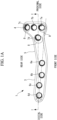
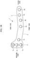
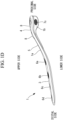
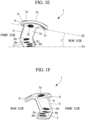
- Figs. 1A to 1F illustrate a bone plate 1
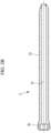
- Figs. 2A and 2B illustrate a bone fixation member 2 to be inserted into any of through-holes 6a to 6d and 7a to 7d of the bone plate 1 for fixing the bone plate 1 to a shin bone A
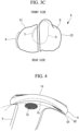
- Figs. 3A and 3B illustrate an example of a usage state of the bone plate 1 and the bone fixation member 2.
- the bone plate system includes a bone plate 1 and a plurality of bone fixation members 2.
- the bone plate system is applied to the side surface of the shin bone A where the side surface of an epiphysis C protrudes relative to the side surface of a diaphysis D.
- the description of this embodiment relates to a case where the bone plate system is used in tibial condylar valgus osteotomy (TCVO) that involves cutting the inner epiphysis C of the shin bone A into an L-shape.
- TCVO tibial condylar valgus osteotomy
- TCVO involves cutting the inner epiphysis C of the shin bone A into an L-shape from an inner side surface to a joint surface B and disconnecting a bone fragment C1 from the inner epiphysis C. Subsequently, the bone fragment C1 is rotated while being lifted upward so as to open a cut area E, and the outer joint surface B is brought into contact with the outer joint surface of the thigh bone. An artificial bone is inserted into the opened cut area E in accordance with the necessity. Then, the bone plate 1 is disposed on the inner side surface of the shin bone A, and the bone plate 1 is fixed to the epiphysis C and the diaphysis D by using the bone fixation members 2.
- the disconnected bone fragment C1 is lifted by being rotated around substantially the center of the joint surface B. Therefore, as compared with HTO, the bone fragment C1 protrudes significantly inward relative to the diaphysis D. Furthermore, since the position of the bone fragment C1 is corrected such that the inner joint surface B conforms to the joint surface of the thigh bone depending on differences in the shape of the joint surface B among individuals, the bone fragment C1 may be lifted toward the front side or toward the rear side. Moreover, a gap may be formed in the joint surface B between the bone fragment C1 and an outer epiphysis C2.
- the bone having undergone the correction in TCVO is in a form significantly different from that of the bone of a normal knee.
- the bone plate 1 includes a long-plate-shaped main section 3, a transverse section 4 disposed at one end of the main section 3, and a plate-shaped coupling section 5 that extends between the main section 3 and the transverse section 4 and that couples the main section 3 and the transverse section 4 to each other.
- the transverse section 4 extends in a direction intersecting the longitudinal direction of the main section 3 and is a plate that is shorter than the main section 3. Therefore, in a front view from the thickness direction of the main section 3, the bone plate 1 is a substantially L-shaped or T-shaped plate member. Furthermore, the bone plate 1 has an upper surface 1a and a lower surface 1b that are opposite to each other in the thickness direction.
- the bone plate 1 has a proximal side, a distal side, a front side, a rear side, an upper side, and a lower side respectively corresponding to the proximal side, the distal side, the front side, the rear side, the inner side, and the outer side of the shin bone A.
- the bone plate 1 in the reference drawings is used for the shin bone A of the left leg.
- the transverse section 4 is disposed at the proximal side of the main section 3, and the upper surface 1a and the lower surface 1b are disposed at the upper side and the lower side, respectively.
- the bone plate 1 is disposed on the inner side surface of the shin bone A such that the lower surface 1b is in contact with the surface of the shin bone A.
- the main section 3 has a width ranging between 11 mm and 18 mm
- the transverse section 4 has a width ranging between 20 mm and 40 mm, or preferably between 25 mm and 35 mm
- the coupling section 5 has a width ranging between 12 mm and 25 mm.
- the thickness of the bone plate 1 is preferably 3 mm ⁇ 1 mm for achieving both high strength and thinness of the bone plate 1.
- a width is the dimension in the transverse direction of the main section 3.
- the main section 3 has the plurality of through-holes 6a to 6d arranged with a distance therebetween and extending through the main section 3 in the thickness direction thereof.
- the transverse section 4 has the plurality of through-holes 7a to 7d arranged with a distance therebetween and penetrating through the transverse section 4 in the thickness direction thereof.
- the coupling section 5 does not have through-holes for the bone fixation members 2 except for the through-holes at the boundary with the main section 3 and at the boundary with the transverse section 4.
- the main section 3 has four through-holes 6a, 6b, 6c, and 6d arranged in the longitudinal direction of the main section 3, and the transverse section 4 has four through-holes 7a, 7b, 7c, and 7d arranged in two rows.
- the number of through-holes in each of the main section 3 and the transverse section 4 may be one, two, three, or five or more. Furthermore, the plurality of through-holes in the transverse section 4 may be arranged in only one row in the longitudinal direction of the transverse section 4.
- the main section 3 is disposed on the inner side surface of the diaphysis D and along the longitudinal direction of the diaphysis D, and is fixed to the diaphysis D by using a plurality of bone fixation members 2.
- the transverse section 4 is disposed on the inner side surface of the bone fragment C1 and along the front-rear direction of the epiphysis C, and is fixed to the epiphysis C by using a plurality of bone fixation members 2.
- the coupling section 5 is disposed at the opened cut area E.
- the area near the boundary between the transverse section 4 and the coupling section 5 is located at a corner of the distal end of the bone fragment C1.
- the boundary between the transverse section 4 and the coupling section 5 may have a upwardly convex shape.
- the bone plate 1 curves in the width direction (i.e., the transverse direction of the main section 3) entirely from the proximal end to the distal end, and the lower surface 1b is recessed in conformity to the protruding surface of the shin bone A.
- the lower surface 1b of the transverse section 4 in order to closely fit the lower surface 1b of the transverse section 4 onto the inner side surface of the bone fragment C1, the lower surface 1b of the transverse section 4 preferably extends between two circular arcs Q1 and Q2 in a side view of the bone plate 1 as viewed along the shorter-dimension-side axis of the transverse section 4 from the proximal side.
- the circular arcs Q1 and Q2 extend through both front and rear ends of the transverse section 4.
- the radius of curvature of the circular arc Q1 is 20 mm
- the radius of curvature of the circular arc Q2 is 40 mm.
- Each bone fixation member 2 is a rod-like member and is, for example, a bone screw or a bone pin. As shown in Fig. 2A , the bone fixation member 2 has a rod-like shaft 2a to be inserted into the shin bone via any of the through-holes 6a to 6d and 7a to 7d and a head 2b that is fixed to the base end of the shaft 2a and that has a diameter larger than that of the shaft 2a.
- the bone fixation member 2 may have a hollow section 2c extending through the bone fixation member 2 along the longitudinal axis of the shaft 2a.
- the outer peripheral surface of the head 2b is provided with a male thread.
- the male thread is fastened to a female thread formed in the inner peripheral surface of any of the through-holes 6a to 6d and 7a to 7d, so that the shaft 2a is disposed coaxially with any of the through-holes 6a to 6d and 7a to 7d.
- the bone fixation member 2 is a bone screw
- at least a part of the outer peripheral surface of the shaft 2a is provided with a male thread.
- the bone fragment C1 In TCVO, the bone fragment C1 is completely disconnected from the diaphysis D and the outer epiphysis C2. Therefore, the bone fragment C1 needs to be securely fixed to the outer epiphysis C2 continuing from the diaphysis D by using the bone fixation members 2. Moreover, a gap may sometimes be formed between the bone fragment C1 and the outer epiphysis C2.
- the bone fixation members 2 used for securing the transverse section 4 each have a long shaft 2a that can reach the outer side surface of the diaphysis D or near the outer surface thereof.
- rod-like members such as wires
- the through-holes 6a to 6d and 7a to 7d may each receive a rod-like member other than a bone fixation member 2.
- some of the through-holes 6a to 6d and some of the through-holes 7a to 7d do not need to have female threads.
- the coupling section 5 is twisted forward around an axis parallel to the longitudinal axis of the main section 3 from the proximal side toward the distal side, and the main section 3 is disposed at the forward-twisted position relative to the transverse section 4.
- the inner side surface of the diaphysis D is offset forward relative to the inner side surface of the bone fragment C1.
- the main section 3 and the transverse section 4 can be properly disposed on the inner side surface of the diaphysis D and the inner side surface of the bone fragment C1, respectively.
- an angle ⁇ formed between a plane P1 and a plane P2 preferably ranges between 8° and 30° in view of the differences in the bone shape of the diaphysis D among individuals.
- the angle ⁇ corresponds to a twist angle between the main section 3 and the transverse section 4.
- the plane P1 is parallel to the shorter-dimension-side axis of the transverse section 4 and is in contact with both the front and rear ends of the lower surface 1b of the main section 3.
- the plane P2 is parallel to the shorter-dimension-side axis of the transverse section 4 and is in contact with both the front and rear ends of the lower surface 1b of the transverse section 4.
- the main section 3 and the transverse section 4 are parallel or substantially parallel to each other, and the coupling section 5 is inclined downward from the proximal side toward the distal side relative to the longitudinal direction of the main section 3.
- the bone plate 1 curves in a cranked shape in which the main section 3 and the transverse section 4 are offset relative to each other in a direction parallel to the thickness direction.
- the transverse section 4 is offset upward relative to the main section 3.
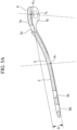
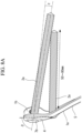
- Fig. 5A is a vertical sectional view of the bone plate 1, taken along the shorter-dimension-side axis of the transverse section 4.
- an offset amount ⁇ between the main section 3 and the transverse section 4 is preferably 9 mm ⁇ 3 mm, and is more preferably 9 mm ⁇ 1 mm.
- the offset amount ⁇ is the distance between two intersection points Pi and Pj in a direction orthogonal to the longitudinal axis of the main section 3.
- intersection point Pi is where the center axis of the most-proximal through-hole 6a in the main section 3 and the lower surface 1b intersect each other
- intersection point Pj is where the center axis of the most-proximal through-hole 7a in the transverse section 4 and the lower surface 1b intersect each other.
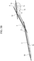
- Figs. 5B and 5C are vertical sectional views of the bone plate 1, taken along the shorter-dimension-side axis of the transverse section 4, and illustrate a design example of the bone plate 1 for achieving an appropriate offset amount ⁇ between the main section 3 and the transverse section 4.
- an angle ⁇ is 155° ⁇ 10°, and an angle ⁇ is 160° ⁇ 10°. More preferably, the angle ⁇ is 160° ⁇ 5°, and the angle ⁇ is 165° ⁇ 5°.
- the angle ⁇ is formed between the shorter-dimension-side axis of the transverse section 4 and the longitudinal axis of the coupling section 5, and the angle ⁇ is formed between the longitudinal axis of the coupling section 5 and the longitudinal axis of the main section 3.
- a length L2 is 38.5 mm ⁇ 5 mm
- the sum of a length L1 and the length L2 is 59 mm ⁇ 5 mm
- the sum of the length L1, the length L2, and a length L3 ranges between 104 mm and 135 mm.
- the length L1 is the length between the proximal end of the transverse section 4 and the center axis of the most-distal through-hole 7d in the transverse section 4.
- the length L2 is the length between the center axis of the most-distal through-hole 7d in the transverse section 4 and the center axis of the most-proximal through-hole 6a in the main section 3.
- the length L3 is the length between the center axis of the most-proximal through-hole 6a in the main section 3 and the distal end of the main section 3.
- the inner epiphysis C is cut into an L-shape, and the cut area E between the bone fragment C1 and the diaphysis D is opened by lifting the bone fragment C1 of the inner epiphysis C while rotating the bone fragment C1 around substantially the center of the joint surface B.
- An artificial bone is inserted into the opened cut area E, where necessary.
- the bone plate 1 is disposed on the inner side surface of the shin bone A such that the bone plate 1 extends astride the opened cut area E.
- the transverse section 4 is fixed to the epiphysis C by inserting the bone fixation members 2 into the epiphysis C via the through-holes 7a to 7d, and the main section 3 is fixed to the diaphysis D by inserting the bone fixation members 2 into the diaphysis D via the through-holes 6a to 6d.
- the inner side surface of the shin bone A has a shape in which the inner side surface of the bone fragment C1 protrudes significantly inward relative to the inner side surface of the diaphysis D.
- the bone plate 1 according to this embodiment has a cranked shape in which the transverse section 4 is offset relative to the main section 3 in the direction corresponding to the direction in which the bone fragment C1 protrudes relative to the diaphysis D. In a state where the cut area E is opened, this shape is in conformity to the inner side surface of the shin bone A. Therefore, the bone plate 1 can be suitably applied to TCVO.
- the bone plate 1 can be disposed on the shin bone A such that the main section 3 and the transverse section 4 come into contact with the inner side surface of the diaphysis D and the inner side surface of the epiphysis C, respectively, thereby preventing lifting of the bone plate 1 from the bone surface.
- the lifting of the bone plate 1 from the surface of the shin bone A may lead to, for example, stretching of the skin at the inner side of the knee.
- This embodiment can prevent an effect on the soft tissue caused by the lifting of the bone plate 1 from the surface of the shin bone A.
- the through-holes 7a to 7d in the transverse section 4 are preferably arranged in at least two rows in the direction of the shorter-dimension-side axis of the transverse section 4.
- the three through-holes 7a to 7c are disposed in the first row at the proximal side, and the single through-hole 7d is disposed in the second row at the distal side.
- the through-hole 7a to 7c in the first row are preferably arranged at regular intervals.
- the bone fragment C1 significantly lifted at the proximal side can be secured more stably by two rows of the bone fixation members 2 in the vertical direction.
- the through-hole 7d in the second row of the transverse section 4 is preferably provided at the boundary between the transverse section 4 and the coupling section 5 or at a position near the boundary, and the through-hole 6a at the most-proximal side of the main section 3 is preferably provided at the boundary between the coupling section 5 and the main section 3 or at a position near the boundary.
- the minimal distance in the lower surface 1b between the bone fixation members 2 extending through the through-holes 7a, 7b, and 7c in the first row and the bone fixation member 2 extending through the through-hole 7d in the second row range between 3 mm and 15 mm.
- a gap between the through-hole 7d in the second row and the through-hole 6a at the most-proximal side of the main section 3 preferably ranges between 28. 5 mm and 45.0 mm.
- the aforementioned gap is the distance between the proximal edge of the through-hole 6a and the distal edge of the through-hole 7d and corresponds to a minimal distance between the under-head of the bone fixation member 2 extending through the through-hole 7d and the under-head of the bone fixation member 2 extending through the through-hole 6a.
- the outer diameter of the shaft 2a preferably ranges between 4.4 mm and 6.5 mm from the standpoint of strength.
- the bone plate 1 be substantially L-shaped such that the transverse section 4 extends rearward relative to the coupling section 5 and the main section 3 in plan view.
- all of the through-holes 7a to 7d in the transverse section 4 are preferably disposed at the rear side of the longitudinal axis of the main section 3 indicated with a double-dot chain line in Fig. 1A .
- the extensions of at least two center axes within the through-holes 6a to 6d in the main section 3 intersect the extensions of the center axes of all of the through-holes 7a to 7d in the transverse section 4 between the front and rear ends of the bone plate 1 in the transverse direction of the main section 3.
- the inner side surface of the epiphysis C is offset rearward relative to the inner side surface of the diaphysis D.
- the main section 3 and the transverse section 4 can be disposed more readily on the inner side surface of the diaphysis D and the inner side surface of the epiphysis C, respectively, as compared with a substantially T-shaped bone plate 1.
- this arrangement facilitates proper insertion of the bone fixation members 2 having the long shafts 2a into the epiphysis C and the diaphysis D.
- the longitudinal axis of the main section 3 and the longitudinal axis of the coupling section 5 may form an angle with each other, and the longitudinal axis of the coupling section 5 and the shorter-dimension-side axis of the transverse section 4 may form an angle with each other.
- the coupling section 5 is inclined forward from the proximal side toward the distal side relative to the shorter-dimension-side axis of the transverse section 4, and the angle between the longitudinal axis of the main section 3 and the longitudinal axis of the coupling section 5 is about 165°.
- the through-hole 7d in the second row is preferably disposed between the two through-holes 7a and 7b at the front side of the first row.
- the soft tissue around the epiphysis C receives a load.
- the through-hole 7d in the second row is provided near the center of the transverse section 4 in the width direction, it is preferable that the through-hole 7d be located between the two through-holes 7a and 7b at the front side in view of the load on the soft tissue.
- Fig. 6 in a side view from the proximal side along the shorter-dimension-side axis of the transverse section 4, it is preferable in this embodiment that the center axes of all the through-holes 7a to 7d in the transverse section 4 be oriented in different directions from one another.
- solid lines indicate the center axes of the through-holes 7a to 7d.
- the center axis of the through-hole (i.e., second through-hole) 7b at the center of the first row is inclined forward from the upper surface 1a toward the lower surface 1b relative to the normal to the tangent plane of the lower surface 1b in the through-hole 7b, and is preferably inclined at 8.5° ⁇ 5° relative to the normal.
- the center axis of the through-hole (i.e., first through-hole) 7a at the front side in the first row is inclined forward from the upper surface 1a toward the lower surface 1b relative to the normal to the tangent plane of the lower surface 1b in the through-hole 7a, and is preferably inclined at 23° ⁇ 5° relative to the normal.
- the center axis of the through-hole (i.e., third through-hole) 7c at the rear side in the first row is inclined rearward from the upper surface 1a toward the lower surface 1b relative to the normal to the tangent plane of the lower surface 1b in the through-hole 7c, and is preferably inclined at 9.5° ⁇ 5° relative to the normal.
- the through-hole 7d in the second row is inclined forward from the upper surface 1a toward the lower surface 1b relative to the normal to the tangent plane of the lower surface 1b in the through-hole 7d, and is preferably inclined at 5° ⁇ 5° relative to the normal.
- each single-dot chain line indicates the normal to the tangent plane of the lower surface 1b in each of the through-holes 7a, 7b, and 7c.
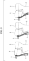
- the bone plate 1 In TCVO, the skin-cutting position tends to be located toward the front side of the knee. Therefore, as shown in the left part of Fig. 7 , the bone plate 1 is often disposed toward the front side of the shin bone A. With the center axes of the through-holes 7a to 7d in the transverse section 4 being entirely inclined forward in the insertion direction of the bone fixation members 2, as mentioned above, the long shafts 2a can be properly inserted into the epiphysis C without protruding from the surface of the epiphysis C even in a case where the bone plate 1 is disposed toward the front side of the shin bone A. Furthermore, as shown in the right part of Fig. 7 , even in a case where the bone plate 1 is disposed toward the rear side of the shin bone A, the long shafts 2a can be inserted into the epiphysis C without protruding from the surface thereof.
- the center axes of the through-holes 7a, 7b, and 7c in the first row be inclined toward one another in the front-rear direction as the center axes extend downward.
- the center axes of the through-holes 7a, 7b, and 7c are inclined at angles where the shaft 2a of the bone fixation member 2 extending through the center through-hole 7b comes into contact with the shafts 2a of the bone fixation members 2 extending through the front and rear through-holes 7a and 7c at a position located away from the lower surface 1b by 80 mm to 120 mm.
- the shafts 2a of the three bone fixation members 2 extending through the through-holes 7a, 7b, and 7c converge within the epiphysis C. Accordingly, as shown in the left and right parts of Fig. 7 , even in a case where the bone plate 1 is disposed toward the front side or the rear side relative to the shin bone A, the long shafts 2a can be inserted to the outer side surface of the epiphysis C or near the outer side surface without protruding from the bone surface.
- each bone fixation member 2 used has the hollow section 2c.
- a bone fixation member 2 having a hollow section 2c can be used in combination with a wire that guides the insertion of the bone fixation member 2 into the shin bone A.
- the wire is inserted into the bone fragment C1 and the outer epiphysis C2 from the inner side toward the outer side while observing an X-ray image of the shin bone A, and the bone fixation member 2 is inserted into the bone fragment C1 and the outer epiphysis C2 along the guide wire. Accordingly, each bone fixation member 2 can be inserted into the epiphysis C in a desired direction.
- the direction of the center axis of at least one of the through-holes 6a to 6d in the main section 3 be different from the directions of all the through-holes 7a to 7d in the transverse section 4.
- the center axis of at least one of the through-holes 6a to 6d is preferably inclined rearward toward the lower side at an inclination angle larger than those of the through-holes 7c and 7d.
- each shaft 2a can be properly inserted in accordance with the diaphysis D offset forward relative to the epiphysis C.
- the center axes of the three through-holes not arranged on the same straight line in the transverse section 4 be inclined toward one another as the center axes extend downward.
- the directions of the center axes of the through-holes 7a to 7d are designed such that the tip end of the shaft 2a of the bone fixation member 2 extending through the through-hole 7d in the second row is in contact with the tip ends of the shafts 2a of the bone fixation members 2 extending through two of the three through-holes 7a, 7b, and 7c in the first row, preferably, the tip ends of the shafts 2a of the bone fixation members 2 extending through the rear and center through-holes 7c and 7b.
- the tip ends of the three shafts 2a are preferably in contact with one another within the outer epiphysis C2.
- the shaft 2a of the bone fixation member 2 extending through the through-hole 7d is preferably in contact with the two remaining shafts 2a at a position located away from the lower surface 1b by 50 mm to 80 mm.
- the three bone fixation members 2 that are in contact with one another at a single point constitute a three-dimensional truss structure. Accordingly, the load bearing characteristics can be improved, as compared with a case where the three bone fixation members 2 receive a load independently of one another. Moreover, if at least the tip ends of the shafts 2a are individually provided with male threads, the male threads engage with one another at the contact position, so that the three-dimensional truss structure becomes more stable.
- the load bearing characteristics of the three-dimensional truss structure are dependent on the outer diameter of each shaft 2a.
- the outer diameter of each shaft 2a preferably ranges between 4.4 mm and 6.5 mm for ensuring the load bearing characteristics of the three-dimensional truss structure.
- the center axes of the three through-holes 7a, 7b, and 7c arranged in a single row in the longitudinal direction of the transverse section 4 be inclined at the same inclination angle toward the proximal side or the distal side, and that the three bone fixation members 2 extending through the three through-holes 7a, 7b, and 7c in the first row be disposed in the same plane.
- the bone fixation members 2 in the first row are inserted into the epiphysis C at different insertion angles relative to the joint surface B. Therefore, there is a possibility that the bone fixation members 2 used may require shafts 2a with different lengths depending on the insertion angles. In the case where the center axes of the through-holes 7a, 7b, and 7c are inclined at the same inclination angle, the bone fixation members 2 used can have shafts 2a with the same length.
- the center axes of the three through-holes 7a, 7b, and 7c be inclined toward the distal side from the upper surface 1a toward the lower surface 1b such that the three bone fixation members 2 in the same plane are disposed toward the distal side of the bone plate 1 than the proximal side.
- the center axes of the three through-holes 7a, 7b, and 7c are inclined at an angle ⁇ of 5° ⁇ 3° toward the distal side relative to the normal to the tangent plane of the upper surface 1a at the center of the transverse section 4.
- the center axes of the three through-holes 7a, 7b, and 7c be inclined at an angle ⁇ of 77° ⁇ 5° relative to a line segment (see a bold dashed line) that connects the proximal end of the transverse section 4 with the boundary between the transverse section 4 and the coupling section 5.
- each bone fixation member 2 inserted in the epiphysis C can be prevented from interfering with the joint surface B regardless of how the bone plate 1 is disposed on the shin bone A.
- the transverse section 4 is disposed at a position offset toward the distal side from the joint surface B. Therefore, it is not preferable for the three bone fixation members 2 in the first row to be inclined excessively toward the distal side, and the three bone fixation members 2 are preferably inserted parallel to the joint surface B as much as possible. Therefore, as mentioned above, the three through-holes 7a, 7b, and 7c preferably have an inclination angle ⁇ of 5° ⁇ 3° and an inclination angle ⁇ of 77° ⁇ 5°.
- a protrusion 8 may be provided around each of the through-holes 7a, 7c, and 7d in this embodiment.
- Each protrusion 8 bulges upward relative to the upper surface 1a that surrounds the protrusion 8 and is an area with a locally increased thickness.
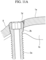
- Figs. 11A and 11B are partial cross-sectional views of the transverse section 4 having a protrusion 8 and the transverse section 4 not having a protrusion, respectively, taken along the center axis of the through-hole 7d in the second row.
- the center axis of the through-hole 7d is inclined toward the distal side from the upper surface 1a toward the lower surface 1b relative to the normal to the tangent plane of the upper surface 1a or the lower surface 1b curved at the position of the through-hole 7d.
- the inclination angle of the center axis of the through-hole 7d relative to the normal is 20° ⁇ 5°.
- the edge of the head 2b protrudes from the upper surface 1a at the obtuse side at which the angle formed between the center axis of the through-hole 7d and the upper surface 1a or the tangent plane is an obtuse angle. Since the head 2b protruding from the upper surface 1a may possibly come into contact with surrounding tissue, it is preferable that the head 2b not protrude from the upper surface 1a, which is smooth. The same applies to the through-holes 7a and 7c.
- a protrusion 8 is provided at the obtuse side of each of the through-holes 7a, 7c, and 7d, but is not provided at the acute side of each of the through-holes 7a, 7c, and 7d.
- the protrusions 8 are provided at the front side of the front through-hole 7a in the first row, the rear side of the rear through-hole 7c in the first row, and the distal side of the through-hole 7d in the second row.
- each protrusion 8 eliminates a step between the upper surface 1a and the top surface of the head 2b in the corresponding through-hole 7a, 7c, or 7d.
- protrusions 8 may be provided around the through-holes 6a to 6d in the upper surface 1a of the main section 3, as well as around the through-hole 7b in the upper surface 1a of the transverse section 4.
- the upper surface 1a may be provided with a countersunk hole that accepts the head 2b. If a countersunk hole is to be provided while ensuring the fastening length between the head 2b and the bone plate 1, the thickness of the bone plate 1 near the corresponding through-hole needs to be increased. Moreover, if the curvature of the bone plate 1 is large or if the center axis of the through-hole is significantly inclined relative to the normal to the upper surface 1a, the countersunk hole needs to be deeper, thus leading to an increase in the thickness of the bone plate 1. In order to reduce the effect that the bone plate 1 has on surrounding tissue, it is preferable that the bone plate 1 be thinner.
- the head 2b can be prevented from protruding from the upper surface 1a without increasing the overall thickness of the transverse section 4, and a thin bone plate 1 can be readily achieved.
- the surface of the protrusion 8 located toward the through-hole 7a, 7c, or 7d may be provided with a female thread, so that the fastening length between the head 2b and the bone plate 1 can be ensured, and the securing force between the bone fixation member 2 and the bone plate 1 can be increased.
- the inclination angle of the center axis of each of the through-holes 7a, 7c, and 7d relative to the corresponding normal ranges between 5° and 25°
- the outer diameter of the each head 2b ranges between 4.5 mm and 8 mm
- the thickness of the area of the bone plate 1 excluding the protrusions 8 is 3 mm ⁇ 1 mm
- the maximum width of each protrusion 8 in a direction intersecting the normal is 12 mm or smaller
- the maximum protruding amount of each protrusion 8 from the upper surface 1a is 1.2 mm or smaller.
- an arbitrary member having a through-hole that accommodates the head of a screw may be provided with the fastening structure having the protrusion 8.
- the through-hole extends through the member from the upper surface to the lower surface thereof and the center axis of the through-hole is inclined relative to the normal to the tangent plane of the upper surface curved at the through-hole, an obtuse region in the region surrounding the through-hole in the upper surface is provided with the protrusion 8.
- the screw is inserted into the through-hole from the upper surface toward the lower surface, and a male thread of the head is fastened to a female thread of the through-hole.
- the bone plate system is used in TCVO in this embodiment, the application of the bone plate system is not limited thereto.
- the bone plate system may be used in an arbitrary treatment of a shin bone in which the side surface of the epiphysis protrudes relative to the side surface of the diaphysis. Therefore, the bone plate 1 may be applied to sites other than the inner side surface of the shin bone A.
Landscapes
- Health & Medical Sciences (AREA)
- Orthopedic Medicine & Surgery (AREA)
- Surgery (AREA)
- Life Sciences & Earth Sciences (AREA)
- Heart & Thoracic Surgery (AREA)
- Nuclear Medicine, Radiotherapy & Molecular Imaging (AREA)
- Engineering & Computer Science (AREA)
- Biomedical Technology (AREA)
- Neurology (AREA)
- Medical Informatics (AREA)
- Molecular Biology (AREA)
- Animal Behavior & Ethology (AREA)
- General Health & Medical Sciences (AREA)
- Public Health (AREA)
- Veterinary Medicine (AREA)
- Surgical Instruments (AREA)
Applications Claiming Priority (1)
| Application Number | Priority Date | Filing Date | Title |
|---|---|---|---|
| PCT/JP2020/023035 WO2021250853A1 (ja) | 2020-06-11 | 2020-06-11 | 骨プレート |
Publications (3)
| Publication Number | Publication Date |
|---|---|
| EP4166104A1 true EP4166104A1 (de) | 2023-04-19 |
| EP4166104A4 EP4166104A4 (de) | 2024-03-06 |
| EP4166104B1 EP4166104B1 (de) | 2025-02-19 |
Family
ID=78847131
Family Applications (1)
| Application Number | Title | Priority Date | Filing Date |
|---|---|---|---|
| EP20939684.5A Active EP4166104B1 (de) | 2020-06-11 | 2020-06-11 | Knochenplatte |
Country Status (6)
| Country | Link |
|---|---|
| US (1) | US12478414B2 (de) |
| EP (1) | EP4166104B1 (de) |
| JP (1) | JP7434549B2 (de) |
| KR (1) | KR102827241B1 (de) |
| CN (1) | CN115701946B (de) |
| WO (1) | WO2021250853A1 (de) |
Families Citing this family (9)
| Publication number | Priority date | Publication date | Assignee | Title |
|---|---|---|---|---|
| CN114129243B (zh) * | 2021-12-31 | 2025-07-11 | 上海市第六人民医院 | 一种胫骨近端联合截骨术专用内固定装置 |
| USD1017037S1 (en) | 2022-01-27 | 2024-03-05 | Paragon 28, Inc. | Bone plate |
| USD1017036S1 (en) * | 2022-01-27 | 2024-03-05 | Paragon 28, Inc. | Bone plate |
| JP7730773B2 (ja) * | 2022-02-18 | 2025-08-28 | 株式会社日本エム・ディ・エム | 骨固定部材 |
| KR102540589B1 (ko) * | 2022-08-16 | 2023-06-07 | 주식회사 티와이메디칼 | 골 접합용 나사 세트 |
| KR102540580B1 (ko) * | 2022-08-16 | 2023-06-07 | 주식회사 티와이메디칼 | 골 접합용 장치 세트 |
| JP7758455B2 (ja) * | 2023-09-27 | 2025-10-22 | 株式会社日本エム・ディ・エム | 骨プレート装置 |
| USD1099319S1 (en) | 2024-06-07 | 2025-10-21 | Stryker European Operations Limited | Bone plate |
| USD1118930S1 (en) | 2024-06-07 | 2026-03-17 | Stryker European Operations Limited | Bone plate |
Family Cites Families (32)
| Publication number | Priority date | Publication date | Assignee | Title |
|---|---|---|---|---|
| FR2472373A1 (fr) | 1979-12-24 | 1981-07-03 | Tornier Sa | Plaques epiphysaires perfectionnees |
| AT387711B (de) | 1986-07-15 | 1989-03-10 | David Thomas | Knochenfixationsplatte |
| US5938664A (en) * | 1998-03-31 | 1999-08-17 | Zimmer, Inc. | Orthopaedic bone plate |
| ES2211583T3 (es) | 1999-09-13 | 2004-07-16 | Synthes Ag Chur | Sistema de placa osea. |
| DE10153467B4 (de) | 2001-10-30 | 2006-05-24 | Königsee Implantate und Instrumente zur Ostheosynthese GmbH | Vorrichtung zur Stabilisierung der Tibia und/oder des Tibiakopfes nach Osteotomie-Eingriffen |
| ITBO20020224A1 (it) | 2002-04-23 | 2003-10-23 | Citieffe Srl | Supporto stabilizzatore per osteotomie di addizione e sottrazione |
| JP4322039B2 (ja) | 2003-04-17 | 2009-08-26 | 瑞穂医科工業株式会社 | 骨プレート |
| US7951176B2 (en) | 2003-05-30 | 2011-05-31 | Synthes Usa, Llc | Bone plate |
| US7137987B2 (en) | 2004-07-02 | 2006-11-21 | Wright Medical Technology, Inc. | Distal radius bone plating system with locking and non-locking screws |
| US20060173458A1 (en) | 2004-10-07 | 2006-08-03 | Micah Forstein | Bone fracture fixation system |
| US8382807B2 (en) | 2005-07-25 | 2013-02-26 | Smith & Nephew, Inc. | Systems and methods for using polyaxial plates |
| US8523921B2 (en) | 2006-02-24 | 2013-09-03 | DePuy Synthes Products, LLC | Tibial plateau leveling osteotomy plate |
| JP3124178U (ja) | 2006-05-29 | 2006-08-10 | 株式会社ホリックス | 中空スクリュー |
| US8317842B2 (en) | 2007-11-30 | 2012-11-27 | Biomet C.V. | Distal tibia plating system |
| US20090177203A1 (en) | 2008-01-04 | 2009-07-09 | Inbone Technologies, Inc. | Devices, systems and methods for re-alignment of bone |
| EP2273943B1 (de) | 2008-03-27 | 2015-03-18 | Newdeal | Arthrodesesystem für das fussgelenk eines menschlichen patienten |
| US20090248084A1 (en) | 2008-03-27 | 2009-10-01 | Beat Hintermann | Systems and methods for performing ankle arthrodesis in a human patient |
| US9072555B2 (en) | 2008-07-21 | 2015-07-07 | Arthrex, Inc. | Carbon fiber reinforced peek bone plate with titanium fixation screws |
| US8257405B2 (en) | 2008-07-31 | 2012-09-04 | Biomet C.V. | Periarticular bone plate with biplanar offset head member |
| JP5419426B2 (ja) | 2008-11-20 | 2014-02-19 | 株式会社ホリックス | 骨接合装置 |
| JP5505767B2 (ja) | 2009-03-23 | 2014-05-28 | オリンパステルモバイオマテリアル株式会社 | 骨プレートおよび骨プレートシステム |
| PL2623057T3 (pl) | 2010-09-28 | 2024-05-06 | Olympus Terumo Biomaterials Corp. | Płytka kostna oraz system płytek kostnych |
| JP5777047B2 (ja) | 2011-02-16 | 2015-09-09 | オリンパステルモバイオマテリアル株式会社 | 骨プレートシステム |
| FR2980967B1 (fr) * | 2011-10-10 | 2013-11-15 | D L P Sarl | Plaque d'osteosynthese pour une technique d'osteotomie tibiale de valgisation par addition interne |
| CN106132324B (zh) * | 2014-03-26 | 2019-03-22 | 奥林巴斯泰尔茂生物材料株式会社 | 接骨板以及接骨板系统 |
| KR101740905B1 (ko) | 2014-04-18 | 2017-05-29 | 백혜선 | 개방형 근위 경골 절골술을 위한 고정 기구 |
| PL231693B1 (pl) * | 2014-09-12 | 2019-03-29 | Chm Spolka Z Ograniczona Odpowiedzialnoscia | Zespół płytki kostnej z wkrętem kostnym do stabilizacji złamań |
| JP1548337S (de) | 2015-03-20 | 2016-04-25 | ||
| US10335210B2 (en) * | 2016-01-21 | 2019-07-02 | Biomet Manufacturing, Llc | Anatomic plates for medial proximal tibia |
| EP3456276B1 (de) * | 2016-05-11 | 2023-12-27 | Olympus Terumo Biomaterials Corp. | Knochenplatte und knochenplattensystem |
| CN109310457B (zh) | 2016-05-31 | 2022-05-06 | 奥林巴斯泰尔茂生物材料株式会社 | 骨板和骨板系统 |
| JP6270933B2 (ja) * | 2016-07-29 | 2018-01-31 | Kisco株式会社 | 大腿骨骨折用の治療器具及び固定プレート |
-
2020
- 2020-06-11 CN CN202080101778.5A patent/CN115701946B/zh active Active
- 2020-06-11 EP EP20939684.5A patent/EP4166104B1/de active Active
- 2020-06-11 KR KR1020227043238A patent/KR102827241B1/ko active Active
- 2020-06-11 WO PCT/JP2020/023035 patent/WO2021250853A1/ja not_active Ceased
- 2020-06-11 JP JP2022530459A patent/JP7434549B2/ja active Active
-
2022
- 2022-12-07 US US18/076,560 patent/US12478414B2/en active Active
Also Published As
| Publication number | Publication date |
|---|---|
| JP7434549B2 (ja) | 2024-02-20 |
| US12478414B2 (en) | 2025-11-25 |
| US20230102016A1 (en) | 2023-03-30 |
| EP4166104B1 (de) | 2025-02-19 |
| JPWO2021250853A1 (de) | 2021-12-16 |
| EP4166104A4 (de) | 2024-03-06 |
| KR102827241B1 (ko) | 2025-06-27 |
| CN115701946A (zh) | 2023-02-14 |
| KR20230008204A (ko) | 2023-01-13 |
| WO2021250853A1 (ja) | 2021-12-16 |
| CN115701946B (zh) | 2025-11-14 |
Similar Documents
| Publication | Publication Date | Title |
|---|---|---|
| EP4166104B1 (de) | Knochenplatte | |
| EP2040631B1 (de) | Kalkaneusplatte | |
| US10932831B2 (en) | Bone plate and bone plate system | |
| US9149313B2 (en) | Orthopedic plate | |
| US7655029B2 (en) | Bone plate | |
| EP3123971B1 (de) | Knochenplatte und knochenplattensystem | |
| US10905480B2 (en) | Bone plate and bone plate system | |
| US12478415B2 (en) | Clavicle segmental plate system | |
| US20230248404A1 (en) | Bone plate and bone fracture treatment kit | |
| CN213665664U (zh) | 一种肱骨近端大结节锁定板 | |
| CN211325504U (zh) | 一种胫骨近端外侧异形块 | |
| JP7154369B1 (ja) | ブレード体およびこれを有する骨接合具、骨接合具セット | |
| EP4643799A1 (de) | Knochenplatte und knochenplattenkit | |
| KR102422928B1 (ko) | 골접합용판 | |
| JP7284805B2 (ja) | 骨固定用プレート | |
| JP2018015574A (ja) | 大腿骨骨折用の治療器具及び固定プレート | |
| JP2026011545A (ja) | 骨プレートシステム | |
| JP2018015432A (ja) | 大腿骨骨折用の治療器具及び固定プレート |
Legal Events
| Date | Code | Title | Description |
|---|---|---|---|
| STAA | Information on the status of an ep patent application or granted ep patent |
Free format text: STATUS: THE INTERNATIONAL PUBLICATION HAS BEEN MADE |
|
| PUAI | Public reference made under article 153(3) epc to a published international application that has entered the european phase |
Free format text: ORIGINAL CODE: 0009012 |
|
| STAA | Information on the status of an ep patent application or granted ep patent |
Free format text: STATUS: REQUEST FOR EXAMINATION WAS MADE |
|
| 17P | Request for examination filed |
Effective date: 20221206 |
|
| AK | Designated contracting states |
Kind code of ref document: A1 Designated state(s): AL AT BE BG CH CY CZ DE DK EE ES FI FR GB GR HR HU IE IS IT LI LT LU LV MC MK MT NL NO PL PT RO RS SE SI SK SM TR |
|
| P01 | Opt-out of the competence of the unified patent court (upc) registered |
Effective date: 20230427 |
|
| DAV | Request for validation of the european patent (deleted) | ||
| DAX | Request for extension of the european patent (deleted) | ||
| A4 | Supplementary search report drawn up and despatched |
Effective date: 20240207 |
|
| RIC1 | Information provided on ipc code assigned before grant |
Ipc: A61B 17/80 20060101AFI20240201BHEP |
|
| GRAP | Despatch of communication of intention to grant a patent |
Free format text: ORIGINAL CODE: EPIDOSNIGR1 |
|
| STAA | Information on the status of an ep patent application or granted ep patent |
Free format text: STATUS: GRANT OF PATENT IS INTENDED |
|
| INTG | Intention to grant announced |
Effective date: 20240910 |
|
| GRAS | Grant fee paid |
Free format text: ORIGINAL CODE: EPIDOSNIGR3 |
|
| GRAA | (expected) grant |
Free format text: ORIGINAL CODE: 0009210 |
|
| STAA | Information on the status of an ep patent application or granted ep patent |
Free format text: STATUS: THE PATENT HAS BEEN GRANTED |
|
| AK | Designated contracting states |
Kind code of ref document: B1 Designated state(s): AL AT BE BG CH CY CZ DE DK EE ES FI FR GB GR HR HU IE IS IT LI LT LU LV MC MK MT NL NO PL PT RO RS SE SI SK SM TR |
|
| REG | Reference to a national code |
Ref country code: GB Ref legal event code: FG4D |
|
| REG | Reference to a national code |
Ref country code: CH Ref legal event code: EP |
|
| REG | Reference to a national code |
Ref country code: DE Ref legal event code: R096 Ref document number: 602020046599 Country of ref document: DE |
|
| REG | Reference to a national code |
Ref country code: IE Ref legal event code: FG4D |
|
| REG | Reference to a national code |
Ref country code: NL Ref legal event code: MP Effective date: 20250219 |
|
| PG25 | Lapsed in a contracting state [announced via postgrant information from national office to epo] |
Ref country code: RS Free format text: LAPSE BECAUSE OF FAILURE TO SUBMIT A TRANSLATION OF THE DESCRIPTION OR TO PAY THE FEE WITHIN THE PRESCRIBED TIME-LIMIT Effective date: 20250519 |
|
| PG25 | Lapsed in a contracting state [announced via postgrant information from national office to epo] |
Ref country code: FI Free format text: LAPSE BECAUSE OF FAILURE TO SUBMIT A TRANSLATION OF THE DESCRIPTION OR TO PAY THE FEE WITHIN THE PRESCRIBED TIME-LIMIT Effective date: 20250219 |
|
| PG25 | Lapsed in a contracting state [announced via postgrant information from national office to epo] |
Ref country code: PL Free format text: LAPSE BECAUSE OF FAILURE TO SUBMIT A TRANSLATION OF THE DESCRIPTION OR TO PAY THE FEE WITHIN THE PRESCRIBED TIME-LIMIT Effective date: 20250219 |
|
| PG25 | Lapsed in a contracting state [announced via postgrant information from national office to epo] |
Ref country code: ES Free format text: LAPSE BECAUSE OF FAILURE TO SUBMIT A TRANSLATION OF THE DESCRIPTION OR TO PAY THE FEE WITHIN THE PRESCRIBED TIME-LIMIT Effective date: 20250219 |
|
| PGFP | Annual fee paid to national office [announced via postgrant information from national office to epo] |
Ref country code: GB Payment date: 20250620 Year of fee payment: 6 |
|
| REG | Reference to a national code |
Ref country code: LT Ref legal event code: MG9D |
|
| PG25 | Lapsed in a contracting state [announced via postgrant information from national office to epo] |
Ref country code: NO Free format text: LAPSE BECAUSE OF FAILURE TO SUBMIT A TRANSLATION OF THE DESCRIPTION OR TO PAY THE FEE WITHIN THE PRESCRIBED TIME-LIMIT Effective date: 20250519 Ref country code: IS Free format text: LAPSE BECAUSE OF FAILURE TO SUBMIT A TRANSLATION OF THE DESCRIPTION OR TO PAY THE FEE WITHIN THE PRESCRIBED TIME-LIMIT Effective date: 20250619 |
|
| PG25 | Lapsed in a contracting state [announced via postgrant information from national office to epo] |
Ref country code: NL Free format text: LAPSE BECAUSE OF FAILURE TO SUBMIT A TRANSLATION OF THE DESCRIPTION OR TO PAY THE FEE WITHIN THE PRESCRIBED TIME-LIMIT Effective date: 20250219 |
|
| PG25 | Lapsed in a contracting state [announced via postgrant information from national office to epo] |
Ref country code: HR Free format text: LAPSE BECAUSE OF FAILURE TO SUBMIT A TRANSLATION OF THE DESCRIPTION OR TO PAY THE FEE WITHIN THE PRESCRIBED TIME-LIMIT Effective date: 20250219 |
|
| PG25 | Lapsed in a contracting state [announced via postgrant information from national office to epo] |
Ref country code: PT Free format text: LAPSE BECAUSE OF FAILURE TO SUBMIT A TRANSLATION OF THE DESCRIPTION OR TO PAY THE FEE WITHIN THE PRESCRIBED TIME-LIMIT Effective date: 20250620 Ref country code: LV Free format text: LAPSE BECAUSE OF FAILURE TO SUBMIT A TRANSLATION OF THE DESCRIPTION OR TO PAY THE FEE WITHIN THE PRESCRIBED TIME-LIMIT Effective date: 20250219 |
|
| PGFP | Annual fee paid to national office [announced via postgrant information from national office to epo] |
Ref country code: FR Payment date: 20250624 Year of fee payment: 6 |
|
| PG25 | Lapsed in a contracting state [announced via postgrant information from national office to epo] |
Ref country code: BG Free format text: LAPSE BECAUSE OF FAILURE TO SUBMIT A TRANSLATION OF THE DESCRIPTION OR TO PAY THE FEE WITHIN THE PRESCRIBED TIME-LIMIT Effective date: 20250219 Ref country code: GR Free format text: LAPSE BECAUSE OF FAILURE TO SUBMIT A TRANSLATION OF THE DESCRIPTION OR TO PAY THE FEE WITHIN THE PRESCRIBED TIME-LIMIT Effective date: 20250520 |
|
| REG | Reference to a national code |
Ref country code: AT Ref legal event code: MK05 Ref document number: 1767569 Country of ref document: AT Kind code of ref document: T Effective date: 20250219 |
|
| PG25 | Lapsed in a contracting state [announced via postgrant information from national office to epo] |
Ref country code: SE Free format text: LAPSE BECAUSE OF FAILURE TO SUBMIT A TRANSLATION OF THE DESCRIPTION OR TO PAY THE FEE WITHIN THE PRESCRIBED TIME-LIMIT Effective date: 20250219 |
|
| PG25 | Lapsed in a contracting state [announced via postgrant information from national office to epo] |
Ref country code: SM Free format text: LAPSE BECAUSE OF FAILURE TO SUBMIT A TRANSLATION OF THE DESCRIPTION OR TO PAY THE FEE WITHIN THE PRESCRIBED TIME-LIMIT Effective date: 20250219 |
|
| PG25 | Lapsed in a contracting state [announced via postgrant information from national office to epo] |
Ref country code: DK Free format text: LAPSE BECAUSE OF FAILURE TO SUBMIT A TRANSLATION OF THE DESCRIPTION OR TO PAY THE FEE WITHIN THE PRESCRIBED TIME-LIMIT Effective date: 20250219 |
|
| PG25 | Lapsed in a contracting state [announced via postgrant information from national office to epo] |
Ref country code: IT Free format text: LAPSE BECAUSE OF FAILURE TO SUBMIT A TRANSLATION OF THE DESCRIPTION OR TO PAY THE FEE WITHIN THE PRESCRIBED TIME-LIMIT Effective date: 20250219 |
|
| PG25 | Lapsed in a contracting state [announced via postgrant information from national office to epo] |
Ref country code: AT Free format text: LAPSE BECAUSE OF FAILURE TO SUBMIT A TRANSLATION OF THE DESCRIPTION OR TO PAY THE FEE WITHIN THE PRESCRIBED TIME-LIMIT Effective date: 20250219 |
|
| PG25 | Lapsed in a contracting state [announced via postgrant information from national office to epo] |
Ref country code: CZ Free format text: LAPSE BECAUSE OF FAILURE TO SUBMIT A TRANSLATION OF THE DESCRIPTION OR TO PAY THE FEE WITHIN THE PRESCRIBED TIME-LIMIT Effective date: 20250219 Ref country code: EE Free format text: LAPSE BECAUSE OF FAILURE TO SUBMIT A TRANSLATION OF THE DESCRIPTION OR TO PAY THE FEE WITHIN THE PRESCRIBED TIME-LIMIT Effective date: 20250219 |
|
| PG25 | Lapsed in a contracting state [announced via postgrant information from national office to epo] |
Ref country code: RO Free format text: LAPSE BECAUSE OF FAILURE TO SUBMIT A TRANSLATION OF THE DESCRIPTION OR TO PAY THE FEE WITHIN THE PRESCRIBED TIME-LIMIT Effective date: 20250219 |
|
| PG25 | Lapsed in a contracting state [announced via postgrant information from national office to epo] |
Ref country code: SK Free format text: LAPSE BECAUSE OF FAILURE TO SUBMIT A TRANSLATION OF THE DESCRIPTION OR TO PAY THE FEE WITHIN THE PRESCRIBED TIME-LIMIT Effective date: 20250219 |
|
| REG | Reference to a national code |
Ref country code: DE Ref legal event code: R097 Ref document number: 602020046599 Country of ref document: DE |
|
| PLBE | No opposition filed within time limit |
Free format text: ORIGINAL CODE: 0009261 |
|
| STAA | Information on the status of an ep patent application or granted ep patent |
Free format text: STATUS: NO OPPOSITION FILED WITHIN TIME LIMIT |
|
| REG | Reference to a national code |
Ref country code: CH Ref legal event code: L10 Free format text: ST27 STATUS EVENT CODE: U-0-0-L10-L00 (AS PROVIDED BY THE NATIONAL OFFICE) Effective date: 20251231 |
|
| REG | Reference to a national code |
Ref country code: DE Ref legal event code: R119 Ref document number: 602020046599 Country of ref document: DE |
|
| REG | Reference to a national code |
Ref country code: CH Ref legal event code: H13 Free format text: ST27 STATUS EVENT CODE: U-0-0-H10-H13 (AS PROVIDED BY THE NATIONAL OFFICE) Effective date: 20260127 |
|
| 26N | No opposition filed |
Effective date: 20251120 |
|
| PG25 | Lapsed in a contracting state [announced via postgrant information from national office to epo] |
Ref country code: MC Free format text: LAPSE BECAUSE OF FAILURE TO SUBMIT A TRANSLATION OF THE DESCRIPTION OR TO PAY THE FEE WITHIN THE PRESCRIBED TIME-LIMIT Effective date: 20250219 |
|
| PG25 | Lapsed in a contracting state [announced via postgrant information from national office to epo] |
Ref country code: LU Free format text: LAPSE BECAUSE OF NON-PAYMENT OF DUE FEES Effective date: 20250611 |
|
| REG | Reference to a national code |
Ref country code: BE Ref legal event code: MM Effective date: 20250630 |
|
| PG25 | Lapsed in a contracting state [announced via postgrant information from national office to epo] |
Ref country code: IE Free format text: LAPSE BECAUSE OF NON-PAYMENT OF DUE FEES Effective date: 20250611 Ref country code: DE Free format text: LAPSE BECAUSE OF NON-PAYMENT OF DUE FEES Effective date: 20260101 |
|
| PG25 | Lapsed in a contracting state [announced via postgrant information from national office to epo] |
Ref country code: BE Free format text: LAPSE BECAUSE OF NON-PAYMENT OF DUE FEES Effective date: 20250630 |
|
| PG25 | Lapsed in a contracting state [announced via postgrant information from national office to epo] |
Ref country code: CH Free format text: LAPSE BECAUSE OF NON-PAYMENT OF DUE FEES Effective date: 20250630 |