EP4163526A1 - Sleeve-like fastening element and centering element - Google Patents
Sleeve-like fastening element and centering element Download PDFInfo
- Publication number
- EP4163526A1 EP4163526A1 EP21201702.4A EP21201702A EP4163526A1 EP 4163526 A1 EP4163526 A1 EP 4163526A1 EP 21201702 A EP21201702 A EP 21201702A EP 4163526 A1 EP4163526 A1 EP 4163526A1
- Authority
- EP
- European Patent Office
- Prior art keywords
- base element
- section
- unit
- fastening element
- locking
- Prior art date
- Legal status (The legal status is an assumption and is not a legal conclusion. Google has not performed a legal analysis and makes no representation as to the accuracy of the status listed.)
- Granted
Links
- 230000002093 peripheral effect Effects 0.000 claims abstract description 14
- 238000010438 heat treatment Methods 0.000 claims abstract description 13
- 239000000463 material Substances 0.000 claims description 30
- 229920003023 plastic Polymers 0.000 claims description 9
- 238000000926 separation method Methods 0.000 claims description 7
- 239000002184 metal Substances 0.000 description 7
- 238000011161 development Methods 0.000 description 6
- 230000018109 developmental process Effects 0.000 description 6
- 230000003068 static effect Effects 0.000 description 6
- 238000004519 manufacturing process Methods 0.000 description 5
- 239000007789 gas Substances 0.000 description 4
- 230000005283 ground state Effects 0.000 description 4
- 230000007704 transition Effects 0.000 description 4
- 238000001746 injection moulding Methods 0.000 description 3
- 230000000630 rising effect Effects 0.000 description 3
- 230000001070 adhesive effect Effects 0.000 description 2
- 239000003570 air Substances 0.000 description 2
- 230000015572 biosynthetic process Effects 0.000 description 2
- 230000008878 coupling Effects 0.000 description 2
- 238000010168 coupling process Methods 0.000 description 2
- 238000005859 coupling reaction Methods 0.000 description 2
- 239000012080 ambient air Substances 0.000 description 1
- 230000008859 change Effects 0.000 description 1
- 238000010276 construction Methods 0.000 description 1
- 238000001816 cooling Methods 0.000 description 1
- 238000005520 cutting process Methods 0.000 description 1
- 230000001419 dependent effect Effects 0.000 description 1
- 230000005489 elastic deformation Effects 0.000 description 1
- 229920002457 flexible plastic Polymers 0.000 description 1
- 230000006872 improvement Effects 0.000 description 1
- 238000002347 injection Methods 0.000 description 1
- 239000007924 injection Substances 0.000 description 1
- 230000003993 interaction Effects 0.000 description 1
- 238000012423 maintenance Methods 0.000 description 1
- 230000036316 preload Effects 0.000 description 1
- 230000008439 repair process Effects 0.000 description 1
- 230000006641 stabilisation Effects 0.000 description 1
- 238000011105 stabilization Methods 0.000 description 1
- 238000003860 storage Methods 0.000 description 1
- 239000013589 supplement Substances 0.000 description 1
Images


Classifications
-
- F—MECHANICAL ENGINEERING; LIGHTING; HEATING; WEAPONS; BLASTING
- F23—COMBUSTION APPARATUS; COMBUSTION PROCESSES
- F23J—REMOVAL OR TREATMENT OF COMBUSTION PRODUCTS OR COMBUSTION RESIDUES; FLUES
- F23J13/00—Fittings for chimneys or flues
-
- F—MECHANICAL ENGINEERING; LIGHTING; HEATING; WEAPONS; BLASTING
- F16—ENGINEERING ELEMENTS AND UNITS; GENERAL MEASURES FOR PRODUCING AND MAINTAINING EFFECTIVE FUNCTIONING OF MACHINES OR INSTALLATIONS; THERMAL INSULATION IN GENERAL
- F16L—PIPES; JOINTS OR FITTINGS FOR PIPES; SUPPORTS FOR PIPES, CABLES OR PROTECTIVE TUBING; MEANS FOR THERMAL INSULATION IN GENERAL
- F16L7/00—Supporting of pipes or cables inside other pipes or sleeves, e.g. for enabling pipes or cables to be inserted or withdrawn from under roads or railways without interruption of traffic
-
- F—MECHANICAL ENGINEERING; LIGHTING; HEATING; WEAPONS; BLASTING
- F23—COMBUSTION APPARATUS; COMBUSTION PROCESSES
- F23J—REMOVAL OR TREATMENT OF COMBUSTION PRODUCTS OR COMBUSTION RESIDUES; FLUES
- F23J2213/00—Chimneys or flues
- F23J2213/10—Linings
- F23J2213/101—Fastening means therefor
-
- F—MECHANICAL ENGINEERING; LIGHTING; HEATING; WEAPONS; BLASTING
- F23—COMBUSTION APPARATUS; COMBUSTION PROCESSES
- F23J—REMOVAL OR TREATMENT OF COMBUSTION PRODUCTS OR COMBUSTION RESIDUES; FLUES
- F23J2900/00—Special arrangements for conducting or purifying combustion fumes; Treatment of fumes or ashes
- F23J2900/13021—Means for supporting the lining of conducting means, e.g. ducts or chimneys
Definitions
- the present invention relates to a sleeve-like fastening element for peripheral clamping on a pipe unit according to claim 1.
- the present invention also relates to a centering element for the central alignment of a pipe unit, in particular an exhaust gas system of a heating system in a shaft, which in particular runs vertically or is vertically offset in some areas, according to claim 13.
- Fastening elements for being arranged circumferentially on a lateral surface of a tube unit, for example an exhaust system of a heating system are generally known from the prior art.
- the fastening element in the configuration as a centering element, enables the pipe units to be arranged centrally, for example in order to discharge exhaust gases from an exhaust system of a heating system.
- the centering elements are used to guide pipe units in residential buildings, which are intended, for example, to divert the exhaust air from a heating system to the environment, at a distance from the shaft existing on the peripheral side to the free end of the shaft.
- almost the entire lateral surface of the tube unit is in contact with the ambient air in order to achieve optimal cooling of the tube unit.
- an annular space is created between the pipe unit and the shaft, for example to supply the heating system with fresh air.
- a fastener that is designed to interact with separate centering means and thus forms a centering element is already known from the applicant EP 2 746 663 A2 known.
- the known fastening element comprises a base element formed from a metal ring with centering means which can be received by the metal ring and aligned radially with respect to the pipe unit by means of the fastening element.
- Over The clamping means can be used to clamp the metal ring around the circumference of the pipe unit, with the clamping means having a clamping screw for stepless adjustment of the metal ring to the diameter of the pipe unit, which can be screwed into a thread using a tool until the metal ring rests in a non-positive manner on the lateral surface of the pipe unit and can therefore be clamped there.
- the non-positive arrangement of the metal ring means that the centering means distributed around the circumference are aligned radially with respect to the pipe unit in such a way that a central positioning of the pipe unit within the shaft is made possible.
- the present invention is therefore based on the object of specifying a collar-like fastening element which overcomes the disadvantages known from the prior art.
- the object of the present invention is to specify a fastening element that can be produced inexpensively and, in addition to continuous adjustment to the diameter of a tube unit, also allows tool-free assembly and disassembly.
- the object for the fastener is achieved by a collar-like fastener according to claim 1. Furthermore, the object for a centering element is solved by claim 13 .
- the present invention relates to a sleeve-like fastening element for peripheral clamping on a pipe unit, in particular an exhaust system of a heating system, having a strip-shaped basic element, which is configured along an axis of extension in a basic state, for peripheral contact with a lateral surface of the pipe unit in a tightened state, the basic element in particular for receiving of centering means designed as separate components, which in the tightened state can be aligned so as to protrude radially from the pipe unit in order to arrange the pipe unit centrally within a shaft.
- the fastening element according to the invention comprises tightening means with a locking unit and locking means, the locking unit being arranged at a first end of the base element and the locking means forming at least two tightening positions formed adjacent to one another on the base element along the axis of extension.
- the clamping means according to the present invention are designed such that the locking unit can be positioned in one of the at least two clamping positions for the peripheral clamping of the base element to the lateral surface of the tubular unit.
- the invention provides that the base element between the locking unit and the locking means comprises a spring section that is elastically deformable along an expansion path for the non-positive clamping of the base element around the tube unit.
- the basic element has the shape of a band, comprises an upper side and an opposite lower side and extends along the axis of extent in the basic state. In the tightened state is the Bottom on the lateral surface of the tube unit, which is why the top is aligned radially outwards.
- the base element is made of a material with such material properties that the base element can flexibly enclose the lateral surface of the tube unit, but is dimensionally stable with respect to a force being applied along the longitudinal extent of the base element.
- the base element is flexible in such a way that the base element can be adapted to the lateral surface of the tube unit, with an elongation of the length of the base element when a force is applied in a longitudinal direction being small.
- the tightening means which include the locking unit and the locking means, enable the base element to be fixed circumferentially to the tube unit in a tightened state.
- the locking unit is arranged at a first end of the base element and is designed in such a way that it can interact with at least two tightening positions that are formed by the locking means between the first end and an opposite second end.
- the spring section thus enables a continuous adjustment of the longitudinal extent of the base element to the circumference of the tubular unit in order to influence the longitudinal extent of the base element in the clamped state through the expansion path in addition to the rough adjustment of the longitudinal extent by selecting the first tightening position or the at least second tightening position.
- the spring section according to the invention allows fine adjustment of the longitudinal extent of the base element and/or fastening element, as a result of which a non-positive fit of the fastening element can be achieved peripherally to the tube unit.
- the spring section in the base element leads to a restoring force that leads to a uniform all-round frictional connection between the fastening element and the tube unit.
- the spring section is only partially formed in the base element, with the base element only having low elastic properties outside of the spring section.
- the fastening element according to the invention enables tool-free assembly and disassembly, since the locking unit only has to be fixed in one of the at least two tightened positions to form the tightened state.
- no tool is required for this, in order to lock a screw, for example.
- the interaction according to the invention between the spring section designed for elastic tensioning and the selection of one of the at least two tightening positions that are adjacent to one another along the longitudinal extent of the base element enables continuous adjustment of the fastening element to the circumference of the existing pipe unit.
- the spring section is formed by an arcuate elevation of the base element, which increases the expansion path in particular by adjusting it to a flatter state trains.
- the base element comprises a curved and/or arched section which forms a type of leaf spring due to the flexural strength of the base element.
- the spring section can be realized in the base element in a structurally simple and reliable manner in order to adapt the longitudinal extent between two adjacent tightening positions by adjusting the arcuate elevation into a flatter state.
- the arcuate elevation can in particular also be referred to as a partial circle section, with a prestress being able to be generated in the base element as a result of the geometry and/or shape and/or design of the elevation.
- the base element preferably has a reduced thickness in the area of the arcuate elevation. Furthermore, it is preferred if the base element comprises a transition area immediately adjacent to the arcuate elevation, which has a thickness that lies between the material thickness of the arcuate elevation and the thickness of the base element.
- this leads to a particularly good preload in the base element, which leads to an improved frictional connection between the fastening element and the tubular unit.
- the base element together with the spring section and the clamping means, is designed monolithically and/or as a plastic injection molded part made of a plastic material, the plastic material being in particular opposite one another in the longitudinal or circumferential direction acting tensile forces has stiff and / or inflexible material properties.
- the monolithic design leads to a particularly simple production, since the base element, and thus also the fastening element, can be produced in particular by a corresponding injection molding tool.
- no further assembly steps are required to produce the fastening element.
- this also leads to a low error rate in production, since no assembly is required to assemble the fastening element.
- the locking unit comprises a recess for inserting a free end of the base element opposite the first end and a locking lug such that when the free end is inserted into the recess, the locking lug can be fixed in one of the at least two tightening positions of the locking means .
- the free end is thus the second end of the band-shaped basic element, which is arranged opposite to the locking unit.
- a recess is understood to be a material recess, in particular a hole and/or an opening, which enables the free end of the basic element to be received, in order to thus form an annular basic element from the band-shaped basic element.
- the recess aligns and/or positions the locking means, which includes the base element between the first end and the free end.
- the locking lug is a component of the locking unit, which can be brought into engagement with the locking means and is thus fixed in one of the tightening positions formed by the locking means can.
- the locking lug is arranged and/or aligned relative to the recess such that the locking means can be mechanically contacted through the locking lug after inserting the free end, in order to fix the locking lug in one of the tightening positions formed by the locking means.
- the tightened state can also be generated by untrained assistants, since incorrect operation can be almost completely ruled out. Furthermore, by simply inserting the free end and then applying a force to the base element, a selection between one of the at least two clamping positions can be implemented without tools. In addition, in addition to the selection of one of the tightening positions, the force applied also applies a force to the spring section.
- the tool-free assembly and disassembly can thus advantageously be additionally simplified by the present embodiment.
- the locking lug includes a contact surface for releasing the tightened positions by applying force, in particular manually.
- the engagement surface thus enables the clamping means to be detachable in order to release the clamped state of the fastening element again, for example during maintenance or repair work, and thus to prevent the fastening element from being destroyed by the service personnel.
- the contact surface is preferably designed in such a way that the locking lug can be released from the tightened position manually, for example by the fingertips of service personnel, in order to then pull the free end out of the recess again.
- a further preferred embodiment includes that the locking means are formed in sections in the base element and/or that the locking means are formed in a first locking means section and/or a second locking means section and/or a third locking means section and/or at least one fourth locking means section, which in particular in Basic element along the axis of extension are formed spaced apart.
- this leads to a universally usable fastener that can be fixed to pipe units with different diameters.
- the same fastening element can also be used in the case of a regional narrowing of the tubular unit.
- the effort involved in production and/or storage and/or transport is additionally reduced.
- the fastening element can initially be adapted to the diameter of the tube unit by selecting one of the locking means sections. Furthermore, by selecting one of the at least two tightening positions, the fastening element can then also be adapted to the diameter of the pipe unit, for example to compensate for an additional casing formed on the lateral surface of the pipe unit. Finally, the expansion path of the spring section according to the invention results in a further adjustment to the diameter, which can be referred to as fine adjustment of the fastening element.
- a preferred embodiment includes that the locking means includes a plurality of essentially sawtooth-shaped latching steps for forming the at least two tightening positions.
- the sawtooth-shaped latching steps can preferably interact with the locking lug in such a way that a large number of pretensioning positions can be formed in the area of the locking means sections, in which case the longitudinal extent of the fastening element is additionally supplemented by the expansion path formed by the spring element in order to always achieve a non-positive, in particular stepless, adjustment of the fastening element to the tubular unit.
- the locking means comprise a multiplicity of essentially sawtooth-shaped latching steps for forming the at least two tightening positions.
- a sawtooth shape of the latching steps means that in a longitudinal sectional view the locking means have a vertically rising section, which is referred to here as a force application surface, since it interacts in particular with the locking lug to realize the tightened state.
- the vertically rising section then transitions into a falling section, in particular one that falls uniformly and/or linearly, these two sections being repeated periodically along the extension axis.
- the jagged course of the latching steps can also have a roof section and a base section, both of which are aligned horizontally in the above longitudinal sectional view and thus parallel to the upper side of the base element.
- the roof section and the bottom section are alternately arranged between the perpendicularly or vertically rising section and the falling section.
- the roof section thus connects the force application surface, which is aligned essentially perpendicularly to the upper side, with the sloping section, which is also referred to here as the incline section.
- the base section connects the slope section to the force application surface along the axis of extent.
- the large number of these sawtooth-shaped sections can be used to realize a large number of latching steps, each of which forms a pretensioned position in which, in particular, the locking lug can be fixed.
- the latching steps are formed in the upper side of the base element and are preferably formed by the base element itself, which is why production, in particular by injection molding, is technically easy to implement, particularly in connection with the already mentioned monolithic design of the base element.
- the base element is designed in such a way that it has at least one slit-shaped material recess arranged centrally with respect to the width extension of the base element.
- the material recess is formed in sections along the axis of extension in the base element, it also being possible for the base element to have a plurality of such material recesses.
- a material recess is arranged adjacent to one of the at least four locking means sections in the base element. Due to the material cut-out, the base element forms two parallel longitudinal webs on the edge.
- the two longitudinal webs at the edge lead to an improvement in the static friction between the fastening element and the pipe unit in the tightened state on an in particular vertical tubular unit, since the longitudinal webs become jammed and/or wedged.
- This advantageously allows additional stabilization of the fastening element in the tightened state without having to use special materials with good static friction.
- this constructive configuration also expands the inventive idea of a fastening element that can be produced cost-effectively and that can be produced in particular as a monolithic component using a single injection molding process.
- the base element tapers with respect to its width extension in order to form a predetermined separation point for adapting the longitudinal extension of the base element in the tightened state.
- the invention preferably provides that such a predetermined separation point is combined with a large number of locking means sections in order to form a universally usable fastening element that can be arranged on the circumference of pipe units of different thicknesses, in which case protruding end sections of the basic element can then be separated.
- the taper makes it visible to service personnel in which area the separation can take place without negatively influencing the fastening element.
- the base element comprises an eyelet for engaging a tool.
- the eyelet advantageously allows the force for tightening the fastening element to be introduced into the base element by the tool. This enables a further simplification of the assembly of the fastening element, since the spring section can also be subjected to a force indirectly along the expansion path via the tool.
- an eyelet is understood to be a material recess and/or a provided coupling section, in particular a coupling element comprised by the base element, which is designed to interact with a tool. It is provided here that the force can be introduced into the tool either manually by an operator or mechanically by a handling device.
- the base element includes a grip section in some areas.
- the handle section is preferably in the area of the free end, in particular in one associated with the free end End portion arranged to apply a force to the base independent of the locking means portion selected for tightening to select an appropriate tightening position and to deform the spring portion along the elongation path.
- this structural design supplements the tool-free assembly of the fastening element, since the static friction when gripping the base element manually can be improved.
- such a constructive design can also be easily combined in connection with the preferred monolithic design of the basic element.
- the base element has an upper side that can be aligned outwards in the tightened state, in particular with respect to the tube unit, an upper side that can be aligned radially outwards and an upper side that lies opposite the upper side and rests on the lateral surface of the tubular unit in the tightened state and thus comprises an inwardly directed underside, wherein the upper side comprises the plurality of sawtooth-shaped latching steps and/or the gripping section has a plurality of gripping grooves formed on the upper side and the underside.
- the underside of the base element rests on the lateral surface of the tube unit. It is thus aligned radially inwards with respect to the tube unit.
- the opposite upper side of the base element is aligned radially outwards in the tightened state.
- the plurality of sawtooth-shaped latching steps is only formed on the upper side, in order to allow the base element to lie evenly around the circumference on the lateral surface of the tubular unit and to achieve a good frictional connection.
- the grip section is formed by the gripping grooves on the upper side and on the underside of the base element, in order to improve the introduction of a force with the hand into the base element through higher static friction.
- a centering element is also provided for centrically aligning a pipe unit, in particular an exhaust gas system of a heating system, in a shaft that preferably runs vertically and is preferably offset vertically in some areas, with the centering element having, in addition to a fastening element according to the invention, additional centering means which are secured by at least one separate Component are formed so as to align the tube unit in the fixed state of the fastener within the manhole by a uniform spacing of the tube unit from the inner walls of the manhole centrally.
- the tube unit can advantageously have a different geometry.
- a design of the pipe unit that tapers and/or widens radially, in particular in some areas, is also included, with the centering element according to the invention being operatively connected to all of the embodiments can.
- the shaft can also have a round base.
- the shaft can also have a curved and/or kinked and/or straight and/or sloping section, in particular in sections aligned at an angle to the vertical axis, in order to form in particular a shaft that is vertically offset in sections.
- the centering means is thus understood to mean at least one separate component, which can consist of one or more components.
- the centering means comprise a carriage element and a ring section.
- the carriage member includes locking means for mechanically locating the carriage member to the fastener.
- the fixing means are formed by a receptacle for inserting the free end, with the carriage element being able to be positioned as desired along the base element.
- the carriage element is preferably mechanically coupled to the ring section, which is aligned such that it protrudes radially with respect to the pipe unit when the fastening element is clamped in place.
- the ring section is preferably made of a plastic material that is flexible with respect to its radial extent. Thus the tubular unit can be aligned between at least two ring sections within the manhole.
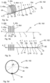
- the Fig. 1a shows the plan view of a collar-like fastener 1 in a basic state 102 according to a first preferred embodiment.
- the fastening element 1 comprises a basic element 2 which is designed in the form of a strip and, in the basic state shown in the figure, extends from a first end 6 along the axis of extension E to an opposite free end 13 .
- the base element 2 comprises a locking unit 5 which, together with locking means 7, forms clamping means 4.
- the locking means 7 are formed in the base element 2 along the axis E of extension.
- the locking means 7 comprise at least two tightening positions 8a, 8b formed adjacent to one another on the base element 2 along the axis of extension E.
- the clamping means 4 are designed in such a way that the locking unit 5 can be fixed in one of the at least two clamping positions 8a, 8b for clamping the base element 2 on the peripheral surface of the tubular unit 100 in order to achieve a clamping state 101 of the fastening element 1.
- the locking means 7 are formed in sections in the base element 2 .
- the locking means 7 include a first locking means section 15a, a second locking means section 15b, a third locking means section 15c and a fourth locking means section 15d, which each form at least two clamping positions 8a, 8b for clamping the locking unit 5 in the clamped state 101.
- the base element 2 comprises a spring section 10 which is elastic along an expansion path which runs in the direction of the extension axis E in the basic state 102 is deformable.
- the spring section 10 acting as an elastic buffer and/or expansion section is arranged directly adjacent to the first end 6 and thus to the locking unit 5 in the base element 2 .
- the spring section 10 leads to an adjustment of the longitudinal extension of the base element 2 in the tightened state 101 in order to realize a fine adjustment of the longitudinal extension of the fastening element 1 in addition to the selection of one of the at least two tightening positions 8a, 8b of the four locking means sections 15a-d.
- this enables the non-positive clamping of the fastening element 1 to the lateral surface of a tube unit 100 in the clamping state, which will be explained in more detail later.
- the top view also shows that the base element 2 comprises a plurality of slot-shaped material recesses 17 which are aligned along the axis of extension E and lead to the formation of two longitudinal webs 26, 27 running parallel to one another in certain areas at the edge.
- the clamping of the fastening element 1 around a vertically running tube unit 100 can advantageously be improved by the edge-side longitudinal webs 26, 27, since an improved adhesive effect can be achieved by wedging the longitudinal webs 26, 27 formed in certain areas.
- the sliding of the fastening element 1 on the pipe unit 100 due to the acting weight can be prevented.
- the base element 2 comprises predetermined separation points 18, which are formed by narrowing the width extension of the base element 2 and thus allow the longitudinal extension of the base element 2 to be adjusted by cutting off the free end 13, in particular in the tightened state 101.
- the base element 2 includes an eyelet 19 which is designed to accommodate a tool. Through the eyelet 19 can indirectly A manual or motor force can thus be introduced into the fastening element 1 via the tool in order to realize the tightened state 101 .
- the base element 2 comprises a grip section 20 which is realized by the formation of grip grooves 23 in certain areas. The grip grooves lead to an improved adhesive effect when gripping manually and are formed in the top side 21 and the bottom side 22 of the base element 2 .
- the side view shown of the basic element 2 shows the spring section 10 according to the invention, which is formed by an arcuate elevation 11 in the present case.
- the arcuate elevation 11 becomes flatter, which on the one hand influences the longitudinal extent of the base element 2 through the expansion path and on the other hand generates a restoring force within the base element 2 which, in the tightened state 101, causes the fastening element 1 to rest in a non-positive manner on the lateral surface of the tubular unit 100 allows.
- the 1c the bottom 22 of the base element 2, which rests in the tightened state 101 on the lateral surface of the pipe unit 100 to be centered. It is clear that the underside 22 only includes the multiplicity of gripping grooves 23 in the gripping section 20 , which are formed in the area of the free end 13 in the base element 2 .
- the Figure 2a shows a side sectional view of the base element 2 in the area of the first end 6.
- the base element 2 in this area comprises the locking unit 5 and the spring section 10, which are arranged directly adjacent to one another in the base element 2 and are shown graphically enlarged here.
- the locking unit 5 includes a recess 12 which is designed to receive the free end 13 of the base element 2 .
- the locking unit 5 comes into active contact with one of the four locking means sections 15a-d, which is why it is no longer possible to pull the free end 13 out of the recess 12. It is only possible to further insert the free end 13 into the recess 12 in order to switch from a first tightening position 8a to at least one second tightening position 8b if this is not prevented by the diameter of the tube unit 100 .
- the locking unit 5 includes a locking lug 14 which protrudes in some areas into the recess 12 and which can be fixed in one of the at least two tightening positions 8a, 8b.
- the locking lug 14 includes a contact surface 31, which allows the locking lug 14 to be released from the tightened position in which it is fixed.
- a force for the elastic deformation of the locking lug 14 must be introduced into the contact surface 31 in such a way that the locking lug 14 is deformed in such a way that it is released from the tightened position 8a, 8b.
- the spring section 10 is shown in the figure, which is formed by a partially formed arched elevation 11 in the base element 2 .
- the arcuate elevation 11 becomes flatter when a force is applied along the longitudinal extent of the base element 2, which is why the overall length of the fastening element 1 in the fixed state can also be influenced by the expansion path.
- the overall length of the fastening element 1 in the tightened state 101 can also be adjusted by the expansion path, whereby the stepped longitudinal extent of the fastening element 1, which results from the different prestressing positions 8a, 8b, can be continuously adjusted to the circumference of the pipe unit 100.
- the longitudinal sectional view also shows that the base element 2 has a reduced thickness of essentially 0.8 mm in the area of the arcuate elevation 11, with the base element 2 having a thickness of essentially 1.3mm outside of the arcuate elevation 11.
- the base element includes a transition area with a reduced material thickness of essentially 0.9 mm immediately adjacent to the arcuate elevation 11, in order to achieve optimal prestressing in the base element.
- the force required for the frictional connection can be generated by the restoring force of arcuate elevation 11, which can be influenced by the rigidity of the selected material and the geometry of arcuate elevation 11 and the transition region.
- the Figure 2b shows the one from the Figure 2a known area in a plan view.
- the locking lug 14 is arranged centrally within the recess 12 with respect to the width extension of the base element 2 and is also formed only in a partial area of the recess 12 with regard to the width extension.
- the plan view shows that the arcuate elevation 11 is formed over the entire width of the base element 2 .
- the first locking means section 15a is shown alone in a side view.
- the first locking means section 15a is formed by a multiplicity of essentially sawtooth-shaped elevations in the upper side 21 of the base element 2, one of the at least two clamping positions 8a-b being formed by each elevation becomes.
- the first locking means section 15a extends over a length of 5 mm to 20 mm, in particular 10 mm to 12 mm.
- the Figure 3b shows a section of the Figure 3a on an enlarged scale.
- the tooth-shaped elevations comprise a flat roof section 28 which is formed parallel to the upper side 21 of the base element 2 .
- the roof section 28 connects the force application surface 29 oriented essentially perpendicularly to the upper side 21 to a slope section 30 , a floor section 32 oriented essentially parallel to the upper side 21 being provided between the slope section 30 and the force application surface 29 .
- the sequence of slope section 30, bottom section 32, force application surface 29 and roof section 28 is repeated cyclically in the area of the first locking means section 15a along the axis of extension E, with a corresponding sequence preferably having a longitudinal extension of about 1 mm to 2 mm.
- the 4 shows the base element 2 in the area of the free end 13 on an enlarged scale in a longitudinal sectional view.
- the illustration shows that the handle section 20 is formed in the upper side 21 and in the lower side 22 of the base element 2 by a multiplicity of gripping grooves 23 formed on both sides.
- the illustration also shows the eyelet 19 formed at the end of the base element 2, by means of which a tool for applying a tensile force can be introduced into the base element 2 in order to thus reversibly deform the spring section 10 along the expansion path and to realize the tightened state 101.
- FIG. 5a is a sleeve-like centering element 50 according to the invention for the central alignment of a pipe unit 100, for example an exhaust gas system of a heating system, in a shaft, in particular a vertical shaft, according to a first preferred embodiment shown in a ground state 102 .
- the centering element 50 comprises a fastening element 1 according to the invention for peripheral clamping to a pipe unit 100, for example an exhaust system of a heating system, and centering means 3, which are formed by at least one separate component.
- the fastening element 1 comprises a strip-shaped basic element 2 which is formed along an axis of extension E in the illustrated basic state 102 .
- the base element 2 comprises clamping means 4 which have a locking unit 5 arranged at a first end 6 of the base element 2 . Furthermore, the base element 2 comprises locking means 7 which are designed to interact with the locking unit 5 in order to arrange the fastening element 1 on the peripheral side of the tube unit 100 .
- the locking means 7 comprise a first locking means section 15a, a second locking means section 15b, a third locking means section 15c and a fourth locking means section 15d, which are formed on the upper side 21 of the base element 2 between the locking unit 5 and a free end 13 of the base element 2 .
- All locking means sections 15a-d have a plurality of tightening positions 8a-b, not shown in detail, in order to fix the base element 2 in a tightened state 101 on pipe units 100 of different thicknesses.
- the base element 2 comprises a spring section 10 which is elastically deformable along an expansion path which runs in the direction of the extension axis E in the basic state 102.
- the one used as a buffer section The acting spring section 10 is arranged directly adjacent to the first end 6 and thus to the locking unit 5 and leads to a continuous compensation of the longitudinal extent of the base element 2 between a first tightening position 8a and a second tightening position 8b, in order to ensure that the fastening element 1 rests in a force-fitting manner around the tubular unit 100 to achieve.
- the fastening element 1 includes the centering means 3 in order to enable the central alignment of the pipe unit 100 within the shaft in the tightened state 101 .
- the centering means 3 are formed by four spring washers 40a-d designed as a separate component.
- the spring rings 40a-d each comprise a carriage element 24 and a ring section 25.
- the ring section 25 consists of a plastic material which is flexible for the alignment of the pipe unit 100 in the clamped state 101 with respect to the radial direction of the ring sections 25 and is therefore operatively connected to shafts of different widths for mechanical alignment and centering of the tubular assembly 100 within the well.
- the four spring rings 40a-d are each mechanically connected to the base element 2 via a separate carriage element 24, but can be moved along the base element 2 during commissioning in order to enable the four spring rings 40a-d to be aligned as evenly as possible within the shaft.
- the base element 2 also includes an upper side 21 which is formed opposite to an underside 22 of the base element 2 .
- the base element 2 extends over a total length L of 40 cm, with the width extension BE of the base element 2 preferably being in a range between 9 and 11 mm, in particular 9.4 mm. Furthermore, the view of the upper side 21 of the base element 2 shows that a slot-shaped material recess 17 is provided in the base element 2 between the four locking means sections 15a-d in the middle of the width extension of the base element 2 .
- the slit-shaped material cutout 17 leads to improved static friction between the base element 2 and the tubular unit 100 in a tightened state 101, which will be explained in more detail later, since the two longitudinal webs 26, 27 formed adjacent to the slit-shaped material cutout 17 along the axis of extension E wedge and thus form a Counteract slipping of the fastener 1 in the longitudinal direction of the pipe unit 100 by the improved static friction.
- the base element 2 includes predetermined separation points 18 which are formed by a narrowing of the width extension 2 of the base element 2 .
- the base element 2 Starting from the free end 13 of the base element 2, the base element 2 also comprises an eyelet 19 in order to bring a tool into engagement with the base element 2.
- the base element 2 also includes a gripping section 20 which is formed by forming gripping grooves 23 in certain areas on the upper side 21 and the underside 22 of the base element 2 .
- the Figure 5d shows the already known centering element 50 in the basic state 102 in a view from the front.
- the spring ring 40a comprises a circular ring section 25 made of a plastic material, which is designed to be flexible with respect to its radial extent.
- the radial extent RE of the ring section 25 is between 80 mm and 120 mm, preferably 90 mm and 110 mm, more preferably essentially 108 mm.
- the ring section 25 is mechanically coupled to the base element 2 via the carriage element 24 in order to align the spring ring 40a relative to the tube unit 100 in the tightened state 101, which will be explained in more detail later.
- the Figure 6a now shows the known sleeve-like centering element 50 in the already mentioned clamping state 101 in a perspective view.
- the fastening element 1 is arranged on the peripheral side of a tube unit 100 in such a way that the centering means 3 are aligned so as to project radially with respect to the tube unit 100.
- the pipe unit 100 can thus be aligned within a shaft, not shown graphically, at a uniform distance from the inner walls of the shaft.
- the shaft can have a different geometry.
- the shaft can also have an oval, rectangular or square base.
- the present invention can also be used in connection with shafts that are oriented at an angle to the vertical as a whole or in certain areas, with an essentially centric and/or at least alignment of the pipe unit 100 at a substantially uniform distance from the inner walls, in particular with respect to opposite inner walls of the shaft.
- the underside 22 of the strip-shaped base element 2 rests in a non-positive manner on the outer surface of the tubular unit 100.
- the locking unit 5 arranged at one end on the base element 2 is brought into operative connection with one of the four locking means sections 15a-d in order to fix the locking unit 5 in one of the at least two tightening positions 8a, 8b.
- the illustration also shows that the centering means 3, which are formed by the four spring washers 40a-d, are preferably distributed uniformly around the circumference of the tube unit 100.
- the carriage element 24, which encloses the base element 2 can be moved along the base element 2.
- a force can be applied to the base element 2 by means of a tool, which can be brought into engagement with the base element 2 via the eyelet 19 formed on the free end 13 of the base element 2, in order to move the locking unit 5 in to set one of the clamping positions 8a, 8b.
- the application of force leads to an elongation of the spring section 10 along the elongation path, in order to realize the non-positive fit of the fastening element 1 around the tube unit 100 and to compensate for the stepped longitudinal extension of the fastening element 1, which is formed by the at least two fixed clamping positions 8a, 8b .
- the non-positive fit of the base element 2 on the tube unit 100 results in the carriage elements 24 being fixed at the previously selected circumferential positions of the tube unit 100 .
- the Figure 6b shows the known centering element 50 in the tightened state 101 in a side view. It can be clearly seen that the first spring ring 40a is arranged opposite the third spring ring 40c. Furthermore, the fourth spring ring 40d protrudes from the plane of the drawing. This representation also shows that the fastening element 1 according to the invention is arranged on a tube unit 100 with a diameter D of 8 cm.
- the tubular assembly 100 can be deployed within a manhole having an internal transverse and/or longitudinal extent of between 10cm to 25cm.
- the strip-shaped base body 2 can also be combined with alternative centering means 3, which is technically easy to implement due to the design as a separate component.
- the Figure 6c shows the known centering element 50 in the tightened state 101 in a plan view.
- FIG. 7a-c the cross-sectional view of different shafts 60a-c is shown, in which a pipe unit 100, not shown graphically, can be arranged centrally by means of a centering element 50 according to the invention.
- the shaft 60b can also have a square base according to the Figure 7b exhibit.
- centering element 50 for centric alignment of a pipe unit 100 in a shaft 60c with a rectangular Floor area according to Figure 7c can interact, wherein the centric alignment then relates to the two opposite inner walls to which the tube unit 100 should be able to be arranged essentially in the middle.
- the Figure 8a 12 shows a longitudinal section of the duct 60a with a circular cross-section, the duct 60a being oriented vertically and having a rectilinear course.
- circular chute 60a has a vertically offset path, with chute 60a including a central portion 62 connecting a lower vertically oriented section 61 to an upper vertically oriented section 63.
- a plurality of pipe units 100 which are adapted to the longitudinal extent of sections 61-63, can be aligned centrally within the lower, middle and upper sections 61-63.
Landscapes
- Engineering & Computer Science (AREA)
- General Engineering & Computer Science (AREA)
- Mechanical Engineering (AREA)
- Clamps And Clips (AREA)
Abstract
Die vorliegende Erfindung betrifft ein manschettenartiges Befestigungselement zum umfangsseitigen Festspannen an einer Rohreinheit insbesondere eines Abgassystems einer Heizungsanlage, umfassend ein in einem Grundzustand entlang einer Erstreckungsachse ausgebildetes bandförmiges Grundelement zum umfangsseitigen Anliegen an eine Mantelfläche der Rohreinheit in einem Festspannzustand, Festspannmittel mit einer Arretiereinheit, die an einem ersten Ende des Grundelements angeordnet ist und Arretiermitteln, die wenigstens zwei auf dem Grundelement entlang der Erstreckungsachse zueinander benachbart ausgebildete Festspannpositionen ausbilden, wobei die Festspannmittel so ausgebildet sind, dass die Arretiereinheit zum umfangsseitigen Festspannen des Grundelements an die Rohreinheit in einer der wenigstens zwei Festspannpositionen festlegbar ist. Erfindungsgemäß umfasst das Grundelement einen Federabschnitt.The present invention relates to a sleeve-like fastening element for peripheral clamping on a pipe unit, in particular an exhaust system of a heating system, comprising a strip-shaped basic element, which is configured along an axis of extension in a basic state, for peripheral contact with a lateral surface of the pipe unit in a clamped state, clamping means with a locking unit which is attached to a first end of the base element and locking means, which form at least two tightening positions formed adjacent to one another on the base element along the axis of extension, wherein the tightening means are formed in such a way that the locking unit for circumferentially tightening the base element to the tubular unit can be fixed in one of the at least two tightening positions . According to the invention, the base element comprises a spring section.
Description
Die vorliegende Erfindung betrifft ein manschettenartiges Befestigungselement zum umfangsseitigen Festspannen an einer Rohreinheit nach Anspruch 1. Ferner betrifft die vorliegende Erfindung ein Zentrierelement zum zentrischen Ausrichten einer Rohreinheit insbesondere eines Abgassystems einer Heizungsanlage in einem, insbesondere vertikal verlaufenden oder bereichsweise vertikal versetzten Schacht nach Anspruch 13.The present invention relates to a sleeve-like fastening element for peripheral clamping on a pipe unit according to
Aus dem Stand der Technik sind Befestigungselemente zum umfangsseitigen Anordnen an einer Mantelfläche einer Rohreinheit beispielsweise eines Abgassystems einer Heizungsanlage allgemein bekannt. Durch das Zusammenwirken mit separaten Zentriermitteln ermöglicht das Befestigungselement in der Ausgestaltung als ein Zentrierelement das zentrische Anordnen der Rohreinheiten, beispielsweise um Abgase eines Abgassystems einer Heizungsanlage abzuleiten. Die Zentrierelemente werden eingesetzt, um in Wohnbauten Rohreinheiten, die beispielsweise die Abluft einer Heizungsanlage an die Umgebung ableiten sollen, mit Abstand zum umfangsseitig bestehenden Schacht bis zum freien Ende des Schachts zu führen. Zum einen steht somit nahezu die gesamte Mantelfläche der Rohreinheit in Kontakt mit der Umgebungsluft, um eine optimale Kühlung der Rohreinheit zu erzielen. Zum anderen entsteht somit zwischen der Rohreinheit und dem Schacht ein ringförmiger Zwischenraum, um beispielsweise die Heizungsanlage mit Frischluft zu versorgen.Fastening elements for being arranged circumferentially on a lateral surface of a tube unit, for example an exhaust system of a heating system, are generally known from the prior art. By interacting with separate centering means, the fastening element, in the configuration as a centering element, enables the pipe units to be arranged centrally, for example in order to discharge exhaust gases from an exhaust system of a heating system. The centering elements are used to guide pipe units in residential buildings, which are intended, for example, to divert the exhaust air from a heating system to the environment, at a distance from the shaft existing on the peripheral side to the free end of the shaft. On the one hand, almost the entire lateral surface of the tube unit is in contact with the ambient air in order to achieve optimal cooling of the tube unit. On the other hand, an annular space is created between the pipe unit and the shaft, for example to supply the heating system with fresh air.
Ein Befestigungselement, das zum Zusammenwirken mit separaten Zentriermitteln eingerichtet ist und somit ein Zentrierelement bildet, ist von dem Anmelder bereits aus der
Durch die nahezu unverwüstliche Ausgestaltung des bekannten Befestigungselements ist das Positionieren der Rohreinheit über die gesamte Lebensdauer der Heizungsanlage möglich. Allerdings führt die robuste Konstruktion des Zentrierelements zu hohen Materialkosten. Ferner ist beim Eindrehen der Spannschraube für das stufenlose Verstellen des Metallrings ein Werkzeug erforderlich, um das kraftschlüssige Anordnen des Befestigungselements bzw. des Zentrierelements an der Mantelfläche der Rohreinheit zu erzielen.Due to the almost indestructible design of the known fastening element, the positioning of the pipe unit is possible over the entire service life of the heating system. However, the robust construction of the centering element leads to high material costs. Furthermore, when screwing in the clamping screw for the stepless adjustment of the metal ring, a tool is required in order to achieve the non-positive arrangement of the fastening element or the centering element on the lateral surface of the tube unit.
Daher liegt der vorliegenden Erfindung die Aufgabe zugrunde, ein manschettenartiges Befestigungselement anzugeben, das die aus dem Stand der Technik bekannten Nachteile überwindet. Insbesondere ist es Aufgabe der vorliegenden Erfindung ein Befestigungselement anzugeben, das sich kostengünstig herstellen lässt und neben einer stufenlosen Anpassung an den Durchmesser einer Rohreinheit insbesondere auch eine werkzeuglose Montage wie Demontage erlaubt. Ferner ist es Aufgabe der vorliegenden Erfindung ein entsprechendes Zentrierelement anzugeben.The present invention is therefore based on the object of specifying a collar-like fastening element which overcomes the disadvantages known from the prior art. In particular, the object of the present invention is to specify a fastening element that can be produced inexpensively and, in addition to continuous adjustment to the diameter of a tube unit, also allows tool-free assembly and disassembly. Furthermore, it is the object of the present invention to specify a corresponding centering element.
Die Aufgabe für das Befestigungselement wird durch ein manschettenartiges Befestigungselement nach Anspruch 1 gelöst. Ferner wird die Aufgabe für ein Zentrierelement durch Anspruch 13 gelöst.The object for the fastener is achieved by a collar-like fastener according to
Vorteilhafte Weiterbildungen der Erfindung sind in den Unteransprüchen beschrieben.Advantageous developments of the invention are described in the dependent claims.
Die vorliegende Erfindung bezieht sich auf ein manschettenartiges Befestigungselement zum umfangsseitigen Festspannen an einer Rohreinheit insbesondere eines Abgassystems einer Heizungsanlage, aufweisend ein in einem Grundzustand entlang einer Erstreckungsachse ausgebildetes bandförmiges Grundelement zum umfangsseitigen Anliegen an einer Mantelfläche der Rohreinheit in einem Festspannzustand, wobei das Grundelement insbesondere zur Aufnahme von als separate Bauteile ausgebildete Zentriermittel ausgebildet ist, die im Festspannzustand radial abragend zur Rohreinheit ausrichtbar sind, um die Rohreinheit innerhalb eines Schachts zentrisch anzuordnen. Ferner umfasst das erfindungsgemäße Befestigungselement Festspannmittel mit einer Arretiereinheit und Arretiermitteln, wobei die Arretiereinheit an einem ersten Ende des Grundelements angeordnet ist und die Arretiermittel wenigstens zwei auf dem Grundelement entlang der Erstreckungsachse zueinander benachbart ausgebildete Festspannpositionen ausbilden. Ferner sind die Festspannmittel gemäß der vorliegenden Erfindung so ausgebildet, dass die Arretiereinheit zum umfangsseitigen Festspannen des Grundelements an die Mantelfläche der Rohreinheit in einer der wenigstens zwei Festspannpositionen positionierbar ist. In diesem Zusammenhang ist erfindungsgemäß vorgesehen, dass das Grundelement zwischen der Arretiereinheit und den Arretiermitteln einen entlang einer Dehnungsstrecke elastisch verformbaren Federabschnitt zum kraftschlüssigen Festspannen des Grundelements um die Rohreinheit umfasst.The present invention relates to a sleeve-like fastening element for peripheral clamping on a pipe unit, in particular an exhaust system of a heating system, having a strip-shaped basic element, which is configured along an axis of extension in a basic state, for peripheral contact with a lateral surface of the pipe unit in a tightened state, the basic element in particular for receiving of centering means designed as separate components, which in the tightened state can be aligned so as to protrude radially from the pipe unit in order to arrange the pipe unit centrally within a shaft. Furthermore, the fastening element according to the invention comprises tightening means with a locking unit and locking means, the locking unit being arranged at a first end of the base element and the locking means forming at least two tightening positions formed adjacent to one another on the base element along the axis of extension. Furthermore, the clamping means according to the present invention are designed such that the locking unit can be positioned in one of the at least two clamping positions for the peripheral clamping of the base element to the lateral surface of the tubular unit. In this context, the invention provides that the base element between the locking unit and the locking means comprises a spring section that is elastically deformable along an expansion path for the non-positive clamping of the base element around the tube unit.
Das Grundelement weist die Form eines Bandes auf, umfasst eine Oberseite und eine gegenüberliegende Unterseite und erstreckt sich im Grundzustand entlang der Erstreckungsachse. Im Festspannzustand liegt die Unterseite auf der Mantelfläche der Rohreinheit auf, weshalb die Oberseite nach radial außen ausgerichtet wird. Das Grundelement ist im Rahmen der vorliegenden Erfindung aus einem Material mit solchen Materialeigenschaften realisiert, dass das Grundelement die Mantelfläche der Rohreinheit flexibel umschließen kann, jedoch in Bezug auf eine Kraftbeaufschlagung entlang der Längserstreckung des Grundelements formstabil ausgebildet ist. Anders ausgedrückt, das Grundelement ist derart biegsam, dass das Grundelement an die Mantelfläche der Rohreinheit anpassbar ist, wobei eine Dehnung der Länge des Grundelements bei einer längsgerichteten Kraftbeaufschlagung gering ausfällt.The basic element has the shape of a band, comprises an upper side and an opposite lower side and extends along the axis of extent in the basic state. In the tightened state is the Bottom on the lateral surface of the tube unit, which is why the top is aligned radially outwards. In the context of the present invention, the base element is made of a material with such material properties that the base element can flexibly enclose the lateral surface of the tube unit, but is dimensionally stable with respect to a force being applied along the longitudinal extent of the base element. In other words, the base element is flexible in such a way that the base element can be adapted to the lateral surface of the tube unit, with an elongation of the length of the base element when a force is applied in a longitudinal direction being small.
Die Festspannmittel, die die Arretiereinheit und die Arretiermittel umfassen, ermöglichen, dass das Grundelement in einem Festspannzustand umfangsseitig zu der Rohreinheit festlegbar ist. Hierfür ist die Arretiereinheit an einem ersten Ende des Grundelements angeordnet und so ausgebildet, dass diese mit wenigstens zwei Festspannpositionen zusammenwirken kann, die von den Arretiermitteln zwischen dem ersten Ende und einem gegenüberliegenden zweiten Ende ausgebildet werden. Beim Festspannen der Arretiereinheit wird eine Kraft in das Grundelement eingebracht, wobei der erfindungsgemäße Federabschnitt entlang der Dehnungsstrecke verformt und/oder gedehnt wird, um somit die Längserstreckung des Grundelements zu verändern.The tightening means, which include the locking unit and the locking means, enable the base element to be fixed circumferentially to the tube unit in a tightened state. For this purpose, the locking unit is arranged at a first end of the base element and is designed in such a way that it can interact with at least two tightening positions that are formed by the locking means between the first end and an opposite second end. When the locking unit is tightened, a force is introduced into the base element, with the spring section according to the invention being deformed and/or stretched along the expansion path in order to change the longitudinal extent of the base element.
Der Federabschnitt ermöglicht somit eine stufenlose Anpassung der Längserstreckung des Grundelements an den Umfang der Rohreinheit, um neben der Grobeinstellung der Längserstreckung durch die Auswahl der ersten Festspannposition oder der wenigstens zweiten Festspannposition zusätzlich die Längserstreckung des Grundelements im Festspannzustand durch die Dehnungstrecke zu beeinflussen. Anders ausgedrückt, durch den erfindungsgemäßen Federabschnitt erfolgt eine Feineinstellung der Längserstreckung des Grund- und/oder Befestigungselements, wodurch ein kraftschlüssiges Anliegen des Befestigungselements umfangsseitig zur Rohreinheit erzielt werden kann. Ferner führt der Federabschnitt im Grundelement zu einer Rückstellkraft, die rundum zu einem gleichmäßigen Kraftschluss zwischen dem Befestigungselement und der Rohreinheit führt.The spring section thus enables a continuous adjustment of the longitudinal extent of the base element to the circumference of the tubular unit in order to influence the longitudinal extent of the base element in the clamped state through the expansion path in addition to the rough adjustment of the longitudinal extent by selecting the first tightening position or the at least second tightening position. In other words, the spring section according to the invention allows fine adjustment of the longitudinal extent of the base element and/or fastening element, as a result of which a non-positive fit of the fastening element can be achieved peripherally to the tube unit. Furthermore, the spring section in the base element leads to a restoring force that leads to a uniform all-round frictional connection between the fastening element and the tube unit.
Anders ausgedrückt entsteht beim elastischen Verformen des Federabschnitts entlang der Dehnungsstrecke eine im Grundelement zwischen der Arretiereinheit und den Arretiermitteln wirkende Kraft, die das kraftschlüssige Festspannen des Befestigungselements umfangsseitig zur Rohreinheit ermöglicht.In other words, when the spring section is elastically deformed along the expansion path, a force acts in the base element between the locking unit and the locking means, which force enables the fastening element to be tightened non-positively on the circumference of the pipe unit.
Der Federabschnitt ist nur bereichsweise im Grundelement ausgebildet, wobei das Grundelement außerhalb des Federabschnitts lediglich geringe elastische Eigenschaften aufweist.The spring section is only partially formed in the base element, with the base element only having low elastic properties outside of the spring section.
Vorteilhaft ermöglicht das erfindungsgemäße Befestigungselement eine werkzeuglose Montage wie Demontage, da zum Ausbilden des Festspannzustands die Arretiereinheit lediglich in eine der wenigstens zwei Festspannpositionen festgelegt werden muss. Vorteilhaft ist hierfür kein Werkzeug erforderlich, um etwa eine Schraube zu arretieren. Ferner ermöglicht das erfindungsgemäße Zusammenwirken zwischen dem zum elastischen Spannen ausgebildeten Federabschnitt und der Auswahl einer der wenigstens zwei Festspannpositionen, die entlang der Längserstreckung des Grundelements zueinander benachbart sind, eine stufenlose Anpassung des Befestigungselements an den Umfang der bestehenden Rohreinheit.Advantageously, the fastening element according to the invention enables tool-free assembly and disassembly, since the locking unit only has to be fixed in one of the at least two tightened positions to form the tightened state. Advantageously, no tool is required for this, in order to lock a screw, for example. Furthermore, the interaction according to the invention between the spring section designed for elastic tensioning and the selection of one of the at least two tightening positions that are adjacent to one another along the longitudinal extent of the base element enables continuous adjustment of the fastening element to the circumference of the existing pipe unit.
In einer bevorzugten Ausführungsform ist der Federabschnitt durch eine bogenförmige Erhebung des Grundelements ausgebildet, die insbesondere durch das Verstellen in einen flacheren Zustand die Dehnungsstrecke ausbildet. Anders ausgedrückt umfasst das Grundelement einen gekrümmten und/oder gewölbten Abschnitt, der Aufgrund der Biegefestigkeit des Grundelements eine Art Blattfeder ausbildet. Durch Kraftbeaufschlagung, also das Festspannen des Befestigungselements in den Festspannzustand, wird die bogenförmige Erhebung flacher, wodurch die Längserstreckung des Grundelements und/oder des Befestigungselements durch die Dehnungsstrecke vergrößert wird und gleichzeitig im Befestigungselement eine Rückstellkraft entsteht, die das kraftschlüssige Anliegen des Befestigungselements an der Mantelfläche der Rohreinheit ermöglicht. Vorteilhaft kann somit konstruktiv einfach und zuverlässig der Federabschnitt im Grundelement realisiert werden, um die Längserstreckung zwischen zwei benachbarten Festspannpositionen durch das Verstellen der bogenförmigen Erhebung in einen flacheren Zustand anzupassen. In einer Längsschnittansicht kann die bogenförmige Erhebung insbesondere auch als ein Teilkreisabschnitt bezeichnet werden, wobei durch die Geometrie und/oder Form und/oder Ausgestaltung der Erhebung eine Vorspannung im Grundelement erzeugbar ist.In a preferred embodiment, the spring section is formed by an arcuate elevation of the base element, which increases the expansion path in particular by adjusting it to a flatter state trains. In other words, the base element comprises a curved and/or arched section which forms a type of leaf spring due to the flexural strength of the base element. By applying force, i.e. tightening the fastening element in the tightened state, the arcuate elevation becomes flatter, whereby the longitudinal extent of the base element and/or the fastening element is increased by the expansion path and at the same time a restoring force arises in the fastening element, which causes the fastening element to rest against the lateral surface in a non-positive manner the pipe unit allows. Advantageously, the spring section can be realized in the base element in a structurally simple and reliable manner in order to adapt the longitudinal extent between two adjacent tightening positions by adjusting the arcuate elevation into a flatter state. In a longitudinal sectional view, the arcuate elevation can in particular also be referred to as a partial circle section, with a prestress being able to be generated in the base element as a result of the geometry and/or shape and/or design of the elevation.
Das Grundelement umfasst im Bereich der bogenförmigen Erhebung bevorzugt eine reduzierte Dicke. Ferner ist es bevorzugt, wenn das Grundelement unmittelbar benachbart zur bogenförmigen Erhebung ein Übergangsbereich umfasst, der eine Dicke aufweist, die zwischen der Materialdicke der bogenförmigen Erhebung und der Dicke des Grundelements liegt. Vorteilhaft führt dies zu einer besonders guten Vorspannung im Grundelement, die zu einem verbesserten Kraftschluss zwischen Befestigungselement und Rohreinheit führt.The base element preferably has a reduced thickness in the area of the arcuate elevation. Furthermore, it is preferred if the base element comprises a transition area immediately adjacent to the arcuate elevation, which has a thickness that lies between the material thickness of the arcuate elevation and the thickness of the base element. Advantageously, this leads to a particularly good preload in the base element, which leads to an improved frictional connection between the fastening element and the tubular unit.
Weiterbildend ist es vorgesehen, dass das Grundelement zusammen mit dem Federabschnitt und den Festspannmitteln monolithisch und/oder als Kunststoffspritzgussteil aus einem Kunststoffmaterial ausgebildet ist, wobei das Kunststoffmaterial insbesondere gegenüber in Längs- oder Umfangsrichtung wirkende Zugkräfte steife und/oder unflexible Materialeigenschaften aufweist.In a further development, it is provided that the base element, together with the spring section and the clamping means, is designed monolithically and/or as a plastic injection molded part made of a plastic material, the plastic material being in particular opposite one another in the longitudinal or circumferential direction acting tensile forces has stiff and / or inflexible material properties.
Die monolithische Ausgestaltung führt zu einer besonders einfachen Herstellung, da das Grundelement, und somit auch das Befestigungselement, insbesondere durch ein entsprechendes Spritzgusswerkzeug herstellbar ist. Vorteilhaft sind somit keine weiteren Montageschritte zum Erzeugen des Befestigungselements erforderlich. Neben geringen Herstellungskosten führt dies auch zu einer geringen Fehlerrate bei der Produktion, da keine Montage zum Zusammenbau des Befestigungselements erforderlich ist.The monolithic design leads to a particularly simple production, since the base element, and thus also the fastening element, can be produced in particular by a corresponding injection molding tool. Advantageously, no further assembly steps are required to produce the fastening element. In addition to low production costs, this also leads to a low error rate in production, since no assembly is required to assemble the fastening element.
Eine bevorzugte Ausführungsform sieht vor, dass die Arretiereinheit eine Ausnehmung zum Einführen eines dem ersten Ende gegenüberliegenden freien Endes des Grundelements sowie eine Arretiernase umfasst, derart, dass beim Einführen des freien Endes in die Ausnehmung die Arretiernase in einer der wenigstens zwei Festspannpositionen der Arretiermittel festlegbar ist.A preferred embodiment provides that the locking unit comprises a recess for inserting a free end of the base element opposite the first end and a locking lug such that when the free end is inserted into the recess, the locking lug can be fixed in one of the at least two tightening positions of the locking means .
Das freie Ende ist somit das zweite Ende des bandförmigen Grundelements, das gegenüberliegend zu der Arretiereinheit angeordnet ist.The free end is thus the second end of the band-shaped basic element, which is arranged opposite to the locking unit.
Unter Ausnehmung wird vorliegend eine Materialaussparung, insbesondere ein Loch und/oder eine Öffnung, verstanden, die die Aufnahme des freien Endes des Grundelements ermöglicht, um somit aus dem bandförmigen Grundelement ein ringförmiges Grundelement auszubilden. Durch die Ausnehmung erfolgt eine Ausrichtung und/oder Positionierung der Arretiermittel, die das Grundelement zwischen dem ersten Ende und dem freien Ende umfasst. Die Arretiernase ist ein Bestandteil der Arretiereinheit, die in Eingriff mit den Arretiermitteln bringbar ist, und somit in einer der von den Arretiermitteln ausgebildeten Festspannpositionen festgelegt werden kann. Hierbei ist die Arretiernase so relativ zur Ausnehmung angeordnet und/oder ausgerichtet, dass die Arretiermittel nach dem Einführen des freien Endes durch die Arretiernase mechanisch kontaktierbar sind, um somit die Arretiernase in einer der Festspannpositionen, die von den Arretiermitteln ausgebildet werden, festzulegen.In the present case, a recess is understood to be a material recess, in particular a hole and/or an opening, which enables the free end of the basic element to be received, in order to thus form an annular basic element from the band-shaped basic element. The recess aligns and/or positions the locking means, which includes the base element between the first end and the free end. The locking lug is a component of the locking unit, which can be brought into engagement with the locking means and is thus fixed in one of the tightening positions formed by the locking means can. The locking lug is arranged and/or aligned relative to the recess such that the locking means can be mechanically contacted through the locking lug after inserting the free end, in order to fix the locking lug in one of the tightening positions formed by the locking means.
Durch die Schlichtheit der mit der Arretiernase zusammenwirkenden Ausnehmung kann der Festspannzustand auch von ungeschulten Hilfspersonal erzeugt werden, da eine Fehlbedienung nahezu ausgeschlossen werden kann. Ferner lässt sich durch das bloße Einführen des freien Endes und das anschließende Einbringen einer Kraft in das Grundelement werkzeuglos eine Auswahl zwischen einer der wenigstens zwei Festspannpositionen realisieren. Zusätzlich wird neben der Auswahl einer der Festspannpositionen durch die eingebrachte Kraft auch der Federabschnitt kraftbeaufschlagt. Vorteilhaft kann somit durch die vorliegende Ausgestaltung die werkzeuglose Montage wie Demontage zusätzlich vereinfacht werden.Due to the simplicity of the recess interacting with the locking lug, the tightened state can also be generated by untrained assistants, since incorrect operation can be almost completely ruled out. Furthermore, by simply inserting the free end and then applying a force to the base element, a selection between one of the at least two clamping positions can be implemented without tools. In addition, in addition to the selection of one of the tightening positions, the force applied also applies a force to the spring section. The tool-free assembly and disassembly can thus advantageously be additionally simplified by the present embodiment.
Weiterbildend ist es in diesem Zusammenhang zudem vorgesehen, dass die Arretiernase eine Angriffsfläche zum Lösen der Festspannpositionen durch einen, insbesondere manuellen, Krafteintrag umfasst. Die Angriffsfläche ermöglicht somit die Festspannmittel lösbar auszugestalten, um beispielsweise bei Wartungs- oder Reparaturarbeiten den Festspannzustand des Befestigungselements wieder zu lösen und somit eine Zerstörung des Befestigungselements durch das Servicepersonal zu vermeiden. Bevorzugt ist die Angriffsfläche so ausgebildet, dass manuell, beispielsweise durch die Fingerkuppe der Hand von Servicepersonal, die Arretiernase aus der Festspannposition gelöst werden kann, um dann das freie Ende wieder aus der Ausnehmung herauszuziehen.In a further development, it is also provided in this context that the locking lug includes a contact surface for releasing the tightened positions by applying force, in particular manually. The engagement surface thus enables the clamping means to be detachable in order to release the clamped state of the fastening element again, for example during maintenance or repair work, and thus to prevent the fastening element from being destroyed by the service personnel. The contact surface is preferably designed in such a way that the locking lug can be released from the tightened position manually, for example by the fingertips of service personnel, in order to then pull the free end out of the recess again.
Ferner umfasst eine weiter bevorzugte Ausgestaltung, dass die Arretiermittel im Grundelement abschnittsweise ausgebildet sind und/oder dass die Arretiermittel in einem ersten Arretiermittelabschnitt und/oder einem zweiten Arretiermittelabschnitt und/oder einem dritten Arretiermittelabschnitt und/oder wenigstens einem vierten Arretiermittelabschnitt ausgebildet sind, die insbesondere im Grundelement entlang der Erstreckungsachse zueinander beabstandet ausgebildet sind. Vorteilhaft führt dies zu einem universell einsetzbaren Befestigungselement, das an Rohreinheiten mit unterschiedlichen Durchmessern festgelegt werden kann. Vorteilhaft kann somit auch bei einer bereichsweisen Verjüngung der Rohreinheit auf das gleiche Befestigungselement zurückgegriffen werden. Ferner wird zusätzlich der Aufwand bei der Produktion und/oder Lagerung und/oder Transport reduziert.Furthermore, a further preferred embodiment includes that the locking means are formed in sections in the base element and/or that the locking means are formed in a first locking means section and/or a second locking means section and/or a third locking means section and/or at least one fourth locking means section, which in particular in Basic element along the axis of extension are formed spaced apart. Advantageously, this leads to a universally usable fastener that can be fixed to pipe units with different diameters. Advantageously, the same fastening element can also be used in the case of a regional narrowing of the tubular unit. Furthermore, the effort involved in production and/or storage and/or transport is additionally reduced.
Das Befestigungselement ist bei einer solchen Weiterbildung zunächst durch die Auswahl eines der Arretiermittelabschnitte an den Durchmesser der Rohreinheit anpassbar. Weiterhin kann durch die Wahl einer der wenigstens zwei Festspannpositionen dann zusätzlich das Befestigungselement an den Durchmesser der Rohreinheit angepasst werden, um beispielsweise eine auf der Mantelfläche der Rohreinheit zusätzlich ausgebildete Ummantelung auszugleichen. Schließlich erfolgt dann durch die Dehnungsstrecke des erfindungsgemäßen Federabschnitts eine weitere Anpassung an die Durchmesser, die als Feinjustierung des Befestigungselements bezeichnet werden kann.In such a development, the fastening element can initially be adapted to the diameter of the tube unit by selecting one of the locking means sections. Furthermore, by selecting one of the at least two tightening positions, the fastening element can then also be adapted to the diameter of the pipe unit, for example to compensate for an additional casing formed on the lateral surface of the pipe unit. Finally, the expansion path of the spring section according to the invention results in a further adjustment to the diameter, which can be referred to as fine adjustment of the fastening element.
Zudem umfasst eine bevorzugte Ausgestaltung, dass die Arretiermittel eine Vielzahl von im Wesentlichen sägezahnförmigen Raststufen zum Ausbilden der wenigstens zwei Festspannpositionen umfasst. Vorteilhaft können die sägezahnförmigen Raststufen bevorzugt mit der Arretiernase so zusammenwirken, dass im Bereich der Arretiermittelabschnitte eine Vielzahl an Vorspannpositionen ausbildbar sind, wobei dann die Längserstreckung des Befestigungselements zusätzlich durch die vom Federelement ausgebildete Dehnungsstrecke ergänzt wird, um stets eine kraftschlüssige, insbesondere stufenlose Anpassung des Befestigungselements an die Rohreinheit zu erzielen.In addition, a preferred embodiment includes that the locking means includes a plurality of essentially sawtooth-shaped latching steps for forming the at least two tightening positions. Advantageously, the sawtooth-shaped latching steps can preferably interact with the locking lug in such a way that a large number of pretensioning positions can be formed in the area of the locking means sections, in which case the longitudinal extent of the fastening element is additionally supplemented by the expansion path formed by the spring element in order to always achieve a non-positive, in particular stepless, adjustment of the fastening element to the tubular unit.
In einer bevorzugten Ausführungsform umfassen die Arretiermittel eine Vielzahl von im Wesentlichen sägezahnförmigen Raststufen zum Ausbilden der wenigstens zwei Festspannpositionen. Unter einem sägezahnförmigen Verlauf der Raststufen wird verstanden, dass in einer Längsschnittansicht die Arretiermittel einen senkrecht ansteigenden Abschnitt aufweisen, der vorliegend als Krafteintragsfläche bezeichnet wird, da dieser insbesondere mit der Arretiernase zum Realisieren des Festspannzustands zusammenwirkt. Der senkrecht ansteigende Abschnitt geht dann in einen abfallenden, insbesondere gleichmäßig und/oder linear abfallenden Abschnitt über, wobei sich diese beiden Abschnitte entlang der Ersteckungsachse periodisch wiederholen.In a preferred embodiment, the locking means comprise a multiplicity of essentially sawtooth-shaped latching steps for forming the at least two tightening positions. A sawtooth shape of the latching steps means that in a longitudinal sectional view the locking means have a vertically rising section, which is referred to here as a force application surface, since it interacts in particular with the locking lug to realize the tightened state. The vertically rising section then transitions into a falling section, in particular one that falls uniformly and/or linearly, these two sections being repeated periodically along the extension axis.
Weiterbildend kann der zackenförmige Verlauf der Raststufen, der sich mehrfach entlang der Erstreckungsachse wiederholt, auch zusätzlich einen Dachabschnitt und einen Bodenabschnitt aufweisen, die beide in der o.g. Längsschnittansicht horizontal und somit parallel zur Oberseite des Grundelements ausgerichtet sind. Der Dachabschnitt und der Bodenabschnitt sind abwechselnd zwischen dem senkrecht oder vertikal ansteigenden Abschnitt und dem abfallenden Abschnitt angeordnet. Entlang der Erstreckungsachse verbindet der Dachabschnitt somit die im Wesentlichen senkrecht zur Oberseite ausgerichtete Krafteintragsfläche mit dem abfallenden Abschnitt, der vorliegend auch als Steigungsabschnitt bezeichnet wird. Ferner verbindet der Bodenabschnitt entlang der Erstreckungsachse den Steigungsabschnitt mit der Krafteintragsfläche.In a further development, the jagged course of the latching steps, which is repeated several times along the axis of extension, can also have a roof section and a base section, both of which are aligned horizontally in the above longitudinal sectional view and thus parallel to the upper side of the base element. The roof section and the bottom section are alternately arranged between the perpendicularly or vertically rising section and the falling section. Along the axis of extent, the roof section thus connects the force application surface, which is aligned essentially perpendicularly to the upper side, with the sloping section, which is also referred to here as the incline section. Furthermore, the base section connects the slope section to the force application surface along the axis of extent.
Vorteilhaft kann durch die Vielzahl dieser sägezahnförmigen Abschnitte eine Vielzahl von Raststufen realisiert werden, die jeweils eine Vorspannposition ausbilden, in der insbesondere die Arretiernase festlegbar ist. Die Raststufen sind in diesem Zusammenhang in der Oberseite des Grundelements ausgebildet und werden bevorzugt vom Grundelement selbst gebildet, weshalb eine Fertigung insbesondere durch ein Spritzgussverfahren, insbesondere im Zusammenhang mit der bereits erwähnten monolithischen Ausgestaltung des Grundelements, technisch einfach umsetzbar ist.Advantageously, the large number of these sawtooth-shaped sections can be used to realize a large number of latching steps, each of which forms a pretensioned position in which, in particular, the locking lug can be fixed. In this context, the latching steps are formed in the upper side of the base element and are preferably formed by the base element itself, which is why production, in particular by injection molding, is technically easy to implement, particularly in connection with the already mentioned monolithic design of the base element.
In einer bevorzugten Ausführungsform ist das Grundelement derart ausgestaltet, dass es wenigstens eine bezüglich der Breitenerstreckung des Grundelements mittig angeordnete schlitzförmige Materialaussparung aufweist. Die Materialaussparung ist im Grundzustand abschnittsweise entlang der Erstreckungsachse im Grundelement ausgebildet, wobei das Grundelement auch mehrerer solcher Materialaussparungen aufweisen kann. Weiter bevorzugt ist es in diesem Zusammenhang, wenn eine Materialaussparung benachbart zu einem der wenigstens vier Arretiermittelabschnitte im Grundelement angeordnet ist. Durch die Materialaussparung bildet das Grundelement randseitig zwei parallele Längsstege aus. Vorteilhaft führen die beiden randseitigen Längsstege im Festspannzustand an einer insbesondere vertikal verlaufenden Rohreinheit zu einer Verbesserung der Haftreibung zwischen Befestigungselement und Rohreinheit, da es zu einem festklemmen und/oder verkeilen der Längsstege kommt. Hierdurch ist vorteilhaft eine zusätzliche Stabilisierung des Befestigungselements in dem Festspannzustandmöglich, ohne dass spezielle Materialien mit guter Haftreibung eingesetzt werden müssen. Somit erweitert auch diese konstruktive Ausgestaltung die erfinderische Idee eines kostengünstig herstellbaren Befestigungselements, das insbesondere als monolithisches Bauteil durch ein einziges Spritzgussverfahren herstellbar ist.In a preferred embodiment, the base element is designed in such a way that it has at least one slit-shaped material recess arranged centrally with respect to the width extension of the base element. In the basic state, the material recess is formed in sections along the axis of extension in the base element, it also being possible for the base element to have a plurality of such material recesses. In this context, it is further preferred if a material recess is arranged adjacent to one of the at least four locking means sections in the base element. Due to the material cut-out, the base element forms two parallel longitudinal webs on the edge. Advantageously, the two longitudinal webs at the edge lead to an improvement in the static friction between the fastening element and the pipe unit in the tightened state on an in particular vertical tubular unit, since the longitudinal webs become jammed and/or wedged. This advantageously allows additional stabilization of the fastening element in the tightened state without having to use special materials with good static friction. Thus, this constructive configuration also expands the inventive idea of a fastening element that can be produced cost-effectively and that can be produced in particular as a monolithic component using a single injection molding process.
In einer bevorzugten Ausführungsform weist das Grundelement bezüglich seiner Breitenerstreckung eine Verjüngung auf, um eine Solltrennstelle zum Anpassen der Längserstreckung des Grundelements im Festspannzustand auszubilden. Vorteilhaft sieht die Erfindung bevorzugt vor, dass eine derartige Solltrennstelle mit einer Vielzahl von Arretiermittelabschnitten kombiniert wird, um ein universell einsetzbares Befestigungselement auszubilden, das umfangsseitig zu unterschiedlich dicken Rohreinheiten angeordnet werden kann, wobei dann überstehende Endabschnitte des Grundelements abtrennbar sind. Vorteilhaft wird durch die Verjüngung für Servicepersonal sichtbar, in welchem Bereich das Abtrennen erfolgen kann, ohne das Befestigungselement negativ zu beeinflussen.In a preferred embodiment, the base element tapers with respect to its width extension in order to form a predetermined separation point for adapting the longitudinal extension of the base element in the tightened state. Advantageously, the invention preferably provides that such a predetermined separation point is combined with a large number of locking means sections in order to form a universally usable fastening element that can be arranged on the circumference of pipe units of different thicknesses, in which case protruding end sections of the basic element can then be separated. Advantageously, the taper makes it visible to service personnel in which area the separation can take place without negatively influencing the fastening element.
In einer weiteren bevorzugten Ausführungsform umfasst das Grundelement eine Öse zum Eingriff eines Werkzeugs. Vorteilhaft ermöglicht die Öse, dass die Kraft zum Festspannen des Befestigungselements durch das Werkzeug in das Grundelement eingebracht werden kann. Dies ermöglicht eine weitere Vereinfachung der Montage des Befestigungselements, da auch der Federabschnitt entlang der Dehnungsstrecke mittelbar über das Werkzeug kraftbeaufschlagbar ist.In a further preferred embodiment, the base element comprises an eyelet for engaging a tool. The eyelet advantageously allows the force for tightening the fastening element to be introduced into the base element by the tool. This enables a further simplification of the assembly of the fastening element, since the spring section can also be subjected to a force indirectly along the expansion path via the tool.
Unter einer Öse werden im Rahmen der vorliegenden Erfindung eine Materialaussparung und/oder ein bereitgestellter Koppelabschnitt, insbesondere ein vom Grundelement umfasstes Koppelelement verstanden, das zum Zusammenwirken mit einem Werkzeug ausgebildet ist. Hierbei ist es vorgesehen, dass die Kraft in das Werkzeug entweder manuell durch eine Bedienperson oder maschinell durch eine Handhabungsvorrichtung einbringbar ist.Within the scope of the present invention, an eyelet is understood to be a material recess and/or a provided coupling section, in particular a coupling element comprised by the base element, which is designed to interact with a tool. It is provided here that the force can be introduced into the tool either manually by an operator or mechanically by a handling device.
In einer weiterbildenden Ausführungsform umfasst das Grundelement bereichsweise einen Griffabschnitt. Der Griffabschnitt ist bevorzugt im Bereich des freien Endes, insbesondere in einem dem freien Ende zugeordneten Endabschnitt, angeordnet, um eine Kraft unabhängig von dem für das Festspannen gewählten Arretiermittelabschnitt in das Grundelement einzubringen, um eine passende Festspannposition zu wählen und den Federabschnitt entlang der Dehnungsstrecke zu verformen. Vorteilhaft ergänzt diese konstruktive Ausgestaltung die werkzeuglose Montage des Befestigungselements, da die Haftreibung beim manuellen Greifen des Grundelements verbessert werden kann. Weiterhin ist eine solche konstruktive Ausgestaltung auch einfach im Zusammenhang mit der bevorzugten monolithischen Ausbildung des Grundelements kombinierbar.In a further developing embodiment, the base element includes a grip section in some areas. The handle section is preferably in the area of the free end, in particular in one associated with the free end End portion arranged to apply a force to the base independent of the locking means portion selected for tightening to select an appropriate tightening position and to deform the spring portion along the elongation path. Advantageously, this structural design supplements the tool-free assembly of the fastening element, since the static friction when gripping the base element manually can be improved. Furthermore, such a constructive design can also be easily combined in connection with the preferred monolithic design of the basic element.
In diesem Zusammenhang ist es zudem weiterbildend im Rahmen der vorliegenden Erfindung vorgesehen, dass das Grundelement eine im Festspannzustand nach außen, insbesondere bezüglich der Rohreinheit eine nach radial außen, ausrichtbare Oberseite und eine der Oberseite gegenüberliegende, im Festspannzustand an der Mantelfläche der Rohreinheit aufliegende und somit nach innen ausgerichtete Unterseite umfasst, wobei die Oberseite die Vielzahl der sägezahnförmigen Raststufen umfasst und/oder der Griffabschnitt eine auf der Oberseite und der Unterseite ausgebildete Vielzahl von Griffrillen aufweist.In this context, it is also provided as a further development within the scope of the present invention that the base element has an upper side that can be aligned outwards in the tightened state, in particular with respect to the tube unit, an upper side that can be aligned radially outwards and an upper side that lies opposite the upper side and rests on the lateral surface of the tubular unit in the tightened state and thus comprises an inwardly directed underside, wherein the upper side comprises the plurality of sawtooth-shaped latching steps and/or the gripping section has a plurality of gripping grooves formed on the upper side and the underside.
Die Unterseite des Grundelements liegt im Festspannzustand auf der Mantelfläche der Rohreinheit auf. Sie ist somit bezüglich der Rohreinheit nach radial innen ausgerichtet. Die gegenüberliegende Oberseite des Grundelements ist im Festspannzustand radial nach außen ausgerichtet. Vorteilhaft ist die Vielzahl der sägezahnförmigen Raststufen nur auf der Oberseite ausgebildet, um das gleichmäßige umfangsseitige Anliegen des Grundelements an die Mantelfläche der Rohreinheit zu ermöglichen und einen guten Reibschluss zu erzielen. Dagegen ist der Griffabschnitt durch die Griffrillen auf der Oberseite und auf der Unterseite des Grundelements ausgebildet, um somit das Einbringen einer Kraft mit der Hand in das Grundelement durch eine höhere Haftreibung zu verbessern.When clamped, the underside of the base element rests on the lateral surface of the tube unit. It is thus aligned radially inwards with respect to the tube unit. The opposite upper side of the base element is aligned radially outwards in the tightened state. Advantageously, the plurality of sawtooth-shaped latching steps is only formed on the upper side, in order to allow the base element to lie evenly around the circumference on the lateral surface of the tubular unit and to achieve a good frictional connection. On the other hand, the grip section is formed by the gripping grooves on the upper side and on the underside of the base element, in order to improve the introduction of a force with the hand into the base element through higher static friction.
Ferner ist im Rahmen der vorliegenden Erfindung auch ein Zentrierelement zum zentrischen Ausrichten einer Rohreinheit insbesondere eines Abgassystems einer Heizungsanlage in einem, bevorzugt vertikal verlaufenden weiter bevorzugt bereichsweise vertikal versetzten Schacht vorgesehen, wobei das Zentrierelement neben einem erfindungsgemäßen Befestigungselement zusätzlich Zentriermittel aufweist, die durch wenigstens ein separates Bauteil ausgebildet sind, um somit die Rohreinheit in dem festgelegten Zustand des Befestigungselements innerhalb des Schachts durch ein gleichmäßiges Beabstanden der Rohreinheit von den Innenwänden des Schachts zentrisch auszurichten.Furthermore, within the scope of the present invention, a centering element is also provided for centrically aligning a pipe unit, in particular an exhaust gas system of a heating system, in a shaft that preferably runs vertically and is preferably offset vertically in some areas, with the centering element having, in addition to a fastening element according to the invention, additional centering means which are secured by at least one separate Component are formed so as to align the tube unit in the fixed state of the fastener within the manhole by a uniform spacing of the tube unit from the inner walls of the manhole centrally.
Vorteilhaft kann im Rahmen der vorliegenden Erfindung die Rohreinheit eine unterschiedliche Geometrie aufweisen. Neben einer runden Grundfläche mit einem inneren Durchmesser und/oder einer Nennweite von insbesondere 60mm, 80mm, 100mm oder 110mm ist auch eine sich, insbesondere bereichsweise radial verjüngende und/oder aufweitende Ausgestaltung der Rohreinheit umfasst, wobei das erfindungsgemäße Zentrierelement mit sämtlichen Ausführungsformen in Wirkverbindung stehen kann.Within the scope of the present invention, the tube unit can advantageously have a different geometry. In addition to a round base with an inner diameter and/or a nominal width of in particular 60 mm, 80 mm, 100 mm or 110 mm, a design of the pipe unit that tapers and/or widens radially, in particular in some areas, is also included, with the centering element according to the invention being operatively connected to all of the embodiments can.
Ferner sind auch unterschiedliche Ausführungen eines Schachts mitumfasst. Neben einer rechteckigen oder quadratischen Grundfläche kann der Schacht auch eine runde Grundfläche aufweisen. Weiterhin kann der Schacht neben einer rein vertikalen Ausrichtung auch einen gekrümmten und/oder geknickten und/oder insbesondere abschnittsweise winklig zur Vertikalachse ausgerichteten geradlinigen und/oder schrägen Abschnitt aufweisen, um somit insbesondere einen abschnittsweise vertikal versetzten Schacht auszubilden.Furthermore, different versions of a shaft are also included. In addition to a rectangular or square base, the shaft can also have a round base. In addition to a purely vertical orientation, the shaft can also have a curved and/or kinked and/or straight and/or sloping section, in particular in sections aligned at an angle to the vertical axis, in order to form in particular a shaft that is vertically offset in sections.
Unter den Zentriermitteln wird somit wenigstens ein separates Bauteil verstanden, das aus einem oder mehreren Komponenten bestehen kann. In einer bevorzugten Ausführungsform umfassen die Zentriermittel ein Schlittenelement sowie einen Ringabschnitt. Das Schlittenelement umfasst Festlegmittel, um das Schlittenelement mechanisch an dem Befestigungselement anzuordnen. Insbesondere sind die Festlegmittel durch eine Aufnahme zum Einführen des freien Endes ausgebildet, wobei das Schlittenelement entlang des Grundelements beliebig positionierbar ist. Ferner ist das Schlittenelement bevorzugt mit dem Ringabschnitt mechanisch gekoppelt, der im Festspannzustand des Befestigungselements bezüglich der Rohreinheit radial abragend ausgerichtet ist. Der Ringabschnitt ist bevorzugt aus einem Kunststoffmaterial ausgebildet, der bezüglich seiner Radialerstreckung flexibel ausgebildet ist. Somit kann die Rohreinheit zwischen wenigstens zwei Ringabschnitten innerhalb des Schachts ausgerichtet werden.The centering means is thus understood to mean at least one separate component, which can consist of one or more components. In According to a preferred embodiment, the centering means comprise a carriage element and a ring section. The carriage member includes locking means for mechanically locating the carriage member to the fastener. In particular, the fixing means are formed by a receptacle for inserting the free end, with the carriage element being able to be positioned as desired along the base element. Furthermore, the carriage element is preferably mechanically coupled to the ring section, which is aligned such that it protrudes radially with respect to the pipe unit when the fastening element is clamped in place. The ring section is preferably made of a plastic material that is flexible with respect to its radial extent. Thus the tubular unit can be aligned between at least two ring sections within the manhole.
Weitere Vorteile, Merkmale und Einzelheiten der Erfindung ergeben sich aus den nachfolgenden Beschreibungen bevorzugter Ausführungsbeispiele sowie anhand der Zeichnungen.Further advantages, features and details of the invention result from the following descriptions of preferred exemplary embodiments and from the drawings.
Diese zeigen in
- Fig. 1a bis Fig. 1c:
- eine Draufsicht, eine Seitenansicht und eine Ansicht von unten eines erfindungsgemäßen Befestigungselements im Grundzustand gemäß einer ersten bevorzugten Ausgestaltung;
- Fig. 2a und Fig. 2b:
- eine seitliche Schnittansicht und eine Draufsicht einer Arretiereinheit gemäß der ersten bevorzugten Ausgestaltung jeweils im vergrößerten Maßstab;
- Fig. 3a und Fig. 3b:
- eine seitliche Schnittansicht und ein vergrößerter Teilausschnitt der seitlichen Schnittansicht der Arretiermittel gemäß der ersten bevorzugten Ausführungsform;
- Fig. 4:
- eine seitliche Schnittansicht des bereits bekannten Grundelements im Bereich des freien Endes mit einem Griffabschnitt gemäß der ersten bevorzugten Ausführungsform;
- Fig. 5a bis Fig. 5d:
- eine perspektivische Ansicht, eine Seitenansicht, eine Draufsicht und eine Ansicht von vorne eines Zentrierelements gemäß einer bevorzugten Ausführungsform im Grundzustand;
- Fig. 6a bis Fig. 6c:
- eine perspektivische Ansicht, eine Seitenansicht und eine Draufsicht des Zentrierelements gemäß der bevorzugten Ausführungsform im Festspannzustand;
- Fig. 7a bis Fig. 7c:
- eine Querschnittansicht von möglichen Schächten und
- Fig. 8a und Fig. 8b:
- eine Längsschnittansicht möglicher Schachterstreckungen.
- Fig. 1a to Fig. 1c:
- a plan view, a side view and a view from below of a fastener according to the invention in the basic state according to a first preferred embodiment;
- Figures 2a and 2b:
- a side sectional view and a plan view of a locking unit according to the first preferred embodiment, each on an enlarged scale;
- Figures 3a and 3b:
- a side sectional view and an enlarged partial section of the side sectional view of the locking means according to the first preferred embodiment;
- Figure 4:
- a side sectional view of the already known basic element in the region of the free end with a grip portion according to the first preferred embodiment;
- Figures 5a to 5d:
- a perspective view, a side view, a plan view and a view from the front of a centering element according to a preferred embodiment in the basic state;
- Figures 6a to 6c:
- a perspective view, a side view and a top view of the centering element according to the preferred embodiment in the tightened state;
- Figures 7a to 7c:
- a cross-sectional view of possible shafts and
- Figures 8a and 8b:
- a longitudinal section view of possible shaft extensions.
Gleiche Elemente bzw. Elemente mit gleicher Funktion sind in den Figuren mit den gleichen Bezugsziffern versehen.Identical elements or elements with the same function are provided with the same reference numbers in the figures.
Die
Am ersten Ende 6 umfasst das Grundelement 2 eine Arretiereinheit 5, die zusammen mit Arretiermitteln 7 Festspannmittel 4 ausbilden. Die Arretiermittel 7 sind im Grundelement 2 entlang der Erstreckungsachse E ausgebildet. Die Arretiermittel 7 umfassen wenigstens zwei auf dem Grundelement 2 entlang der Erstreckungsachse E zueinander benachbart ausgebildete Festspannpositionen 8a, 8b. Ferner sind die Festspannmittel 4 so ausgebildet, dass die Arretiereinheit 5 zum umfangsseitigen Festspannen des Grundelements 2 an die Mantelfläche der Rohreinheit 100 in einer der wenigstens zwei Festspannpositionen 8a, 8b festlegbar ist, um einen Festspannzustand 101 des Befestigungselements 1 zu realisieren.At the
In der vorliegenden Ausführungsform sind die Arretiermittel 7 im Grundelement 2 abschnittsweise ausgebildet. Hierbei umfassen die Arretiermittel 7 einem ersten Arretiermittelabschnitt 15a, einen zweiten Arretiermittelabschnitt 15b, einen dritten Arretiermittelabschnitt 15c sowie einen vierten Arretiermittelabschnitt 15d, die jeweils wenigstens zwei Festspannpositionen 8a, 8b zum Festspannen der Arretiereinheit 5 im Festspannzustand 101 ausbilden.In the present embodiment, the locking means 7 are formed in sections in the
Für ein kraftschlüssiges Anliegen des Befestigungselements 1 um eine Rohreinheit 100 in dem Festspannzustand 101 umfasst das Grundelement 2 einen Federabschnitt 10, der entlang einer Dehnungsstrecke, die im Grundzustand 102 in Richtung der Erstreckungsachse E verläuft, elastisch verformbar ist. Der als ein elastischer Puffer- und/oder Dehnungsabschnitt wirkende Federabschnitt 10 ist unmittelbar benachbart zum ersten Ende 6 und somit zu der Arretiereinheit 5 im Grundelement 2 angeordnet. Der Federabschnitt 10 führt zu einer Anpassung der Längserstreckung des Grundelements 2 im Festspannzustand 101, um neben der Auswahl einer der wenigstens zwei Festspannpositionen 8a, 8b der vier Arretiermittelabschnitte 15a-d eine Feinjustierung der Längserstreckung des Befestigungselements 1 zu realisieren. Vorteilhaft ermöglich dies das kraftschlüssige Festspannen des Befestigungselements 1 an die Mantelfläche einer Rohreinheit 100 in dem später noch näher erläuterten Festspannzustand.For a non-positive fit of the
Weiterhin geht aus der Draufsicht hervor, dass das Grundelement 2 mehrere schlitzförmige Materialaussparungen 17 umfasst, die entlang der Erstreckungsachse E ausgerichtet sind und zur Ausbildung von zwei randseitigen, in bestimmten Bereichen zueinander parallel verlaufenden Längsstegen 26, 27 führen. Vorteilhaft kann durch die randseitigen Längsstege 26, 27 das Festspannen des Befestigungselements 1 um eine vertikal verlaufende Rohreinheit 100 verbessert werden, da durch das Verkeilen der bereichsweise ausgebildeten Längsstege 26, 27 eine verbesserte Haftwirkung erzielt werden kann. Somit kann das Abgleiten des Befestigungselements 1 auf der Rohreinheit 100 aufgrund der einwirkenden Gewichtskraft verhindert werden.The top view also shows that the
Weiterhin umfasst das Grundelement 2 Solltrennstellen 18, die durch eine Verjüngung der Breitenerstreckung des Grundelements 2 ausgebildet sind und somit durch das Abtrennen des freien Endes 13 eine Anpassung der Längserstreckung des Grundelements 2, insbesondere im Festspannzustand 101 erlauben.Furthermore, the
Am freien Ende 13 umfasst das Grundelement 2 eine Öse 19, die dazu ausgebildet ist ein Werkzeug aufzunehmen. Durch die Öse 19 kann mittelbar über das Werkzeug somit eine manuelle oder motorische Kraft in das Befestigungselement 1 eingebracht werden, um den Festspannzustand 101 zu realisieren. Zusätzlich, insbesondere um die werkzeuglose Montage zu vereinfachen, umfasst das Grundelement 2 einen Griffabschnitt 20, der durch eine bereichsweise Ausbildung von Griffrillen 23 realisiert ist. Die Griffrillen führen zu einer verbesserten Haftwirkung beim manuellen Greifen und sind in der Oberseite 21 und der Unterseite 22 des Grundelements 2 ausgebildet.At the
Die in der
Des Weiteren zeigt die
Die
Die Arretiereinheit 5 umfasst eine Ausnehmung 12, die zur Aufnahme des freien Endes 13 des Grundelements 2 ausgebildet ist. Beim Einführen des freien Endes 13 in die Ausnehmung 12 tritt die Arretiereinheit 5 in Wirckontakt mit einem der vier Arretiermittelabschnitte 15a-d, weshalb das Herausziehen des freien Endes 13 aus der Ausnehmung 12 nicht mehr möglich ist. Lediglich das weitere Einführen des freien Endes 13 in die Ausnehmung 12 ist möglich, um von einer ersten Festspannposition 8a in wenigstens eine zweite Festspannposition 8b zu wechseln, falls dies durch den Durchmesser der Rohreinheit 100 nicht verhindert wird.The
Weiterhin umfasst die Arretiereinheit 5 eine bereichsweise in die Ausnehmung 12 hineinragende Arretiernase 14, die in eine der wenigstens zwei Festspannpositionen 8a, 8b festlegbar ist. Um neben der werkzeuglosen Montage auch eine werkzeuglose Demontage des Befestigungselements 1 zu ermöglichen, umfasst die Arretiernase 14 eine Angriffsfläche 31, die das Lösen der Arretiernase 14 aus der Festspannposition, in der diese festgelegt ist, ermöglicht. Hierfür muss eine Kraft zum elastischen Verformen der Arretiernase 14 in die Angriffsfläche 31 so eingebracht werden, dass die Arretiernase 14 so verformt wird, dass diese aus der Festspannposition 8a, 8b gelöst wird.Furthermore, the
Zudem ist der erfindungsgemäße Federabschnitt 10 figürlich dargestellt, der durch eine bereichsweise ausgebildete bogenförmige Erhebung 11 im Grundelement 2 ausgebildet ist. Die bogenförmige Erhebung 11 wird bei einem Krafteintrag entlang der Längserstreckung des Grundelements 2 flacher, weshalb die Gesamtlänge des Befestigungselements 1 im festgelegten Zustand zusätzlich durch die Dehnungstrecke beeinflussbar ist. Somit kann neben der Auswahl einer der Vorspannpositionen 8a, 8b, die im Grundelement 2 abschnittsweise in den Arretiermittelabschnitten 15a-d ausgebildet sind, zusätzlich die Gesamtlänge des Befestigungselements 1 im Festspannzustand 101 durch die Dehnungsstrecke angepasst werden, wodurch die stufenförmige Längserstreckung des Befestigungselements 1, die aus den unterschiedlichen Vorspannpositionen 8a, 8b resultiert, stufenlos an den Umfang der Rohreinheit 100 angepasst werden kann.In addition, the
Weiterhin geht aus der Längsschnittansicht hervor, dass das Grundelement 2 im Bereich der bogenförmigen Erhebung 11 eine reduzierte Dicke von im Wesentlichen 0,8mm umfasst, wobei außerhalb der bogenförmigen Erhebung 11 das Grundelement 2 eine Dicke von im Wesentlichen 1,3mm umfasst. Ferner umfasst das Grundelement unmittelbar benachbart zur bogenförmigen Erhebung 11 ein Übergangsbereich mit einer reduzierten Materialdicke von im Wesentlichen 0,9mm, um somit eine optimale Vorspannung im Grundelement zu realisieren. Vorteilhaft kann beim Festspannen des Befestigungselements 1 an die Umfangsfläche der Rohreinheit 100 die für den Reibschluss erforderliche Kraft durch die Rückstellkraft der bogenförmigen Erhebung 11 erzeugt werden, die von der Steifigkeit des gewählten Materials und der Geometrie der bogenförmigen Erhebung 11 sowie des Übergangsbereichs beeinflussbar ist.The longitudinal sectional view also shows that the
Die
In der
Die
Die
In der
Das Zentrierelement 50 umfasst ein erfindungsgemäßes Befestigungselement 1 zum umfangsseitigen Festspannen an eine Rohreinheit 100 beispielsweise eines Abgassystems einer Heizungsanlage sowie Zentriermittel 3, die durch wenigstens ein separates Bauteil ausgebildet sind.The centering element 50 comprises a
Das Befestigungselement 1 umfasst ein bandförmiges Grundelement 2, das in dem dargestellten Grundzustand 102 entlang einer Erstreckungsachse E ausgebildet ist.The
Das Grundelement 2 umfasst Festspannmittel 4, die eine an einem ersten Ende 6 des Grundelements 2 angeordnete Arretiereinheit 5 aufweist. Des Weiteren umfasst das Grundelement 2 Arretiermittel 7, die zum Zusammenwirken mit der Arretiereinheit 5 ausgebildet sind, um das Befestigungselement 1 umfangsseitig zu der Rohreinheit 100 anzuordnen.The
Bei der dargestellten Ausführungsform umfassen die Arretiermittel 7 einen ersten Arretiermittelabschnitt 15a, einen zweiten Arretiermittelabschnitt 15b, einem dritten Arretiermittelabschnitt 15c sowie einen vierten Arretiermittelabschnitt 15d, die auf der Oberseite 21 des Grundelements 2 zwischen der Arretiereinheit 5 und einem freien Ende 13 des Grundelements 2 ausgebildet sind. Sämtliche Arretiermittelabschnitte 15a-d weisen eine nicht im Detail dargestellte Vielzahl von Festspannpositionen 8a-b auf, um somit das Grundelement 2 in einem Festspannzustand 101 an unterschiedlich dicken Rohreinheiten 100 zu fixieren.In the illustrated embodiment, the locking means 7 comprise a first locking means
Für ein kraftschlüssiges Anliegen des Befestigungselements 1 um die Rohreinheit 100 umfasst das Grundelement 2 einen Federabschnitt 10, der entlang einer Dehnungsstrecke, die im Grundzustand 102 in Richtung der Erstreckungsachse E verläuft, elastisch verformbar ist. Der als Pufferabschnitt wirkende Federabschnitt 10 ist unmittelbar benachbart zum ersten Ende 6 und somit zu der Arretiereinheit 5 angeordnet und führt zu einem kontinuierlichen Ausgleich der Längserstreckung des Grundelements 2 zwischen einer ersten Festspannposition 8a und einer zweiten Festspannposition 8b, um das kraftschlüssige Anliegen des Befestigungselements 1 um die Rohreinheit 100 zu erzielen.For a non-positive fit of the
Weiterhin umfasst das Befestigungselement 1 die Zentriermittel 3, um in dem Festspannzustand 101 das zentrische Ausrichten der Rohreinheit 100 innerhalb des Schachts zu ermöglichen. Vorliegend werden die Zentriermittel 3 durch vier als separates Bauteil ausgebildete Federringe 40a-d ausgebildet. Die Federringe 40a-d umfassen jeweils ein Schlittenelement 24 sowie einen Ringabschnitt 25. Der Ringabschnitt 25 besteht aus einem Kunststoffmaterial, das für die Ausrichtung der Rohreinheit 100 im Festspannzustand 101 bezüglich der Radialrichtung der Ringabschnitte 25 flexibel ist und somit in Wirkverbindung zu unterschiedlich breit ausgebildeten Schächten für eine mechanische Ausrichtung und Zentrierung der Rohreinheit 100 innerhalb des Schachts gebracht werden kann.Furthermore, the
In der
Die vier Federringe 40a-d sind jeweils über ein separates Schlittenelement 24 mit dem Grundelement 2 mechanisch verbunden, können aber bei der Inbetriebnahme entlang des Grundelements 2 verschoben werden, um eine möglichst gleichmäßige Ausrichtung der vier Federringe 40a-d innerhalb des Schachts zu ermöglichen.The four spring rings 40a-d are each mechanically connected to the
Das Grundelement 2 umfasst ferner eine Oberseite 21, die gegenüberliegend zu einer Unterseite 22 des Grundelements 2 ausgebildet ist.The
In der
Das Grundelement 2 erstreckt sich in der vorliegenden Ausführungsform über eine Gesamtlänge L von 40cm, wobei die Breitenerstreckung BE des Grundelements 2 bevorzugt in einem Bereich zwischen 9 bis 11mm liegt, insbesondere 9,4mm beträgt. Ferner geht aus der Sicht auf die Oberseite 21 des Grundelements 2 hervor, dass zwischen den vier Arretiermittelabschnitten 15a-d mittig zur Breitenerstreckung des Grundelements 2 eine schlitzförmige Materialaussparung 17 im Grundelement 2 vorgesehen ist.In the present embodiment, the
Vorteilhaft führt die schlitzförmige Materialaussparung 17 in einem später noch näher erläuterten Festspannzustand 101 zu einer verbesserten Haftreibung zwischen dem Grundelement 2 und der Rohreinheit 100, da die entlang der Erstreckungsachse E benachbart zu der schlitzförmige Materialaussparung 17 ausgebildeten zwei Längsstege 26, 27 sich verkeilen und somit einem Abrutschen des Befestigungselements 1 in Längsrichtung der Rohreinheit 100 durch die verbesserte Haftreibung entgegenwirken.Advantageously, the slit-shaped
Weiterhin umfasst das Grundelement 2 Solltrennstellen 18, die durch eine Verjüngung der Breitenerstreckung 2 des Grundelements 2 ausgebildet sind.Furthermore, the
Ausgehend vom freien Ende 13 des Grundelements 2 umfasst das Grundelement 2 ferner eine Öse 19, um ein Werkzeug in Eingriff mit dem Grundelement 2 zu bringen.Starting from the
Um auch eine werkzeuglose Montage zu ermöglichen, umfasst das Grundelement 2 zudem einen Griffabschnitt 20, der durch eine bereichsweise Ausbildung von Griffrillen 23 auf der Oberseite 21 und der Unterseite 22 des Grundelements 2 ausgebildet wird.In order to enable assembly without the use of tools, the
Die
Der Federring 40a umfasst einen kreisförmigen Ringabschnitt 25 aus einem Kunststoffmaterial, der bezüglich seiner Radialerstreckung flexibel ausgebildet ist. In der dargestellten Ausführungsform beträgt die Radialerstreckung RE des Ringabschnitts 25 einen Wert zwischen 80mm bis 120mm, bevorzugt 90mm bis 110mm, weiter bevorzugt im Wesentlichen 108mm.The spring ring 40a comprises a
Der Ringabschnitt 25 ist über das Schlittenelement 24 mit dem Grundelement 2 mechanisch gekoppelt, um somit den Federring 40a relativ zur Rohreinheit 100 im später noch näher erläuterten Festspannzustand 101 auszurichten.The
Die
Der Schacht kann in diesem Zusammenhang eine unterschiedliche Geometrie aufweisen. Neben einer runden Ausgestaltung mit einem inneren Durchmesser oder Nennweite kann der Schacht auch eine ovale, rechteckförmige oder quadratische Grundfläche aufweisen. Weiterhin ist die vorliegende Erfindung auch im Zusammenhang von Schächten einsetzbar, die insgesamt oder bereichsweise winklig zur Vertikalen ausgerichtet sind, wobei dann auch eine im Wesentlichen zentrische und/oder zumindest von den Innenwänden im Wesentlichen gleichmäßig beabstandete Ausrichtung der Rohreinheit 100 , insbesondere bezüglich gegenüberliegenden Innenwänden des Schachts, erfolgen soll.In this context, the shaft can have a different geometry. In addition to a round design with an inner diameter or nominal size, the shaft can also have an oval, rectangular or square base. Furthermore, the present invention can also be used in connection with shafts that are oriented at an angle to the vertical as a whole or in certain areas, with an essentially centric and/or at least alignment of the
Die Unterseite 22 des bandförmigen Grundelements 2 liegt in dem Festspannzustand 101 an der Mantelfläche der Rohreinheit100 kraftschlüssig an. In Abhängigkeit vom Durchmesser der Rohreinheit 100 wird die einends am Grundelement 2 angeordnete Arretiereinheit 5 mit einem der vier Arretiermittelabschnitte 15a-d in Wirkverbindung gebracht, um die Arretiereinheit 5 in einer der wenigstens zwei Festspannpositionen 8a, 8b festzu legen.In the tightened state 101, the
Ferner geht aus der Darstellung hervor, dass die Zentriermittel 3, die durch die vier Federringe 40a-d ausgebildet sind, bevorzugt umfangsseitig gleichmäßig verteilt zur Rohreinheit 100 angeordnet werden. Hierfür kann das Schlittenelement 24, das das Grundelement 2 umschließt, entlang des Grundelements 2 verfahren werden.The illustration also shows that the centering means 3, which are formed by the four spring washers 40a-d, are preferably distributed uniformly around the circumference of the
Beim Festspannen des Befestigungselements 1 an die Rohreinheit 100 kann mittels eines Werkzeugs, das über die am freien Ende 13 des Grundelements 2 ausgebildete Öse 19 in Eingriff mit dem Grundelement 2 bringbar ist, eine Kraft in das Grundelement 2 eingebracht werden, um die Arretiereinheit 5 in einer der Festspannpositionen 8a, 8b festzulegen. Zusätzlich führt die Kraftbeaufschlagung zu einer Dehnung des Federabschnitts 10 entlang der Dehnungsstrecke, um somit das kraftschlüssige Anliegen des Befestigungselements 1 um die Rohreinheit 100 zu realisieren und die stufenförmige Längserstreckung des Befestigungselements 1, die durch die wenigsten zwei festen Festspannpositionen 8a, 8b ausgebildet werden, auszugleichen. Ferner führt das kraftschlüssige Anliegen des Grundelements 2 an der Rohreinheit 100 dazu, dass die Schlittenelemente 24 an den zuvor gewählten Umfangspositionen der Rohreinheit 100 fixiert werden.When clamping the
Die
Da die Ringabschnitte 25 aus einem flexiblen Kunststoffmaterial bestehen, kann die Rohreinheit 100 innerhalb eines Schachts mit einer inneren Quer- und/oder Längserstreckung zwischen 10cm bis 25cm eingesetzt werden. Für Schachte mit einer größeren Quer- bzw. Längserstreckung kann der bandförmige Grundkörper 2 auch mit alternativen Zentriermitteln 3 kombiniert werden, was aufgrund der Ausgestaltung als separates Bauteil technisch einfach umsetzbar ist.Because the
Die
In der
Neben einem Schacht 60a mit einem runden Querschnitt, wie in der
Weiterhin ist es vorgesehen, dass das Zentrierelement 50 auch zum zentrischen Ausrichten einer Rohreinheit 100 in einem Schacht 60c mit rechteckförmiger Grundfläche gemäß der
Die
In der
- 11
- Befestigungselementfastener
- 22
- bandförmiges Grundelementband-shaped basic element
- 33
- Zentriermittelcentering means
- 44
- Festspannmittelclamping means
- 55
- Arretiereinheitlocking unit
- 66
- erstes Ende des Grundelementsfirst end of the primitive
- 77
- Arretiermittellocking means
- 8a, 8b8a, 8b
- Festspannpositionenclamping positions
- 1010
- Federabschnittspring section
- 1111
- bogenförmige Erhebungarcuate elevation
- 1212
- Ausnehmungrecess
- 1313
- freies Endefree end
- 1414
- Arretiernaselocking lug
- 15a15a
- ersten Arretiermittelabschnittfirst locking means section
- 15b15b
- zweiter Arretiermittelabschnittsecond detent section
- 15c15c
- dritter Arretiermittelabschnittthird locking means section
- 15d15d
- vierter Arretiermittelabschnittfourth detent section
- 1616
- Vielzahl von sägezahnförmigen RaststufenVariety of sawtooth-shaped notches
- 1717
- schlitzförmige Materialaussparungslit-shaped material recess
- 1818
- Solltrennstellepredetermined separation point
- 1919
- Öseeyelet
- 2020
- Griffabschnitthandle section
- 2121
- Oberseitetop
- 2222
- Unterseitebottom
- 2323
- Vielzahl von GriffrillenVariety of grip grooves
- 2424
- Schlittenelementslide element
- 2525
- Ringabschnittring section
- 2626
- randseitiger Längsstegeedge longitudinal webs
- 2727
- randseitiger Längsstegeedge longitudinal webs
- 2828
- Dachabschnittroof section
- 2929
- Krafteintragsflächeforce input surface
- 3030
- Steigungsabschnittincline section
- 3131
- Angriffsflächeattack surface
- 3232
- Bodenabschnittbottom section
- 40a40a
- erster Federringfirst spring washer
- 40b40b
- zweiter Federringsecond spring washer
- 40c40c
- dritter Federringthird spring ring
- 40d40d
- vierter Federringfourth spring ring
- 5050
- Zentrierelementcentering element
- 60a-c60a-c
- Schacht, jeweils mit unterschiedlichem QuerschnittShaft, each with a different cross-section
- 6161
- unterer Schachtabschnittlower shaft section
- 6262
- mittlerer Schachtabschnittmiddle shaft section
- 6363
- oberer Schachtabschnittupper shaft section
- 100100
- Rohreinheitpipe unit
- 101101
- Festspannzustandclamping state
- 102102
- Grundzustandground state
- EE
- Erstreckungsachseaxis of extension
Claims (13)
dadurch gekennzeichnet,
dass das Grundelement (2) zwischen der Arretiereinheit (5) und den Arretiermitteln (7) einen entlang einer Dehnungsstrecke elastisch verformbaren Federabschnitt (10) zum kraftschlüssigen Festspannen des Grundelements (2) um die Rohreinheit (100) umfasst.
characterized,
that the base element (2) between the locking unit (5) and the locking means (7) comprises a spring section (10) that is elastically deformable along an expansion path for non-positive clamping of the base element (2) around the tube unit (100).
dadurch gekennzeichnet,
dass der Federabschnitt (10) durch eine bogenförmige Erhebung (11) des Grundelements (2) ausgebildet ist.Fastening element according to claim 1,
characterized,
that the spring section (10) is formed by an arcuate elevation (11) of the base element (2).
dadurch gekennzeichnet,
dass das Grundelement (2) zusammen mit dem Federabschnitt (10) und den Festspannmitteln (4) monolithisch und/oder als Kunststoffspritzgussteil aus einem Kunststoffmaterial ausgebildet ist, wobei das Kunststoffmaterial insbesondere gegenüber in Längs- oder Umfangsrichtung wirkende Zugkräfte steife und/oder unflexible Materialeigenschaften aufweist.Fastening element according to claim 1 or 2,
characterized,
that the base element (2), together with the spring section (10) and the clamping means (4), is monolithic and/or designed as a plastic injection-molded part from a plastic material, with the plastic material having rigid and/or inflexible material properties, in particular with respect to tensile forces acting in the longitudinal or circumferential direction .
dadurch gekennzeichnet,
dass die Arretiereinheit (5) eine Ausnehmung (12) zum Einführen eines dem ersten Ende (6) gegenüberliegenden freien Endes (13) des Grundelements (2) sowie eine Arretiernase (14) umfasst, derart, dass beim Einführen des freien Endes (13) in die Ausnehmung (12) die Arretiernase (14) in einer der wenigstens zwei Festspannpositionen (8a, 8b) festlegbar ist.Fastening element according to one of the preceding claims,
characterized,
that the locking unit (5) comprises a recess (12) for inserting a free end (13) of the base element (2) opposite the first end (6) and a locking lug (14) such that when the free end (13) is inserted the locking lug (14) can be fixed in the recess (12) in one of the at least two tightening positions (8a, 8b).
dadurch gekennzeichnet,
dass die Arretiernase (14) eine Angriffsfläche (31) zum Lösen der Festspannpositionen (8a, 8b) durch einen, insbesondere manuellen, Krafteintrag umfasst.Fastening element according to claim 4,
characterized,
that the locking lug (14) comprises a contact surface (31) for releasing the tightening positions (8a, 8b) by an, in particular manual, application of force.
dadurch gekennzeichnet,
dass die Arretiermittel (7) im Grundelement (2) abschnittsweise ausgebildet sind und/oder dass die Arretiermittel (7) in einem ersten Arretiermittelabschnitt (15a) und/oder einem zweiten Arretiermittelabschnitt (15b) und/oder einem dritten Arretiermittelabschnitt (15c) und/oder wenigstens einem vierten Arretiermittelabschnitt (15d) ausgebildet sind, die insbesondere im Grundelement (2) entlang der Erstreckungsachse (E) zueinander beabstandet ausgebildet sind.Fastening element according to one of the preceding claims,
characterized,
that the locking means (7) are formed in sections in the base element (2) and/or that the locking means (7) are in a first locking means section (15a) and/or a second locking means section (15b) and/or a third locking means section (15c) and/or or at least one fourth locking means section (15d), which are formed spaced apart from one another in particular in the base element (2) along the axis of extension (E).
dadurch gekennzeichnet,
dass die Arretiermittel (7) eine Vielzahl von im Wesentlichen sägezahnförmigen Raststufen (16) zum Ausbilden der wenigstens zwei Festspannpositionen (8a, 8b) umfasst.Fastening element according to one of the preceding claims,
characterized,
that the locking means (7) comprises a multiplicity of essentially sawtooth-shaped latching steps (16) for forming the at least two tightening positions (8a, 8b).
dadurch gekennzeichnet,
dass das Grundelement (2) wenigstens einen bezüglich der Breitenerstreckung des Grundelements (2) mittig angeordnete schlitzförmige Materialaussparung (17) umfasst, die abschnittsweise entlang der Erstreckungsachse (E), insbesondere bezüglich der Erstreckungsachse (E) benachbart zu einem oder zwei der wenigstens vier Arretiermittelabschnitte (15a-d), ausgebildet ist.Fastening element according to one of the preceding claims,
characterized,
that the base element (2) comprises at least one slit-shaped material recess (17) arranged centrally with respect to the width extension of the base element (2), which in sections along the axis of extension (E), in particular with respect to the axis of extension (E) adjacent to one or two of the at least four locking means sections (15a-d) is formed.
dadurch gekennzeichnet,
dass das Grundelement (2) bezüglich seiner Breitenerstreckung eine Verjüngung zum Ausbilden einer Solltrennstelle (18) umfasst.Fastening element according to one of the preceding claims,
characterized,
that the base element (2) comprises a taper in terms of its width extension for forming a predetermined separation point (18).
dadurch gekennzeichnet,
dass das Grundelement (2) eine Öse (19) zum Eingriff eines Werkzeugs umfasst, derart, dass beim Herstellen des Festspannzustands (101) der Federabschnitt (10) entlang der Dehnungsstrecke mittelbar über das Werkzeug von einer Bedienperson kraftbeaufschlagbar ist.Fastening element according to one of the preceding claims,
characterized,
that the base element (2) comprises an eyelet (19) for engaging a tool, such that when the clamping state (101) is established, the spring section (10) can be subjected to a force along the expansion path indirectly by an operator via the tool.
dadurch gekennzeichnet,
dass das Grundelement (2) bereichsweise einen Griffabschnitt (20) umfasst.Fastening element according to one of the preceding claims,
characterized,
that the base element (2) partially comprises a handle section (20).
dadurch gekennzeichnet,
dass das Grundelement (2) eine im Festspannzustand (101) nach radial außen ausgerichtete Oberseite (21) und eine der Oberseite (21) gegenüberliegende, im Festspannzustand (101) an der Mantelfläche der Rohreinheit (100) anliegende Unterseite (22) umfasst, wobei die Oberseite (21) die Vielzahl der sägezahnförmigen Raststufen (16) umfasst und/oder dass der Griffabschnitt (20) eine auf der Oberseite (21) und der Unterseite (22) ausgebildete Vielzahl von Griffrillen (23) umfasst.Fastening element according to one of claims 7 to 11,
characterized,
that the base element (2) comprises an upper side (21) oriented radially outwards in the clamped state (101) and a lower side (22) opposite the upper side (21) and in the clamped state (101) abutting on the lateral surface of the tube unit (100), wherein the top (21) comprises the plurality of sawtooth-shaped latching steps (16) and/or that the handle section (20) comprises a plurality of grip grooves (23) formed on the top (21) and the bottom (22).
Priority Applications (1)
| Application Number | Priority Date | Filing Date | Title |
|---|---|---|---|
| EP21201702.4A EP4163526B1 (en) | 2021-10-08 | 2021-10-08 | Sleeve-like fastening element and centering element |
Applications Claiming Priority (1)
| Application Number | Priority Date | Filing Date | Title |
|---|---|---|---|
| EP21201702.4A EP4163526B1 (en) | 2021-10-08 | 2021-10-08 | Sleeve-like fastening element and centering element |
Publications (2)
| Publication Number | Publication Date |
|---|---|
| EP4163526A1 true EP4163526A1 (en) | 2023-04-12 |
| EP4163526B1 EP4163526B1 (en) | 2024-05-01 |
Family
ID=78087062
Family Applications (1)
| Application Number | Title | Priority Date | Filing Date |
|---|---|---|---|
| EP21201702.4A Active EP4163526B1 (en) | 2021-10-08 | 2021-10-08 | Sleeve-like fastening element and centering element |
Country Status (1)
| Country | Link |
|---|---|
| EP (1) | EP4163526B1 (en) |
Citations (4)
| Publication number | Priority date | Publication date | Assignee | Title |
|---|---|---|---|---|
| DE9205720U1 (en) * | 1992-04-29 | 1992-08-06 | Dick, René, 51149 Köln | Pipe clamp |
| DE102013104041A1 (en) * | 2012-10-02 | 2014-05-15 | Dieter Bächle | Clamping device i.e. double-joint buckle, for connecting end regions of two exhaust pipes of exhaust pipe system used in heating system, has detent connection formed between axle and holding section after inserting axle into section |
| EP2746663A2 (en) | 2012-12-19 | 2014-06-25 | Dieter Bächle | Device for fixing a pipe |
| EP3742032A1 (en) * | 2019-05-23 | 2020-11-25 | AS Technologie GmbH | Modular system, pipe unit and method for arranging a pipe unit |
-
2021
- 2021-10-08 EP EP21201702.4A patent/EP4163526B1/en active Active
Patent Citations (4)
| Publication number | Priority date | Publication date | Assignee | Title |
|---|---|---|---|---|
| DE9205720U1 (en) * | 1992-04-29 | 1992-08-06 | Dick, René, 51149 Köln | Pipe clamp |
| DE102013104041A1 (en) * | 2012-10-02 | 2014-05-15 | Dieter Bächle | Clamping device i.e. double-joint buckle, for connecting end regions of two exhaust pipes of exhaust pipe system used in heating system, has detent connection formed between axle and holding section after inserting axle into section |
| EP2746663A2 (en) | 2012-12-19 | 2014-06-25 | Dieter Bächle | Device for fixing a pipe |
| EP3742032A1 (en) * | 2019-05-23 | 2020-11-25 | AS Technologie GmbH | Modular system, pipe unit and method for arranging a pipe unit |
Also Published As
| Publication number | Publication date |
|---|---|
| EP4163526B1 (en) | 2024-05-01 |
Similar Documents
| Publication | Publication Date | Title |
|---|---|---|
| DE102008004576B4 (en) | Protection and guiding device for a cable | |
| EP3472403B1 (en) | Device for fastening a panel-shaped component in a receiving groove of a carrying rail | |
| EP3586018B1 (en) | Fastening device and fastening assembly | |
| EP3320220B1 (en) | Fastener for a mounting rail | |
| EP1396644B1 (en) | Device for connecting assembly rails | |
| DE2053443C3 (en) | Building | |
| EP1905545B1 (en) | Spring compressor for coil springs | |
| DE102012111548B4 (en) | Device for positioning a tubular workpiece | |
| DE102007059049A1 (en) | Arrangement for securing position of fastening screw at profile rail, has profile rail with guide channel on outer walls for receiving screw head of fastening screw | |
| EP4163526B1 (en) | Sleeve-like fastening element and centering element | |
| WO2013053687A1 (en) | Securing device, baseplate, system and method for manufacturing a system | |
| DE102016115536A1 (en) | safety claw | |
| DE10236550A1 (en) | Holding device for a cable harness shoe element | |
| DE202010015029U1 (en) | Mounting bush for mounting disc springs, in particular on wheel brake discs for rail vehicles | |
| DE102004006210A1 (en) | A joint connector | |
| EP2323871B1 (en) | Airbag system | |
| EP2095004B1 (en) | Assembly connecting apparatus for media lines | |
| DE3700619C2 (en) | ||
| EP1571268B1 (en) | Sanitary fitting | |
| DE102007040469B3 (en) | Clamping system for fastening bodies such as pipes, hoses and cables, has clamping body formed by flexible material, which has throughflow channel for related body | |
| DE10042040C2 (en) | Device for fastening holding bodies | |
| DE102019119859B4 (en) | Assembly module for arranging a manhole entry, manhole entry unit and procedure | |
| WO2005085662A1 (en) | Holder for tubular parts | |
| DE102015007793A1 (en) | Connector for components of a cat scratching post and cat scratching post with such a connecting element | |
| WO2024110122A1 (en) | Adjustable-length chassis component, and method for pre-assembly of an adjustable-length chassis component |
Legal Events
| Date | Code | Title | Description |
|---|---|---|---|
| PUAI | Public reference made under article 153(3) epc to a published international application that has entered the european phase |
Free format text: ORIGINAL CODE: 0009012 |
|
| STAA | Information on the status of an ep patent application or granted ep patent |
Free format text: STATUS: THE APPLICATION HAS BEEN PUBLISHED |
|
| AK | Designated contracting states |
Kind code of ref document: A1 Designated state(s): AL AT BE BG CH CY CZ DE DK EE ES FI FR GB GR HR HU IE IS IT LI LT LU LV MC MK MT NL NO PL PT RO RS SE SI SK SM TR |
|
| STAA | Information on the status of an ep patent application or granted ep patent |
Free format text: STATUS: REQUEST FOR EXAMINATION WAS MADE |
|
| 17P | Request for examination filed |
Effective date: 20230504 |
|
| RBV | Designated contracting states (corrected) |
Designated state(s): AL AT BE BG CH CY CZ DE DK EE ES FI FR GB GR HR HU IE IS IT LI LT LU LV MC MK MT NL NO PL PT RO RS SE SI SK SM TR |
|
| GRAP | Despatch of communication of intention to grant a patent |
Free format text: ORIGINAL CODE: EPIDOSNIGR1 |
|
| STAA | Information on the status of an ep patent application or granted ep patent |
Free format text: STATUS: GRANT OF PATENT IS INTENDED |
|
| RIC1 | Information provided on ipc code assigned before grant |
Ipc: F23J 13/00 20060101ALI20230824BHEP Ipc: F16L 7/00 20060101AFI20230824BHEP |
|
| INTG | Intention to grant announced |
Effective date: 20230921 |
|
| GRAJ | Information related to disapproval of communication of intention to grant by the applicant or resumption of examination proceedings by the epo deleted |
Free format text: ORIGINAL CODE: EPIDOSDIGR1 |
|
| STAA | Information on the status of an ep patent application or granted ep patent |
Free format text: STATUS: REQUEST FOR EXAMINATION WAS MADE |
|
| GRAP | Despatch of communication of intention to grant a patent |
Free format text: ORIGINAL CODE: EPIDOSNIGR1 |
|
| STAA | Information on the status of an ep patent application or granted ep patent |
Free format text: STATUS: GRANT OF PATENT IS INTENDED |
|
| INTC | Intention to grant announced (deleted) | ||
| INTG | Intention to grant announced |
Effective date: 20240214 |
|
| GRAS | Grant fee paid |
Free format text: ORIGINAL CODE: EPIDOSNIGR3 |
|
| GRAA | (expected) grant |
Free format text: ORIGINAL CODE: 0009210 |
|
| STAA | Information on the status of an ep patent application or granted ep patent |
Free format text: STATUS: THE PATENT HAS BEEN GRANTED |
|
| AK | Designated contracting states |
Kind code of ref document: B1 Designated state(s): AL AT BE BG CH CY CZ DE DK EE ES FI FR GB GR HR HU IE IS IT LI LT LU LV MC MK MT NL NO PL PT RO RS SE SI SK SM TR |
|
| REG | Reference to a national code |
Ref country code: GB Ref legal event code: FG4D Free format text: NOT ENGLISH |
|
| REG | Reference to a national code |
Ref country code: CH Ref legal event code: EP |
|
| REG | Reference to a national code |
Ref country code: DE Ref legal event code: R096 Ref document number: 502021003550 Country of ref document: DE |
|
| REG | Reference to a national code |
Ref country code: IE Ref legal event code: FG4D Free format text: LANGUAGE OF EP DOCUMENT: GERMAN |
|
| REG | Reference to a national code |
Ref country code: DE Ref legal event code: R084 Ref document number: 502021003550 Country of ref document: DE |
|
| REG | Reference to a national code |
Ref country code: LT Ref legal event code: MG9D |
|
| REG | Reference to a national code |
Ref country code: NL Ref legal event code: MP Effective date: 20240501 |