EP4160872A1 - Motor - Google Patents
Motor Download PDFInfo
- Publication number
- EP4160872A1 EP4160872A1 EP22198563.3A EP22198563A EP4160872A1 EP 4160872 A1 EP4160872 A1 EP 4160872A1 EP 22198563 A EP22198563 A EP 22198563A EP 4160872 A1 EP4160872 A1 EP 4160872A1
- Authority
- EP
- European Patent Office
- Prior art keywords
- arrow
- axis
- motor
- wall part
- rotor
- Prior art date
- Legal status (The legal status is an assumption and is not a legal conclusion. Google has not performed a legal analysis and makes no representation as to the accuracy of the status listed.)
- Pending
Links
- 238000001816 cooling Methods 0.000 claims description 13
- 230000020169 heat generation Effects 0.000 abstract description 6
- 230000002093 peripheral effect Effects 0.000 description 92
- 239000000853 adhesive Substances 0.000 description 9
- 230000001070 adhesive effect Effects 0.000 description 9
- 239000012212 insulator Substances 0.000 description 5
- XEEYBQQBJWHFJM-UHFFFAOYSA-N Iron Chemical group [Fe] XEEYBQQBJWHFJM-UHFFFAOYSA-N 0.000 description 3
- 239000011347 resin Substances 0.000 description 3
- 229920005989 resin Polymers 0.000 description 3
- 229910000838 Al alloy Inorganic materials 0.000 description 2
- 239000000463 material Substances 0.000 description 2
- 230000004048 modification Effects 0.000 description 2
- 238000012986 modification Methods 0.000 description 2
- 229910000976 Electrical steel Inorganic materials 0.000 description 1
- 229910052782 aluminium Inorganic materials 0.000 description 1
- XAGFODPZIPBFFR-UHFFFAOYSA-N aluminium Chemical compound [Al] XAGFODPZIPBFFR-UHFFFAOYSA-N 0.000 description 1
- 229910052742 iron Inorganic materials 0.000 description 1
- 229910052751 metal Inorganic materials 0.000 description 1
- 239000002184 metal Substances 0.000 description 1
- 230000036316 preload Effects 0.000 description 1
Images


Classifications
-
- H—ELECTRICITY
- H02—GENERATION; CONVERSION OR DISTRIBUTION OF ELECTRIC POWER
- H02K—DYNAMO-ELECTRIC MACHINES
- H02K1/00—Details of the magnetic circuit
- H02K1/06—Details of the magnetic circuit characterised by the shape, form or construction
- H02K1/12—Stationary parts of the magnetic circuit
- H02K1/18—Means for mounting or fastening magnetic stationary parts on to, or to, the stator structures
- H02K1/185—Means for mounting or fastening magnetic stationary parts on to, or to, the stator structures to outer stators
-
- H—ELECTRICITY
- H02—GENERATION; CONVERSION OR DISTRIBUTION OF ELECTRIC POWER
- H02K—DYNAMO-ELECTRIC MACHINES
- H02K7/00—Arrangements for handling mechanical energy structurally associated with dynamo-electric machines, e.g. structural association with mechanical driving motors or auxiliary dynamo-electric machines
- H02K7/08—Structural association with bearings
-
- H—ELECTRICITY
- H02—GENERATION; CONVERSION OR DISTRIBUTION OF ELECTRIC POWER
- H02K—DYNAMO-ELECTRIC MACHINES
- H02K1/00—Details of the magnetic circuit
- H02K1/06—Details of the magnetic circuit characterised by the shape, form or construction
- H02K1/12—Stationary parts of the magnetic circuit
- H02K1/16—Stator cores with slots for windings
-
- H—ELECTRICITY
- H02—GENERATION; CONVERSION OR DISTRIBUTION OF ELECTRIC POWER
- H02K—DYNAMO-ELECTRIC MACHINES
- H02K9/00—Arrangements for cooling or ventilating
- H02K9/22—Arrangements for cooling or ventilating by solid heat conducting material embedded in, or arranged in contact with, the stator or rotor, e.g. heat bridges
- H02K9/227—Heat sinks
Definitions
- the present invention relates to a motor.
- a known motor has an opening formed at a base part and can cool the motor by using wind generated by the rotation of a propeller and passing through the opening at the base part (for example, see Patent Literature 1).
- Patent Literature 1 JP 2019-68604 A
- the present invention has been contrived in view of the above situation and provides a motor capable of suppressing the heat generation.
- a motor according to the present invention includes a rotor, a stator opposing the rotor, bearings configured to rotatably support the rotor, a blade attached to one side in an axial direction of the rotor, and a holding part configured to hold the bearings.
- the holding part includes an attachment part to be attached with an external device, and a contact part to be in contact with the stator.
- An end surface at one side in the axial direction of the attachment part is arranged at the other side in the axial direction relative to an end surface at the other side in the axial direction of the contact part.
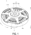
- FIG. 1 is a perspective view from above illustrating an overall configuration of an outer rotor-type motor according to an embodiment of the present invention.
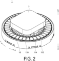
- FIG. 2 is a perspective view from below illustrating an overall configuration of an outer rotor-type motor according to an embodiment of the present invention.
- FIG. 3 is a perspective cross-sectional view of a motor according to an embodiment of the present invention.
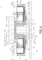
- FIG. 4 is a cross-sectional view of a motor according to an embodiment of the present invention.
- FIG. 5 is a perspective view illustrating a configuration of a holder of a motor according to an embodiment of the present invention.
- FIG. 6 is a cross-sectional view illustrating a configuration of a holder of a motor according to an embodiment of the present invention.
- FIG. 7 is a perspective view illustrating a configuration of a stator core of a motor according to an embodiment of the present invention.
- an extending direction of an axis X when a motor 1 rotates is referred to as an axial direction (rotational shaft direction) in the following description.
- an arrow a direction is referred to as an upper side or upward side
- an arrow b direction is referred to as a lower side or downward side.
- an arrow c direction away from the axis X is referred to as an outer peripheral side or an outer side
- an arrow d direction approaching the axis X is referred to as an inner peripheral side or an inner side.
- an arrow e direction is referred to as a clockwise direction
- an arrow f direction is referred to as a counterclockwise direction.
- the upper side (the arrow a direction) and the lower side (the arrow b direction) mean an up-down relationship of the motor 1 in the drawings, and do not necessarily correspond to an up-down relationship in the gravitational direction.
- the motor 1 is an outer rotor-type brushless motor to be mounted on a floating movable body, such as a drone (not illustrated), for example.
- the motor 1 includes a propeller (blade) 2 of a drone (see FIG. 4 ) attached to a rotor housing 17 at the upper side (the arrow a direction) and an aircraft body (external device) 3 of the drone attached to a holder 11 at the lower side (the arrow b direction).
- the motor 1 mainly includes the holder 11, a stator 13, a rotor 15, the rotor housing 17, a heat sink 18, and bearings 19.
- the holder 11 is a member made of, for example, a nonmagnetic material such as aluminum, and holding the stator 13 and the bearings 19. That is, the holder 11 functions as a holding part. As illustrated in FIGS. 3 to 6 , the holder 11 is a tubular member formed in a circular shape in a plan view.
- the holder 11 includes an inner wall part (first wall part) 111, an attachment part 112, an outer wall part (second wall part) 113, and a connection part 114.
- the inner wall part 111 is formed at the inner peripheral side (the arrow d direction) of the holder 11 in the radial direction.
- the inner wall part 111 is formed in an overall cylindrical shape or substantially cylindrical shape extending in the axis X direction.
- the inner wall part 111 holds two bearings 19 (19a, 19b) on a surface 111n at the inner peripheral side (the arrow d direction) (hereinafter, this surface is referred to as "inner peripheral surface").
- the two bearings 19 (19a, 19b) rotatably hold the rotor 15.
- the two bearings 19 (19a, 19b) are fitted into the inner peripheral surface 111n of the inner wall part 111 and fixed to the inner wall part 111 with an adhesive or the like.
- the means for fixing the two bearings 19 is not limited to the fitting and the adhesive, and outer rings of the bearings 19 may be press-fitted into and fixed to the inner peripheral surface 111n of the inner wall part 111.
- the inner wall part 111 functions as a bearing holder (bearing holding part) holding the two bearings 19.
- the bearings 19 are ball bearings, for example.
- the bearings 19 are not limited to the ball bearings, and any other various bearings such as a sleeve bearing may be used.
- An end part at the lower side (the arrow b direction) of the inner peripheral surface 111n of the inner wall part 111 has a larger inner diameter than inner diameters of other parts and includes a female screw groove 111s.
- An end part of the inner wall part 111 of the holder 11 at the opposite side to the rotor housing 17 (the lower side (the arrow b direction)) includes a pusher 12 formed in a thin-plate disk shape and fixed.
- the pusher 12 has a function to apply a preload to the bearings 19.
- the pusher 12 is fixed to the inner wall part 111 with an adhesive or the like with a surface at the outer peripheral side (the arrow c direction) in the radial direction (hereinafter, this surface is referred to as "outer peripheral surface”) screwed into the inner peripheral surface 111n of the inner wall part 111.
- a screw groove (male screw groove) 12s is formed in a surface at the outer peripheral side (the arrow c direction) of the pusher 12 in the radial direction, and the screw groove 12s is screwed into the female screw groove Ills formed in the inner peripheral surface 111n of the inner wall part 111.
- the pusher 12 includes a stepped part 12a at an end part at the outer peripheral side in the radial direction.
- the stepped part 12a supports the bearing 19a from the lower side (the arrow b direction).
- the attachment part 112 is a part to be attached with the aircraft body (external device) 3 of the drone.
- the attachment part 112 is provided at an end part at the lower side (the arrow b direction) of the inner wall part 111.
- the attachment part 112 is formed continuously at the inner wall part 111 and is integrally formed with the inner wall part 111. More specifically, the attachment part 112 is a part with the outer diameter of the end part at the lower side (the arrow b direction) of the inner wall part 111 enlarged toward the outer peripheral side (the arrow c direction). As illustrated in FIGS. 5 and 6 , the attachment part 112 is formed in an annular shape when viewed in a plan view.
- a plurality of holes 112h is formed extending along the axis X in the attachment part 112.
- the hole 112h is a hole for the passage of a fastener of a wiring line when the aircraft body 3 is attached, wind generated by the propeller 2, and the like.
- the attachment part 112 is formed in such a size that a surface opposing the aircraft body 3 is covered by the aircraft body 3.
- the attachment part 112 is formed with a predetermined height. Specifically, the attachment part 112 is formed extending in the axis X direction.
- the outer wall part 113 is formed at the outer peripheral side (the arrow c direction) of the holder 11 in the radial direction.
- the outer wall part 113 is formed in an overall cylindrical shape or substantially cylindrical shape extending in the axis X direction.
- the outer wall part 113 is formed continuously at the connection part 114 and is integrally formed with the connection part 114.
- the outer wall part 113 holds the stator 13 on a surface 113g at the outer peripheral side (the arrow c direction) (hereinafter, this surface is referred to as "outer peripheral surface").
- the connection part 114 may be constituted separately from the outer wall part 113 and the attachment part 112 and may be integrally formed with the outer wall part 113 and the attachment part 112 by using a fastening member or the like.
- the stator 13 is fitted into the outer peripheral surface 113g of the outer wall part 113 and is fixed to the outer wall part 113 with an adhesive or the like.
- the means for fixing the stator 13 is not limited to the fitting and the adhesive, and the stator 13 may be press-fitted into and fixed to the outer peripheral surface 113g of the outer wall part 113. That is, the outer wall part 113 functions as a contact part to be in contact with the stator 13.
- the outer diameter of the outer wall part 113 (the outer peripheral surface 113g) is approximately the same as an inner diameter of an inner peripheral surface 132n ( FIG. 7 ) of an annular part 132 of a stator core 131 described below.
- the outer diameter of the outer wall part 113 (the outer peripheral surface 113g) is not limited to the above configuration and may be slightly smaller than or slightly larger than the inner diameter of the inner peripheral surface 132n of the annular part 132.
- the outer wall part 113 has a function to hold the stator core 131, and a stator holding part is formed by the outer wall part 113.
- the outer wall part 113 is provided at the outer peripheral side (the arrow c direction) at a predetermined interval from the inner wall part 111. Similar to the inner wall part 111, the outer wall part 113 extends along the axis X direction.
- An end surface 113b at the lower side in the axis X direction (the arrow b direction) of the outer wall part 113 is arranged at the upper side in the axis X direction (the arrow a direction) relative to an end surface 112a at the upper side in the axis X direction (the arrow a direction) of the attachment part 112.
- the end surface 112a at one side in the axis X direction (the arrow a direction) of the attachment part 112 is arranged at the other side in the axis X direction (the arrow b direction) relative to the end surface 113b at the other side in the axis X direction (the arrow b direction) of the outer wall part 113.
- a space including neither the attachment part 112 nor the outer wall part 113 along the axis X direction is formed between the end surface 112a at the upper side in the axis X direction (the arrow a direction) of the attachment part 112 and the end surface 113b at the lower side in the axis X direction (the arrow b direction) of the outer wall part 113.
- the outer wall part 113 is formed with a larger outer diameter and inner diameter than the outer diameters and inner diameters of the inner wall part 111 and the attachment part 112.
- the inner diameter of the outer wall part 113 is formed to be larger than the outer diameters of the inner wall part 111 and the attachment part 112, and when the holder 11 is viewed in a plan view, a space is formed between an outer peripheral surface 111g of the inner wall part 111 and an outer peripheral surface 112g of the attachment part 112, and an inner peripheral surface 113n of the outer wall part 113.
- the end surface 113b at the lower side in the axis X direction (the arrow b direction) of the outer wall part 113 is arranged at the upper side in the axis X direction (the arrow a direction) relative to an end surface 139b at the lower side in the axis X direction (the arrow b direction) of a coil 139.
- the end surface 139b at the other side in the axis X direction (the arrow b direction) of the coil 139 is arranged at the other side in the axis X direction (the arrow b direction) relative to the end surface 113b at the other side in the axis X direction (the arrow b direction) of the outer wall part 113.
- connection part 114 is formed extending from the vicinity of the end part at the upper side in the axis X direction (the arrow a direction) of the outer peripheral surface 112g of the attachment part 112 toward the vicinity of the end part at the lower side in the axis X direction (the arrow b direction) of the inner peripheral surface 113n of the outer wall part 113.
- the connection part 114 is a part connecting the attachment part 112 and the outer wall part 113 and extends inclined toward the inner side in the radial direction relative to the axis X direction.
- connection part 114 intersects with the extending direction of the attachment part 112 and the outer wall part 113 (the axis X direction) and extends in an oblique direction approaching the inner peripheral side (the arrow d direction) toward the lower side in the axis X direction (the arrow b direction).
- a step in the axis X direction is provided between an end surface 112b at the lower side in the axis X direction (the arrow b direction) of the attachment part 112 and the end surface 113b at the lower side in the axis X direction (the arrow b direction) of the outer wall part 113.
- connection part 114 is integrally formed with the attachment part 112 with one end part (the end part at the lower side (the arrow b direction)) formed continuously at the attachment part 112.
- the connection part 114 is integrally formed with the outer wall part 113 with the other end part (the end part at the upper side (the arrow a direction)) being formed continuously at the outer wall part 113.
- connection parts 114 A plurality of the connection parts 114 is provided at predetermined intervals along the circumferential direction of the attachment part 112 and the outer wall part 113. Accordingly, an opening S is formed between the adjacent connection parts 114.
- the heat sink (cooling part) 18 is provided between the inner wall part 111 and the outer wall part 113.
- the heat sink 18 is provided at a position opposing the stator 13 in the radial direction.
- the heat sink 18 is formed in a plate shape and has a function to dissipate the heat in the motor 1.
- the heat sink 18 is provided at a position opposing the stator 13 via the outer wall part 113 in the radial direction.
- a part at the outer peripheral side is formed shorter than the outer wall part 113, but a part at the inner peripheral side is formed longer than the outer wall part 113.
- the part at the inner peripheral side of the heat sink 18 refers to a part opposing the attachment part 112 in the axis X direction. That is, part of the heat sink 18 includes a projecting part 18b projecting toward the lower side in the axis X direction (the arrow b direction), and the projecting part 18b opposes the attachment part 112.
- a plurality of the heat sinks 18 is provided at predetermined intervals along the circumferential direction of the inner wall part 111 and the outer wall part 113. Accordingly, a space is formed between the adjacent heat sinks 18.
- the shape of the heat sink 18 may be a rectangular shape where the lengths of a part at the outer peripheral side and a part at the inner peripheral side are equal or may be a shape having a part at the outer peripheral side shorter than a part at the inner peripheral side. It is sufficient to have a shape making contact with wind W passing through the interior of the motor 1.
- the stator 13 is fixed to the outer peripheral surface 113g of the outer wall part 113 of the holder 11.
- the stator 13 is provided at a position opposing the rotor 15, as illustrated in FIGS. 3 and 4 .
- the stator 13 includes the stator core 131 and the coil 139.
- the stator core 131 is a stacked body of silicon steel sheets or the like as a magnetic body.
- the stator core 131 includes the annular part 132, a tooth part 133, and a leading end part 134.
- a part including the tooth part 133 and the leading end part 134 is referred to as a magnetic pole part.
- the annular part 132 is an annular body formed in a circular shape in a plan view.
- the annular part 132 is formed with a predetermined thickness in the radial direction.
- the inner peripheral surface 132n (a side end surface at the inner diameter side of the stator 13 in the radial direction) of the annular part 132 is a part making contact with the outer peripheral surface 113g of the outer wall part 113 of the holder 11, and an outer peripheral surface 132g of the annular part 132 is a part with the tooth part 133 formed.
- the tooth part 133 is formed at the outer peripheral surface 132g of the annular part 132.
- the tooth part 133 is integrally formed with the annular part 132 in such a manner as to extend from the outer peripheral surface 132g of the annular part 132 toward the outer peripheral side (the side in the arrow c direction). That is, the tooth part 133 is formed extending along the radial direction of the annular part 132.
- a plurality of the tooth parts 133 is formed at a given interval along the circumferential direction of the outer peripheral surface 132g of the annular part 132.
- the leading end part 134 is formed at the leading end of each of the tooth parts 133.
- the leading end part 134 is integrally formed with the tooth part 133 projecting from the leading end of the tooth part 133 in the clockwise direction (the side in the arrow "e" direction) and in the counterclockwise direction (the side in the arrow "f' direction) of the annular part 132 in the circumferential direction.
- the leading end parts 134 are formed at a given interval in such a manner that the adjacent leading end parts 134 are not in contact with each other.
- the interval between the adjacent leading end parts 134 is narrower than a gap (slot) between the adjacent tooth parts 133.
- An insulator 138 (see FIG. 4 ) formed of an insulating member is mounted at the annular part 132 and the tooth part 133 of the stator core 131, and the coil 139 is wound via the insulator 138. That is, the annular part 132 and the tooth part 133 of the stator core 131 are electrically insulated from the coil 139 via the insulator 138.
- a resin film having an insulating property may be formed or applied on a surface of the stator core 131, and the resin film may be used as the insulator.
- the rotor 15 is formed in an annular shape.
- the rotor 15 includes a yoke 151 and a magnet 153.
- the yoke 151 is an iron core having a cylindrical shape extending along the axis X.
- the yoke 151 integrally holds the magnet 153 while surrounding the magnet 153.
- the yoke 151 forms the magnet 153 and a magnetic circuit and is formed of a magnetic body such as iron.
- the yoke 151 is formed higher in position than the magnet 153 in the axis X direction.
- the magnet 153 is an integrally molded product of a magnetic body.
- the magnet 153 similar to the yoke 151, has a cylindrical shape extending along the axis X.
- the magnet 153 is fixed to an inner peripheral surface 151n of the yoke 151 by using an adhesive.
- the magnet 153 may be held in contact with the inner peripheral surface 151n of the yoke 151 by not only the adhesive but also press-fitting, for example.
- An inner peripheral surface of the magnet 153 opposing the leading end part 134 of the stator core 131 is divided into a region magnetized to the south pole and a region magnetized to the north pole, and these magnetized regions are alternately arranged along the circumferential direction.
- the height of the magnet 153 in the axis X direction is formed lower than the height of the yoke 151 in the axis X direction.
- the height of the magnet 153 in the axis X direction may be formed equal to the height of the yoke 151 in the axis X direction.
- the magnet 153 it is sufficient for the magnet 153 to be held with an outer peripheral surface 153g of the magnet 153 covered by the yoke 151 from the outer peripheral side (the side in the arrow c direction).
- An outer peripheral part 173 (described below) of the rotor housing 17 is held by the inner peripheral surface 151n of the yoke 151 and an end surface 153a at the upper side (the arrow a direction) of the magnet 153.
- the rotor housing 17 is formed of a relatively light metal such as an aluminum alloy and has a disk shape on the whole. However, without being limited to the aluminum alloy, the rotor housing 17 may be formed of other materials such as resin and plastic. As illustrated in FIGS. 1 , 3 , and 4 , the rotor housing 17 includes an inner peripheral part 171, the outer peripheral part 173, and a spoke part 175.
- the inner peripheral part 171 is formed at the inner peripheral side (the arrow c direction) of the rotor housing 17.
- the inner peripheral part 171 is formed in a disk shape, and a hole 171h about the axis X is formed at the center.
- the inner peripheral part 171 has an outer diameter capable of covering the inner wall part 111 of the holder 11 from the upper side (the arrow a direction).
- the inner peripheral part 171 includes a rotational shaft 172 formed in a cylindrical shape extending in an up-down direction (the arrow a and b directions) about the axis X. Inner rings of the bearings 19 (19a, 19b) are held on an outer peripheral surface 172g of the rotational shaft 172. That is, the rotational shaft 172 rotates along with the rotor 15 in the motor 1.
- the rotational shaft 172 may have a columnar shape having no space at the inner peripheral side.
- the propeller 2 is attached to the rotational shaft 172 with bolts 2b. That is, the propeller 2 rotates along with the rotational shaft 172 in the motor 1.
- the outer peripheral part 173 is formed in an annular shape at the end part at the outer peripheral side (the arrow c direction) of the rotor housing 17.
- the outer peripheral part 173 is a part covering the magnet 153 fixed to the inner peripheral surface 151n of the yoke 151 from the upper side (the arrow a direction) by using the end part at the outer peripheral side (the arrow c direction) in the radial direction.
- the outer peripheral part 173 is pressure-fitted into the inner peripheral surface 151n of the yoke 151 to be integrally attached to the yoke 151, and an outer side surface 173m of the outer peripheral part 173 is in contact with the inner peripheral surface 151n of the yoke 151.
- the outer peripheral part 173 may be integrally attached to the yoke 151 by adhesion or the like to the inner peripheral surface 151n of the yoke 151.
- a plurality (for example, six) of the spoke parts 175 is formed and connects the inner peripheral part 171 and the outer peripheral part 173.
- One end part of the spoke part 175 is connected to an edge part at the outer peripheral side (the arrow c direction) of the inner peripheral part 171, and the other end part is connected to an edge part at the inner peripheral side (the arrow d direction) of the outer peripheral part 173.
- the inner peripheral part 171, the outer peripheral part 173, and the spoke part 175 are integrally formed.
- the holder 11 is inserted into the stator core 131 in such a manner as to set the inner peripheral surface 132n of the annular part 132 of the stator core 131 to be along the outer peripheral surface 113g of the outer wall part 113 of the holder 11.
- an adhesive is applied to the outer peripheral surface 113g of the outer wall part 113 of the holder 11.
- the outer peripheral surface 113g of the outer wall part 113 of the holder 11 and the inner peripheral surface 132n of the annular part 132 of the stator core 131 are brought into close contact with each other, and then the adhesive is dried.
- the stator core 131 is fixed to the holder 11.
- the pusher 12, the bearings 19, and the rotor housing 17 are attached to the inner wall part 111 of the holder 11.
- the propeller 2 attached to the rotor 15 also rotates about the axis X along with the rotational shaft 172.
- the wind W generated by the rotation of the propeller 2 flows toward the lower side (the arrow b direction) of the motor 1.
- the wind W passes through the opening S between the attachment part 112 and the outer wall part 113 and attempts to pass through toward the lower side (the arrow b direction) of the motor 1.
- the flow of the wind in the motor 1 is such that the wind W attempts to go out through the opening S before colliding with the attachment part 112, as indicated by arrows in FIG. 6 .
- the wind W reaches the opening S before reaching the end surface 112a at the upper side in the axis X direction (the arrow a direction) of the attachment part 112, the wind W easily passes through toward the lower side from the upper side of the motor 1 in such a manner as to prevent the collision with the aircraft body 3.
- This makes it possible to secure a sufficient flow rate and a sufficient flow volume.
- This enables the stay of the wind W within the motor 1 to be suppressed, and therefore the cooling efficiency of the motor 1 may be improved, and the heat generation of the motor 1 may be suppressed. Further, the efficiency of the motor 1 may be improved.
- connection part 114 is arranged being inclined toward the inner side in the radial direction relative to the axis X direction, it is possible to set a step in the axis X direction with the attachment part 112 and the outer wall part 113 as illustrated in FIG. 5 , and this step may be used as the opening S. Because the outer wall part 113 is formed at the outer side relative to the attachment part 112, a space may be formed between the outer peripheral surface 112g of the attachment part 112 and the inner peripheral surface 113n of the outer wall part 113, and a passage of the wind W may be secured even when the aircraft body 3 covers the entire region of the attachment part 112. Accordingly, the cooling of the motor 1 by the wind W is unlikely to be affected by the size of the aircraft body 3.
- connection parts 114 are arranged at intervals between each other along the circumferential direction of the attachment part 112 and the outer wall part 113, it is possible to form many passages of the wind W.
- the end surface 139b at the other side in the axis X direction (the arrow b direction) of the coil 139 is arranged at the other side in the axis X direction (the arrow b direction) relative to the end surface 113b at the other side in the axis X direction (the arrow b direction) of the outer wall part 113, and therefore the wind W passing through the opening S is also likely to hit the coil 139 so as to improve the cooling efficiency of the coil 139.
- the heat sink 18 opposes the stator 13 in the radial direction and opposes the attachment part 112 of the holder 11 in the axis X direction, and thus the heat sink 18 is arranged in the passage of the wind W. As a result, the heat of the heat sink 18 may be efficiently released to the outside by the wind W.
- the heat sink 18 opposes the stator 13 via the outer wall part 113, the heat of the stator 13 may be easily absorbed.
- the heat sink 18 includes the projecting part 18b projecting in the axis X direction, and the projecting part 18b opposes the attachment part 112 of the holder 11 in the axis X direction, the heat sink 18 may be increased in size as much as possible, and the cooling efficiency of the motor 1 may be improved.
- the motor is described with reference to the preferred embodiments, but the motor is not limited to the configurations of the embodiments described above.
- the above-described motor 1 is configured as an outer rotor-type brushless motor but is applicable also to a motor other than a brushless motor, and an inner rotor-type motor.
- the outer peripheral surface 112g of the attachment part 112 may be set to be an inclined surface inclined toward the inner side in the radial direction (the arrow d direction), toward the upper side in the axis X direction (the arrow a direction). This allows for increasing the size of the opening S between the attachment part 112 and the outer wall part 113 and improving the cooling efficiency of the motor 1, enabling the heat generation of the motor 1 to be suppressed.
- the inner peripheral surface 113n of the outer wall part 113 may be set to be an inclined surface inclined toward the outer side in the radial direction (the arrow c direction), toward the lower side in the axis X direction (the arrow b direction). This allows for increasing the size of the opening S between the attachment part 112 and the outer wall part 113 and improving the cooling efficiency of the motor 1, enabling the heat generation of the motor 1 to be suppressed.
- the inner wall part 111, the attachment part 112, the outer wall part 113, and the connection part 114 constituting the holder 11 may be integrally formed, or some of these parts may be separately formed.
- a disk-shaped rotor housing without the spoke part 175 may be used.
- the motor according to the present invention may be appropriately modified by a person skilled in the art according to conventionally known knowledge. Such modifications are of course included in the scope of the present invention as long as these modifications still include the configurations of the present invention.
Landscapes
- Engineering & Computer Science (AREA)
- Power Engineering (AREA)
- Motor Or Generator Frames (AREA)
- Motor Or Generator Cooling System (AREA)
- Permanent Magnet Type Synchronous Machine (AREA)
Applications Claiming Priority (1)
| Application Number | Priority Date | Filing Date | Title |
|---|---|---|---|
| JP2021163007A JP2023053770A (ja) | 2021-10-01 | 2021-10-01 | モータ |
Publications (1)
| Publication Number | Publication Date |
|---|---|
| EP4160872A1 true EP4160872A1 (en) | 2023-04-05 |
Family
ID=83505819
Family Applications (1)
| Application Number | Title | Priority Date | Filing Date |
|---|---|---|---|
| EP22198563.3A Pending EP4160872A1 (en) | 2021-10-01 | 2022-09-29 | Motor |
Country Status (4)
| Country | Link |
|---|---|
| US (1) | US20230108449A1 (ja) |
| EP (1) | EP4160872A1 (ja) |
| JP (1) | JP2023053770A (ja) |
| CN (1) | CN115940483A (ja) |
Citations (2)
| Publication number | Priority date | Publication date | Assignee | Title |
|---|---|---|---|---|
| JP2019068604A (ja) | 2017-09-29 | 2019-04-25 | 日本電産サーボ株式会社 | モータ |
| EP3605802A1 (en) * | 2017-09-20 | 2020-02-05 | Shinano Kenshi Kabushiki Kaisha | All-weather motor |
-
2021
- 2021-10-01 JP JP2021163007A patent/JP2023053770A/ja active Pending
-
2022
- 2022-07-05 CN CN202210791064.2A patent/CN115940483A/zh active Pending
- 2022-09-22 US US17/934,219 patent/US20230108449A1/en active Pending
- 2022-09-29 EP EP22198563.3A patent/EP4160872A1/en active Pending
Patent Citations (2)
| Publication number | Priority date | Publication date | Assignee | Title |
|---|---|---|---|---|
| EP3605802A1 (en) * | 2017-09-20 | 2020-02-05 | Shinano Kenshi Kabushiki Kaisha | All-weather motor |
| JP2019068604A (ja) | 2017-09-29 | 2019-04-25 | 日本電産サーボ株式会社 | モータ |
Also Published As
| Publication number | Publication date |
|---|---|
| CN115940483A (zh) | 2023-04-07 |
| US20230108449A1 (en) | 2023-04-06 |
| JP2023053770A (ja) | 2023-04-13 |
Similar Documents
| Publication | Publication Date | Title |
|---|---|---|
| US9033680B2 (en) | Electric fan | |
| JP4904894B2 (ja) | 軸流ファン | |
| US20190128280A1 (en) | Centrifugal fan | |
| CN109314435B (zh) | 无人机电机及包括该无人机电机的无人机 | |
| US11022128B2 (en) | Axial fan | |
| US20180291914A1 (en) | Fan motor | |
| EP4160872A1 (en) | Motor | |
| EP3496235B1 (en) | Motor | |
| EP3496239B1 (en) | Motor | |
| WO2020202390A1 (ja) | アウタロータ型モータ | |
| JP6950422B2 (ja) | 遠心ファン | |
| US20090246043A1 (en) | Fan motor | |
| US20190036403A1 (en) | Motor | |
| US20220316487A1 (en) | Rotating device | |
| US11002312B2 (en) | Motor and fan motor | |
| JP2019180201A (ja) | モータ及び送風装置 | |
| WO2018025987A1 (ja) | モータ | |
| JP2019180141A (ja) | モータ | |
| EP3364527B1 (en) | Electric motor and blower | |
| US20230107866A1 (en) | Motor | |
| US20220278577A1 (en) | Motor | |
| JP6399070B2 (ja) | 回転電機 | |
| US11215185B2 (en) | Axial fan | |
| US11892033B2 (en) | Motor | |
| US20230216380A1 (en) | Stator assembly for electronically switched electric motor |
Legal Events
| Date | Code | Title | Description |
|---|---|---|---|
| PUAI | Public reference made under article 153(3) epc to a published international application that has entered the european phase |
Free format text: ORIGINAL CODE: 0009012 |
|
| STAA | Information on the status of an ep patent application or granted ep patent |
Free format text: STATUS: THE APPLICATION HAS BEEN PUBLISHED |
|
| AK | Designated contracting states |
Kind code of ref document: A1 Designated state(s): AL AT BE BG CH CY CZ DE DK EE ES FI FR GB GR HR HU IE IS IT LI LT LU LV MC MK MT NL NO PL PT RO RS SE SI SK SM TR |
|
| STAA | Information on the status of an ep patent application or granted ep patent |
Free format text: STATUS: REQUEST FOR EXAMINATION WAS MADE |
|
| 17P | Request for examination filed |
Effective date: 20230929 |
|
| RBV | Designated contracting states (corrected) |
Designated state(s): AL AT BE BG CH CY CZ DE DK EE ES FI FR GB GR HR HU IE IS IT LI LT LU LV MC MK MT NL NO PL PT RO RS SE SI SK SM TR |