EP4160047A2 - Ensembles d'engrenages et appareil - Google Patents
Ensembles d'engrenages et appareil Download PDFInfo
- Publication number
- EP4160047A2 EP4160047A2 EP22209358.5A EP22209358A EP4160047A2 EP 4160047 A2 EP4160047 A2 EP 4160047A2 EP 22209358 A EP22209358 A EP 22209358A EP 4160047 A2 EP4160047 A2 EP 4160047A2
- Authority
- EP
- European Patent Office
- Prior art keywords
- gearing
- shift
- dog
- arrangement
- hub
- Prior art date
- Legal status (The legal status is an assumption and is not a legal conclusion. Google has not performed a legal analysis and makes no representation as to the accuracy of the status listed.)
- Pending
Links
- 230000000712 assembly Effects 0.000 title description 9
- 238000000429 assembly Methods 0.000 title description 9
- 230000000694 effects Effects 0.000 claims abstract description 5
- 230000007246 mechanism Effects 0.000 claims description 4
- 230000001419 dependent effect Effects 0.000 claims 1
- 230000009467 reduction Effects 0.000 description 13
- 238000002955 isolation Methods 0.000 description 3
- 230000000295 complement effect Effects 0.000 description 2
- 238000010276 construction Methods 0.000 description 2
- 230000009471 action Effects 0.000 description 1
- 230000005540 biological transmission Effects 0.000 description 1
- 230000008859 change Effects 0.000 description 1
- 239000000446 fuel Substances 0.000 description 1
- 238000003754 machining Methods 0.000 description 1
- 230000013011 mating Effects 0.000 description 1
- 230000007935 neutral effect Effects 0.000 description 1
Images


Classifications
-
- B—PERFORMING OPERATIONS; TRANSPORTING
- B60—VEHICLES IN GENERAL
- B60K—ARRANGEMENT OR MOUNTING OF PROPULSION UNITS OR OF TRANSMISSIONS IN VEHICLES; ARRANGEMENT OR MOUNTING OF PLURAL DIVERSE PRIME-MOVERS IN VEHICLES; AUXILIARY DRIVES FOR VEHICLES; INSTRUMENTATION OR DASHBOARDS FOR VEHICLES; ARRANGEMENTS IN CONNECTION WITH COOLING, AIR INTAKE, GAS EXHAUST OR FUEL SUPPLY OF PROPULSION UNITS IN VEHICLES
- B60K7/00—Disposition of motor in, or adjacent to, traction wheel
- B60K7/0007—Disposition of motor in, or adjacent to, traction wheel the motor being electric
-
- B—PERFORMING OPERATIONS; TRANSPORTING
- B60—VEHICLES IN GENERAL
- B60K—ARRANGEMENT OR MOUNTING OF PROPULSION UNITS OR OF TRANSMISSIONS IN VEHICLES; ARRANGEMENT OR MOUNTING OF PLURAL DIVERSE PRIME-MOVERS IN VEHICLES; AUXILIARY DRIVES FOR VEHICLES; INSTRUMENTATION OR DASHBOARDS FOR VEHICLES; ARRANGEMENTS IN CONNECTION WITH COOLING, AIR INTAKE, GAS EXHAUST OR FUEL SUPPLY OF PROPULSION UNITS IN VEHICLES
- B60K17/00—Arrangement or mounting of transmissions in vehicles
- B60K17/02—Arrangement or mounting of transmissions in vehicles characterised by arrangement, location, or kind of clutch
-
- B—PERFORMING OPERATIONS; TRANSPORTING
- B60—VEHICLES IN GENERAL
- B60K—ARRANGEMENT OR MOUNTING OF PROPULSION UNITS OR OF TRANSMISSIONS IN VEHICLES; ARRANGEMENT OR MOUNTING OF PLURAL DIVERSE PRIME-MOVERS IN VEHICLES; AUXILIARY DRIVES FOR VEHICLES; INSTRUMENTATION OR DASHBOARDS FOR VEHICLES; ARRANGEMENTS IN CONNECTION WITH COOLING, AIR INTAKE, GAS EXHAUST OR FUEL SUPPLY OF PROPULSION UNITS IN VEHICLES
- B60K17/00—Arrangement or mounting of transmissions in vehicles
- B60K17/04—Arrangement or mounting of transmissions in vehicles characterised by arrangement, location or kind of gearing
- B60K17/043—Transmission unit disposed in on near the vehicle wheel, or between the differential gear unit and the wheel
- B60K17/046—Transmission unit disposed in on near the vehicle wheel, or between the differential gear unit and the wheel with planetary gearing having orbital motion
-
- B—PERFORMING OPERATIONS; TRANSPORTING
- B60—VEHICLES IN GENERAL
- B60K—ARRANGEMENT OR MOUNTING OF PROPULSION UNITS OR OF TRANSMISSIONS IN VEHICLES; ARRANGEMENT OR MOUNTING OF PLURAL DIVERSE PRIME-MOVERS IN VEHICLES; AUXILIARY DRIVES FOR VEHICLES; INSTRUMENTATION OR DASHBOARDS FOR VEHICLES; ARRANGEMENTS IN CONNECTION WITH COOLING, AIR INTAKE, GAS EXHAUST OR FUEL SUPPLY OF PROPULSION UNITS IN VEHICLES
- B60K17/00—Arrangement or mounting of transmissions in vehicles
- B60K17/04—Arrangement or mounting of transmissions in vehicles characterised by arrangement, location or kind of gearing
- B60K17/06—Arrangement or mounting of transmissions in vehicles characterised by arrangement, location or kind of gearing of change-speed gearing
- B60K17/08—Arrangement or mounting of transmissions in vehicles characterised by arrangement, location or kind of gearing of change-speed gearing of mechanical type
-
- F—MECHANICAL ENGINEERING; LIGHTING; HEATING; WEAPONS; BLASTING
- F16—ENGINEERING ELEMENTS AND UNITS; GENERAL MEASURES FOR PRODUCING AND MAINTAINING EFFECTIVE FUNCTIONING OF MACHINES OR INSTALLATIONS; THERMAL INSULATION IN GENERAL
- F16D—COUPLINGS FOR TRANSMITTING ROTATION; CLUTCHES; BRAKES
- F16D11/00—Clutches in which the members have interengaging parts
- F16D11/08—Clutches in which the members have interengaging parts actuated by moving a non-rotating part axially
- F16D11/10—Clutches in which the members have interengaging parts actuated by moving a non-rotating part axially with clutching members movable only axially
-
- F—MECHANICAL ENGINEERING; LIGHTING; HEATING; WEAPONS; BLASTING
- F16—ENGINEERING ELEMENTS AND UNITS; GENERAL MEASURES FOR PRODUCING AND MAINTAINING EFFECTIVE FUNCTIONING OF MACHINES OR INSTALLATIONS; THERMAL INSULATION IN GENERAL
- F16D—COUPLINGS FOR TRANSMITTING ROTATION; CLUTCHES; BRAKES
- F16D11/00—Clutches in which the members have interengaging parts
- F16D11/14—Clutches in which the members have interengaging parts with clutching members movable only axially
-
- F—MECHANICAL ENGINEERING; LIGHTING; HEATING; WEAPONS; BLASTING
- F16—ENGINEERING ELEMENTS AND UNITS; GENERAL MEASURES FOR PRODUCING AND MAINTAINING EFFECTIVE FUNCTIONING OF MACHINES OR INSTALLATIONS; THERMAL INSULATION IN GENERAL
- F16D—COUPLINGS FOR TRANSMITTING ROTATION; CLUTCHES; BRAKES
- F16D21/00—Systems comprising a plurality of actuated clutches
- F16D21/02—Systems comprising a plurality of actuated clutches for interconnecting three or more shafts or other transmission members in different ways
- F16D21/04—Systems comprising a plurality of actuated clutches for interconnecting three or more shafts or other transmission members in different ways with a shaft carrying a number of rotatable transmission members, e.g. gears, each of which can be connected to the shaft by a clutching member or members between the shaft and the hub of the transmission member
-
- F—MECHANICAL ENGINEERING; LIGHTING; HEATING; WEAPONS; BLASTING
- F16—ENGINEERING ELEMENTS AND UNITS; GENERAL MEASURES FOR PRODUCING AND MAINTAINING EFFECTIVE FUNCTIONING OF MACHINES OR INSTALLATIONS; THERMAL INSULATION IN GENERAL
- F16H—GEARING
- F16H3/00—Toothed gearings for conveying rotary motion with variable gear ratio or for reversing rotary motion
- F16H3/44—Toothed gearings for conveying rotary motion with variable gear ratio or for reversing rotary motion using gears having orbital motion
- F16H3/62—Gearings having three or more central gears
- F16H3/66—Gearings having three or more central gears composed of a number of gear trains without drive passing from one train to another
-
- F—MECHANICAL ENGINEERING; LIGHTING; HEATING; WEAPONS; BLASTING
- F16—ENGINEERING ELEMENTS AND UNITS; GENERAL MEASURES FOR PRODUCING AND MAINTAINING EFFECTIVE FUNCTIONING OF MACHINES OR INSTALLATIONS; THERMAL INSULATION IN GENERAL
- F16H—GEARING
- F16H63/00—Control outputs from the control unit to change-speed- or reversing-gearings for conveying rotary motion or to other devices than the final output mechanism
- F16H63/02—Final output mechanisms therefor; Actuating means for the final output mechanisms
- F16H63/30—Constructional features of the final output mechanisms
-
- B—PERFORMING OPERATIONS; TRANSPORTING
- B60—VEHICLES IN GENERAL
- B60K—ARRANGEMENT OR MOUNTING OF PROPULSION UNITS OR OF TRANSMISSIONS IN VEHICLES; ARRANGEMENT OR MOUNTING OF PLURAL DIVERSE PRIME-MOVERS IN VEHICLES; AUXILIARY DRIVES FOR VEHICLES; INSTRUMENTATION OR DASHBOARDS FOR VEHICLES; ARRANGEMENTS IN CONNECTION WITH COOLING, AIR INTAKE, GAS EXHAUST OR FUEL SUPPLY OF PROPULSION UNITS IN VEHICLES
- B60K7/00—Disposition of motor in, or adjacent to, traction wheel
- B60K2007/0038—Disposition of motor in, or adjacent to, traction wheel the motor moving together with the wheel axle
-
- B—PERFORMING OPERATIONS; TRANSPORTING
- B60—VEHICLES IN GENERAL
- B60K—ARRANGEMENT OR MOUNTING OF PROPULSION UNITS OR OF TRANSMISSIONS IN VEHICLES; ARRANGEMENT OR MOUNTING OF PLURAL DIVERSE PRIME-MOVERS IN VEHICLES; AUXILIARY DRIVES FOR VEHICLES; INSTRUMENTATION OR DASHBOARDS FOR VEHICLES; ARRANGEMENTS IN CONNECTION WITH COOLING, AIR INTAKE, GAS EXHAUST OR FUEL SUPPLY OF PROPULSION UNITS IN VEHICLES
- B60K7/00—Disposition of motor in, or adjacent to, traction wheel
- B60K2007/0092—Disposition of motor in, or adjacent to, traction wheel the motor axle being coaxial to the wheel axle
-
- B—PERFORMING OPERATIONS; TRANSPORTING
- B60—VEHICLES IN GENERAL
- B60Y—INDEXING SCHEME RELATING TO ASPECTS CROSS-CUTTING VEHICLE TECHNOLOGY
- B60Y2400/00—Special features of vehicle units
- B60Y2400/42—Clutches or brakes
- B60Y2400/421—Dog type clutches or brakes
-
- F—MECHANICAL ENGINEERING; LIGHTING; HEATING; WEAPONS; BLASTING
- F16—ENGINEERING ELEMENTS AND UNITS; GENERAL MEASURES FOR PRODUCING AND MAINTAINING EFFECTIVE FUNCTIONING OF MACHINES OR INSTALLATIONS; THERMAL INSULATION IN GENERAL
- F16D—COUPLINGS FOR TRANSMITTING ROTATION; CLUTCHES; BRAKES
- F16D11/00—Clutches in which the members have interengaging parts
- F16D2011/004—Clutches in which the members have interengaging parts using an internal or intermediate axially slidable sleeve, coupling both components together, whereby the intermediate sleeve is arranged internally at least with respect to one of the components
-
- F—MECHANICAL ENGINEERING; LIGHTING; HEATING; WEAPONS; BLASTING
- F16—ENGINEERING ELEMENTS AND UNITS; GENERAL MEASURES FOR PRODUCING AND MAINTAINING EFFECTIVE FUNCTIONING OF MACHINES OR INSTALLATIONS; THERMAL INSULATION IN GENERAL
- F16D—COUPLINGS FOR TRANSMITTING ROTATION; CLUTCHES; BRAKES
- F16D11/00—Clutches in which the members have interengaging parts
- F16D2011/006—Locking or detent means, i.e. means to keep the clutch in engaged condition
-
- F—MECHANICAL ENGINEERING; LIGHTING; HEATING; WEAPONS; BLASTING
- F16—ENGINEERING ELEMENTS AND UNITS; GENERAL MEASURES FOR PRODUCING AND MAINTAINING EFFECTIVE FUNCTIONING OF MACHINES OR INSTALLATIONS; THERMAL INSULATION IN GENERAL
- F16H—GEARING
- F16H63/00—Control outputs from the control unit to change-speed- or reversing-gearings for conveying rotary motion or to other devices than the final output mechanism
- F16H63/02—Final output mechanisms therefor; Actuating means for the final output mechanisms
- F16H63/30—Constructional features of the final output mechanisms
- F16H2063/3093—Final output elements, i.e. the final elements to establish gear ratio, e.g. dog clutches or other means establishing coupling to shaft
-
- F—MECHANICAL ENGINEERING; LIGHTING; HEATING; WEAPONS; BLASTING
- F16—ENGINEERING ELEMENTS AND UNITS; GENERAL MEASURES FOR PRODUCING AND MAINTAINING EFFECTIVE FUNCTIONING OF MACHINES OR INSTALLATIONS; THERMAL INSULATION IN GENERAL
- F16H—GEARING
- F16H2200/00—Transmissions for multiple ratios
- F16H2200/0021—Transmissions for multiple ratios specially adapted for electric vehicles
-
- F—MECHANICAL ENGINEERING; LIGHTING; HEATING; WEAPONS; BLASTING
- F16—ENGINEERING ELEMENTS AND UNITS; GENERAL MEASURES FOR PRODUCING AND MAINTAINING EFFECTIVE FUNCTIONING OF MACHINES OR INSTALLATIONS; THERMAL INSULATION IN GENERAL
- F16H—GEARING
- F16H2200/00—Transmissions for multiple ratios
- F16H2200/003—Transmissions for multiple ratios characterised by the number of forward speeds
- F16H2200/0034—Transmissions for multiple ratios characterised by the number of forward speeds the gear ratios comprising two forward speeds
-
- F—MECHANICAL ENGINEERING; LIGHTING; HEATING; WEAPONS; BLASTING
- F16—ENGINEERING ELEMENTS AND UNITS; GENERAL MEASURES FOR PRODUCING AND MAINTAINING EFFECTIVE FUNCTIONING OF MACHINES OR INSTALLATIONS; THERMAL INSULATION IN GENERAL
- F16H—GEARING
- F16H2200/00—Transmissions for multiple ratios
- F16H2200/003—Transmissions for multiple ratios characterised by the number of forward speeds
- F16H2200/0039—Transmissions for multiple ratios characterised by the number of forward speeds the gear ratios comprising three forward speeds
-
- F—MECHANICAL ENGINEERING; LIGHTING; HEATING; WEAPONS; BLASTING
- F16—ENGINEERING ELEMENTS AND UNITS; GENERAL MEASURES FOR PRODUCING AND MAINTAINING EFFECTIVE FUNCTIONING OF MACHINES OR INSTALLATIONS; THERMAL INSULATION IN GENERAL
- F16H—GEARING
- F16H2200/00—Transmissions for multiple ratios
- F16H2200/20—Transmissions using gears with orbital motion
- F16H2200/2002—Transmissions using gears with orbital motion characterised by the number of sets of orbital gears
- F16H2200/2007—Transmissions using gears with orbital motion characterised by the number of sets of orbital gears with two sets of orbital gears
-
- F—MECHANICAL ENGINEERING; LIGHTING; HEATING; WEAPONS; BLASTING
- F16—ENGINEERING ELEMENTS AND UNITS; GENERAL MEASURES FOR PRODUCING AND MAINTAINING EFFECTIVE FUNCTIONING OF MACHINES OR INSTALLATIONS; THERMAL INSULATION IN GENERAL
- F16H—GEARING
- F16H2200/00—Transmissions for multiple ratios
- F16H2200/20—Transmissions using gears with orbital motion
- F16H2200/2002—Transmissions using gears with orbital motion characterised by the number of sets of orbital gears
- F16H2200/201—Transmissions using gears with orbital motion characterised by the number of sets of orbital gears with three sets of orbital gears
-
- F—MECHANICAL ENGINEERING; LIGHTING; HEATING; WEAPONS; BLASTING
- F16—ENGINEERING ELEMENTS AND UNITS; GENERAL MEASURES FOR PRODUCING AND MAINTAINING EFFECTIVE FUNCTIONING OF MACHINES OR INSTALLATIONS; THERMAL INSULATION IN GENERAL
- F16H—GEARING
- F16H2200/00—Transmissions for multiple ratios
- F16H2200/20—Transmissions using gears with orbital motion
- F16H2200/2002—Transmissions using gears with orbital motion characterised by the number of sets of orbital gears
- F16H2200/2012—Transmissions using gears with orbital motion characterised by the number of sets of orbital gears with four sets of orbital gears
-
- F—MECHANICAL ENGINEERING; LIGHTING; HEATING; WEAPONS; BLASTING
- F16—ENGINEERING ELEMENTS AND UNITS; GENERAL MEASURES FOR PRODUCING AND MAINTAINING EFFECTIVE FUNCTIONING OF MACHINES OR INSTALLATIONS; THERMAL INSULATION IN GENERAL
- F16H—GEARING
- F16H2200/00—Transmissions for multiple ratios
- F16H2200/20—Transmissions using gears with orbital motion
- F16H2200/203—Transmissions using gears with orbital motion characterised by the engaging friction means not of the freewheel type, e.g. friction clutches or brakes
- F16H2200/2038—Transmissions using gears with orbital motion characterised by the engaging friction means not of the freewheel type, e.g. friction clutches or brakes with three engaging means
-
- F—MECHANICAL ENGINEERING; LIGHTING; HEATING; WEAPONS; BLASTING
- F16—ENGINEERING ELEMENTS AND UNITS; GENERAL MEASURES FOR PRODUCING AND MAINTAINING EFFECTIVE FUNCTIONING OF MACHINES OR INSTALLATIONS; THERMAL INSULATION IN GENERAL
- F16H—GEARING
- F16H2200/00—Transmissions for multiple ratios
- F16H2200/20—Transmissions using gears with orbital motion
- F16H2200/203—Transmissions using gears with orbital motion characterised by the engaging friction means not of the freewheel type, e.g. friction clutches or brakes
- F16H2200/2064—Transmissions using gears with orbital motion characterised by the engaging friction means not of the freewheel type, e.g. friction clutches or brakes using at least one positive clutch, e.g. dog clutch
-
- F—MECHANICAL ENGINEERING; LIGHTING; HEATING; WEAPONS; BLASTING
- F16—ENGINEERING ELEMENTS AND UNITS; GENERAL MEASURES FOR PRODUCING AND MAINTAINING EFFECTIVE FUNCTIONING OF MACHINES OR INSTALLATIONS; THERMAL INSULATION IN GENERAL
- F16H—GEARING
- F16H2200/00—Transmissions for multiple ratios
- F16H2200/20—Transmissions using gears with orbital motion
- F16H2200/2094—Transmissions using gears with orbital motion using positive clutches, e.g. dog clutches
-
- F—MECHANICAL ENGINEERING; LIGHTING; HEATING; WEAPONS; BLASTING
- F16—ENGINEERING ELEMENTS AND UNITS; GENERAL MEASURES FOR PRODUCING AND MAINTAINING EFFECTIVE FUNCTIONING OF MACHINES OR INSTALLATIONS; THERMAL INSULATION IN GENERAL
- F16H—GEARING
- F16H2200/00—Transmissions for multiple ratios
- F16H2200/20—Transmissions using gears with orbital motion
- F16H2200/2097—Transmissions using gears with orbital motion comprising an orbital gear set member permanently connected to the housing, e.g. a sun wheel permanently connected to the housing
-
- Y—GENERAL TAGGING OF NEW TECHNOLOGICAL DEVELOPMENTS; GENERAL TAGGING OF CROSS-SECTIONAL TECHNOLOGIES SPANNING OVER SEVERAL SECTIONS OF THE IPC; TECHNICAL SUBJECTS COVERED BY FORMER USPC CROSS-REFERENCE ART COLLECTIONS [XRACs] AND DIGESTS
- Y02—TECHNOLOGIES OR APPLICATIONS FOR MITIGATION OR ADAPTATION AGAINST CLIMATE CHANGE
- Y02T—CLIMATE CHANGE MITIGATION TECHNOLOGIES RELATED TO TRANSPORTATION
- Y02T10/00—Road transport of goods or passengers
- Y02T10/60—Other road transportation technologies with climate change mitigation effect
- Y02T10/62—Hybrid vehicles
Definitions
- This invention relates to gearing assemblies and apparatus.
- Gearing assemblies and apparatus of the present kind may be found useful in a variety of vehicular applications or in other machinery where a simple robust and compact gearbox is useful. Gearing assemblies are used commonly on vehicles where it is desired to drive a wheel or axle at a different rotational speed to the revolutions of an engine or motor. Assemblies of the present kind may find a particular application in a gearing system for an electrical hub drive and applications of the present systems are discussed herein in that context by way of example, although it should be noted that the invention is not limited to such applications.
- Electric hub drive or hub mounted electric drive (HMED) units are finding increasing use in vehicles where it is advantageous for the wheels to be driven independently. Applications include, for example large vehicles and vehicles adapted for use on difficult, for example steep and uneven, terrain. HMED units are finding increasing use on hybrid vehicles. HMED units are finding increasing use on military vehicles particularly for use on difficult terrain.
- each wheel is provided with a hub mounted electric drive assembly, typically comprising a housing containing an electric motor and a drive train including a drive shaft arranged inside a suitable hub mounted housing.
- An output shaft of the hub drive drives the wheel.
- the hub drive assembly can fit at least partly within space available inside the diameter and the overall width of the wheel rim and tyre assembly, in at least some cases.
- the use of individual hub mounted electric drive units can eliminate the need for conventional transmission and drive shafts and can offer enhanced vehicle capabilities through improvements in vehicle performance, fuel economy, design configuration, increased stealth capability and reduced whole of life costs.
- an electric hub drive will be such that it needs to have a large torque range and a large speed range as well as desirably being compact.
- a multispeed gear change mechanism is desirable to facilitate this.
- Higher gear ratios can be used to provide higher torques at lower speeds and lower gear ratios can be used to allow for higher speeds (with low available output torque).
- gearing assemblies and apparatus for, amongst other things, use in such units, it is desirable if a compact design can be achieved and if there is flexibility in terms of the positioning of various parts of the gearing assembly and/or apparatus necessary to provide the different gear changes and where appropriate, flexibility for positioning controls operable by a user for controlling those gear changes.
- gearing assembly is shown in WO2016/146628 .
- three different gears are provided.
- Two of the gears are selectable by use of a first shift fork provided on one side of the motor using first and second dog clutches.
- the dog clutches operate using mutually engageable axially extending teeth such that in order to engage the clutch, a dog hub carrying axially extending teeth is moved axially into engagement with corresponding teeth on the remainder of the clutch and in order to disengage the clutch, the dog hub is moved in the axially opposite direction.
- axial movement of the dog hub to its maximum extent in one direction engages a first dog clutch whereas axial movement of the dog hub in the opposite axial direction to the maximum extent engages a second dog clutch.
- a third dog clutch and a second shift fork for operating the third clutch are provided on the other side of the motor.
- gearing assemblies and apparatus which provide more flexibility in design and, for example can allow the provision of a more compact design and/or allow a choice of position for a shift fork associated with a respective clutch.
- a gearing assembly comprising a rotary input member, a rotary output member and a gearing arrangement between the input member and the output member selectively engageable to effect a driving engagement between the input member and the output member through at least a first torque connection having a first gear ratio and a second torque connection having a second gear ratio,
- This arrangement allows the dog hub to pass through the dog ring so allowing a greater flexibility in the way that the gearing assembly can be arranged. This is because the dog hub may be moved axially in both directions away from the engaged position. This contrasts with the conventional dog clutches used in preexisting systems which do not allow the dog hub to pass through an engaged position such as to allow only axial movement in one way away from the engaged position.
- the dog hub being moveable into and out of engagement with the dog ring of the dog clutch of the first torque connection it may be moved to a position allowing use of a second torque connection, or a third torque connection, or even a higher number of independent connections.
- those connections might be via the same set of dog teeth on the dog hub or via a different set of teeth on the same dog hub, or via a different dog hub, or using a different type of clutch, or so on.
- the second torque connection may comprise a second dog clutch comprising a respective dog hub comprising a respective hub set of teeth and a respective surrounding dog ring comprising a respective ring set of teeth, the respective hub and ring sets of teeth being radially projecting and mutually engageable.
- the dog hub of the second dog clutch may be the same dog hub as the dog hub of the first dog clutch - to put this another way the first and second dog clutches may share a common dog hub.
- the dog hub will be moveable between the first engaged position in which driving engagement between the input member and the output member is effected through the first torque connection and a second engaged position in which driving engagement between the input member and the output member is effected through the second torque connection.
- the dog hub may have a common hub set of teeth for selective engagement with the ring set of teeth of the first dog clutch and the ring set of teeth of a second dog clutch.
- the dog hub may comprise a first hub set of teeth for selective engagement with the ring set of teeth of the first dog clutch and a second hub set of teeth for selective engagement with the ring set of teeth of a second dog clutch.
- the gearing assembly may comprise a plurality of dog hubs.
- the first torque connection may comprise a first dog hub.
- the second torque connection may comprise a second dog hub which is independent of the first dog hub.
- the gearing assembly may comprise a plurality of clutches, say dog clutches, each associated with a respective torque connection.
- the gearing assembly may comprise a plurality of dog clutches each of which comprises a dog hub comprising a hub set of teeth and a surrounding dog ring comprising a ring set of teeth, the hub and ring sets of teeth being radially projecting and mutually engageable, and each of these may have the same overall construction as the first dog clutch.
- At least one second or subsequent clutch may have a different construction from the first dog clutch.
- the at least one second or subsequent clutch may comprise a dog hub with axially extending teeth.
- the gearing assembly may comprise a gearing arrangement between the input member and the output member selectively engageable to effect a driving engagement between the input member and the output member through at least a first torque connection having a first gear ratio, a second torque connection having a second gear ratio, and a third torque connection having a third gear ratio, wherein the first torque connection comprises a first dog clutch, the second torque connection comprises a second dog clutch, and the third torque connection comprises a third dog clutch.
- the first, second, and third dog clutches comprise a common dog hub which is arranged for movement axially between the first engaged position in which driving engagement between the input member and the output member is effected through the first torque connection, a second engaged position in which driving engagement between the input member and the output member is effected through the second torque connection, and a third engaged position in which driving engagement between the input member and the output member is effected through the third torque connection, wherein the first engaged position is axially between the second engaged position and the third engaged position.
- the common dog hub may comprise a common set of hub teeth which is for selective engagement with the dog ring of the first dog clutch and respective dog rings of the second dog clutch and the third dog clutch.
- each dog clutch may be of the same overall design as the first dog clutch and for example the common hub set of teeth may be arranged so as to be able to pass through respective ring sets of teeth on each dog ring.
- the second and/or third dog clutch may be of a different kind than the first dog clutch.
- the common dog hub may comprise two or more hub sets of teeth each for engaging with a corresponding remaining portion of at least one of the first, second, and third dog clutch.
- the second and/or third dog clutch may be arranged so as to not allow the dog hub to pass through a respective engaged position such as to allow only axial movement in one way away from the engaged position.
- the second and/or third dog clutch may comprise axially extending dog teeth for achieving driving engagement between the dog hub and the remainder of the respective dog clutch.
- the dog teeth may comprise teeth provided on an axially facing face of the dog hub.
- At least one of the dog clutches may be arranged to withstand a differing level of torque from at least another of the dog clutches.
- At least one of the dog clutches may have a different diameter than at least one other of the dog clutches. This can help give higher torque transfer capability for gear ratios giving lower output speed, whilst minimising the space occupied by a dog clutch which is to carry drive at higher output speeds.
- the first shaft and the dog hub may be provided with mutually engaging splines for mounting the dog hub on the shaft so as to allow relative axial movement whilst resisting relative rotational movement.
- the or each dog ring may act as an output (or an input) of the gearing arrangement.
- the gearing arrangement may comprise a planetary gear stage.
- the gearing arrangement which may comprise a planetary gear stage, may comprise at least one sun gear, which sun gear may comprise the dog ring of the first dog clutch.
- the planetary gear stage may comprise a respective planetary gear carrier, which carrier may comprise the dog ring of the first dog clutch.
- the gearing arrangement may comprise a plurality of planetary gear stages.
- Each planetary gear stage may comprise a sun gear, which sun gear comprises said remainder of a respective dog clutch arranged for engagement with the respective hub set of dog teeth.
- Each sun gear may comprise a respective dog ring of one of the plurality of dog clutches.
- Each planetary gear stage may comprise a planetary gear carrier.
- the hub set of teeth and the ring set of teeth may be profiled to encourage ease of engagement whilst discouraging dis-engagement when under rotational driving load.
- the hub set of teeth and the ring set of teeth may be profiled to encourage ease of dis-engagement when not under rotational driving load.
- the teeth of the hub set of teeth and/or the ring set of teeth may comprise radiused contact surfaces to encourage engagement.
- the engaging surfaces of teeth of the hub set of teeth and the ring set of teeth may comprise complementary convex and concave surface portions such that when the sets of teeth are aligned, the convex portions on one set of teeth tend to rest in the concave portions of the other set of teeth so as to resist relative axial movement between the sets of teeth when under rotational load.
- One set of teeth may comprise grooves into which a corresponding convex portions of the other set of teeth can project when the two sets of teeth are aligned and under rotational load.
- the grooves are provided in the hub set of teeth. Generally this will ease machining.
- gearing apparatus comprising a gearing assembly as defined above and a shift arrangement for shifting the gearing arrangement between a first state in which there is driving engagement between the input member and the output member through the first torque connection and a second state in which the gearing arrangement does not provide driving engagement between the input member and the output member through the first torque connection.
- the shift arrangement comprises at least one shift stick for acting on the gearing assembly for shifting the gearing arrangement between at least the first state and the second state and the at least one shift stick is carried in a slot in the outer surface of the first shaft and arranged for axial movement relative to the shaft for acting on the gearing assembly in shifting the gearing arrangement between the first state and the second state.
- a gearing apparatus comprising a gearing assembly comprising a rotary input member, a rotary output member and a gearing arrangement between the input member and the output member selectively engageable to effect a driving engagement between the input member and the output member through at least a first torque connection having a first gear ratio and a second torque connection having a second gear ratio,
- the gearing arrangement has a third state in which there is driving engagement between the input member and the output member through the second torque connection and the at least one shift stick is arranged for acting on the gearing assembly for shifting the gearing arrangement between at least the first state, the second state and the third state.
- the shift arrangement may comprise a shift fork operable by a user for moving the at least one shift stick axially relative to the shaft so as to shift the gearing arrangement.
- the shifting arrangement may comprise a plurality of shift sticks which are angularly spaced from one another around the first shaft.
- the plurality of shift sticks may be arranged to act in parallel with one another on the gearing assembly.
- the plurality of shift sticks may be arranged to act independently of one another on the gearing assembly.
- the plurality of shift sticks may be arranged in respective sets, with the or each shift stick in a respective set arranged to act in parallel with any other members of the set, whilst acting independently of the or each shift stick in any other set or sets.
- the shift arrangement may comprise at least one pair of shift sticks which are arranged to act in parallel on the gearing assembly.
- the pair of shift sticks may be disposed in respective slots which are diametrically opposed around the shaft.
- shift sticks are arranged in a pair there will be two pairs, each pair acting as a pair in parallel and independently of the other pair.
- the shift arrangement may comprise three (or more) shift sticks which are arranged to act in parallel on the gearing assembly.
- the three (or more) shift sticks may be disposed in respective slots which are equally spaced around the shaft.
- the shift arrangement may comprise a shift ring which is arranged to transfer actuation from the shift fork to at least one shift stick. Where there are sets of shift sticks a separate respective shift ring may be provided for each set to facilitate independent control of each set.
- the gearing assembly may comprise at least one clutch for use in shifting the gearing arrangement between states, the clutch comprising at least one clutch hub which is mounted on the first shaft so as to allow axial movement of the clutch hub relative to the shaft with rotation of the clutch hub relative to the shaft being resisted, wherein the at least one shift stick is arranged for acting on the at least one clutch hub for causing axial movement thereof.
- the first torque connection may comprise a clutch hub mounted on the first shaft so as to allow axial movement of the clutch hub relative to the shaft whilst rotation of the clutch hub relative to the shaft is resisted and the shift arrangement may be arranged for causing axial movement of the clutch hub relative to the shaft under action of the at least one shift stick to shift the gearing arrangement at least between the first and the second state.
- each set may be arranged for acting on a respective clutch hub.
- each set of sticks may be used for axial movement of a respective clutch hub independently of the other clutch hubs.
- one set of sticks say may be used for controlling engagement of a first gear/torque connection by, for example, axial movement of a first clutch hub and another set of sticks say may be used for controlling engagement of a second gear/torque connection by, for example, axial movement of a second clutch hub.
- the at least one clutch may be a dog clutch and the clutch hub may be a dog hub.
- the rotary output member will comprise the first shaft.
- a drive system comprising a gearing assembly or gearing apparatus as defined above in relation to the first to third aspects of the invention and a motor comprising a rotor and a stator.
- the rotor of the motor may be journaled for rotation relative to the first shaft via a bearing provided around the first shaft, such that the first shaft passes through said bearing.
- the rotor of the motor may be coupled to the rotary input member of the gearing assembly for providing rotary drive thereof.
- the rotary output member may be coupled to a wheel or other body to which it is desired to provide rotational drive.
- the gearing assembly may comprise a reduction gear, which may be separate from the gearing arrangement. Where it is separate from the gearing arrangement, the reduction gear may, for example, be provided in the drive train between the rotor of the motor and the rotary input member or between the rotary output member and the wheel or other body.
- the gearing arrangement may be provided at a location spaced axially in a first direction from the motor rotor.
- a shift fork for operating the shift mechanism may be provided at a location spaced axially in a second, opposite, direction from the motor rotor.
- the at least one shift stick may pass from one side of the motor rotor to the other, by virtue of running in the axially extending slot provided in the first shaft.
- the shift stick may pass through the bearing supporting the motor rotor.
- This arrangement can help allow provision of a shift fork on a desired side of the motor irrespective of which is the desired side for the gearing arrangement.
- parts of the gearing arrangement might be conveniently be housed in space in a wheel hub whilst the shift fork is on the inboard side of the motor.
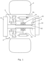
- FIG 1 schematically shows a drive system in the form of an electric hub drive.
- the hub drive comprises an electric motor 1 for driving a wheel 2 and as can be seen schematically in Figure 1 , the majority of the hub drive may be housed in the hub 2a of the wheel 2.
- the motor 1 comprises a stator 1 a and a rotor 1 b which is mounted for rotation via bearings 1c about an output shaft 3.
- the output shaft 3 is arranged for rotatingly driving the wheel 2 via a gear reduction stage 31.
- a braking system 32 is provided for breaking rotation of the output shaft 3 and hence rotation of the wheel 2.
- the structure and operation of the gear reduction stage 31 and braking system 32 are not particularly pertinent to the present invention and detailed description thereof is omitted. Indeed in some implementations the gear reduction stage and braking system might be omitted.
- the hub drive system further comprises gearing apparatus 4 which in turn comprises a gearing assembly 5 and a shift arrangement 6 for acting on the gearing assembly 5 and changing between gears.
- the gearing assembly 5 includes the shaft 3 as a rotary output member.
- the gearing assembly 5 comprises a dog hub 51 which is mounted for axial movement relative to the output shaft 3 but with rotational movement between the dog hub 51 and shaft 3 resisted.
- this mounting is achieved via the provision of mutually engaging splines on the outer curved surface of the shaft 3 and in the bore of the dog hub 51.
- the gearing assembly 5 also comprises a gearing arrangement 52 which comprises a plurality of planetary gear stages.
- Each planetary gear stage comprises a sun gear 521a, 521b, 521c and planetary gears 522 carried on a respective planet carrier 523.
- a common fixed ring gear 524 is provided within which the planetary gears 522 can run.
- Each planet carrier 523 is borne on the sun gear 521b, 521c of the subsequent planetary gear stage.
- a first of the sun gears 521a in the series is carried by the motor rotor 1b so as to rotate therewith.
- Each of the planetary gear stages act as a reduction gear. These gear stages preferably use planet gears which are small in comparison with the sun gear to give a relatively low reduction ratio of say in the order of 2.7:1 per stage.
- gear stages of approximately 2.7:1 which therefore gives a mechanical ratio spread of approximately 7:1 and combined with a traction motor, this can give a range of approximately 20:1.
- This ratio spread is typical of that required for a high performance military vehicle, either a wheel driven vehicle with a hub drive or a tracked vehicle.
- a third planetary gear stage could be added to give an overall spread of approximately 50:1.
- Each sun gear 521a, 521b, 521c comprises a dog ring 53 which is arranged for cooperation with the dog hub 51 so as to act as a dog clutch.
- Each dog ring 53 correspondingly acts as an output of the gearing arrangement 52.
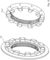
- Figures 3A and 3B show the dog hub 51 and one of the dog rings 53 in isolation. In Figure 3A these parts are shown separately from one another whereas in Figure 3B they are shown engaged with one another. Incidentally, in Figure 3B , the dog ring 53 is shown carrying planetary gears 522 whereas in Figure 3A there are no planetary gears. Thus this corresponds to the dog ring 53 carried by the first sun gear 521a which does not act as a planet carrier.
- the dog hub 51 carries a hub set of dog teeth 51a and the dog ring 53 carries a ring set of dog teeth 53a. These sets of teeth are radially extending and arranged to mutually engage with one another as shown in Figure 3B . That is to say the dog hub 51 is arranged to engage with the dog ring 53 when appropriately axially aligned with one another. Thus the dog hub 51 may be moved axially between positions where it engages with the dog ring 53 of the first sun gear 521a or the dog ring 53 of the second sun gear 521b or the dog ring 53 of the third sun gear 521c.
- the dog hub 51 may also be moved to intermediate positions where there is no engagement such that "neutral" positions can be adopted between gears. Furthermore the dog hub 51 may be moved between all of these positions by use of the shift arrangement 6 as will be described in more detail further below.
- the teeth in the hub set of teeth 51a are provided on a curved circumferential surface of the dog hub 51.
- Teeth in the ring set of teeth 53a are provided on a curved (inner) circumferential surface of the dog ring 53.
- Each tooth has a root at the respective curved surface and projects radially therefrom.
- the hub set of teeth 51a and ring sets of teeth 53a are arranged to allow rotational drive to be transferred from the respective sun gear 521a, 521b, 521c to the output shaft 3 via the dog hub 51 when there is appropriate alignment. Further the teeth 51a, 53a are arranged to allow engagement to be achieved by movement of the hub 51 axially into alignment with the respective dog ring 53 and to allow disengagement by axial movement away from that aligned position when not under rotational load.
- the sets of teeth 51a, 53a are arranged so that the set of hub teeth 51a may pass through the set of ring teeth 53a when there is appropriate register between the sets of teeth.
- the sets of teeth 51a, 53a are in register and thus disengagement of the teeth by movement of the hub 51 in either axial direction away from the engaging position is possible.
- the dog hub 51 may be moved from a first position in which it is engaged with the dog ring 53 of the second sun gear 521b to a first disengaged position which is axially to one side of its engaged position and to a second disengaged position which is axially to the other side of its first engaged position. Furthermore from the disengaged positons the dog hub 51 may be moved to second and third engaged positions, that is respectively into engagement with the dog ring 53 of the first sun gear 521a or the dog ring 53 of third sun gear 521c.
- a further planetary gear stage is provided then this may be engaged using the same mechanism. That is to say a fourth dog clutch arrangement may be provided with an appropriate dog ring carried on a fourth sun gear.
- the hub set of teeth 51a and the ring set of teeth 53a are profiled to help with operation of the system. First facing edges of the teeth which will contact with the respective other set of teeth during engagement are radiused to reduce contact stress and help to guide the teeth into engagement with one another. These radiused portions can be seen for example in Figures 4A and 4B .
- radiused surfaces 51b are provided at outer edges of the teeth and side walls of the teeth.
- radiused surfaces 53b are provided at the tips of the teeth, in troughs between the teeth and on sidewalls of the teeth.
- the respective sets of teeth 51a, 53a are profiled to encourage engagement and alignment of the teeth to be maintained when under rotational load when the respective dog clutch is transferring load.
- the mating surfaces of the teeth which transfer such load comprise complementary concave and convex portions which can rest in one another during rotational drive.
- the dog hub teeth 51a have a groove 51c provided in a side wall surface which is arranged to accept a corresponding convex portion 53c in the dog ring teeth 53a to help maintain alignment between the respective sets of teeth under rotational load.
- the convex portions 53c will tend to nestle into the concave groove portions 53c so resisting axial movement of the dog hub 51 out of engagement with the dog ring 53.
- the shift arrangement 6 comprises a shift fork 61 for accepting inputs from a user and at least one shift stick 62 for transmitting inputs from the shift fork 61 to the dog hub 51.
- the arrangement allows axial movement of the shift fork 61 to cause a corresponding axial movement of the dog hub 51.
- the shift fork 61 is provided on the opposite side of the motor 1.
- This again allows more flexibility in the arrangement of the system and for example allows the provision of the shift fork 61 to be on an inboard side of the motor whereas the gearing arrangement is on the outboard side of the motor.
- This can help from an overall system design point of view.
- this can help to lead to a more compact arrangement where, as can be seen for example by consideration of Figure 2 , part of the axial extent of the dog hub 51 may be accommodated at least partly within the axial extent of the motor rotor 1b. In the present case this is true at least when the dog hub 51 is in position which corresponds to it being retracted to its maximum extent towards the location of the motor 1.
- the shift arrangement 6 comprises a shift ring 63 to which are connected three shift sticks 62 with the remote end of the shift sticks 62 being connected to the dog hub 51.
- Each of the shift sticks 62 is located in a respective axial slot 33 provided in the outer curved surface of the shaft 3.
- These slots 33 and hence the shift sticks 62 may be equally spaced around the circumference of the shaft 3.
- the shift sticks 62 are spaced in this way and thus are spaced 120° from each other.
- the slots for the shift sticks may be machined into the outer curved surface of the shaft 3.
- the shift sticks 62 pass through the interior of the bearing 1c and hence through the rotor 1b.
- the shift ring 63 is arranged to be acted on via the shift fork 61 so the axial movement of the shift fork 61 will cause axial movement of the dog hub 51 via the shift ring 63 and the shift sticks 62.
- each dog hub may have its own respective associated set of shift sticks 62 and respective shift ring 63 for control by a respective shift fork.
- Figure 6 shows an alternative gearing apparatus which is similar to that shown in Figure 2 . Detailed description of most of Figure 6 is omitted for the sake of brevity with it being understood that those features not described are the same as those of the gearing apparatus shown in Figure 2 .
- the difference between the gearing arrangement shown in Figure 6 and that shown in Figure 2 is that an additional reduction gear stage 54 is provided between the motor rotor 1b and the remainder of the gearing arrangement 52.
- the output of this first reduction gear 54 acts as the input to the first sun gear 521a such that the highest gear available is via this reduction gear 54 and all the other gears are reduced.
- the reduction gear arrangement 31 of Figure 1 between the output shaft 3 and the wheel 2 to be driven might be omitted.
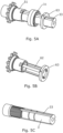
- FIG. 7 schematically shows yet another gearing apparatus. Again this is similar to that described above in relation to Figures 2 and a detailed description of those parts in common is omitted with it to be understood that those parts not described are the same as in the apparatus of Figure 2 .
- gearing assembly 5 is provided where different forms of dog clutch are provided but otherwise the gearing assembly is as described in relation to Figures 2 to 5 .
- the dog hub 51 carries separate sets of dog teeth 51a, 51a' and 51a". Further the sun gears of the gearing arrangement 52 carry different types of dog ring 53, 53' and 53".
- the first set of dog teeth 51a is arranged for engagement with the dog ring 53 carried by the second sun gear 521b.
- This set of dog teeth 51a and dog ring 53 are of the type described above and shown, for example in Figures 3A and 3B . That is to say the respective dog teeth 51a, 53a are radially extending and arranged so that when aligned and engaged, rotational drive may be transmitted via the sets of dog teeth 51a, 53a and also so that the teeth may be moved out of axial alignment with each other in either direction away from the aligned position.
- the second and third sets of dog teeth 51a', 51a" provided on the dog hub 51 are of the more conventional axial extending type and are arranged for mutual engagement with corresponding axial sets of teeth 53', 53" provided on the first sun gear 521a and the third sun gear 521c.
- these sets of teeth extend from axial faces on the dog hub 51, and sun gears 521a, 521c.
- Figure 8 shows the type of dog teeth arrangements which may be used for these dog clutches.
- first dog clutch 53, 51a is one of the type where the two sets of dog teeth may pass through one another
- second 53', 51a' and third 53", 51a" dog clutches are ones where engagement is provided by axial movement in a first direction and disengagement can only be achieved by axial movement in the reverse direction.
- engagement of the second set of hub teeth 51a' with the corresponding dog ring 53' may be achieved with the dog hub 51 at one axial extent of its movement whilst engagement of the third set of hub teeth 51a" may be achieved with the corresponding dog ring 53" with the hub 51 at its opposite axial extent of travel.
- engagement of the first dog clutch via the first set of dog teeth 51a and the appropriate dog ring 53 may be provided at an intermediate axial position of the dog hub 51.
- the arrangement shown in Figure 7 might be advantageous in some circumstances in that whilst the first dog clutch 53, 51a provides the capability of having more than two gears with the provision of a single axially moveable dog hub, the use of the more conventional dog clutches 53', 51a'; 53", 51a" at either end of the dog hub 51 can facilitate the provision of different torque transfer capabilities of the dog clutches and/or the provision of different diameters of dog clutch which may be useful, bearing in mind available space requirements.
- a larger diameter dog clutch may be used where greater torque transfer capabilities are required and/or where greater internal space within the dog clutch might be useful.
- a smaller diameter dog clutch might be used where lower torque transfer capabilities are required and/or where space outside of the dog clutch might be useful/required for some other purpose.
Landscapes
- Engineering & Computer Science (AREA)
- General Engineering & Computer Science (AREA)
- Mechanical Engineering (AREA)
- Chemical & Material Sciences (AREA)
- Combustion & Propulsion (AREA)
- Transportation (AREA)
- Mechanical Operated Clutches (AREA)
- Auxiliary Devices For And Details Of Packaging Control (AREA)
- Structure Of Transmissions (AREA)
Applications Claiming Priority (3)
| Application Number | Priority Date | Filing Date | Title |
|---|---|---|---|
| GBGB1800890.4A GB201800890D0 (en) | 2018-01-19 | 2018-01-19 | Gearing assemblies and apparatus |
| PCT/EP2019/051013 WO2019141710A1 (fr) | 2018-01-19 | 2019-01-16 | Ensembles d'engrenages et appareil |
| EP19700914.5A EP3740701B1 (fr) | 2018-01-19 | 2019-01-16 | Boite de vitesses et ensemble |
Related Parent Applications (1)
| Application Number | Title | Priority Date | Filing Date |
|---|---|---|---|
| EP19700914.5A Division EP3740701B1 (fr) | 2018-01-19 | 2019-01-16 | Boite de vitesses et ensemble |
Publications (2)
| Publication Number | Publication Date |
|---|---|
| EP4160047A2 true EP4160047A2 (fr) | 2023-04-05 |
| EP4160047A3 EP4160047A3 (fr) | 2023-06-28 |
Family
ID=61283674
Family Applications (2)
| Application Number | Title | Priority Date | Filing Date |
|---|---|---|---|
| EP19700914.5A Active EP3740701B1 (fr) | 2018-01-19 | 2019-01-16 | Boite de vitesses et ensemble |
| EP22209358.5A Pending EP4160047A3 (fr) | 2018-01-19 | 2019-01-16 | Ensembles d'engrenages et appareil |
Family Applications Before (1)
| Application Number | Title | Priority Date | Filing Date |
|---|---|---|---|
| EP19700914.5A Active EP3740701B1 (fr) | 2018-01-19 | 2019-01-16 | Boite de vitesses et ensemble |
Country Status (9)
| Country | Link |
|---|---|
| US (1) | US11255430B2 (fr) |
| EP (2) | EP3740701B1 (fr) |
| AU (1) | AU2019209386B2 (fr) |
| CA (1) | CA3088055A1 (fr) |
| ES (1) | ES2935463T3 (fr) |
| FI (1) | FI3740701T3 (fr) |
| GB (1) | GB201800890D0 (fr) |
| IL (1) | IL275848B2 (fr) |
| WO (1) | WO2019141710A1 (fr) |
Families Citing this family (4)
| Publication number | Priority date | Publication date | Assignee | Title |
|---|---|---|---|---|
| US20220266678A1 (en) * | 2015-03-17 | 2022-08-25 | Qinetiq Limited | Electric hub drive with braking assembly |
| IT201900020144A1 (it) * | 2019-10-31 | 2021-05-01 | Engines Eng S R L | Motoruota con cambio epicicloidale. |
| IT202200009842A1 (it) * | 2022-05-12 | 2023-11-12 | Iveco Spa | Mozzo ruota per assale di veicolo comprendente un sistema di riduzione integrato migliorato |
| US11859718B1 (en) * | 2023-04-24 | 2024-01-02 | Arvinmeritor Technology, Llc | Axle assembly having a shift collar |
Citations (1)
| Publication number | Priority date | Publication date | Assignee | Title |
|---|---|---|---|---|
| WO2016146628A1 (fr) | 2015-03-17 | 2016-09-22 | Qinetiq Limited | Ensemble d'engrenage, transmission de véhicule et moyeu de roue électrique associé |
Family Cites Families (14)
| Publication number | Priority date | Publication date | Assignee | Title |
|---|---|---|---|---|
| US1947033A (en) * | 1932-01-09 | 1934-02-13 | Bush Mfg Company | Clutch and transmission mechanism |
| GB697911A (en) * | 1949-07-28 | 1953-09-30 | Pol Ravigneaux | Improvements in or relating to epicyclic change-speed gears |
| DE965377C (de) * | 1955-02-26 | 1957-06-06 | Zahnradfabrik Friedrichshafen | Mehrgaengiges Zahnraederwechselgetriebe, insbesondere fuer Schlepper |
| US3386302A (en) * | 1966-05-02 | 1968-06-04 | Ford Motor Co | Multiple speed ratio, synchronized torque transmission mechanism |
| US3600962A (en) * | 1969-10-13 | 1971-08-24 | Ford Motor Co | Multiple ratio, manually controlled power transmission mechanism with self energizing neutral clutch |
| US4791825A (en) * | 1982-07-06 | 1988-12-20 | Tecumseh Products Company | Transaxle |
| JPH0284110A (ja) * | 1988-09-19 | 1990-03-26 | Iseki & Co Ltd | コンバイン等の変速操作装置 |
| DE10231609A1 (de) * | 2002-07-12 | 2004-01-29 | Zf Friedrichshafen Ag | Getriebeschaltung |
| JP4542809B2 (ja) * | 2004-04-23 | 2010-09-15 | 株式会社イケヤフォ−ミュラ | トルク断続装置 |
| DE102009023437A1 (de) * | 2009-05-29 | 2010-12-09 | Daimler Ag | Getriebevorrichtung |
| GB2480891B (en) | 2010-09-01 | 2017-05-24 | Wilkinson Nigel | Gear mechanism |
| KR101249813B1 (ko) | 2012-08-31 | 2013-04-02 | 한은수 | 기어 이동 어셈블리 및 그를 구비하는 변속기 |
| GB2506199A (en) * | 2012-09-25 | 2014-03-26 | Qinetiq Ltd | Drive member selection mechanism having torque transmitting projections on each face |
| DE102015219106A1 (de) * | 2015-10-02 | 2017-04-06 | Bayerische Motoren Werke Aktiengesellschaft | Vorrichtung zum axialen Verstellen eines Schaltelementes |
-
2018
- 2018-01-19 GB GBGB1800890.4A patent/GB201800890D0/en not_active Ceased
-
2019
- 2019-01-16 EP EP19700914.5A patent/EP3740701B1/fr active Active
- 2019-01-16 AU AU2019209386A patent/AU2019209386B2/en active Active
- 2019-01-16 EP EP22209358.5A patent/EP4160047A3/fr active Pending
- 2019-01-16 IL IL275848A patent/IL275848B2/en unknown
- 2019-01-16 WO PCT/EP2019/051013 patent/WO2019141710A1/fr unknown
- 2019-01-16 US US16/963,104 patent/US11255430B2/en active Active
- 2019-01-16 FI FIEP19700914.5T patent/FI3740701T3/fi active
- 2019-01-16 CA CA3088055A patent/CA3088055A1/fr active Pending
- 2019-01-16 ES ES19700914T patent/ES2935463T3/es active Active
Patent Citations (1)
| Publication number | Priority date | Publication date | Assignee | Title |
|---|---|---|---|---|
| WO2016146628A1 (fr) | 2015-03-17 | 2016-09-22 | Qinetiq Limited | Ensemble d'engrenage, transmission de véhicule et moyeu de roue électrique associé |
Also Published As
| Publication number | Publication date |
|---|---|
| US20210071758A1 (en) | 2021-03-11 |
| EP4160047A3 (fr) | 2023-06-28 |
| AU2019209386B2 (en) | 2024-10-17 |
| WO2019141710A1 (fr) | 2019-07-25 |
| ES2935463T3 (es) | 2023-03-07 |
| FI3740701T3 (fi) | 2023-01-13 |
| AU2019209386A1 (en) | 2020-07-16 |
| GB201800890D0 (en) | 2018-03-07 |
| EP3740701A1 (fr) | 2020-11-25 |
| EP3740701B1 (fr) | 2022-12-14 |
| CA3088055A1 (fr) | 2019-07-25 |
| IL275848B1 (en) | 2024-09-01 |
| IL275848B2 (en) | 2025-01-01 |
| US11255430B2 (en) | 2022-02-22 |
| IL275848A (en) | 2020-08-31 |
Similar Documents
| Publication | Publication Date | Title |
|---|---|---|
| US9920818B2 (en) | Gearboxes with compound planet gears and methods of operating thereof | |
| CN108136889B (zh) | Cvt差速器 | |
| AU2019209386B2 (en) | Gearing assemblies and apparatus | |
| EP3271202B1 (fr) | Ensemble d'engrenage, transmission de véhicule et moyeu de roue électrique associé | |
| JPS627419B2 (fr) | ||
| EP4067703A1 (fr) | Ensemble essieu et mécanisme de changement de vitesse pour un collier de changement de vitesse | |
| EP4102103A1 (fr) | Ensemble essieu à plusieurs vitesses ayant un embrayage unidirectionnel à roue libre | |
| EP3284971B1 (fr) | Système d'entraînement à deux vitesses à arbre unique | |
| EP3401563B1 (fr) | Plateau oscillant de contrôle de jeu à arbre unique, dispositif et système d'entraînement à deux vitesses avec embrayage à friction qui lui est appliquée | |
| US20190047398A1 (en) | Drive unit for vehicle | |
| CN115052772A (zh) | 用于机动车的电驱动装置 | |
| CN108688464B (zh) | 混合分动箱 | |
| US11634022B2 (en) | Power transmission unit | |
| CN114222677A (zh) | 带双离合器的两档变速电桥驱动系统 | |
| WO2009019430A1 (fr) | Boîte de changement de vitesse, intégrée, à plusieurs puissances | |
| CN213744741U (zh) | 变速箱和车辆 | |
| SE513133C2 (sv) | Fordonsväxellåda med sex framåtväxlar | |
| WO2024166899A1 (fr) | Transmission de véhicule | |
| CN115111323A (zh) | 变速器和驱动系统及车辆 | |
| CN110949105A (zh) | 两挡变速的电桥驱动系统和车辆 | |
| KR19990027695U (ko) | 자동 변속기의 드럼식 구조 |
Legal Events
| Date | Code | Title | Description |
|---|---|---|---|
| PUAI | Public reference made under article 153(3) epc to a published international application that has entered the european phase |
Free format text: ORIGINAL CODE: 0009012 |
|
| STAA | Information on the status of an ep patent application or granted ep patent |
Free format text: STATUS: THE APPLICATION HAS BEEN PUBLISHED |
|
| AC | Divisional application: reference to earlier application |
Ref document number: 3740701 Country of ref document: EP Kind code of ref document: P |
|
| AK | Designated contracting states |
Kind code of ref document: A2 Designated state(s): AL AT BE BG CH CY CZ DE DK EE ES FI FR GB GR HR HU IE IS IT LI LT LU LV MC MK MT NL NO PL PT RO RS SE SI SK SM TR |
|
| PUAL | Search report despatched |
Free format text: ORIGINAL CODE: 0009013 |
|
| P01 | Opt-out of the competence of the unified patent court (upc) registered |
Effective date: 20230504 |
|
| AK | Designated contracting states |
Kind code of ref document: A3 Designated state(s): AL AT BE BG CH CY CZ DE DK EE ES FI FR GB GR HR HU IE IS IT LI LT LU LV MC MK MT NL NO PL PT RO RS SE SI SK SM TR |
|
| RIC1 | Information provided on ipc code assigned before grant |
Ipc: F16D 11/00 20060101ALI20230524BHEP Ipc: B60K 17/04 20060101ALI20230524BHEP Ipc: F16H 3/083 20060101ALI20230524BHEP Ipc: F16D 11/14 20060101ALI20230524BHEP Ipc: F16D 11/10 20060101ALI20230524BHEP Ipc: F16D 11/08 20060101ALI20230524BHEP Ipc: F16D 21/04 20060101ALI20230524BHEP Ipc: B60K 17/02 20060101ALI20230524BHEP Ipc: B60K 7/00 20060101ALI20230524BHEP Ipc: F16H 3/70 20060101ALI20230524BHEP Ipc: F16H 3/66 20060101ALI20230524BHEP Ipc: F16H 3/24 20060101AFI20230524BHEP |
|
| STAA | Information on the status of an ep patent application or granted ep patent |
Free format text: STATUS: REQUEST FOR EXAMINATION WAS MADE |
|
| 17P | Request for examination filed |
Effective date: 20231221 |
|
| RBV | Designated contracting states (corrected) |
Designated state(s): AL AT BE BG CH CY CZ DE DK EE ES FI FR GB GR HR HU IE IS IT LI LT LU LV MC MK MT NL NO PL PT RO RS SE SI SK SM TR |