EP3284971B1 - Système d'entraînement à deux vitesses à arbre unique - Google Patents
Système d'entraînement à deux vitesses à arbre unique Download PDFInfo
- Publication number
- EP3284971B1 EP3284971B1 EP16202293.3A EP16202293A EP3284971B1 EP 3284971 B1 EP3284971 B1 EP 3284971B1 EP 16202293 A EP16202293 A EP 16202293A EP 3284971 B1 EP3284971 B1 EP 3284971B1
- Authority
- EP
- European Patent Office
- Prior art keywords
- gear
- circumferential surface
- cone
- sun gear
- synchronizer
- Prior art date
- Legal status (The legal status is an assumption and is not a legal conclusion. Google has not performed a legal analysis and makes no representation as to the accuracy of the status listed.)
- Active
Links
- 230000009467 reduction Effects 0.000 claims description 42
- 230000004044 response Effects 0.000 claims description 3
- 230000005540 biological transmission Effects 0.000 description 8
- 230000007246 mechanism Effects 0.000 description 5
- 230000009471 action Effects 0.000 description 4
- 230000006870 function Effects 0.000 description 4
- 230000008901 benefit Effects 0.000 description 3
- 230000003247 decreasing effect Effects 0.000 description 3
- 230000004075 alteration Effects 0.000 description 2
- 230000008859 change Effects 0.000 description 2
- 238000005516 engineering process Methods 0.000 description 2
- 239000000446 fuel Substances 0.000 description 2
- 238000009434 installation Methods 0.000 description 2
- 230000004048 modification Effects 0.000 description 2
- 238000012986 modification Methods 0.000 description 2
- 230000008878 coupling Effects 0.000 description 1
- 238000010168 coupling process Methods 0.000 description 1
- 238000005859 coupling reaction Methods 0.000 description 1
- 230000000694 effects Effects 0.000 description 1
- 239000002783 friction material Substances 0.000 description 1
Images


Classifications
-
- F—MECHANICAL ENGINEERING; LIGHTING; HEATING; WEAPONS; BLASTING
- F16—ENGINEERING ELEMENTS AND UNITS; GENERAL MEASURES FOR PRODUCING AND MAINTAINING EFFECTIVE FUNCTIONING OF MACHINES OR INSTALLATIONS; THERMAL INSULATION IN GENERAL
- F16H—GEARING
- F16H3/00—Toothed gearings for conveying rotary motion with variable gear ratio or for reversing rotary motion
- F16H3/44—Toothed gearings for conveying rotary motion with variable gear ratio or for reversing rotary motion using gears having orbital motion
-
- H—ELECTRICITY
- H02—GENERATION; CONVERSION OR DISTRIBUTION OF ELECTRIC POWER
- H02K—DYNAMO-ELECTRIC MACHINES
- H02K7/00—Arrangements for handling mechanical energy structurally associated with dynamo-electric machines, e.g. structural association with mechanical driving motors or auxiliary dynamo-electric machines
- H02K7/10—Structural association with clutches, brakes, gears, pulleys or mechanical starters
- H02K7/116—Structural association with clutches, brakes, gears, pulleys or mechanical starters with gears
-
- F—MECHANICAL ENGINEERING; LIGHTING; HEATING; WEAPONS; BLASTING
- F16—ENGINEERING ELEMENTS AND UNITS; GENERAL MEASURES FOR PRODUCING AND MAINTAINING EFFECTIVE FUNCTIONING OF MACHINES OR INSTALLATIONS; THERMAL INSULATION IN GENERAL
- F16H—GEARING
- F16H37/00—Combinations of mechanical gearings, not provided for in groups F16H1/00 - F16H35/00
- F16H37/02—Combinations of mechanical gearings, not provided for in groups F16H1/00 - F16H35/00 comprising essentially only toothed or friction gearings
- F16H37/06—Combinations of mechanical gearings, not provided for in groups F16H1/00 - F16H35/00 comprising essentially only toothed or friction gearings with a plurality of driving or driven shafts; with arrangements for dividing torque between two or more intermediate shafts
- F16H37/08—Combinations of mechanical gearings, not provided for in groups F16H1/00 - F16H35/00 comprising essentially only toothed or friction gearings with a plurality of driving or driven shafts; with arrangements for dividing torque between two or more intermediate shafts with differential gearing
- F16H37/0806—Combinations of mechanical gearings, not provided for in groups F16H1/00 - F16H35/00 comprising essentially only toothed or friction gearings with a plurality of driving or driven shafts; with arrangements for dividing torque between two or more intermediate shafts with differential gearing with a plurality of driving or driven shafts
- F16H37/0813—Combinations of mechanical gearings, not provided for in groups F16H1/00 - F16H35/00 comprising essentially only toothed or friction gearings with a plurality of driving or driven shafts; with arrangements for dividing torque between two or more intermediate shafts with differential gearing with a plurality of driving or driven shafts with only one input shaft
-
- B—PERFORMING OPERATIONS; TRANSPORTING
- B60—VEHICLES IN GENERAL
- B60K—ARRANGEMENT OR MOUNTING OF PROPULSION UNITS OR OF TRANSMISSIONS IN VEHICLES; ARRANGEMENT OR MOUNTING OF PLURAL DIVERSE PRIME-MOVERS IN VEHICLES; AUXILIARY DRIVES FOR VEHICLES; INSTRUMENTATION OR DASHBOARDS FOR VEHICLES; ARRANGEMENTS IN CONNECTION WITH COOLING, AIR INTAKE, GAS EXHAUST OR FUEL SUPPLY OF PROPULSION UNITS IN VEHICLES
- B60K1/00—Arrangement or mounting of electrical propulsion units
-
- B—PERFORMING OPERATIONS; TRANSPORTING
- B60—VEHICLES IN GENERAL
- B60L—PROPULSION OF ELECTRICALLY-PROPELLED VEHICLES; SUPPLYING ELECTRIC POWER FOR AUXILIARY EQUIPMENT OF ELECTRICALLY-PROPELLED VEHICLES; ELECTRODYNAMIC BRAKE SYSTEMS FOR VEHICLES IN GENERAL; MAGNETIC SUSPENSION OR LEVITATION FOR VEHICLES; MONITORING OPERATING VARIABLES OF ELECTRICALLY-PROPELLED VEHICLES; ELECTRIC SAFETY DEVICES FOR ELECTRICALLY-PROPELLED VEHICLES
- B60L15/00—Methods, circuits, or devices for controlling the traction-motor speed of electrically-propelled vehicles
- B60L15/20—Methods, circuits, or devices for controlling the traction-motor speed of electrically-propelled vehicles for control of the vehicle or its driving motor to achieve a desired performance, e.g. speed, torque, programmed variation of speed
- B60L15/2036—Electric differentials, e.g. for supporting steering vehicles
-
- F—MECHANICAL ENGINEERING; LIGHTING; HEATING; WEAPONS; BLASTING
- F16—ENGINEERING ELEMENTS AND UNITS; GENERAL MEASURES FOR PRODUCING AND MAINTAINING EFFECTIVE FUNCTIONING OF MACHINES OR INSTALLATIONS; THERMAL INSULATION IN GENERAL
- F16D—COUPLINGS FOR TRANSMITTING ROTATION; CLUTCHES; BRAKES
- F16D23/00—Details of mechanically-actuated clutches not specific for one distinct type
- F16D23/02—Arrangements for synchronisation, also for power-operated clutches
- F16D23/04—Arrangements for synchronisation, also for power-operated clutches with an additional friction clutch
-
- F—MECHANICAL ENGINEERING; LIGHTING; HEATING; WEAPONS; BLASTING
- F16—ENGINEERING ELEMENTS AND UNITS; GENERAL MEASURES FOR PRODUCING AND MAINTAINING EFFECTIVE FUNCTIONING OF MACHINES OR INSTALLATIONS; THERMAL INSULATION IN GENERAL
- F16H—GEARING
- F16H3/00—Toothed gearings for conveying rotary motion with variable gear ratio or for reversing rotary motion
- F16H3/44—Toothed gearings for conveying rotary motion with variable gear ratio or for reversing rotary motion using gears having orbital motion
- F16H3/46—Gearings having only two central gears, connected by orbital gears
-
- F—MECHANICAL ENGINEERING; LIGHTING; HEATING; WEAPONS; BLASTING
- F16—ENGINEERING ELEMENTS AND UNITS; GENERAL MEASURES FOR PRODUCING AND MAINTAINING EFFECTIVE FUNCTIONING OF MACHINES OR INSTALLATIONS; THERMAL INSULATION IN GENERAL
- F16H—GEARING
- F16H3/00—Toothed gearings for conveying rotary motion with variable gear ratio or for reversing rotary motion
- F16H3/44—Toothed gearings for conveying rotary motion with variable gear ratio or for reversing rotary motion using gears having orbital motion
- F16H3/62—Gearings having three or more central gears
- F16H3/66—Gearings having three or more central gears composed of a number of gear trains without drive passing from one train to another
-
- B—PERFORMING OPERATIONS; TRANSPORTING
- B60—VEHICLES IN GENERAL
- B60K—ARRANGEMENT OR MOUNTING OF PROPULSION UNITS OR OF TRANSMISSIONS IN VEHICLES; ARRANGEMENT OR MOUNTING OF PLURAL DIVERSE PRIME-MOVERS IN VEHICLES; AUXILIARY DRIVES FOR VEHICLES; INSTRUMENTATION OR DASHBOARDS FOR VEHICLES; ARRANGEMENTS IN CONNECTION WITH COOLING, AIR INTAKE, GAS EXHAUST OR FUEL SUPPLY OF PROPULSION UNITS IN VEHICLES
- B60K17/00—Arrangement or mounting of transmissions in vehicles
- B60K17/04—Arrangement or mounting of transmissions in vehicles characterised by arrangement, location, or kind of gearing
- B60K17/06—Arrangement or mounting of transmissions in vehicles characterised by arrangement, location, or kind of gearing of change-speed gearing
- B60K17/08—Arrangement or mounting of transmissions in vehicles characterised by arrangement, location, or kind of gearing of change-speed gearing of mechanical type
-
- B—PERFORMING OPERATIONS; TRANSPORTING
- B60—VEHICLES IN GENERAL
- B60K—ARRANGEMENT OR MOUNTING OF PROPULSION UNITS OR OF TRANSMISSIONS IN VEHICLES; ARRANGEMENT OR MOUNTING OF PLURAL DIVERSE PRIME-MOVERS IN VEHICLES; AUXILIARY DRIVES FOR VEHICLES; INSTRUMENTATION OR DASHBOARDS FOR VEHICLES; ARRANGEMENTS IN CONNECTION WITH COOLING, AIR INTAKE, GAS EXHAUST OR FUEL SUPPLY OF PROPULSION UNITS IN VEHICLES
- B60K17/00—Arrangement or mounting of transmissions in vehicles
- B60K17/04—Arrangement or mounting of transmissions in vehicles characterised by arrangement, location, or kind of gearing
- B60K17/16—Arrangement or mounting of transmissions in vehicles characterised by arrangement, location, or kind of gearing of differential gearing
-
- B—PERFORMING OPERATIONS; TRANSPORTING
- B60—VEHICLES IN GENERAL
- B60K—ARRANGEMENT OR MOUNTING OF PROPULSION UNITS OR OF TRANSMISSIONS IN VEHICLES; ARRANGEMENT OR MOUNTING OF PLURAL DIVERSE PRIME-MOVERS IN VEHICLES; AUXILIARY DRIVES FOR VEHICLES; INSTRUMENTATION OR DASHBOARDS FOR VEHICLES; ARRANGEMENTS IN CONNECTION WITH COOLING, AIR INTAKE, GAS EXHAUST OR FUEL SUPPLY OF PROPULSION UNITS IN VEHICLES
- B60K1/00—Arrangement or mounting of electrical propulsion units
- B60K2001/001—Arrangement or mounting of electrical propulsion units one motor mounted on a propulsion axle for rotating right and left wheels of this axle
-
- F—MECHANICAL ENGINEERING; LIGHTING; HEATING; WEAPONS; BLASTING
- F16—ENGINEERING ELEMENTS AND UNITS; GENERAL MEASURES FOR PRODUCING AND MAINTAINING EFFECTIVE FUNCTIONING OF MACHINES OR INSTALLATIONS; THERMAL INSULATION IN GENERAL
- F16H—GEARING
- F16H2200/00—Transmissions for multiple ratios
- F16H2200/0021—Transmissions for multiple ratios specially adapted for electric vehicles
-
- F—MECHANICAL ENGINEERING; LIGHTING; HEATING; WEAPONS; BLASTING
- F16—ENGINEERING ELEMENTS AND UNITS; GENERAL MEASURES FOR PRODUCING AND MAINTAINING EFFECTIVE FUNCTIONING OF MACHINES OR INSTALLATIONS; THERMAL INSULATION IN GENERAL
- F16H—GEARING
- F16H2200/00—Transmissions for multiple ratios
- F16H2200/003—Transmissions for multiple ratios characterised by the number of forward speeds
- F16H2200/0034—Transmissions for multiple ratios characterised by the number of forward speeds the gear ratios comprising two forward speeds
-
- F—MECHANICAL ENGINEERING; LIGHTING; HEATING; WEAPONS; BLASTING
- F16—ENGINEERING ELEMENTS AND UNITS; GENERAL MEASURES FOR PRODUCING AND MAINTAINING EFFECTIVE FUNCTIONING OF MACHINES OR INSTALLATIONS; THERMAL INSULATION IN GENERAL
- F16H—GEARING
- F16H2200/00—Transmissions for multiple ratios
- F16H2200/20—Transmissions using gears with orbital motion
- F16H2200/2002—Transmissions using gears with orbital motion characterised by the number of sets of orbital gears
- F16H2200/2005—Transmissions using gears with orbital motion characterised by the number of sets of orbital gears with one sets of orbital gears
-
- F—MECHANICAL ENGINEERING; LIGHTING; HEATING; WEAPONS; BLASTING
- F16—ENGINEERING ELEMENTS AND UNITS; GENERAL MEASURES FOR PRODUCING AND MAINTAINING EFFECTIVE FUNCTIONING OF MACHINES OR INSTALLATIONS; THERMAL INSULATION IN GENERAL
- F16H—GEARING
- F16H2200/00—Transmissions for multiple ratios
- F16H2200/20—Transmissions using gears with orbital motion
- F16H2200/2002—Transmissions using gears with orbital motion characterised by the number of sets of orbital gears
- F16H2200/2007—Transmissions using gears with orbital motion characterised by the number of sets of orbital gears with two sets of orbital gears
-
- F—MECHANICAL ENGINEERING; LIGHTING; HEATING; WEAPONS; BLASTING
- F16—ENGINEERING ELEMENTS AND UNITS; GENERAL MEASURES FOR PRODUCING AND MAINTAINING EFFECTIVE FUNCTIONING OF MACHINES OR INSTALLATIONS; THERMAL INSULATION IN GENERAL
- F16H—GEARING
- F16H2200/00—Transmissions for multiple ratios
- F16H2200/20—Transmissions using gears with orbital motion
- F16H2200/203—Transmissions using gears with orbital motion characterised by the engaging friction means not of the freewheel type, e.g. friction clutches or brakes
- F16H2200/2033—Transmissions using gears with orbital motion characterised by the engaging friction means not of the freewheel type, e.g. friction clutches or brakes with one engaging means
-
- F—MECHANICAL ENGINEERING; LIGHTING; HEATING; WEAPONS; BLASTING
- F16—ENGINEERING ELEMENTS AND UNITS; GENERAL MEASURES FOR PRODUCING AND MAINTAINING EFFECTIVE FUNCTIONING OF MACHINES OR INSTALLATIONS; THERMAL INSULATION IN GENERAL
- F16H—GEARING
- F16H2200/00—Transmissions for multiple ratios
- F16H2200/20—Transmissions using gears with orbital motion
- F16H2200/203—Transmissions using gears with orbital motion characterised by the engaging friction means not of the freewheel type, e.g. friction clutches or brakes
- F16H2200/2035—Transmissions using gears with orbital motion characterised by the engaging friction means not of the freewheel type, e.g. friction clutches or brakes with two engaging means
-
- F—MECHANICAL ENGINEERING; LIGHTING; HEATING; WEAPONS; BLASTING
- F16—ENGINEERING ELEMENTS AND UNITS; GENERAL MEASURES FOR PRODUCING AND MAINTAINING EFFECTIVE FUNCTIONING OF MACHINES OR INSTALLATIONS; THERMAL INSULATION IN GENERAL
- F16H—GEARING
- F16H3/00—Toothed gearings for conveying rotary motion with variable gear ratio or for reversing rotary motion
- F16H3/44—Toothed gearings for conveying rotary motion with variable gear ratio or for reversing rotary motion using gears having orbital motion
- F16H3/46—Gearings having only two central gears, connected by orbital gears
- F16H3/48—Gearings having only two central gears, connected by orbital gears with single orbital gears or pairs of rigidly-connected orbital gears
- F16H3/52—Gearings having only two central gears, connected by orbital gears with single orbital gears or pairs of rigidly-connected orbital gears comprising orbital spur gears
- F16H3/54—Gearings having only two central gears, connected by orbital gears with single orbital gears or pairs of rigidly-connected orbital gears comprising orbital spur gears one of the central gears being internally toothed and the other externally toothed
-
- F—MECHANICAL ENGINEERING; LIGHTING; HEATING; WEAPONS; BLASTING
- F16—ENGINEERING ELEMENTS AND UNITS; GENERAL MEASURES FOR PRODUCING AND MAINTAINING EFFECTIVE FUNCTIONING OF MACHINES OR INSTALLATIONS; THERMAL INSULATION IN GENERAL
- F16H—GEARING
- F16H3/00—Toothed gearings for conveying rotary motion with variable gear ratio or for reversing rotary motion
- F16H3/44—Toothed gearings for conveying rotary motion with variable gear ratio or for reversing rotary motion using gears having orbital motion
- F16H3/78—Special adaptation of synchronisation mechanisms to these gearings
-
- Y—GENERAL TAGGING OF NEW TECHNOLOGICAL DEVELOPMENTS; GENERAL TAGGING OF CROSS-SECTIONAL TECHNOLOGIES SPANNING OVER SEVERAL SECTIONS OF THE IPC; TECHNICAL SUBJECTS COVERED BY FORMER USPC CROSS-REFERENCE ART COLLECTIONS [XRACs] AND DIGESTS
- Y02—TECHNOLOGIES OR APPLICATIONS FOR MITIGATION OR ADAPTATION AGAINST CLIMATE CHANGE
- Y02T—CLIMATE CHANGE MITIGATION TECHNOLOGIES RELATED TO TRANSPORTATION
- Y02T10/00—Road transport of goods or passengers
- Y02T10/60—Other road transportation technologies with climate change mitigation effect
- Y02T10/72—Electric energy management in electromobility
Definitions
- the present invention relates generally to a single-shaft two-speed drive system for an electric vehicle, and more particularly to the field of application of a technology for implementing gear reduction ratios based on the gear reduction and direct coupling of planetary gears to an electric vehicle and similar drive systems.
- Conventional drive units for an electric vehicle are composed of a housing configured to surround a motor, a gear box, and a differential configured to receive the driving power of the gear box.
- the gear box and the differential are disposed on separate shafts.
- the power transmission path of a drive unit for an electric vehicle is composed of two shafts.
- a motor composed of a rotor and a stator is disposed inside a housing, one end of a first shaft is coupled to be operated in conjunction with the rotor, the other end of the first shaft is coupled to be operated in conjunction with a differential on the same axial line, and the differential is coupled to a gear box having a second shaft of a different phase difference.
- the drive device of this patent is disadvantageous in that a space in which a gear box is installed is limited and overall volume and weight are increased because the drive device of this patent has a structure in which the gear box is required to be disposed outside the housing. Furthermore, the conventional drive units are problematic in that fuel efficiency is decreased because volume and weight are increased due to the structural characteristics of a connection structure that connects multiple shafts.
- the drive unit device of this patent at least one planetary gear set, a motor, and a differential are densely disposed along the same axial line within a single housing, so that a limitation related to an installation space can be reduced by decreasing the volume of the device, the number of parts and weight can be reduced, and noise and vibration can be reduced due to the characteristic in which the generation of power and gear reduction action are simultaneously performed on the single same axial line.
- the drive unit device of this patent is problematic in that a gear reduction ratio suitable for the inherent characteristic of the planetary gear set can only be passively obtained.
- the CN104827898A describes a two-gear speed changing power system of an electric automobile.
- the two-gear speed changing power system comprises a driving motor, a differential mechanism, a right half shaft and a left half shaft, and further comprises a planetary gear speed reducing mechanism, a synchronizer and two sets of wheel rim speed reducing mechanisms, wherein the planetary gear speed reducing mechanism and the synchronizer are located in a shell of the driving motor to form an integrated structure.
- CN103332108A describes a two-gear power transmission system for a BEV (Blade Electric Vehicle) integrated planetary gear train, which comprises a driving motor, a two-gear planetary gear train transmission, a gear shift mechanism with a synchronizer, a differential device, a left half shaft and a right half shaft, wherein the two-gear planetary gear train transmission is formed by the series connection of a first stage planetary gear train and a second stage planetary gear train the driving motor, the two-gear planetary gear train transmission and the differential device are integrated.
- BEV Battery Electric Vehicle
- the conventional drive systems obtain gear reduction by using a difference in rotation ratio in such a way as to enable a small gear to rotate a large gear on a shaft parallel to the shaft of the small gear in order to implement reduction.
- the present invention is intended to obtain two gear reduction ratios along the same axial line without a change in axis by means of a synchronizer and a planetary gear set by using the characteristics of planetary gears.
- an embodiment of the present invention provides a drive system that can implement two speeds by using a synchronizer and two single planetary gear sets.
- a single-shaft two-speed drive system configured to enable generation of power and gear reduction to be performed on a single drive shaft, the system including:
- a single-shaft two-speed drive system including a synchronizer according to the present invention is described.
- the terms used herein to refer to the components of the single-shaft two-speed drive system and the terms used herein to describe driving characteristics are intended for ease of description. Accordingly, the present invention is not limited by the terms used herein, and other terms that refer to objects having equivalent technical meanings may be used.
- FIG. 1 schematically shows the structure of a single-shaft two-speed drive system including two planetary gear sets and a synchronizer according to an embodiment of the present invention. This drawing is intended to allow the structure of the single-shaft two-speed drive system including two planetary gear sets and a synchronizer to be easily understood.
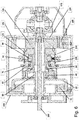
- FIG. 2 shows the structure of a single-shaft two-speed drive system including a single planetary gear set and a synchronizer, presented for purposes of explanation only.
- FIG. 3 is a sectional view of FIG. 2 .
- FIG. 4 shows the structure of a typical synchronizer. In FIGS. 1 to 3 , the illustration of the teeth of gears is omitted.
- the single-shaft two-speed drive system includes a housing 400, a motor unit 25, a first planetary gear set 200, a fastening cone 70, a synchronizer 115, an integrating cone 120, and a differential 170.
- the motor unit 25 includes a stator 10 and a rotor 20, and the first planetary gear set 200 includes a first sun gear 30, a plurality of first planetary gears 40, a first ring gear 60, and a first carrier 50.
- the synchronizer 115 includes a hub 80, a sleeve 90, a first synchronizer ring 100, and a second synchronizer ring 110.
- the motor unit 25 includes the stator 10 fastened onto the inner circumferential surface of the housing 400 by a fastening means, such as a bolt or the like, and configured such that a coil is wound around the outer circumferential surface thereof, and a rotor 20 disposed outside the stator 10 and configured to be rotated in response to the application of power to the coil.
- the motor unit 25 may include a rotor disposed inside a stator, unlike the motor unit 25 shown in FIG. 2 , or may include a motor unit commonly used. This feature may be applied to the example described with regard to FIG. 2 .
- the first planetary gear set 200 is configured to include: a first sun gear 30 configured to be rotated in conjunction with the rotor 20, and configured such that a plurality of gear teeth are formed on the outer circumferential surface thereof; a plurality of first planetary gears 40 configured to engage with the gear teeth of the first sun gear 30 and be operated in conjunction with the first sun gear 30; a first ring gear 60 configured such that an internal gear adapted to engage with the first planetary gears 40 is formed on the inner circumferential surface thereof; and a first carrier 50 configured to couple the plurality of first planetary gears 40 so that they are operated in conjunction with each other.
- the first planetary gears 40 are rotatably coupled to the first carrier 50, and the first carrier 50 is rotated by the constraining force of the first planetary gears 40.
- the fastening cone 70 is located on the outer circumferential surface of the first ring gear 60, and is fastened to the inner circumferential surface of the housing 400.
- the fastening cone 70 may have various shapes. These various shapes may be applied to the example described with regard to FIG. 2 .
- the integrating cone 120 is mounted on the outer circumferential surface of the first carrier 50.
- the integrating cone 120 may have various shapes. These various shapes may be applied to the example being described with regard to FIG. 2 .
- the synchronizer 115 is disposed between the fastening cone 70 and the integrating cone 120.
- the hub 80 of the synchronizer 115 is mounted on the outer circumferential surface of the first ring gear 60, and the sleeve 90 of the synchronizer 115 is coupled onto the outer circumferential surface of the hub 80 in a spline manner and laterally moved along the outer circumferential surface of the hub 80.
- the first and second synchronizer rings 100 and 110 of the synchronizer 115 are disposed on both surfaces of the sleeve 90.
- the first synchronizer ring 100 is located on one side surface of the fastening cone 70
- the second synchronizer ring 110 is located on one side surface of the integrating cone 120.
- the synchronizer 115 is a synchronizer having a typical structure including the hub 80, the sleeve 90, the first synchronizer ring 100, and the second synchronizer ring 110.
- the hub 80, sleeve 90, and first and second synchronizer rings 100 and 110 of the synchronizer 115 may have different shapes and structures. These different shapes and structures may be applied to the example described with regard to FIG. 2 .
- the first and second synchronizer rings 100 and 110 of the synchronizer 115 may have a structure, such as those shown in FIGS. 2 to 4 . Although not shown in FIGS.
- the first and second synchronizer rings 100 and 110 may have the structure of a commonly used synchronizer ring or the structures of synchronizer rings having various shapes.
- the first and second synchronizer rings 100 and 110 of the synchronizer 115 may have not only various shapes but also various structures in which the first synchronizer ring 100 and the second synchronizer ring 110 are coupled to each other.
- Each of the first synchronizer ring 100 and the second synchronizer ring 110 may be plural in number.
- the first and second synchronizer rings 100 and 110 generally function to forcibly hold and decelerate or accelerate counterpart gears, rotating at the different numbers of revolutions, by using strong frictional force, like a brake, because a friction material is attached onto the inner circumferential surface or outer circumferential surface of each of the synchronizer rings, thereby adjusting the numbers of revolutions of the two gears to the same value.
- the first synchronizer ring 100 is coupled to the fastening cone 70 and performs frictional action when the sleeve 90 moves in the direction of the fastening cone 70
- the second synchronizer ring 110 is coupled to the integrating cone 120 and performs frictional action when the sleeve 90 moves in the direction of the integrating cone 120.
- the differential 170 is located on the other side surface of the integrating cone 120, and is connected to be operated in conjunction with the first carrier 50.
- the differential 170 includes a differential that is commonly used in a drive system. Other differentials that perform a differential function are included in embodiments of the present invention. These differentials may be applied to the example being described with regard to FIG. 2 .
- the rotor 20 When power is applied to the coil, the rotor 20 is rotated.
- the rotor 20 engages with the first sun gear 30. Accordingly, when the rotor 20 is rotated, rotating power is transferred to the first sun gear 30, and thus rotates the first sun gear 30.
- the first sun gear 30 rotates the engaged first planetary gears 40.
- the first sun gear 30 and the first planetary gears 40 are rotated in opposite directions, and the first planetary gears 40 and the first carrier 50 are rotated in the same direction. Since the first planetary gears 40 engage with the first sun gear 30 on the inner sides thereof and engage with the internal gear of the first ring gear 60 on the outer sides thereof, they perform revolution and rotation.
- the first carrier 50 is connected to operate in conjunction with the differential 170.
- This example has a power transmission path in which the rotating power of the rotor 20 is transmitted to the differential 170 via the first planetary gear set 200.
- gear reduction ratio varies depending on the lateral movement of the sleeve 90 of the synchronizer 115. This gear reduction ratio will be described below.
- the single-shaft two-speed drive system is defined in that the sleeve 90 of the synchronizer 115 is moved in the direction of the fastening cone 70 and coupled to the fastening cone 70 to thus obtain a single gear reduction ratio and the sleeve 90 is moved in the direction of the integrating cone 120 and coupled to the integrating cone 120 to thus obtain driving power without gear reduction.
- the sleeve 90 is moved in the direction of the fastening cone 70.
- the first ring gear 60 is stopped.
- the driving of the first sun gear 30 becomes the output of the first carrier 50.
- the number of revolutions of the first carrier 50 is generally reduced at a ratio of 3 to 4:1 with respect to the number of revolutions of the first sun gear 30.
- Number of revolutions N C 1 of first carrier Number of teeth Z S 1 of first sun gear Number of teeth Z S 1 of first sun gear + Number of teeth Z R 1 of first ring gear ⁇ Number of revolutions N S 1 of first sun gear
- Equation 2 for example, when 30 and 60 are substituted for the number of teeth Z S 1 of the first sun gear and the number of teeth Z R 1 of the first ring gear, respectively, the number of revolutions N C 1 of the first carrier becomes 1/3 of the number of revolutions N S 1 of the first sun gear.
- the number of teeth Z S 1 of the first sun gear is made different from the number of teeth Z R 1 of the first ring gear, an appropriate gear reduction ratio can be formed.
- the number of revolutions N C 1 of the first carrier is reduced at a ratio 3 to 4:1 with respect to the number of revolutions N S 1 of the first sun gear.
- the first sun gear 30 and the first ring gear 60 are directly connected to each other and driven at a ratio of 1:1. That is, since the first sun gear 30 and the first ring gear 60 are coupled to each other and thus the speed of the motor is transferred to the differential without change, high-speed rotation is performed without gear reduction.
- gear reduction ratio is formed based on the number of teeth Z S 1 of the first sun gear is different from the number of teeth Z R 1 of the first ring gear when the sleeve 90 is moved in the direction of the fastening cone 70, and the first sun gear 30 and the first ring gear 60 are combined with each other and rotated without gear reduction when the sleeve 90 is moved in the direction of the integrating cone 120.
- a single-shaft two-speed drive system capable of enabling two speeds by using only a single planetary gear set, such as the embodiment of the present invention, may be constructed.
- the first embodiment of the present invention can reduce noise and vibration compared to an existing multi-axis drive system in which operating noise and vibration increase during high-speed rotation.
- FIG. 5 shows the structure of a single-shaft two-speed drive system including two planetary gear sets and a synchronizer according to an embodiment of the present invention.
- FIG. 6 is a plan sectional view of FIG. 5 . In FIGS. 5 and 6 , the illustration of the teeth of gears is omitted.
- the single-shaft two-speed drive system includes a housing 400, a motor unit 25, a first planetary gear set 200, a fastening cone 70, a synchronizer 115, an integrating cone 120, a second planetary gear set 300, and a differential 170.
- the embodiment of the present invention shown in FIG. 5 is the case where one more planetary gear set is added to the embodiment of the present invention shown in FIG. 2 .
- the embodiment of the present invention shown in FIG. 5 is directed to a single-shaft two-speed drive system in which a second planetary gear set 300 is additionally disposed on the same axial line between the integrating cone 120 and the differential 170 in FIG. 2 .
- the embodiment of the present invention shown in FIG. 5 includes all the motor unit 25, the first planetary gear set 200, the fastening cone 70, the synchronizer 115, the integrating cone 120 and the differential 170 described in conjunction with the embodiment of the present invention shown in FIG. 2 . Furthermore, in this embodiment, the second planetary gear set 300 is additionally disposed between the integrating cone 120 and the differential 170.
- the motor unit 25 includes a stator 10 and a rotor 20, the first planetary gear set 200 includes a first sun gear 30, a plurality of first planetary gears 40, a first ring gear 60 and a first carrier 50, and the synchronizer 115 includes a hub 80, a sleeve 90, a first synchronizer ring 100, and a second synchronizer ring 110.
- the second planetary gear set 300 includes a second sun gear 130, a plurality of second planetary gears 140, a second ring gear 160, and a second carrier 150.
- the motor unit 25 the first planetary gear set 200, the fastening cone 70, the synchronizer 115, the integrating cone 120, and the differential 170 are the same as those described in conjunction with the disclosure described with regard to FIG. 2 .
- the second planetary gear set 300 is configured to include: the second sun gear 130 located on the other side surface of the integrating cone 120, and configured to be rotated in conjunction with the first carrier 50 and have a plurality of gear teeth on the outer circumferential surface thereof; the plurality of second planetary gears 140 configured to engage with the gear teeth of the second sun gear 130 and be operated in conjunction with the second sun gear 130; the second ring gear 160 configured to have an internal gear, engaging with the second planetary gears 140, on the inner circumferential surface thereof, and fastened onto the inner circumferential surface of the housing 400; and the second carrier 150 connected such that the plurality of second planetary gears 140 are operated in conjunction with each other.
- the second planetary gears 140 are rotatably coupled to the second carrier 150, and the second carrier 150 is rotated by the constraining force of the second planetary gears 140.
- the differential 170 is connected to be operated in conjunction with the second carrier 150.
- the rotor 20 When power is applied to the coil, the rotor 20 is rotated. Since the rotor 20 engages with the first sun gear 30, rotating power is transmitted to the first sun gear 30 and rotates the first sun gear 30 during the rotation of the rotor 20.
- the first sun gear 30 rotates the engaged first planetary gears 40.
- the first sun gear 30 and the first planetary gears 40 are rotated in opposite directions, and the first planetary gears 40 and the first carrier 50 are rotated in the same direction.
- the second sun gear 130 is rotated in conjunction with the first carrier 50, and the second sun gear 130 rotates the engaged second planetary gears 140. Since the second ring gear 160 is fastened onto the inner circumferential surface of the housing 400, the second ring gear 160 is not rotated.
- the second sun gear 130 and the second planetary gears 140 are rotated in opposite directions, and the second planetary gears 140 and the second carrier 150 are rotated in the same direction.
- the embodiment of the present invention has a power transmission path in which the rotating power of the rotor 20 is transmitted to the differential 170 via the first planetary gear set 200 and the second planetary gear set 300.
- gear reduction ratio varies depending the lateral movement of the sleeve 90 of the synchronizer 115. This gear reduction ratio will be described below.
- the single-shaft two-speed drive system according to the embodiment of the present invention shown in FIG. 5 is characterized in that the sleeve 90 of the synchronizer 115 is moved in the direction of the fastening cone 70 and coupled to the fastening cone 70 to thus obtain one gear reduction ratio and the sleeve 90 is moved in the direction of the integrating cone 120 and coupled to the integrating cone 120 to thus obtain another gear reduction ratio.
- the sleeve 90 is moved in the direction of the fastening cone 70.
- the first ring gear 60 is stopped.
- the driving of the first sun gear 30 becomes the output of the first carrier 50. Accordingly, the number of revolutions of the first carrier 50 is generally reduced at a ratio of 3 to 4:1 with respect to the number of revolutions of the first sun gear 30.
- Number of revolutions N C 1 of first carrier Number of teeth Z S 1 of first sun gear Number of teeth Z S 1 of first sun gear + Number of teeth Z R 1 of first ring gear ⁇ Number of revolutions N S 1 of first sun gear
- Equation 4 for example, when 30 and 60 are substituted for the number of teeth Z S 1 of the first sun gear and the number of teeth Z R 1 of the first ring gear, respectively, the number of revolutions N C 1 of the first carrier becomes 1/3 of the number of revolutions N S 1 of the first sun gear.
- the number of teeth Z S 1 of the first sun gear is made different from the number of teeth Z R 1 of the first ring gear, an appropriate gear reduction ratio can be formed.
- the number of revolutions N C 1 of the first carrier is reduced at a ratio of 3 to 4:1 with respect to the number of revolutions N S 1 of the first sun gear.
- the driving of the second sun gear 130 becomes the output of the second carrier 150.
- the number of revolutions N C 2 of the second carrier is generally reduced at a ratio of 3 to 4:1 with respect to the number of revolutions N S 2 of the second sun gear.
- Number of revolutions N C 2 of second carrier Number of teeth Z S 2 of second sun gear Number of teeth Z S 2 of second sun gear + Number of teeth Z R 2 of second ring gear ⁇ Number of revolutions N S 2 of second sun gear
- Equation 6 for example, when 30 and 60 are substituted for the number of teeth Z S 2 of the second sun gear and the number of teeth Z R 2 of the second ring gear, respectively, the number of revolutions N C 2 of the second carrier becomes 1/3 of the number of revolutions N S 2 of the second sun gear.
- the number of teeth Z S 2 of the second sun gear is made different from the number of teeth Z R 2 of the second ring gear, an appropriate gear reduction ratio can be formed.
- the number of revolutions N C 2 of the second carrier is reduced at a ratio of 3 to 4:1 with respect to the number of revolutions N S 2 of the second sun gear.
- the number of revolutions N S 1 of the first carrier 50 is generally reduced 3 to 4 times compared to the number of revolutions N C 1 of the first sun gear 30, and the number of revolutions N C 1 of the first carrier 50 reduced 3 to 4 times becomes the number of revolutions N S 2 of the second sun gear 130.
- the number of revolutions N C 2 of the second carrier 150 is generally reduced 3 to 4 times compared to the number of revolutions N S 2 of the second sun gear 130.
- the number of revolutions N C 2 of the second carrier 150 is generally reduced 9 to 16 times compared to the number of revolutions N S 1 of the first sun gear 30.
- the number of teeth Z S 1 of the first sun gear, the number of teeth Z R 1 of the first ring gear, the number of teeth Z S 2 of the second sun gear and the number of teeth Z R 2 of the second ring gear are made different from one another, an appropriate gear reduction ratio can be formed.
- the sleeve 90 is moved in the direction of the integrating cone 120.
- the first carrier 50 and the first ring gear 60 are directly connected to each other and driven at a ratio 1:1 without gear reduction, and thus the number of revolutions of the first sun gear 30 becomes the input of the second sun gear 130.
- the driving of the second sun gear 130 becomes the output of the second carrier 150.
- the number of revolutions N C 2 of the second carrier is generally reduced at a ratio of 3 to 4:1 with respect to the number of revolutions N S 2 of the second sun gear.
- Number of revolutions N C 2 of second carrier Number of teeth Z S 2 of second sun gear Number of teeth Z S 2 of second sun gear + Number of teeth Z R 2 of second ring gear ⁇ Number of revolutions N S 2 of second sun gear
- Equation 8 for example, when 30 and 60 are substituted for the number of teeth Z S 2 of the second sun gear and the number of teeth Z R 2 of the second ring gear, respectively, the number of revolutions N C 2 of the second carrier becomes 1/3 of the number of revolutions N S2 of the second sun gear.
- the number of teeth Z S 2 of the second sun gear is made different from the number of teeth Z R 2 of the second ring gear, an appropriate gear reduction ratio can be formed.
- the number of revolutions N C 2 of the second carrier is reduced at a ratio of 3 to 4:1 with respect to the number of revolutions N S2 of the second sun gear.
- the number of revolutions N C 2 of the second carrier 150 is generally reduced 9 to 16 times compared to the number of revolutions N S 1 of the first sun gear 30 when the sleeve 90 is moved in the direction of the fastening cone 70, and the number of revolutions N C 2 of the second carrier 150 is generally reduced 3 to 4 times compared to the number of revolutions of N S 1 the first sun gear 30 when the sleeve 90 is moved in the direction of the integrating cone 120.
- This embodiment of the present invention can obtain a more increased gear reduction ratio than the above-described first embodiment of the present invention when the driving power of the motor unit 25 is transmitted to the differential 170 via the first and second planetary gear sets 200 and 300 and the synchronizer 115.
- the number of teeth Z S 1 of the first sun gear, the number of teeth Z R 1 of the first ring gear, the number of teeth Z S 2 of the second sun gear and the number of teeth Z R 2 of the second ring gear are made different from one another, an appropriate gear reduction ratio can be formed.
- a single-shaft two-speed drive system capable of two speeds which can implement the case where high gear reduction is obtained and the case where low gear reduction is obtained by using the two planetary gear sets and the synchronizer as in the second embodiment of the present invention, can be constructed.
- the second embodiment of the present invention has the advantage of further increasing gear reduction ratio in addition to the advantage of the first embodiment.
- the single-shaft two-speed drive system according to the present invention is improved over the conventional technologies.
- the two planetary gear sets, the motor, and the differential are densely disposed along the same axial line within a single housing. Accordingly, an installation space can be reduced by decreasing the volume of the system, efficiency can be increased by reducing the number of parts, costs and weight, noise and vibration can be reduced due to the characteristic in which the generation of power and gear reduction action are simultaneously performed on the single same axial line, and fuel efficiency can be increased by extending a gear reduction range.
- the synchronizer is provided between the planetary gear set and the differential or between the two planetary gear sets, thereby achieving the effect of enabling gear reduction to be actively performed.
Landscapes
- Engineering & Computer Science (AREA)
- General Engineering & Computer Science (AREA)
- Mechanical Engineering (AREA)
- Power Engineering (AREA)
- Transportation (AREA)
- Chemical & Material Sciences (AREA)
- Combustion & Propulsion (AREA)
- Structure Of Transmissions (AREA)
- Retarders (AREA)
Claims (1)
- Système d'entraînement à deux vitesses à arbre unique conçu pour permettre à la génération d'énergie et à la démultiplication d'être effectuées sur un arbre de transmission unique, le système comprenant :un carter (400) ;une unité de moteur (25) comprenant un stator (10) fixé sur une surface circonférentielle intérieure du carter (400) et conçu de sorte qu'une bobine soit enroulée autour d'une surface circonférentielle extérieure de celui-ci, et un rotor (20) disposé à l'extérieur du stator (10) et conçu pour être tourné en réponse à l'application d'énergie à la bobine ;un premier train planétaire (200) comprenant :une première roue solaire (30) conçue pour être mise en rotation conjointement avec le rotor (20), et conçue de sorte qu'une pluralité de dents d'engrenage soient formées sur une surface circonférentielle extérieure de celui-ci ;une pluralité de premiers engrenages planétaires (40) conçus pour venir en prise avec les dents d'engrenage de la première roue solaire (30) et être actionnés conjointement avec la première roue solaire (30) ;une première couronne (60) conçue de sorte qu'un engrenage interne conçu pour venir en prise avec les premiers engrenages planétaires (40) soit formé sur une surface circonférentielle interne de celle-ci ; etun premier support (50) conçu pour accoupler la pluralité de premiers engrenages planétaires (40) de sorte à ce qu'ils fonctionnent conjointement les uns avec les autres ;un cône de fixation (70) situé sur une surface circonférentielle extérieure de la première couronne (60), et fixé à une surface circonférentielle intérieure du carter (400) ;un cône d'intégration (120) monté sur une surface circonférentielle extérieure d'une seconde roue solaire (130) d'un second train planétaire (300) compris dans le système ;un synchroniseur (115) disposé entre le cône de fixation (70) et le cône d'intégration (120) ; etun différentiel (170),le synchroniseur (115) comprenant : un moyeu (80) monté sur une surface circonférentielle extérieure de la première couronne (60), un manchon (90) accouplé sur une surface circonférentielle extérieure du moyeu de manière cannelée, et conçu pour être déplacé latéralement le long de la surface circonférentielle extérieure du moyeu (80) ; et des première et seconde bagues de synchroniseur (100, 110) disposées sur les deux surfaces du manchon (90) ; la première bague de synchroniseur (100) étant située sur une surface latérale du cône de fixation (70) et la seconde bague de synchroniseur (110) étant située sur une surface latérale du cône d'intégration (120) ; etle second train planétaire (300) étant disposé entre le cône d'intégration (120) et le différentiel (170) ; etla seconde roue solaire (130) étant située sur une surface latérale restante du cône d'intégration (120), et conçue pour être tournée conjointement avec le premier support (50) et ayant une pluralité de dents d'engrenage sur une surface circonférentielle extérieure de celui-ci ;le second train planétaire (300) comprenant en outre :une pluralité de seconds engrenages planétaires (140) conçus pour venir en prise avec des dents d'engrenage de la seconde roue solaire (130) et être actionnés conjointement avec la seconde roue solaire (130) ;une seconde couronne (160) conçue pour avoir un engrenage interne, venant en prise avec les seconds engrenages planétaires (140), sur une surface circonférentielle intérieure de celle-ci, et fixée sur une surface circonférentielle intérieure du carter (400) ; etun second support (150) relié de sorte que la pluralité de seconds engrenages planétaires (140) fonctionnent conjointement les uns avec les autres ;le différentiel (170) étant relié pour fonctionner conjointement avec le second support (150) ; etle manchon (90) étant déplacé dans une direction du cône de fixation (70) et accouplé au cône de fixation (70) pour obtenir ainsi un rapport de démultiplication, et le manchon (90) étant déplacé dans une direction du cône d'intégration (120) et accouplé au cône d'intégration (120) pour obtenir ainsi un autre rapport de démultiplication.
Applications Claiming Priority (1)
| Application Number | Priority Date | Filing Date | Title |
|---|---|---|---|
| KR20160103511 | 2016-08-16 |
Publications (2)
| Publication Number | Publication Date |
|---|---|
| EP3284971A1 EP3284971A1 (fr) | 2018-02-21 |
| EP3284971B1 true EP3284971B1 (fr) | 2020-08-05 |
Family
ID=57737539
Family Applications (1)
| Application Number | Title | Priority Date | Filing Date |
|---|---|---|---|
| EP16202293.3A Active EP3284971B1 (fr) | 2016-08-16 | 2016-12-05 | Système d'entraînement à deux vitesses à arbre unique |
Country Status (3)
| Country | Link |
|---|---|
| US (1) | US10047841B2 (fr) |
| EP (1) | EP3284971B1 (fr) |
| CN (1) | CN106838147A (fr) |
Families Citing this family (5)
| Publication number | Priority date | Publication date | Assignee | Title |
|---|---|---|---|---|
| WO2017084040A1 (fr) * | 2015-11-18 | 2017-05-26 | Tti (Macao Commercial Offshore) Limited | Taille-haie |
| EP3530986B1 (fr) * | 2018-02-27 | 2023-04-19 | FCA Italy S.p.A. | Différentiel de véhicule à moteur comportant un dispositif à faible portée |
| CN109931369A (zh) * | 2019-04-16 | 2019-06-25 | 高昌德 | 一种同步差补减速器 |
| CN110285206A (zh) * | 2019-07-16 | 2019-09-27 | 尘光 | 一种电动汽车二档变速箱 |
| CN112392924A (zh) * | 2020-11-17 | 2021-02-23 | 温州跃中机械科技有限公司 | 双速比行星减速器 |
Family Cites Families (13)
| Publication number | Priority date | Publication date | Assignee | Title |
|---|---|---|---|---|
| KR100195022B1 (ko) | 1995-07-25 | 1999-06-15 | 양재신 | 전기 자동차용 구동장치 |
| AT3220U1 (de) * | 1998-07-14 | 1999-11-25 | Steyr Daimler Puch Ag | Planetengetriebe mit synchronisierung |
| EP2478242B1 (fr) | 2009-09-14 | 2018-08-22 | Hoerbiger Antriebstechnik Holding GmbH | Ensemble comportant deux bagues de synchronisation |
| CN201604777U (zh) * | 2010-02-09 | 2010-10-13 | 重庆帅昌机械制造有限公司 | 两速驱动后桥变速器 |
| CN201672014U (zh) * | 2010-04-30 | 2010-12-15 | 长春思达汽车技术咨询有限公司 | 动力输入在端部的电动汽车二挡自动变速装置 |
| CN202507926U (zh) * | 2012-04-16 | 2012-10-31 | 中国汽车技术研究中心 | 一种纯电动汽车驱动装置 |
| WO2013177785A1 (fr) * | 2012-05-31 | 2013-12-05 | Robert Bosch Gmbh | Transmission à engrenage planétaire et véhicule électrique |
| KR101374872B1 (ko) | 2012-11-20 | 2014-03-17 | 씨 와이 뮤텍 주식회사 | 전기자동차의 드라이브 유닛장치 |
| CN103332108B (zh) * | 2013-07-18 | 2015-10-28 | 合肥工业大学 | 一种纯电动汽车集成式行星轮系的两档动力传动系统 |
| EP3140144B1 (fr) * | 2014-05-06 | 2019-12-25 | BorgWarner Sweden AB | Dispositif de guidage de couple |
| CN104827898B (zh) * | 2015-05-11 | 2017-05-17 | 合肥工业大学 | 一种电动汽车两挡变速的动力系统 |
| DE102015217521A1 (de) * | 2015-09-14 | 2017-03-16 | Siemens Aktiengesellschaft | Antriebseinrichtung für ein Kraftfahrzeug, insbesondere ein Elektro- oder Hybrid-Fahrzeug |
| CN107152507A (zh) * | 2016-03-03 | 2017-09-12 | 博格华纳公司 | 电动全轮驱动双速分离式双级减速行星齿轮 |
-
2016
- 2016-12-02 US US15/368,555 patent/US10047841B2/en not_active Expired - Fee Related
- 2016-12-05 EP EP16202293.3A patent/EP3284971B1/fr active Active
-
2017
- 2017-01-05 CN CN201710007003.1A patent/CN106838147A/zh not_active Withdrawn
Non-Patent Citations (1)
| Title |
|---|
| None * |
Also Published As
| Publication number | Publication date |
|---|---|
| US10047841B2 (en) | 2018-08-14 |
| CN106838147A (zh) | 2017-06-13 |
| US20180051783A1 (en) | 2018-02-22 |
| EP3284971A1 (fr) | 2018-02-21 |
Similar Documents
| Publication | Publication Date | Title |
|---|---|---|
| EP3284971B1 (fr) | Système d'entraînement à deux vitesses à arbre unique | |
| JP6869236B2 (ja) | Cvt差動装置 | |
| US8460142B2 (en) | Electrically-variable transmission | |
| US9638302B2 (en) | Electric axle with a two gear transmission | |
| US7824293B2 (en) | Vehicle transmission | |
| KR101867537B1 (ko) | 전기 자동차용 2단 변속기 | |
| US9493062B2 (en) | Vehicle drive device | |
| US20150105203A1 (en) | Power transmission apparatus for vehicle | |
| US11241947B2 (en) | Vehicle driving device | |
| US10253858B2 (en) | Clearance control swash plate device and single-shaft two-speed drive system with friction clutch applied thereto | |
| US20210062893A1 (en) | Vehicle driving device | |
| JP4919080B2 (ja) | 動力出力装置 | |
| EP3740701B1 (fr) | Boite de vitesses et ensemble | |
| US11027616B2 (en) | Vehicle driving device | |
| EP4102103A1 (fr) | Ensemble essieu à plusieurs vitesses ayant un embrayage unidirectionnel à roue libre | |
| WO2018079842A1 (fr) | Dispositif d'entraînement pour véhicule | |
| US20240011541A1 (en) | Speed reducer having self-locking function without ring gear, and self-locking method of speed reducer | |
| US11732780B2 (en) | Electric vehicle transmission | |
| JP6102956B2 (ja) | 車両の駆動装置 | |
| CN113879115A (zh) | 电驱动动力传动装置 |
Legal Events
| Date | Code | Title | Description |
|---|---|---|---|
| PUAI | Public reference made under article 153(3) epc to a published international application that has entered the european phase |
Free format text: ORIGINAL CODE: 0009012 |
|
| STAA | Information on the status of an ep patent application or granted ep patent |
Free format text: STATUS: THE APPLICATION HAS BEEN PUBLISHED |
|
| AK | Designated contracting states |
Kind code of ref document: A1 Designated state(s): AL AT BE BG CH CY CZ DE DK EE ES FI FR GB GR HR HU IE IS IT LI LT LU LV MC MK MT NL NO PL PT RO RS SE SI SK SM TR |
|
| AX | Request for extension of the european patent |
Extension state: BA ME |
|
| STAA | Information on the status of an ep patent application or granted ep patent |
Free format text: STATUS: REQUEST FOR EXAMINATION WAS MADE |
|
| 17P | Request for examination filed |
Effective date: 20180816 |
|
| RBV | Designated contracting states (corrected) |
Designated state(s): AL AT BE BG CH CY CZ DE DK EE ES FI FR GB GR HR HU IE IS IT LI LT LU LV MC MK MT NL NO PL PT RO RS SE SI SK SM TR |
|
| STAA | Information on the status of an ep patent application or granted ep patent |
Free format text: STATUS: EXAMINATION IS IN PROGRESS |
|
| 17Q | First examination report despatched |
Effective date: 20190711 |
|
| GRAP | Despatch of communication of intention to grant a patent |
Free format text: ORIGINAL CODE: EPIDOSNIGR1 |
|
| STAA | Information on the status of an ep patent application or granted ep patent |
Free format text: STATUS: GRANT OF PATENT IS INTENDED |
|
| RIC1 | Information provided on ipc code assigned before grant |
Ipc: H02K 7/116 20060101ALI20191030BHEP Ipc: B60K 17/16 20060101ALN20191030BHEP Ipc: F16H 1/28 20060101AFI20191030BHEP Ipc: B60K 17/08 20060101ALN20191030BHEP Ipc: B60L 15/20 20060101ALI20191030BHEP |
|
| INTG | Intention to grant announced |
Effective date: 20191127 |
|
| GRAJ | Information related to disapproval of communication of intention to grant by the applicant or resumption of examination proceedings by the epo deleted |
Free format text: ORIGINAL CODE: EPIDOSDIGR1 |
|
| STAA | Information on the status of an ep patent application or granted ep patent |
Free format text: STATUS: EXAMINATION IS IN PROGRESS |
|
| GRAP | Despatch of communication of intention to grant a patent |
Free format text: ORIGINAL CODE: EPIDOSNIGR1 |
|
| STAA | Information on the status of an ep patent application or granted ep patent |
Free format text: STATUS: GRANT OF PATENT IS INTENDED |
|
| INTC | Intention to grant announced (deleted) | ||
| RIC1 | Information provided on ipc code assigned before grant |
Ipc: F16H 1/28 20060101AFI20200325BHEP Ipc: B60K 17/16 20060101ALN20200325BHEP Ipc: B60L 15/20 20060101ALI20200325BHEP Ipc: B60K 17/08 20060101ALN20200325BHEP Ipc: H02K 7/116 20060101ALI20200325BHEP |
|
| INTG | Intention to grant announced |
Effective date: 20200415 |
|
| GRAS | Grant fee paid |
Free format text: ORIGINAL CODE: EPIDOSNIGR3 |
|
| GRAA | (expected) grant |
Free format text: ORIGINAL CODE: 0009210 |
|
| STAA | Information on the status of an ep patent application or granted ep patent |
Free format text: STATUS: THE PATENT HAS BEEN GRANTED |
|
| AK | Designated contracting states |
Kind code of ref document: B1 Designated state(s): AL AT BE BG CH CY CZ DE DK EE ES FI FR GB GR HR HU IE IS IT LI LT LU LV MC MK MT NL NO PL PT RO RS SE SI SK SM TR |
|
| REG | Reference to a national code |
Ref country code: GB Ref legal event code: FG4D |
|
| REG | Reference to a national code |
Ref country code: CH Ref legal event code: EP |
|
| REG | Reference to a national code |
Ref country code: AT Ref legal event code: REF Ref document number: 1299139 Country of ref document: AT Kind code of ref document: T Effective date: 20200815 |
|
| REG | Reference to a national code |
Ref country code: DE Ref legal event code: R096 Ref document number: 602016041257 Country of ref document: DE |
|
| REG | Reference to a national code |
Ref country code: IE Ref legal event code: FG4D |
|
| REG | Reference to a national code |
Ref country code: LT Ref legal event code: MG4D |
|
| REG | Reference to a national code |
Ref country code: NL Ref legal event code: MP Effective date: 20200805 |
|
| REG | Reference to a national code |
Ref country code: AT Ref legal event code: MK05 Ref document number: 1299139 Country of ref document: AT Kind code of ref document: T Effective date: 20200805 |
|
| PG25 | Lapsed in a contracting state [announced via postgrant information from national office to epo] |
Ref country code: ES Free format text: LAPSE BECAUSE OF FAILURE TO SUBMIT A TRANSLATION OF THE DESCRIPTION OR TO PAY THE FEE WITHIN THE PRESCRIBED TIME-LIMIT Effective date: 20200805 Ref country code: HR Free format text: LAPSE BECAUSE OF FAILURE TO SUBMIT A TRANSLATION OF THE DESCRIPTION OR TO PAY THE FEE WITHIN THE PRESCRIBED TIME-LIMIT Effective date: 20200805 Ref country code: BG Free format text: LAPSE BECAUSE OF FAILURE TO SUBMIT A TRANSLATION OF THE DESCRIPTION OR TO PAY THE FEE WITHIN THE PRESCRIBED TIME-LIMIT Effective date: 20201105 Ref country code: FI Free format text: LAPSE BECAUSE OF FAILURE TO SUBMIT A TRANSLATION OF THE DESCRIPTION OR TO PAY THE FEE WITHIN THE PRESCRIBED TIME-LIMIT Effective date: 20200805 Ref country code: LT Free format text: LAPSE BECAUSE OF FAILURE TO SUBMIT A TRANSLATION OF THE DESCRIPTION OR TO PAY THE FEE WITHIN THE PRESCRIBED TIME-LIMIT Effective date: 20200805 Ref country code: NO Free format text: LAPSE BECAUSE OF FAILURE TO SUBMIT A TRANSLATION OF THE DESCRIPTION OR TO PAY THE FEE WITHIN THE PRESCRIBED TIME-LIMIT Effective date: 20201105 Ref country code: GR Free format text: LAPSE BECAUSE OF FAILURE TO SUBMIT A TRANSLATION OF THE DESCRIPTION OR TO PAY THE FEE WITHIN THE PRESCRIBED TIME-LIMIT Effective date: 20201106 Ref country code: AT Free format text: LAPSE BECAUSE OF FAILURE TO SUBMIT A TRANSLATION OF THE DESCRIPTION OR TO PAY THE FEE WITHIN THE PRESCRIBED TIME-LIMIT Effective date: 20200805 Ref country code: SE Free format text: LAPSE BECAUSE OF FAILURE TO SUBMIT A TRANSLATION OF THE DESCRIPTION OR TO PAY THE FEE WITHIN THE PRESCRIBED TIME-LIMIT Effective date: 20200805 Ref country code: PT Free format text: LAPSE BECAUSE OF FAILURE TO SUBMIT A TRANSLATION OF THE DESCRIPTION OR TO PAY THE FEE WITHIN THE PRESCRIBED TIME-LIMIT Effective date: 20201207 |
|
| PG25 | Lapsed in a contracting state [announced via postgrant information from national office to epo] |
Ref country code: IS Free format text: LAPSE BECAUSE OF FAILURE TO SUBMIT A TRANSLATION OF THE DESCRIPTION OR TO PAY THE FEE WITHIN THE PRESCRIBED TIME-LIMIT Effective date: 20201205 Ref country code: NL Free format text: LAPSE BECAUSE OF FAILURE TO SUBMIT A TRANSLATION OF THE DESCRIPTION OR TO PAY THE FEE WITHIN THE PRESCRIBED TIME-LIMIT Effective date: 20200805 Ref country code: RS Free format text: LAPSE BECAUSE OF FAILURE TO SUBMIT A TRANSLATION OF THE DESCRIPTION OR TO PAY THE FEE WITHIN THE PRESCRIBED TIME-LIMIT Effective date: 20200805 Ref country code: PL Free format text: LAPSE BECAUSE OF FAILURE TO SUBMIT A TRANSLATION OF THE DESCRIPTION OR TO PAY THE FEE WITHIN THE PRESCRIBED TIME-LIMIT Effective date: 20200805 Ref country code: LV Free format text: LAPSE BECAUSE OF FAILURE TO SUBMIT A TRANSLATION OF THE DESCRIPTION OR TO PAY THE FEE WITHIN THE PRESCRIBED TIME-LIMIT Effective date: 20200805 |
|
| PG25 | Lapsed in a contracting state [announced via postgrant information from national office to epo] |
Ref country code: SM Free format text: LAPSE BECAUSE OF FAILURE TO SUBMIT A TRANSLATION OF THE DESCRIPTION OR TO PAY THE FEE WITHIN THE PRESCRIBED TIME-LIMIT Effective date: 20200805 Ref country code: RO Free format text: LAPSE BECAUSE OF FAILURE TO SUBMIT A TRANSLATION OF THE DESCRIPTION OR TO PAY THE FEE WITHIN THE PRESCRIBED TIME-LIMIT Effective date: 20200805 Ref country code: DK Free format text: LAPSE BECAUSE OF FAILURE TO SUBMIT A TRANSLATION OF THE DESCRIPTION OR TO PAY THE FEE WITHIN THE PRESCRIBED TIME-LIMIT Effective date: 20200805 Ref country code: CZ Free format text: LAPSE BECAUSE OF FAILURE TO SUBMIT A TRANSLATION OF THE DESCRIPTION OR TO PAY THE FEE WITHIN THE PRESCRIBED TIME-LIMIT Effective date: 20200805 Ref country code: EE Free format text: LAPSE BECAUSE OF FAILURE TO SUBMIT A TRANSLATION OF THE DESCRIPTION OR TO PAY THE FEE WITHIN THE PRESCRIBED TIME-LIMIT Effective date: 20200805 |
|
| REG | Reference to a national code |
Ref country code: DE Ref legal event code: R097 Ref document number: 602016041257 Country of ref document: DE |
|
| PG25 | Lapsed in a contracting state [announced via postgrant information from national office to epo] |
Ref country code: AL Free format text: LAPSE BECAUSE OF FAILURE TO SUBMIT A TRANSLATION OF THE DESCRIPTION OR TO PAY THE FEE WITHIN THE PRESCRIBED TIME-LIMIT Effective date: 20200805 |
|
| PLBE | No opposition filed within time limit |
Free format text: ORIGINAL CODE: 0009261 |
|
| STAA | Information on the status of an ep patent application or granted ep patent |
Free format text: STATUS: NO OPPOSITION FILED WITHIN TIME LIMIT |
|
| PG25 | Lapsed in a contracting state [announced via postgrant information from national office to epo] |
Ref country code: SK Free format text: LAPSE BECAUSE OF FAILURE TO SUBMIT A TRANSLATION OF THE DESCRIPTION OR TO PAY THE FEE WITHIN THE PRESCRIBED TIME-LIMIT Effective date: 20200805 |
|
| 26N | No opposition filed |
Effective date: 20210507 |
|
| REG | Reference to a national code |
Ref country code: CH Ref legal event code: PL |
|
| PG25 | Lapsed in a contracting state [announced via postgrant information from national office to epo] |
Ref country code: SI Free format text: LAPSE BECAUSE OF FAILURE TO SUBMIT A TRANSLATION OF THE DESCRIPTION OR TO PAY THE FEE WITHIN THE PRESCRIBED TIME-LIMIT Effective date: 20200805 Ref country code: MC Free format text: LAPSE BECAUSE OF FAILURE TO SUBMIT A TRANSLATION OF THE DESCRIPTION OR TO PAY THE FEE WITHIN THE PRESCRIBED TIME-LIMIT Effective date: 20200805 |
|
| REG | Reference to a national code |
Ref country code: BE Ref legal event code: MM Effective date: 20201231 |
|
| PG25 | Lapsed in a contracting state [announced via postgrant information from national office to epo] |
Ref country code: LU Free format text: LAPSE BECAUSE OF NON-PAYMENT OF DUE FEES Effective date: 20201205 Ref country code: IE Free format text: LAPSE BECAUSE OF NON-PAYMENT OF DUE FEES Effective date: 20201205 |
|
| PG25 | Lapsed in a contracting state [announced via postgrant information from national office to epo] |
Ref country code: CH Free format text: LAPSE BECAUSE OF NON-PAYMENT OF DUE FEES Effective date: 20201231 Ref country code: LI Free format text: LAPSE BECAUSE OF NON-PAYMENT OF DUE FEES Effective date: 20201231 |
|
| PGFP | Annual fee paid to national office [announced via postgrant information from national office to epo] |
Ref country code: FR Payment date: 20211209 Year of fee payment: 6 Ref country code: GB Payment date: 20211005 Year of fee payment: 6 Ref country code: DE Payment date: 20211208 Year of fee payment: 6 |
|
| PGFP | Annual fee paid to national office [announced via postgrant information from national office to epo] |
Ref country code: IT Payment date: 20211206 Year of fee payment: 6 |
|
| PG25 | Lapsed in a contracting state [announced via postgrant information from national office to epo] |
Ref country code: TR Free format text: LAPSE BECAUSE OF FAILURE TO SUBMIT A TRANSLATION OF THE DESCRIPTION OR TO PAY THE FEE WITHIN THE PRESCRIBED TIME-LIMIT Effective date: 20200805 Ref country code: MT Free format text: LAPSE BECAUSE OF FAILURE TO SUBMIT A TRANSLATION OF THE DESCRIPTION OR TO PAY THE FEE WITHIN THE PRESCRIBED TIME-LIMIT Effective date: 20200805 Ref country code: CY Free format text: LAPSE BECAUSE OF FAILURE TO SUBMIT A TRANSLATION OF THE DESCRIPTION OR TO PAY THE FEE WITHIN THE PRESCRIBED TIME-LIMIT Effective date: 20200805 |
|
| PG25 | Lapsed in a contracting state [announced via postgrant information from national office to epo] |
Ref country code: MK Free format text: LAPSE BECAUSE OF FAILURE TO SUBMIT A TRANSLATION OF THE DESCRIPTION OR TO PAY THE FEE WITHIN THE PRESCRIBED TIME-LIMIT Effective date: 20200805 |
|
| PG25 | Lapsed in a contracting state [announced via postgrant information from national office to epo] |
Ref country code: BE Free format text: LAPSE BECAUSE OF NON-PAYMENT OF DUE FEES Effective date: 20201231 |
|
| REG | Reference to a national code |
Ref country code: DE Ref legal event code: R119 Ref document number: 602016041257 Country of ref document: DE |
|
| GBPC | Gb: european patent ceased through non-payment of renewal fee |
Effective date: 20221205 |
|
| PG25 | Lapsed in a contracting state [announced via postgrant information from national office to epo] |
Ref country code: GB Free format text: LAPSE BECAUSE OF NON-PAYMENT OF DUE FEES Effective date: 20221205 Ref country code: DE Free format text: LAPSE BECAUSE OF NON-PAYMENT OF DUE FEES Effective date: 20230701 |
|
| PG25 | Lapsed in a contracting state [announced via postgrant information from national office to epo] |
Ref country code: FR Free format text: LAPSE BECAUSE OF NON-PAYMENT OF DUE FEES Effective date: 20221231 |
|
| PG25 | Lapsed in a contracting state [announced via postgrant information from national office to epo] |
Ref country code: IT Free format text: LAPSE BECAUSE OF NON-PAYMENT OF DUE FEES Effective date: 20221205 |