EP4159980B1 - Leckdiagnoseverfahren und leckagediagnosevorrichtung für eine blow-by-gasbehandlungsvorrichtung eines verbrennungsmotors - Google Patents
Leckdiagnoseverfahren und leckagediagnosevorrichtung für eine blow-by-gasbehandlungsvorrichtung eines verbrennungsmotors Download PDFInfo
- Publication number
- EP4159980B1 EP4159980B1 EP20939437.8A EP20939437A EP4159980B1 EP 4159980 B1 EP4159980 B1 EP 4159980B1 EP 20939437 A EP20939437 A EP 20939437A EP 4159980 B1 EP4159980 B1 EP 4159980B1
- Authority
- EP
- European Patent Office
- Prior art keywords
- intake air
- diagnosis
- blowby gas
- air quantity
- side state
- Prior art date
- Legal status (The legal status is an assumption and is not a legal conclusion. Google has not performed a legal analysis and makes no representation as to the accuracy of the status listed.)
- Active
Links
Images


Classifications
-
- F—MECHANICAL ENGINEERING; LIGHTING; HEATING; WEAPONS; BLASTING
- F01—MACHINES OR ENGINES IN GENERAL; ENGINE PLANTS IN GENERAL; STEAM ENGINES
- F01M—LUBRICATING OF MACHINES OR ENGINES IN GENERAL; LUBRICATING INTERNAL COMBUSTION ENGINES; CRANKCASE VENTILATING
- F01M13/00—Crankcase ventilating or breathing
-
- F—MECHANICAL ENGINEERING; LIGHTING; HEATING; WEAPONS; BLASTING
- F01—MACHINES OR ENGINES IN GENERAL; ENGINE PLANTS IN GENERAL; STEAM ENGINES
- F01M—LUBRICATING OF MACHINES OR ENGINES IN GENERAL; LUBRICATING INTERNAL COMBUSTION ENGINES; CRANKCASE VENTILATING
- F01M11/00—Component parts, details or accessories, not provided for in, or of interest apart from, groups F01M1/00 - F01M9/00
- F01M11/10—Indicating devices; Other safety devices
-
- F—MECHANICAL ENGINEERING; LIGHTING; HEATING; WEAPONS; BLASTING
- F01—MACHINES OR ENGINES IN GENERAL; ENGINE PLANTS IN GENERAL; STEAM ENGINES
- F01M—LUBRICATING OF MACHINES OR ENGINES IN GENERAL; LUBRICATING INTERNAL COMBUSTION ENGINES; CRANKCASE VENTILATING
- F01M13/00—Crankcase ventilating or breathing
- F01M13/0011—Breather valves
-
- F—MECHANICAL ENGINEERING; LIGHTING; HEATING; WEAPONS; BLASTING
- F01—MACHINES OR ENGINES IN GENERAL; ENGINE PLANTS IN GENERAL; STEAM ENGINES
- F01M—LUBRICATING OF MACHINES OR ENGINES IN GENERAL; LUBRICATING INTERNAL COMBUSTION ENGINES; CRANKCASE VENTILATING
- F01M13/00—Crankcase ventilating or breathing
- F01M13/02—Crankcase ventilating or breathing by means of additional source of positive or negative pressure
- F01M13/021—Crankcase ventilating or breathing by means of additional source of positive or negative pressure of negative pressure
- F01M13/022—Crankcase ventilating or breathing by means of additional source of positive or negative pressure of negative pressure using engine inlet suction
- F01M13/023—Control valves in suction conduit
-
- F—MECHANICAL ENGINEERING; LIGHTING; HEATING; WEAPONS; BLASTING
- F02—COMBUSTION ENGINES; HOT-GAS OR COMBUSTION-PRODUCT ENGINE PLANTS
- F02D—CONTROLLING COMBUSTION ENGINES
- F02D41/00—Electrical control of supply of combustible mixture or its constituents
- F02D41/0002—Controlling intake air
- F02D41/0007—Controlling intake air for control of turbo-charged or super-charged engines
-
- F—MECHANICAL ENGINEERING; LIGHTING; HEATING; WEAPONS; BLASTING
- F02—COMBUSTION ENGINES; HOT-GAS OR COMBUSTION-PRODUCT ENGINE PLANTS
- F02D—CONTROLLING COMBUSTION ENGINES
- F02D41/00—Electrical control of supply of combustible mixture or its constituents
- F02D41/02—Circuit arrangements for generating control signals
- F02D41/04—Introducing corrections for particular operating conditions
- F02D41/12—Introducing corrections for particular operating conditions for deceleration
- F02D41/123—Introducing corrections for particular operating conditions for deceleration the fuel injection being cut-off
-
- F—MECHANICAL ENGINEERING; LIGHTING; HEATING; WEAPONS; BLASTING
- F02—COMBUSTION ENGINES; HOT-GAS OR COMBUSTION-PRODUCT ENGINE PLANTS
- F02D—CONTROLLING COMBUSTION ENGINES
- F02D41/00—Electrical control of supply of combustible mixture or its constituents
- F02D41/02—Circuit arrangements for generating control signals
- F02D41/18—Circuit arrangements for generating control signals by measuring intake air flow
-
- F—MECHANICAL ENGINEERING; LIGHTING; HEATING; WEAPONS; BLASTING
- F02—COMBUSTION ENGINES; HOT-GAS OR COMBUSTION-PRODUCT ENGINE PLANTS
- F02D—CONTROLLING COMBUSTION ENGINES
- F02D41/00—Electrical control of supply of combustible mixture or its constituents
- F02D41/22—Safety or indicating devices for abnormal conditions
-
- F—MECHANICAL ENGINEERING; LIGHTING; HEATING; WEAPONS; BLASTING
- F02—COMBUSTION ENGINES; HOT-GAS OR COMBUSTION-PRODUCT ENGINE PLANTS
- F02M—SUPPLYING COMBUSTION ENGINES IN GENERAL WITH COMBUSTIBLE MIXTURES OR CONSTITUENTS THEREOF
- F02M25/00—Engine-pertinent apparatus for adding non-fuel substances or small quantities of secondary fuel to combustion-air, main fuel or fuel-air mixture
- F02M25/06—Engine-pertinent apparatus for adding non-fuel substances or small quantities of secondary fuel to combustion-air, main fuel or fuel-air mixture adding lubricant vapours
-
- G—PHYSICS
- G01—MEASURING; TESTING
- G01M—TESTING STATIC OR DYNAMIC BALANCE OF MACHINES OR STRUCTURES; TESTING OF STRUCTURES OR APPARATUS, NOT OTHERWISE PROVIDED FOR
- G01M3/00—Investigating fluid-tightness of structures
- G01M3/02—Investigating fluid-tightness of structures by using fluid or vacuum
- G01M3/26—Investigating fluid-tightness of structures by using fluid or vacuum by measuring rate of loss or gain of fluid, e.g. by pressure-responsive devices, by flow detectors
- G01M3/28—Investigating fluid-tightness of structures by using fluid or vacuum by measuring rate of loss or gain of fluid, e.g. by pressure-responsive devices, by flow detectors for pipes, cables or tubes; for pipe joints or seals; for valves ; for welds
- G01M3/2807—Investigating fluid-tightness of structures by using fluid or vacuum by measuring rate of loss or gain of fluid, e.g. by pressure-responsive devices, by flow detectors for pipes, cables or tubes; for pipe joints or seals; for valves ; for welds for pipes
- G01M3/2815—Investigating fluid-tightness of structures by using fluid or vacuum by measuring rate of loss or gain of fluid, e.g. by pressure-responsive devices, by flow detectors for pipes, cables or tubes; for pipe joints or seals; for valves ; for welds for pipes using pressure measurements
-
- F—MECHANICAL ENGINEERING; LIGHTING; HEATING; WEAPONS; BLASTING
- F01—MACHINES OR ENGINES IN GENERAL; ENGINE PLANTS IN GENERAL; STEAM ENGINES
- F01M—LUBRICATING OF MACHINES OR ENGINES IN GENERAL; LUBRICATING INTERNAL COMBUSTION ENGINES; CRANKCASE VENTILATING
- F01M13/00—Crankcase ventilating or breathing
- F01M2013/0005—Crankcase ventilating or breathing with systems regulating the pressure in the carter
-
- F—MECHANICAL ENGINEERING; LIGHTING; HEATING; WEAPONS; BLASTING
- F01—MACHINES OR ENGINES IN GENERAL; ENGINE PLANTS IN GENERAL; STEAM ENGINES
- F01M—LUBRICATING OF MACHINES OR ENGINES IN GENERAL; LUBRICATING INTERNAL COMBUSTION ENGINES; CRANKCASE VENTILATING
- F01M13/00—Crankcase ventilating or breathing
- F01M2013/0038—Layout of crankcase breathing systems
- F01M2013/0044—Layout of crankcase breathing systems with one or more valves
-
- F—MECHANICAL ENGINEERING; LIGHTING; HEATING; WEAPONS; BLASTING
- F01—MACHINES OR ENGINES IN GENERAL; ENGINE PLANTS IN GENERAL; STEAM ENGINES
- F01M—LUBRICATING OF MACHINES OR ENGINES IN GENERAL; LUBRICATING INTERNAL COMBUSTION ENGINES; CRANKCASE VENTILATING
- F01M2250/00—Measuring
-
- F—MECHANICAL ENGINEERING; LIGHTING; HEATING; WEAPONS; BLASTING
- F01—MACHINES OR ENGINES IN GENERAL; ENGINE PLANTS IN GENERAL; STEAM ENGINES
- F01M—LUBRICATING OF MACHINES OR ENGINES IN GENERAL; LUBRICATING INTERNAL COMBUSTION ENGINES; CRANKCASE VENTILATING
- F01M2250/00—Measuring
- F01M2250/60—Operating parameters
-
- F—MECHANICAL ENGINEERING; LIGHTING; HEATING; WEAPONS; BLASTING
- F02—COMBUSTION ENGINES; HOT-GAS OR COMBUSTION-PRODUCT ENGINE PLANTS
- F02D—CONTROLLING COMBUSTION ENGINES
- F02D2250/00—Engine control related to specific problems or objectives
- F02D2250/08—Engine blow-by from crankcase chamber
-
- Y—GENERAL TAGGING OF NEW TECHNOLOGICAL DEVELOPMENTS; GENERAL TAGGING OF CROSS-SECTIONAL TECHNOLOGIES SPANNING OVER SEVERAL SECTIONS OF THE IPC; TECHNICAL SUBJECTS COVERED BY FORMER USPC CROSS-REFERENCE ART COLLECTIONS [XRACs] AND DIGESTS
- Y02—TECHNOLOGIES OR APPLICATIONS FOR MITIGATION OR ADAPTATION AGAINST CLIMATE CHANGE
- Y02T—CLIMATE CHANGE MITIGATION TECHNOLOGIES RELATED TO TRANSPORTATION
- Y02T10/00—Road transport of goods or passengers
- Y02T10/10—Internal combustion engine [ICE] based vehicles
- Y02T10/40—Engine management systems
Definitions
- the present invention relates to a blowby gas treatment device of an internal combustion engine for inducing blowby gas from a crank case into combustion chambers for treatment, and relates particularly to a device for diagnosing presence or absence of gas leaking from piping of the blowby gas treatment device.
- a typical blowby gas treatment device of an internal combustion engine is configured to induce fresh air into a crank case from an intake passage or the like via a fresh air induction pipe, and induce the fresh air and blowby gas from the crank case into the intake passage via a blowby gas pipe, and finally supplies the fresh air and blowby gas to combustion chambers.
- a patent document 1 discloses a normal aspiration engine provided with no supercharging device, in which a tip end of a blowby gas pipe is connected to a section of an intake passage downstream of a throttle valve so as to cause a flow of blowby gas by means of a negative pressure.
- a typical blowby gas pipe is provided with a PCV valve, wherein the PCV valve is configured to be opened by a differential pressure between an inside of a crank case and an intake passage (a downstream side of a throttle valve).
- US 10 385 810 B2 discloses an intake system of an internal combustion engine with a supercharger.
- US 2014/318514 A1 discloses systems and methods for providing vacuum to one or more of a crankcase ventilation system.
- US 2017/268448 A1 discloses a leakage detection device detects leakage in a PCV passage.
- DE 10 2015 007513 A1 discloses a method for detecting leaks in a crankcase ventilation.
- a patent document 2 discloses a blowby gas treatment device suitable for a supercharging engine provided with a supercharger, in which in addition to a blowby gas pipe connected to a downstream side of a throttle valve, a second blowby gas pipe is provided for inducing blowby gas from a crank case into an upstream side of a compressor while supercharging is active.
- This blowby gas treatment device includes a fresh air induction pipe and the two blowby gas pipes, wherein each of the blowby gas pipes is provided with a one-way valve for preventing gas from inversely flowing.
- blowby gas treatment device undergoes a leak due to occurrence of a hole in a pipe or detachment of a pipe, it is required to immediately detect the leak and allow the leak to be recognized by turning on a warning light or so in order to prevent deleterious blowby gas from being released into an environment.
- a warning light or so in order to prevent deleterious blowby gas from being released into an environment.
- a vehicular internal combustion engine it is required by regulations in many regions to diagnose leaking from piping, and in response to an abnormality, turn on a warning light.
- Patent document 1 discloses a leak diagnosis to close the fresh air induction pipe temporarily for leak diagnosis, and monitor falling of a pressure in the crank case after the closing of the fresh air induction pipe.
- a negative pressure downstream of the throttle valve is applied to the inside of the crank case, so that without occurrence of a hole in a pipe or detachment of a pipe, the pressure in the crank case falls gradually. Accordingly, when the pressure fall in the crank case is insufficient, presence of some leaking is determined.
- the leak diagnosis method includes: performing a first diagnosis to close the shutoff valve under a supercharging condition and determine whether falling of a pressure in the crank case after the closing of the shutoff valve is normal or abnormal; and performing a second diagnosis to control the pressure control valve into an open-side state and a closed-side state under a non-supercharging condition and determine whether or not an open-side state intake air quantity is equal to a closed-side state intake air quantity, wherein the open-side state intake air quantity is a quantity of intake air measured when the pressure control valve is in the open-side state, and wherein the closed-side state intake air quantity is a quantity of intake air measured when the pressure control valve is in the closed-side state.
- FIG. 1 shows system configuration of a blowby gas treatment device of an internal combustion engine 1 and a leak diagnosis device according to the present invention.
- the internal combustion engine 1 according to this embodiment is a spark ignition engine provided with a turbocharger as a supercharger.
- gas containing an unburned component namely, blowby gas
- gas containing an unburned component namely, blowby gas
- This blowby gas is induced via a blowby gas passage 4 into a first oil separator chamber 6, wherein the blowby gas passage 4 is formed in the internal combustion engine 1 to extend in a vertical direction, and wherein the first oil separator chamber 6 is formed in a top part of a cylinder head cover 5.
- the top part of the cylinder head cover 5 is formed with a second oil separator chamber 7 in addition to the first oil separator chamber 6.
- the second oil separator chamber 7 communicates with a space in a cylinder head, wherein the space communicates with the crank case 3.
- the internal combustion engine 1 includes an intake passage 11 having an inlet as an upstream end provided with an air cleaner 12 and including an intermediate section provided with a compressor 13.
- a throttle valve 14 is located downstream of the compressor 13 for controlling an intake air quantity of the internal combustion engine 1.
- the throttle valve 14 is an electronically controlled throttle valve whose opening is controlled by an engine controller 15, wherein the throttle valve 14 includes an electric actuator such as an electric motor.
- An intercooler 16 is disposed between the compressor 13 and the throttle valve 14 for cooling intake air compressed by the compressor 13.
- the throttle valve 14 is located upstream of an intake collector 17.
- a plurality of intake branch pipes 17a are branched from the intake collector 17, wherein each intake branch pipe 17a reaches a corresponding cylinder.
- the intake collector 17 is provided with a boost pressure sensor 20 for sensing an intake pressure (boost pressure).
- the blowby gas treatment device includes three pipes by external piping.
- the pipes include a fresh air induction pipe 21, a first blowby gas pipe 22, and a second blowby gas pipe 23, wherein the fresh air induction pipe 21 induces fresh air into the crank case 3, wherein the first blowby gas pipe 22 induces blowby gas into a section of the intake passage 11 upstream of the compressor 13, and wherein the second blowby gas pipe 23 induces blowby gas into a section of the intake passage 11 downstream of the throttle valve 14.
- the fresh air induction pipe 21 includes: a first end connected to a section of the intake passage 11 upstream of the pressure control valve 18, wherein the first end is an upstream end in terms of a flow of fresh air; and a second end connected to the second oil separator chamber 7 of the internal combustion engine 1, wherein the second end is a downstream end in terms of the flow of fresh air.
- a shutoff valve 24 is provided at the upstream end of the fresh air induction pipe 21, namely, at a portion of the fresh air induction pipe 21 connected to the intake passage 11, for blocking the fresh air induction pipe 21 for leak diagnosis.
- the shutoff valve 24 is an on-off electromagnetic valve and is opened and closed by the engine controller 15.
- the shutoff valve 24 is in an open state allowing fresh air to be induced into the crank case 3 via the fresh air induction pipe 21.
- the air flow meter 19 is located upstream of a portion of the intake passage 11 connected to the fresh air induction pipe 21, and is structured to measure as an intake air quantity a flow rate of gas containing fresh air flowing into the fresh air induction pipe 21.
- the first blowby gas pipe 22 includes: a first end connected to the first oil separator chamber 6 of the internal combustion engine 1, wherein the first end is an upstream end in terms of a flow of blowby gas; and a second end connected to a section of the intake passage 11 between the pressure control valve 18 and the compressor 13, wherein the second end is a downstream end in terms of the flow of blowby gas.
- a one-way valve 25 is provided at a point of connection between the first blowby gas pipe 22 and the first oil separator chamber 6, for allowing only a gas flow from the crank case 3 (the first oil separator chamber 6) to the intake passage 11.
- the one-way valve 25 is a mechanical check valve having a valve element that has a conical shape and is opened and closed by a differential pressure in this example.
- the one-way valve 25 prevents an inverse flow from the intake passage 11 to the crank case 3.
- the second blowby gas pipe 23 includes a first end connected to the first oil separator chamber 6 of the internal combustion engine 1, wherein the first end is an upstream end in terms of a flow of blowby gas; and a second end connected to a section of the intake passage 11 downstream of the throttle valve 14, specifically, connected to the intake collector 17, wherein the second end is a downstream end in terms of the flow of blowby gas.
- a PCV valve 26 is provided at a point of connection between the second blowby gas pipe 23 and the first oil separator chamber 6, for mechanically adjusting a flow rate of blowby gas in accordance with a differential pressure.
- the PCV valve 26 also serves as a check valve to prevent a gas flow from the intake collector 17 to the first oil separator chamber 6.
- the following describes a gas flow in the blowby gas treatment device configured as described above.
- the downstream side of the throttle valve 14, namely, the inside of the intake collector 17 is subject to a negative pressure. Accordingly, fresh air flows from the intake passage 11 into the crank case 3 via the fresh air induction pipe 21, and thereby serves to ventilate the crank case 3.
- the blowby gas in the crank case 3 flows into the first oil separator chamber 6 as well as fresh air, and flows from the first oil separator chamber 6 into the intake collector 17 via the second blowby gas pipe 23.
- the intake collector 17, which is downstream of the throttle valve 14, is subject to a positive pressure, so that it becomes impossible to treat blowby gas through the second blowby gas pipe 23.
- the opening of the pressure control valve 18 is controlled by the engine controller 15 to a suitable position, thereby causing a negative pressure in the region between the pressure control valve 18 and the compressor 13.
- the negative pressure causes fresh air to flow from the intake passage 11 into the crank case 3 via the fresh air induction pipe 21, and causes blowby gas in the crank case 3 to circulate from the first oil separator chamber 6 into the upstream side of the compressor 13 via the first blowby gas pipe 22.
- the following describes a leak diagnosis for detecting a leak in the blowby gas treatment device due to occurrence of a hole in the pipes 21, 22, 23 or detachment of the pipes 21, 22, 23.
- the present embodiment includes a leak diagnosis A performed under the non-supercharging condition, and a leak diagnosis B started under the supercharging condition.
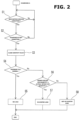
- FIG. 2 is a flowchart showing a flow of processing of the leak diagnosis A
- FIG. 5 is a flowchart showing a flow of processing of the leak diagnosis B.
- the leak diagnosis A according to the present invention is an arbitrary diagnosis that is performed additionally. Therefore, the following first describes the leak diagnosis B with reference to the flowchart of FIG. 5 .
- Step 13 a first stage diagnosis (corresponding to a first diagnosis recited in the claims) is implemented by closing the shutoff valve 24 in the fresh air induction pipe 21, and monitoring by the crank case pressure sensor 8 changes in pressure in the crank case 3 after the closing of the shutoff valve 24.
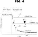
- the fresh air induction pipe 21 is blocked by the shutoff valve 24, and the negative pressure in the intake collector 17 is applied to the inside of the crank case 3 via the first blowby gas pipe 22, so that the pressure in the crank case 3 gradually falls when in normal state, namely, when no leak is present. With a leak, the pressure falling becomes insufficient. Incidentally, an inflow of fresh air through the second blowby gas pipe 23 (an inverse flow through the second blowby gas pipe 23) is prevented by the PCV valve 26.
- a line L11 indicates an example of pressure falling when in normal state
- a line L12 indicates an example of pressure falling when a leak is present.
- a pressure value P2 is set as a suitable threshold value.
- the pressure value P2 may be constant, or may be set variable in accordance with the operating condition (diagnosis start condition).
- Step 14 it is determined whether or not the pressure falls to the pressure value P2, at a time instant t2 in FIG. 6 , namely, a suitable delay time after the closing of the shutoff valve 24.
- the delay time is several seconds in this example.
- Step 14 when the answer to Step 14 is NO, it means that the first stage diagnosis determines presence of an abnormality, and in order to distinguish the out-of-system leak and the in-system leak from each other, a second stage diagnosis (corresponding to a second diagnosis recited in the claims) composed of Step 16 and the following steps is further performed.
- Step 16 it is determined whether or not a condition for permitting the second stage diagnosis is satisfied.
- the second stage diagnosis is performed under the non-supercharging condition, specifically under an operating condition in which the intake air quantity is allowed to rapidly decrease, preferably during fuel-cut operation while the vehicle is decelerating with the accelerator opening being equal to zero. In this example, at Step 16, it is determined whether or not fuel-cut operation is being performed.
- the internal combustion engine 1 is of a hybrid electric vehicle and motoring of the internal combustion engine 1 can be performed by an electric motor, it is also preferable to perform the second stage diagnosis during motoring of the internal combustion engine 1.
- the pressure control valve 18 is fully opened basically.
- Step 17 the pressure control valve 18 is controlled continuously from a fully opened state into a fully closed state, and at each state, a fully opened state intake air quantity (Qopen) and a fully closed state intake air quantity (Qclose) are measured by the air flow meter 19.
- Step 18 it is determined whether or not the fully opened state intake air quantity is equal to the fully closed state intake air quantity. This determination is substantially equal to determining whether or not the fully closed state intake air quantity is measured to be less than the fully opened state intake air quantity. This comparison in magnitude is given a suitable allowable error.
- Step 19 it is determined that a leak within the system of the blowby gas treatment device (namely, a failure such as a failure of valve operation or a failure of sealing in the system), which is not an out-of-system leak, is present. In this situation, no blowby gas flows out to the external environment, and error information is stored in a memory of the engine controller 15 without activation of the warning light 35.
- a leak within the system of the blowby gas treatment device namely, a failure such as a failure of valve operation or a failure of sealing in the system
- Step 20 it is determined that a leak to the outside of the system of the blowby gas treatment device (occurrence of a hole in piping or detachment of piping) is present. In this situation, the warning light 35 is activated for informing the driver.
- the in-system leak is typically due to closed-state sticking of the one-way valve 25 in the first blowby gas pipe 22 (state where the one-way valve 25 cannot be opened sufficiently), or due to open-state sticking of the PCV valve 26 in the second blowby gas pipe 23 (state where the inverse flow cannot be prevented).
- FIG. 8 shows a basic flow of gas (fresh air passing through the air flow meter 19 and measured) when the pressure control valve 18 is fully closed.
- fresh air fresh air passing through the air flow meter 19 and measured
- the negative pressure occurring downstream of the throttle valve 14 causes outside air to inflow via the hole and be finally induced into the combustion chambers 2.
- the outside air inflowing via the hole does not pass through the air flow meter 19, and is not measured by the air flow meter 19.
- the proportion of intake air quantity added via the hole in the pipe is larger when the pressure control valve 18 is in the fully closed state, so that the fully closed state intake air quantity measured by the air flow meter 19 is smaller than the fully opened state intake air quantity. Therefore, by performing the second stage diagnosis in addition to the first stage diagnosis, it is possible to reliably identify a leak to the outside of the system.
- FIG. 7 shows a relationship between a ratio (Qclose/Qopen) between the fully opened state intake air quantity (Qopen) and the fully closed state intake air quantity (Qclose) and an equivalent diameter of the opening of a hole in piping.
- the ratio (Qclose/Qopen) is maintained at 1 as indicated by a line L13.
- the ratio (Qclose/Qopen) becomes equal to a value smaller than 1 as indicated by a line L14, wherein the value decreases as the equivalent diameter increases.
- a threshold value is set as indicated by a line L15 in accordance with a setpoint of the equivalent diameter, wherein based on the threshold value, a leak to the outside of the system is identified.
- the second blowby gas pipe 23 is in a state allowing communication, so that the first stage diagnosis determines the pressure fall as insufficient, and the answer to Step 14 becomes NO (abnormal).
- NO abnormal
- the second stage diagnosis there is no gas movement between the system and the external environment, so that the fully opened state intake air quantity and the fully closed state intake air quantity are calculated as substantially equal to each other.
- the process proceeds to the second stage diagnosis.
- the first stage diagnosis and the second stage diagnosis may be performed individually from each other, and thereafter the results of both may be combined to obtain a similar final result of diagnosis.
- the sensing of the fully opened state intake air quantity and the sensing of the fully closed state intake air quantity are not limited to the process where they are performed in succession.
- the sensing of the fully opened state intake air quantity and the sensing of the fully closed state intake air quantity may be performed individually in respective suitable timings.
- the second stage diagnosis is performed with the pressure control valve controlled to be in the fully opened state.
- the second stage diagnosis may be implemented by controlling the pressure control valve into an open-side state (state where the valve opening is closer to the fully opened side), and using an open-side state intake air quantity measured when the pressure control valve is in the open-side state.
- the second stage diagnosis is performed with the pressure control valve controlled to be in the fully closed state. However, it is unnecessary to control the pressure control valve into the fully closed state.
- the second stage diagnosis may be implemented by controlling the pressure control valve into a closed-side state (state where the valve opening is closer to the fully closed side), and using a closed-side state intake air quantity measured when the pressure control valve is in the closed-side state.
- the leak diagnosis A is performed at a suitable frequency, for example, once a trip.
- Step 1 it is determined whether or not it is under the non-supercharging condition. This determination may be based on the load and rotational speed of the internal combustion engine 1, or may be based on determination by using the boost pressure sensor 20 whether or not the intake pressure is actually a negative pressure.
- Step 2 it is determined whether or not a diagnosis start condition is satisfied.
- the diagnosis start condition is regarded as satisfied to permit the diagnosis to be started.
- Step 3 a first stage diagnosis is implemented by closing the shutoff valve 24 in the fresh air induction pipe 21, and monitoring by the crank case pressure sensor 8 changes in pressure in the crank case 3 after the closing of the shutoff valve 24.
- the fresh air induction pipe 21 is blocked by the shutoff valve 24, and the negative pressure in the intake collector 17 is applied to the inside of the crank case 3 via the second blowby gas pipe 23, so that the pressure in the crank case 3 gradually falls when in normal state, namely, when no leak is present. With a leak, the pressure falling becomes insufficient. Incidentally, an inflow of fresh air through the first blowby gas pipe 22 (an inverse flow through the first blowby gas pipe 22) is prevented by the one-way valve 25.
- a line L1 indicates an example of pressure falling when in normal state
- a line L2 indicates an example of pressure falling when a leak is present.
- a pressure value P1 is set as a suitable threshold value.
- the pressure value P1 may be constant, or may be set variable in accordance with the operating condition (diagnosis start condition).
- Step 4 it is determined whether or not the pressure falls to the pressure value P1, at a time instant t1 in FIG. 3 , namely, a suitable delay time after the closing of the shutoff valve 24.
- the delay time is several seconds in this example.
- Step 4 when the answer to Step 4 is NO, it means that the first stage diagnosis determines presence of an abnormality, and in order to distinguish the out-of-system leak and the in-system leak from each other, a second stage diagnosis composed of Step 6 and the following steps is further performed.
- the second stage diagnosis since the second stage diagnosis is performed subsequent to the first stage diagnosis, the operating condition of the internal combustion engine 1 is under the non-supercharging condition.
- Step 6 it is determined whether or not the intake air quantity measured by the air flow meter 19 (namely, the sensed intake air quantity) is equal to an actual intake air quantity flowing into the cylinders of the internal combustion engine 1.
- This comparison is given a suitable allowable error.
- this is implemented by determining whether or not a quantity of increasing correction applied to a basic fuel injection quantity based on the sensed intake air quantity is greater than or equal to a predetermined level under a feedback control of air fuel ratio based on the air fuel ratio sensor 33.
- the injection quantity injected by the fuel injection valve (specifically, the width of injection pulsing applied to the fuel injection valve) Ti is calculated by the following mathematical expression using the basic fuel injection quantity Tp that is calculated from the sensed intake air quantity and the engine rotational speed.
- a a feedback correction coefficient that is calculated in succession by PID control or the like for convergence to the target air fuel ratio with reference to the sensing signal of the air fuel ratio sensor 33;
- am represents a correction coefficient learning value that is calculated based on a bias of the feedback correction coefficient a for correspondence to an individual deviation and a timely change, wherein the correction coefficient learning value is allocated to a map defined by load and rotational speed as parameters, and is learned and updated;
- K represents an increasing correction coefficient such as one relating to the cooling water temperature;
- Ts represents a voltage correction component corresponding to a response delay of the fuel injection valve.
- the sum (a + am) of the feedback correction coefficient a and the correction coefficient learning value am in the mathematical expression corresponds to the quantity of increasing correction applied to the basic fuel injection quantity Tp.
- the actual intake air quantity flowing into the cylinders becomes larger than the sensed intake air quantity measured by the air flow meter 19.
- the sensed intake air quantity is measured to be smaller than actual. This causes that during the air fuel ratio feedback control, a control based on the basic fuel injection quantity Tp based on the sensed intake air quantity causes the air fuel ratio to be leaner than the target air fuel ratio (for example, theoretical air fuel ratio).
- the correction quantity (a + am) is set large.
- the answer is YES, namely, it is determined that the sensed intake air quantity is equal to the actual intake air quantity.
- the answer is NO, namely, it is determined that the actual intake air quantity is larger than the sensed intake air quantity.
- Step 7 it is determined that a leak within the system of the blowby gas treatment device (namely, a failure such as a failure of valve operation or a failure of sealing in the system) is present. In this situation, no blowby gas flows out to the external environment, and error information is stored in a memory of the engine controller 15 without activation of the warning light 35.
- a leak within the system of the blowby gas treatment device namely, a failure such as a failure of valve operation or a failure of sealing in the system
- Step 6 When the answer to Step 6 is NO, namely, when it is determined at Step 6 that the actual intake air quantity is larger than the sensed intake air quantity, the process proceeds to Step 8. At Step 8, it is determined that a leak to the outside of the system of the blowby gas treatment device (occurrence of a hole in piping or detachment of piping) is present. In this situation, the warning light 35 is activated for informing the driver.
- the in-system leak is typically due to open-state sticking of the one-way valve 25 in the first blowby gas pipe 22 (state where the inverse flow cannot be prevented).
- the pressure in the crank case 3 gradually falls, as the fresh air induction pipe 21 is blocked by the shutoff valve 24 and a negative pressure is applied to the intake collector 17 via the second blowby gas pipe 23.
- the one-way valve 25 is stuck in the open state, fresh air flows from the intake passage 11 into the crank case 3 via the first blowby gas pipe 22, so that the pressure falling in the crank case 3 becomes insufficient. Accordingly, the first stage diagnosis (Step 4) determines presence of an abnormality.
- the negative pressure occurring downstream of the throttle valve 14 causes outside air to inflow via the hole and be finally induced into the combustion chambers 2.
- the outside air inflowing via the hole does not pass through the air flow meter 19, and is not measured by the air flow meter 19. Accordingly, as compared with the actual intake air quantity flowing into the cylinders of the internal combustion engine 1, the sensed intake air quantity measured by the air flow meter 19 becomes relatively small. Therefore, by performing the second stage diagnosis in addition to the first stage diagnosis, it is possible to reliably identify a leak to the outside of the system.
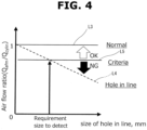
- FIG. 4 shows a relationship between a ratio (Qafm/Qcylin) between the sensed intake air quantity (Qafm) and the actual intake air quantity (Qcylin) and an equivalent diameter of the opening of a hole in piping.
- the ratio (Qafm/Qcylin) is maintained at 1 as indicated by a line L3.
- the ratio (Qafm/Qcylin) With occurrence of a hole in piping, the ratio (Qafm/Qcylin) becomes equal to a value smaller than 1 as indicated by a line L4, wherein the value decreases as the equivalent diameter increases.
- a threshold value is set as indicated by a line L5 in accordance with a setpoint of the equivalent diameter, wherein based on the threshold value, a leak to the outside of the system is identified.
- the process proceeds to the second stage diagnosis.
- the first stage diagnosis and the second stage diagnosis may be performed individually from each other, and thereafter the results of both may be combined to obtain a similar final result of diagnosis.
- the actual intake air quantity may be calculated based on the sensed value of the boost pressure sensor 20 at the intake collector 17, and compared with the sensed intake air quantity.
- the leak diagnosis A is performed under the non-supercharging condition and the leak diagnosis B is performed such that the first stage diagnosis is performed under the supercharging condition and thereafter the second stage diagnosis is performed under the non-supercharging condition (preferably, during fuel cut operation or during motoring).
- the present embodiment where the leak diagnosis A and the leak diagnosis B are both performed serves to enhance the accuracy of the leak diagnosis and reduce the frequency of incorrect determination. As required, it may be implemented by appropriately combining the result of the leak diagnosis A and the result of the leak diagnosis B.
- Step 5 in the leak diagnosis A Presence of no leak is determined
- at Step 15 in the leak diagnosis B it is possible to determine no occurrence of a hole in a pipe system including at least the fresh air induction pipe 21 and the first blowby gas pipe 22.
- open-state sticking of the one-way valve 25 can be detected by the leak diagnosis A
- closed-state sticking of the one-way valve 25 can be detected by the leak diagnosis B.
Landscapes
- Engineering & Computer Science (AREA)
- Mechanical Engineering (AREA)
- General Engineering & Computer Science (AREA)
- Chemical & Material Sciences (AREA)
- Combustion & Propulsion (AREA)
- Physics & Mathematics (AREA)
- General Physics & Mathematics (AREA)
- Lubrication Details And Ventilation Of Internal Combustion Engines (AREA)
Claims (8)
- Leckdiagnoseverfahren für eine Blowby-Gasbehandlungsvorrichtung einer Brennkraftmaschine,wobei die Blowby-Gasbehandlungsvorrichtung umfasst:eine Frischluft-Ansaugleitung (21), die zum Ansaugen von Frischluft in ein Kurbelgehäuse (3) von einem Abschnitt eines Ansaugkanals (11) stromabwärts eines Luftmengenmessers (19) strukturiert ist;ein Druckregelventil (18), das in einem Abschnitt des Ansaugkanals (11) stromaufwärts einer Drosselklappe (14) und stromaufwärts eines Kompressors (13) angeordnet ist;eine erste Blowby-Gasleitung (22), die zum Ansaugen von Blowby-Gas von dem Kurbelgehäuse (3) in einen Abschnitt des Ansaugkanals (11) zwischen dem Kompressor (13) und dem Druckregelventil (18) strukturiert ist;eine zweite Blowby-Gasleitung (23), die zum Ansaugen von Blowby-Gas von dem Kurbelgehäuse (3) in einen Abschnitt des Ansaugkanals (11) stromabwärts des Kompressors (13) und stromabwärts des Drosselventils (14) strukturiert ist;ein Absperrventil (24), das zum Blockieren der Frischluft-Ansaugleitung (21) strukturiert ist;ein Einwegventil (25), das zum Ermöglichen nur eines Gasflusses in der ersten Blowby-Gasleitung (22) von dem Kurbelgehäuse (3) zu dem Ansaugkanal (11) strukturiert ist; undein positives Kurbelgehäuse-Belüftungsventil (26), das in der zweiten Blowby-Gasleitung (23) angeordnet ist;wobei das Leckdiagnoseverfahren aufweist:Ausführen einer ersten Diagnose, um das Absperrventil (24) unter einer Aufladebedingung zu schließen und Bestimmen, ob ein Druckabfall im Kurbelgehäuse (3) nach dem Schließen des Absperrventils (24) normal oder anormal ist;Ausführen einer zweiten Diagnose zum Steuern des Drucksteuerventils (18) in einen Offenseitenzustand und einen Schließseitenzustand unter einer Nichtaufladebedingung und Bestimmen, ob eine Offenseitenzustands-Ansaugluftmenge (Qopen) gleich einer Schließseitenzustands-Ansaugluftmenge (Qclose) ist oder nicht, wobei die Offenseitenzustands-Ansaugluftmenge (Qopen) eine Menge von Ansaugluft ist, die gemessen wird, wenn sich das Drucksteuerventil (18) in dem Offenseitenzustand befindet, und wobei die Schließseitenzustands-Ansaugluftmenge (Qclose) eine Menge von Ansaugluft ist, die gemessen wird, wenn sich das Drucksteuerventil (18) in dem Schließseitenzustand befindet;Bestimmen von Vorhandensein eines Lecks zu einer Außenseite eines Systems der Blowby-Gasbehandlungsvorrichtung in Reaktion auf eine Bedingung, dass die erste Diagnose den Druckabfall als anormal bestimmt und die zweite Diagnose die Offenseitenzustands-Ansaugluftmenge (Qopen) als ungleich der Schließseitenzustands-Ansaugluftmenge (Qclose) bestimmt; undBestimmen von Vorhandensein eines Fehlers innerhalb des Systems der Blowby-Gasbehandlungsvorrichtung in Reaktion auf eine Bedingung, dass die erste Diagnose den Druckabfall als anormal bestimmt und die zweite Diagnose die Offenseitenzustands-Ansaugluftmenge (Qopen) als gleich der Schließseitenzustands-Ansaugluftmenge (Qclose) bestimmt.
- Leckdiagnoseverfahren nach Anspruch 1, umfassend:Ausführen der ersten Diagnose vor der zweiten Diagnose; undAusführen der zweiten Diagnose im Anschluss an eine Bestimmung durch die erste Diagnose, dass der Druckabfall anormal ist.
- Leckdiagnoseverfahren nach Anspruch 1 oder 2, wobei die zweite Diagnose durch kontinuierliches Steuern des Druckregelventils (18) vom Offenseitenzustand in den Schließseitenzustand und Messen der Offenseitenzustands-Ansaugluftmenge (Qopen) und der Schließseitenzustands-Ansaugluftmenge (Qclose) in jedem Zustand durchgeführt wird.
- Leckdiagnoseverfahren nach einem der Ansprüche 1 bis 3, wobei die zweite Diagnose beim Kraftstoffabsenkungsbetrieb unter Fahrzeugverlangsamung oder beim Betrieb durch eine externe Antriebskraft ausgeführt wird.
- Leckdiagnoseverfahren nach einem der Ansprüche 1 bis 4, umfassend:
Bestimmen des Fehlers innerhalb des Systems als einen Fehler aufgrund eines Feststeckens des Einwegventils (25) im geschlossenen Zustand oder eines Feststeckens des positiven Kurbelgehäuseentlüftungsventils (26) im offenen Zustand. - Leckdiagnoseverfahren nach einem der Ansprüche 1 bis 5, umfassend:Aktivieren einer Warnleuchte (35) in Reaktion auf eine Bestimmung von Vorhandensein eines Lecks nach der Außenseite des Systems der Blowby-Gasbehandlungsvorrichtung; undDeaktivieren der Warnleuchte (35) in Reaktion auf eine Bestimmung von Vorhandensein eines Fehlers innerhalb des Systems der Blowby-Gasbehandlungsvorrichtung.
- Leckdiagnoseverfahren nach einem der Ansprüche 1 bis 6, umfassend:Durchführen der zweiten Diagnose durch Steuern des Drucksteuerventils (18) in einen vollständig geöffneten Zustand und einen vollständig geschlossenen Zustand unter der Nichtaufladebedingung und Bestimmen, ob eine Ansaugluftmenge im vollständig geöffneten Zustand (Qopen) gleich einer Ansaugluftmenge im vollständig geschlossenen Zustand (Qclose) ist oder nicht,
wobei die Ansaugluftmenge im vollständig geöffneten Zustand (Qopen) eine Menge von Ansaugluft ist, die gemessen wird, wenn sich das Druckregelventil (18) in dem vollständig geöffneten Zustand befindet, und wobei die Ansaugluftmenge im vollständig geschlossenen Zustand (Qclose) eine Menge von Ansaugluft ist, die gemessen wird, wenn sich das Druckregelventil (18) in dem vollständig geschlossenen Zustand befindet;Bestimmen von Vorhandensein eines Lecks zur Außenseite des Systems der Blowby-Gasbehandlungsvorrichtung in Reaktion auf eine Bedingung, dass die erste Diagnose den Druckabfall als anormal bestimmt und die zweite Diagnose die Ansaugluftmenge im vollständig geöffneten Zustand (Qopen) als ungleich der Ansaugluftmenge im vollständig geschlossenen Zustand (Qclose) bestimmt; undBestimmen von Vorhandensein eines Fehlers innerhalb des Systems der Blowby-Gasbehandlungsvorrichtung in Reaktion auf eine Bedingung, dass die erste Diagnose den Druckabfall als anormal bestimmt und die zweite Diagnose die Ansaugluftmenge im vollständig geöffneten Zustand (Qopen) als gleich der Ansaugluftmenge im vollständig geschlossenen Zustand (Qclose) bestimmt. - Brennkraftmaschine-Blowby-Gasbehandlungsvorrichtung-Leckdiagnosevorrichtung, umfassend:eine Brennkraftmaschine, die einen Kompressor (13) in einem Ansaugkanal (11) zur Aufladung umfasst;eine Blowby-Gasbehandlungsvorrichtung, umfassend:eine Frischluft-Ansaugleitung (21), die zum Ansaugen von Frischluft in ein Kurbelgehäuse (3) von einem Abschnitt des Ansaugkanals (11) stromabwärts von einem Luftmengenmesser (19) strukturiert ist;ein Druckregelventil (18), das in einem Abschnitt des Ansaugkanals (11) stromaufwärts einer Drosselklappe (14) und stromaufwärts des Kompressors (13) angeordnet ist;eine erste Blowby-Gasleitung (22), die zum Ansaugen von Blowby-Gas von dem Kurbelgehäuse (3) in einen Abschnitt des Ansaugkanals (11) zwischen dem Kompressor (13) und dem Druckregelventil (18) strukturiert ist;eine zweite Blowby-Gasleitung (23), die zum Ansaugen von Blowby-Gas von dem Kurbelgehäuse (3) in einen Abschnitt des Ansaugkanals (11) stromabwärts des Kompressors (13) und stromabwärts des Drosselventils (14) strukturiert ist;ein Absperrventil (24), das zum Blockieren der Frischluft-Ansaugleitung (21) strukturiert ist;ein Einwegventil (25), das zum Ermöglichen nur eines Gasflusses in der ersten Blowby-Gasleitung (22) von dem Kurbelgehäuse (3) zu dem Ansaugkanal (11) strukturiert ist; undein positives Kurbelgehäuseentlüftungsventil (26), das in der zweiten Blowby-Gasleitung (23) angeordnet ist; undeinen Steuerabschnitt (15), der zum Diagnostizieren eines Lecks der Blowby-Gasbehandlungsvorrichtung konfiguriert ist, wobei der Steuerabschnitt (15) konfiguriert ist:eine erste Diagnose auszuführen, um das Absperrventil (24) unter einer Aufladebedingung zu schließen und zu bestimmen, ob ein Druckabfall in dem Kurbelgehäuse (3) nach dem Schließen des Absperrventils (24) normal oder anormal ist;eine zweite Diagnose auszuführen, um das Drucksteuerventil (18) unter einer Nichtaufladebedingung in einen Offenseitenzustand und einen Schließseitenzustand zu steuern und zu bestimmen, ob eine Offenseitenzustands-Ansaugluftmenge (Qopen) gleich einer Schließseitenzustands-Ansaugluftmenge (Qclose) ist oder nicht, wobei die Offenseitenzustands-Ansaugluftmenge (Qopen) eine Menge von Ansaugluft ist, die gemessen wird, wenn sich das Drucksteuerventil (18) im Offenseitenzustand befindet, und wobei die Schließseitenzustands-Ansaugluftmenge (Qclose) eine Menge von Ansaugluft ist, die gemessen wird, wenn sich das Drucksteuerventil (18) im Schließseitenzustand befindet;ein Vorhandensein eines Lecks zu einer Außenseite eines Systems der Blowby-Gasbehandlungsvorrichtung in Reaktion auf eine Bedingung zu bestimmen, dass die erste Diagnose den Druckabfall als anormal bestimmt und die zweite Diagnose die Offenseitenzustands-Ansaugluftmenge (Qopen) als ungleich der Schließseitenzustands-Ansaugluftmenge (Qclose) bestimmt; undein Vorhandensein eines Fehlers innerhalb des Systems der Blowby-Gasbehandlungsvorrichtung in Reaktion auf eine Bedingung zu bestimmen, dass die erste Diagnose den Druckabfall als anormal bestimmt und die zweite Diagnose die Offenseitenzustands-Ansaugluftmenge (Qopen) als gleich der Schließseitenzustands-Ansaugluftmenge (Qclose) bestimmt.
Applications Claiming Priority (1)
| Application Number | Priority Date | Filing Date | Title |
|---|---|---|---|
| PCT/JP2020/021695 WO2021245770A1 (ja) | 2020-06-02 | 2020-06-02 | 内燃機関のブローバイガス処理装置のリーク診断方法およびリーク診断装置 |
Publications (3)
| Publication Number | Publication Date |
|---|---|
| EP4159980A1 EP4159980A1 (de) | 2023-04-05 |
| EP4159980A4 EP4159980A4 (de) | 2023-07-19 |
| EP4159980B1 true EP4159980B1 (de) | 2024-08-21 |
Family
ID=78830227
Family Applications (1)
| Application Number | Title | Priority Date | Filing Date |
|---|---|---|---|
| EP20939437.8A Active EP4159980B1 (de) | 2020-06-02 | 2020-06-02 | Leckdiagnoseverfahren und leckagediagnosevorrichtung für eine blow-by-gasbehandlungsvorrichtung eines verbrennungsmotors |
Country Status (5)
| Country | Link |
|---|---|
| US (1) | US11624676B2 (de) |
| EP (1) | EP4159980B1 (de) |
| JP (1) | JP7193017B2 (de) |
| CN (1) | CN114207259B (de) |
| WO (1) | WO2021245770A1 (de) |
Families Citing this family (8)
| Publication number | Priority date | Publication date | Assignee | Title |
|---|---|---|---|---|
| EP4159980B1 (de) * | 2020-06-02 | 2024-08-21 | NISSAN MOTOR Co., Ltd. | Leckdiagnoseverfahren und leckagediagnosevorrichtung für eine blow-by-gasbehandlungsvorrichtung eines verbrennungsmotors |
| WO2021245769A1 (ja) * | 2020-06-02 | 2021-12-09 | 日産自動車株式会社 | 内燃機関のブローバイガス処理装置のリーク診断方法およびリーク診断装置 |
| JP7593106B2 (ja) * | 2020-12-28 | 2024-12-03 | ニデックパワートレインシステムズ株式会社 | ブローバイガスリーク診断装置 |
| US11959427B2 (en) * | 2022-03-04 | 2024-04-16 | Honda Motor Co., Ltd. | Leak testing apparatus |
| FR3138474B1 (fr) * | 2022-07-29 | 2024-06-14 | Psa Automobiles Sa | Systeme et procede de detection de colmatage d’un clapet antiretour de forte charge d’un moteur thermique, vehicule comprenant un tel systeme |
| FR3138475B1 (fr) * | 2022-07-29 | 2024-06-14 | Psa Automobiles Sa | Systeme et procede de detection de colmatage d’un clapet antiretour de charge partielle d’un moteur thermique, vehicule comprenant un tel systeme |
| FR3140173B1 (fr) * | 2022-09-27 | 2024-08-09 | Psa Automobiles Sa | Procédé de detection d'une fuite de gaz dans un circuit de ventilation d'un moteur thermique |
| WO2025210723A1 (ja) * | 2024-04-02 | 2025-10-09 | 日産自動車株式会社 | 車両の異常診断方法及び車両の異常診断装置 |
Family Cites Families (24)
| Publication number | Priority date | Publication date | Assignee | Title |
|---|---|---|---|---|
| CA2214740C (en) * | 1997-09-05 | 2001-11-20 | D.L.S. Cycle Products Inc. | Crankcase breather valve for engines with synchronous piston movement |
| DE10026492A1 (de) * | 2000-05-27 | 2001-11-29 | Bosch Gmbh Robert | Verfahren zur Funktionsdiagnose eines Entlüftungssystems eines Kurbelgehäuses eines Verbrennungsmotors |
| JP4535648B2 (ja) * | 2001-07-13 | 2010-09-01 | 本田技研工業株式会社 | 内燃機関の吸気系異常判定装置 |
| JP4502737B2 (ja) * | 2003-08-29 | 2010-07-14 | 本田技研工業株式会社 | 内燃機関のブローバイガス換気装置 |
| DE102006058072A1 (de) | 2006-12-07 | 2008-06-19 | Mahle International Gmbh | Kurbelgehäuseentlüftung |
| JP2008184935A (ja) * | 2007-01-29 | 2008-08-14 | Toyota Motor Corp | ブローバイガス還元装置 |
| JP2009150291A (ja) * | 2007-12-20 | 2009-07-09 | Mitsubishi Fuso Truck & Bus Corp | ブローバイガス還流装置 |
| US8020541B2 (en) * | 2009-12-15 | 2011-09-20 | GM Global Technology Operations LLC | Positive crankcase ventilation system |
| WO2011092823A1 (ja) * | 2010-01-28 | 2011-08-04 | トヨタ自動車株式会社 | 内燃機関の制御装置、及びブローバイガスとともに吸気通路に還流されるNOxの質量流量の計測装置 |
| US9260990B2 (en) * | 2012-09-14 | 2016-02-16 | Ford Global Technologies, Llc | Crankcase integrity breach detection |
| US9068486B2 (en) * | 2012-09-14 | 2015-06-30 | Ford Global Technologies, Llc | Crankcase integrity breach detection |
| US9382825B2 (en) * | 2013-04-25 | 2016-07-05 | Ford Global Technologies, Llc | System and method for gas purge control |
| CN104265401A (zh) * | 2014-09-24 | 2015-01-07 | 湖南省力宇燃气动力有限公司 | 一种进气系统带节气门多缸内燃机曲轴箱用的双向通气阀 |
| DE102015007513B4 (de) * | 2015-06-11 | 2021-09-30 | Volkswagen Aktiengesellschaft | Verfahren zur Leckageerfassung einer Kurbelgehäuseentlüftung |
| JP6332177B2 (ja) * | 2015-07-14 | 2018-05-30 | トヨタ自動車株式会社 | 内燃機関のブローバイガス還流装置 |
| JP6354714B2 (ja) * | 2015-09-04 | 2018-07-11 | 株式会社デンソー | 過給機付き内燃機関の異常診断装置 |
| JP6582863B2 (ja) * | 2015-10-20 | 2019-10-02 | アイシン精機株式会社 | 過給機付き内燃機関の吸気システム |
| JP2017115584A (ja) * | 2015-12-21 | 2017-06-29 | 株式会社デンソー | 内燃機関の異常検出装置 |
| JP6270890B2 (ja) * | 2016-03-17 | 2018-01-31 | 株式会社Subaru | リーク検出装置 |
| JP6673790B2 (ja) | 2016-09-14 | 2020-03-25 | 愛三工業株式会社 | エンジンシステム |
| JP6409086B1 (ja) * | 2017-03-30 | 2018-10-17 | 株式会社Subaru | リーク検出装置 |
| JP2019019800A (ja) * | 2017-07-21 | 2019-02-07 | 愛三工業株式会社 | 低圧ループ式egr装置を備えた過給機付きエンジンにおけるブローバイガス還元装置の異常診断装置 |
| WO2021245769A1 (ja) * | 2020-06-02 | 2021-12-09 | 日産自動車株式会社 | 内燃機関のブローバイガス処理装置のリーク診断方法およびリーク診断装置 |
| EP4159980B1 (de) * | 2020-06-02 | 2024-08-21 | NISSAN MOTOR Co., Ltd. | Leckdiagnoseverfahren und leckagediagnosevorrichtung für eine blow-by-gasbehandlungsvorrichtung eines verbrennungsmotors |
-
2020
- 2020-06-02 EP EP20939437.8A patent/EP4159980B1/de active Active
- 2020-06-02 US US17/632,636 patent/US11624676B2/en active Active
- 2020-06-02 JP JP2021575959A patent/JP7193017B2/ja active Active
- 2020-06-02 WO PCT/JP2020/021695 patent/WO2021245770A1/ja not_active Ceased
- 2020-06-02 CN CN202080055120.5A patent/CN114207259B/zh active Active
Also Published As
| Publication number | Publication date |
|---|---|
| WO2021245770A1 (ja) | 2021-12-09 |
| EP4159980A1 (de) | 2023-04-05 |
| US20220291074A1 (en) | 2022-09-15 |
| US11624676B2 (en) | 2023-04-11 |
| CN114207259B (zh) | 2024-01-30 |
| JPWO2021245770A1 (de) | 2021-12-09 |
| EP4159980A4 (de) | 2023-07-19 |
| CN114207259A (zh) | 2022-03-18 |
| JP7193017B2 (ja) | 2022-12-20 |
Similar Documents
| Publication | Publication Date | Title |
|---|---|---|
| EP4159980B1 (de) | Leckdiagnoseverfahren und leckagediagnosevorrichtung für eine blow-by-gasbehandlungsvorrichtung eines verbrennungsmotors | |
| EP4159979B1 (de) | Leckdiagnoseverfahren und leckagediagnosevorrichtung für eine blow-by-gasbehandlungsvorrichtung für einen verbrennungsmotor | |
| US6687601B2 (en) | System for diagnosing an air handling mechanism of an internal combustion engine | |
| CN109715924B (zh) | 用于对曲柄壳体排气装置的功能性进行可信性检验的方法和装置 | |
| US9714590B2 (en) | Crankcase integrity breach detection | |
| USRE50153E1 (en) | EGR apparatus of engine | |
| US20210348532A1 (en) | Method And Device For Checking The Functionality Of A Crankcase Ventilation System Of An Internal Combustion Engine | |
| US8463490B2 (en) | Method and device for diagnosing an intake tract of an internal combustion engine | |
| US9020736B2 (en) | Fault diagnosis apparatus for airflow meter | |
| EP3569847B1 (de) | Verfahren zur steuerung eines verbrennungsmotors und vorrichtung zur steuerung eines verbrennungsmotors | |
| JP2019019800A (ja) | 低圧ループ式egr装置を備えた過給機付きエンジンにおけるブローバイガス還元装置の異常診断装置 | |
| US9541016B2 (en) | Throttle control device for internal combustion engine and throttle control method for internal combustion engine | |
| US4875456A (en) | Self-diagnosis system for auxiliary air control system of internal combustion engine | |
| US6886399B2 (en) | Method for determining mass flows into the inlet manifold of an internal combustion engine | |
| US10975779B2 (en) | Engine system for determining abnormalities in an exhaust gas recirculation valve | |
| JP6679554B2 (ja) | 内燃機関の制御装置 | |
| JP4466518B2 (ja) | 過給機付きエンジンの制御装置 | |
| JP6743210B1 (ja) | 内燃機関の異常判定装置 | |
| CN113302392A (zh) | 用于检查内燃发动机的曲轴箱通风系统的功能性的方法和装置 | |
| WO2021166056A1 (ja) | 蒸発燃料処理装置の故障診断方法および故障診断装置 | |
| JP3509361B2 (ja) | 内燃機関の吸入空気流量制御装置 | |
| JP2018091300A (ja) | 吸気系機器の異常診断装置 | |
| JPH09256882A (ja) | ディーゼル機関用非常停止装置 |
Legal Events
| Date | Code | Title | Description |
|---|---|---|---|
| STAA | Information on the status of an ep patent application or granted ep patent |
Free format text: STATUS: THE INTERNATIONAL PUBLICATION HAS BEEN MADE |
|
| PUAI | Public reference made under article 153(3) epc to a published international application that has entered the european phase |
Free format text: ORIGINAL CODE: 0009012 |
|
| STAA | Information on the status of an ep patent application or granted ep patent |
Free format text: STATUS: REQUEST FOR EXAMINATION WAS MADE |
|
| 17P | Request for examination filed |
Effective date: 20220125 |
|
| AK | Designated contracting states |
Kind code of ref document: A1 Designated state(s): AL AT BE BG CH CY CZ DE DK EE ES FI FR GB GR HR HU IE IS IT LI LT LU LV MC MK MT NL NO PL PT RO RS SE SI SK SM TR |
|
| A4 | Supplementary search report drawn up and despatched |
Effective date: 20230621 |
|
| RIC1 | Information provided on ipc code assigned before grant |
Ipc: F02M 25/06 20160101ALI20230615BHEP Ipc: G01M 3/28 20060101ALI20230615BHEP Ipc: F01M 13/02 20060101ALI20230615BHEP Ipc: F02D 41/22 20060101ALI20230615BHEP Ipc: F02D 41/18 20060101ALI20230615BHEP Ipc: F02D 41/12 20060101ALI20230615BHEP Ipc: F02D 41/00 20060101ALI20230615BHEP Ipc: F01M 13/00 20060101AFI20230615BHEP |
|
| DAV | Request for validation of the european patent (deleted) | ||
| DAX | Request for extension of the european patent (deleted) | ||
| GRAP | Despatch of communication of intention to grant a patent |
Free format text: ORIGINAL CODE: EPIDOSNIGR1 |
|
| STAA | Information on the status of an ep patent application or granted ep patent |
Free format text: STATUS: GRANT OF PATENT IS INTENDED |
|
| GRAS | Grant fee paid |
Free format text: ORIGINAL CODE: EPIDOSNIGR3 |
|
| GRAA | (expected) grant |
Free format text: ORIGINAL CODE: 0009210 |
|
| STAA | Information on the status of an ep patent application or granted ep patent |
Free format text: STATUS: THE PATENT HAS BEEN GRANTED |
|
| INTG | Intention to grant announced |
Effective date: 20240625 |
|
| AK | Designated contracting states |
Kind code of ref document: B1 Designated state(s): AL AT BE BG CH CY CZ DE DK EE ES FI FR GB GR HR HU IE IS IT LI LT LU LV MC MK MT NL NO PL PT RO RS SE SI SK SM TR |
|
| REG | Reference to a national code |
Ref country code: GB Ref legal event code: FG4D |
|
| REG | Reference to a national code |
Ref country code: CH Ref legal event code: EP |
|
| REG | Reference to a national code |
Ref country code: IE Ref legal event code: FG4D |
|
| REG | Reference to a national code |
Ref country code: DE Ref legal event code: R096 Ref document number: 602020036469 Country of ref document: DE |
|
| REG | Reference to a national code |
Ref country code: LT Ref legal event code: MG9D |
|
| REG | Reference to a national code |
Ref country code: NL Ref legal event code: MP Effective date: 20240821 |
|
| PG25 | Lapsed in a contracting state [announced via postgrant information from national office to epo] |
Ref country code: NO Free format text: LAPSE BECAUSE OF FAILURE TO SUBMIT A TRANSLATION OF THE DESCRIPTION OR TO PAY THE FEE WITHIN THE PRESCRIBED TIME-LIMIT Effective date: 20241121 |
|
| REG | Reference to a national code |
Ref country code: AT Ref legal event code: MK05 Ref document number: 1715666 Country of ref document: AT Kind code of ref document: T Effective date: 20240821 |
|
| PG25 | Lapsed in a contracting state [announced via postgrant information from national office to epo] |
Ref country code: NL Free format text: LAPSE BECAUSE OF FAILURE TO SUBMIT A TRANSLATION OF THE DESCRIPTION OR TO PAY THE FEE WITHIN THE PRESCRIBED TIME-LIMIT Effective date: 20240821 Ref country code: PL Free format text: LAPSE BECAUSE OF FAILURE TO SUBMIT A TRANSLATION OF THE DESCRIPTION OR TO PAY THE FEE WITHIN THE PRESCRIBED TIME-LIMIT Effective date: 20240821 Ref country code: GR Free format text: LAPSE BECAUSE OF FAILURE TO SUBMIT A TRANSLATION OF THE DESCRIPTION OR TO PAY THE FEE WITHIN THE PRESCRIBED TIME-LIMIT Effective date: 20241122 Ref country code: FI Free format text: LAPSE BECAUSE OF FAILURE TO SUBMIT A TRANSLATION OF THE DESCRIPTION OR TO PAY THE FEE WITHIN THE PRESCRIBED TIME-LIMIT Effective date: 20240821 Ref country code: PT Free format text: LAPSE BECAUSE OF FAILURE TO SUBMIT A TRANSLATION OF THE DESCRIPTION OR TO PAY THE FEE WITHIN THE PRESCRIBED TIME-LIMIT Effective date: 20241223 |
|
| PG25 | Lapsed in a contracting state [announced via postgrant information from national office to epo] |
Ref country code: BG Free format text: LAPSE BECAUSE OF FAILURE TO SUBMIT A TRANSLATION OF THE DESCRIPTION OR TO PAY THE FEE WITHIN THE PRESCRIBED TIME-LIMIT Effective date: 20240821 |
|
| PG25 | Lapsed in a contracting state [announced via postgrant information from national office to epo] |
Ref country code: LV Free format text: LAPSE BECAUSE OF FAILURE TO SUBMIT A TRANSLATION OF THE DESCRIPTION OR TO PAY THE FEE WITHIN THE PRESCRIBED TIME-LIMIT Effective date: 20240821 |
|
| PG25 | Lapsed in a contracting state [announced via postgrant information from national office to epo] |
Ref country code: IS Free format text: LAPSE BECAUSE OF FAILURE TO SUBMIT A TRANSLATION OF THE DESCRIPTION OR TO PAY THE FEE WITHIN THE PRESCRIBED TIME-LIMIT Effective date: 20241221 Ref country code: AT Free format text: LAPSE BECAUSE OF FAILURE TO SUBMIT A TRANSLATION OF THE DESCRIPTION OR TO PAY THE FEE WITHIN THE PRESCRIBED TIME-LIMIT Effective date: 20240821 |
|
| PG25 | Lapsed in a contracting state [announced via postgrant information from national office to epo] |
Ref country code: HR Free format text: LAPSE BECAUSE OF FAILURE TO SUBMIT A TRANSLATION OF THE DESCRIPTION OR TO PAY THE FEE WITHIN THE PRESCRIBED TIME-LIMIT Effective date: 20240821 |
|
| PG25 | Lapsed in a contracting state [announced via postgrant information from national office to epo] |
Ref country code: RS Free format text: LAPSE BECAUSE OF FAILURE TO SUBMIT A TRANSLATION OF THE DESCRIPTION OR TO PAY THE FEE WITHIN THE PRESCRIBED TIME-LIMIT Effective date: 20241121 Ref country code: ES Free format text: LAPSE BECAUSE OF FAILURE TO SUBMIT A TRANSLATION OF THE DESCRIPTION OR TO PAY THE FEE WITHIN THE PRESCRIBED TIME-LIMIT Effective date: 20240821 |
|
| PG25 | Lapsed in a contracting state [announced via postgrant information from national office to epo] |
Ref country code: RS Free format text: LAPSE BECAUSE OF FAILURE TO SUBMIT A TRANSLATION OF THE DESCRIPTION OR TO PAY THE FEE WITHIN THE PRESCRIBED TIME-LIMIT Effective date: 20241121 Ref country code: PT Free format text: LAPSE BECAUSE OF FAILURE TO SUBMIT A TRANSLATION OF THE DESCRIPTION OR TO PAY THE FEE WITHIN THE PRESCRIBED TIME-LIMIT Effective date: 20241223 Ref country code: PL Free format text: LAPSE BECAUSE OF FAILURE TO SUBMIT A TRANSLATION OF THE DESCRIPTION OR TO PAY THE FEE WITHIN THE PRESCRIBED TIME-LIMIT Effective date: 20240821 Ref country code: NO Free format text: LAPSE BECAUSE OF FAILURE TO SUBMIT A TRANSLATION OF THE DESCRIPTION OR TO PAY THE FEE WITHIN THE PRESCRIBED TIME-LIMIT Effective date: 20241121 Ref country code: NL Free format text: LAPSE BECAUSE OF FAILURE TO SUBMIT A TRANSLATION OF THE DESCRIPTION OR TO PAY THE FEE WITHIN THE PRESCRIBED TIME-LIMIT Effective date: 20240821 Ref country code: LV Free format text: LAPSE BECAUSE OF FAILURE TO SUBMIT A TRANSLATION OF THE DESCRIPTION OR TO PAY THE FEE WITHIN THE PRESCRIBED TIME-LIMIT Effective date: 20240821 Ref country code: IS Free format text: LAPSE BECAUSE OF FAILURE TO SUBMIT A TRANSLATION OF THE DESCRIPTION OR TO PAY THE FEE WITHIN THE PRESCRIBED TIME-LIMIT Effective date: 20241221 Ref country code: HR Free format text: LAPSE BECAUSE OF FAILURE TO SUBMIT A TRANSLATION OF THE DESCRIPTION OR TO PAY THE FEE WITHIN THE PRESCRIBED TIME-LIMIT Effective date: 20240821 Ref country code: GR Free format text: LAPSE BECAUSE OF FAILURE TO SUBMIT A TRANSLATION OF THE DESCRIPTION OR TO PAY THE FEE WITHIN THE PRESCRIBED TIME-LIMIT Effective date: 20241122 Ref country code: FI Free format text: LAPSE BECAUSE OF FAILURE TO SUBMIT A TRANSLATION OF THE DESCRIPTION OR TO PAY THE FEE WITHIN THE PRESCRIBED TIME-LIMIT Effective date: 20240821 Ref country code: ES Free format text: LAPSE BECAUSE OF FAILURE TO SUBMIT A TRANSLATION OF THE DESCRIPTION OR TO PAY THE FEE WITHIN THE PRESCRIBED TIME-LIMIT Effective date: 20240821 Ref country code: BG Free format text: LAPSE BECAUSE OF FAILURE TO SUBMIT A TRANSLATION OF THE DESCRIPTION OR TO PAY THE FEE WITHIN THE PRESCRIBED TIME-LIMIT Effective date: 20240821 Ref country code: AT Free format text: LAPSE BECAUSE OF FAILURE TO SUBMIT A TRANSLATION OF THE DESCRIPTION OR TO PAY THE FEE WITHIN THE PRESCRIBED TIME-LIMIT Effective date: 20240821 |
|
| PG25 | Lapsed in a contracting state [announced via postgrant information from national office to epo] |
Ref country code: DK Free format text: LAPSE BECAUSE OF FAILURE TO SUBMIT A TRANSLATION OF THE DESCRIPTION OR TO PAY THE FEE WITHIN THE PRESCRIBED TIME-LIMIT Effective date: 20240821 Ref country code: SM Free format text: LAPSE BECAUSE OF FAILURE TO SUBMIT A TRANSLATION OF THE DESCRIPTION OR TO PAY THE FEE WITHIN THE PRESCRIBED TIME-LIMIT Effective date: 20240821 Ref country code: RO Free format text: LAPSE BECAUSE OF FAILURE TO SUBMIT A TRANSLATION OF THE DESCRIPTION OR TO PAY THE FEE WITHIN THE PRESCRIBED TIME-LIMIT Effective date: 20240821 |
|
| PG25 | Lapsed in a contracting state [announced via postgrant information from national office to epo] |
Ref country code: EE Free format text: LAPSE BECAUSE OF FAILURE TO SUBMIT A TRANSLATION OF THE DESCRIPTION OR TO PAY THE FEE WITHIN THE PRESCRIBED TIME-LIMIT Effective date: 20240821 |
|
| PG25 | Lapsed in a contracting state [announced via postgrant information from national office to epo] |
Ref country code: CZ Free format text: LAPSE BECAUSE OF FAILURE TO SUBMIT A TRANSLATION OF THE DESCRIPTION OR TO PAY THE FEE WITHIN THE PRESCRIBED TIME-LIMIT Effective date: 20240821 |
|
| PG25 | Lapsed in a contracting state [announced via postgrant information from national office to epo] |
Ref country code: SK Free format text: LAPSE BECAUSE OF FAILURE TO SUBMIT A TRANSLATION OF THE DESCRIPTION OR TO PAY THE FEE WITHIN THE PRESCRIBED TIME-LIMIT Effective date: 20240821 Ref country code: IT Free format text: LAPSE BECAUSE OF FAILURE TO SUBMIT A TRANSLATION OF THE DESCRIPTION OR TO PAY THE FEE WITHIN THE PRESCRIBED TIME-LIMIT Effective date: 20240821 |
|
| REG | Reference to a national code |
Ref country code: DE Ref legal event code: R097 Ref document number: 602020036469 Country of ref document: DE |
|
| PLBE | No opposition filed within time limit |
Free format text: ORIGINAL CODE: 0009261 |
|
| STAA | Information on the status of an ep patent application or granted ep patent |
Free format text: STATUS: NO OPPOSITION FILED WITHIN TIME LIMIT |
|
| PGFP | Annual fee paid to national office [announced via postgrant information from national office to epo] |
Ref country code: DE Payment date: 20250402 Year of fee payment: 6 |
|
| PGFP | Annual fee paid to national office [announced via postgrant information from national office to epo] |
Ref country code: GB Payment date: 20250401 Year of fee payment: 6 |
|
| PGFP | Annual fee paid to national office [announced via postgrant information from national office to epo] |
Ref country code: FR Payment date: 20250401 Year of fee payment: 6 |
|
| 26N | No opposition filed |
Effective date: 20250522 |
|
| PG25 | Lapsed in a contracting state [announced via postgrant information from national office to epo] |
Ref country code: SE Free format text: LAPSE BECAUSE OF FAILURE TO SUBMIT A TRANSLATION OF THE DESCRIPTION OR TO PAY THE FEE WITHIN THE PRESCRIBED TIME-LIMIT Effective date: 20240821 |
|
| REG | Reference to a national code |
Ref country code: CH Ref legal event code: H13 Free format text: ST27 STATUS EVENT CODE: U-0-0-H10-H13 (AS PROVIDED BY THE NATIONAL OFFICE) Effective date: 20260127 |
|
| PG25 | Lapsed in a contracting state [announced via postgrant information from national office to epo] |
Ref country code: MC Free format text: LAPSE BECAUSE OF FAILURE TO SUBMIT A TRANSLATION OF THE DESCRIPTION OR TO PAY THE FEE WITHIN THE PRESCRIBED TIME-LIMIT Effective date: 20240821 |
|
| PG25 | Lapsed in a contracting state [announced via postgrant information from national office to epo] |
Ref country code: LU Free format text: LAPSE BECAUSE OF NON-PAYMENT OF DUE FEES Effective date: 20250602 |
|
| REG | Reference to a national code |
Ref country code: BE Ref legal event code: MM Effective date: 20250630 |