EP4159968A2 - Antrieb für eine klappe - Google Patents
Antrieb für eine klappe Download PDFInfo
- Publication number
- EP4159968A2 EP4159968A2 EP22198797.7A EP22198797A EP4159968A2 EP 4159968 A2 EP4159968 A2 EP 4159968A2 EP 22198797 A EP22198797 A EP 22198797A EP 4159968 A2 EP4159968 A2 EP 4159968A2
- Authority
- EP
- European Patent Office
- Prior art keywords
- drive
- rotor
- motor
- spindle
- housing
- Prior art date
- Legal status (The legal status is an assumption and is not a legal conclusion. Google has not performed a legal analysis and makes no representation as to the accuracy of the status listed.)
- Granted
Links
Images




Classifications
-
- E—FIXED CONSTRUCTIONS
- E05—LOCKS; KEYS; WINDOW OR DOOR FITTINGS; SAFES
- E05F—DEVICES FOR MOVING WINGS INTO OPEN OR CLOSED POSITION; CHECKS FOR WINGS; WING FITTINGS NOT OTHERWISE PROVIDED FOR, CONCERNED WITH THE FUNCTIONING OF THE WING
- E05F15/00—Power-operated mechanisms for wings
- E05F15/60—Power-operated mechanisms for wings using electrical actuators
- E05F15/603—Power-operated mechanisms for wings using electrical actuators using rotary electromotors
- E05F15/611—Power-operated mechanisms for wings using electrical actuators using rotary electromotors for swinging wings
- E05F15/616—Power-operated mechanisms for wings using electrical actuators using rotary electromotors for swinging wings operated by push-pull mechanisms
- E05F15/622—Power-operated mechanisms for wings using electrical actuators using rotary electromotors for swinging wings operated by push-pull mechanisms using screw-and-nut mechanisms
-
- E—FIXED CONSTRUCTIONS
- E05—LOCKS; KEYS; WINDOW OR DOOR FITTINGS; SAFES
- E05F—DEVICES FOR MOVING WINGS INTO OPEN OR CLOSED POSITION; CHECKS FOR WINGS; WING FITTINGS NOT OTHERWISE PROVIDED FOR, CONCERNED WITH THE FUNCTIONING OF THE WING
- E05F15/00—Power-operated mechanisms for wings
- E05F15/40—Safety devices, e.g. detection of obstructions or end positions
- E05F15/41—Detection by monitoring transmitted force or torque; Safety couplings with activation dependent upon torque or force, e.g. slip couplings
-
- F—MECHANICAL ENGINEERING; LIGHTING; HEATING; WEAPONS; BLASTING
- F16—ENGINEERING ELEMENTS AND UNITS; GENERAL MEASURES FOR PRODUCING AND MAINTAINING EFFECTIVE FUNCTIONING OF MACHINES OR INSTALLATIONS; THERMAL INSULATION IN GENERAL
- F16H—GEARING
- F16H25/00—Gearings comprising primarily only cams, cam-followers and screw-and-nut mechanisms
- F16H25/18—Gearings comprising primarily only cams, cam-followers and screw-and-nut mechanisms for conveying or interconverting oscillating or reciprocating motions
- F16H25/20—Screw mechanisms
-
- F—MECHANICAL ENGINEERING; LIGHTING; HEATING; WEAPONS; BLASTING
- F16—ENGINEERING ELEMENTS AND UNITS; GENERAL MEASURES FOR PRODUCING AND MAINTAINING EFFECTIVE FUNCTIONING OF MACHINES OR INSTALLATIONS; THERMAL INSULATION IN GENERAL
- F16H—GEARING
- F16H25/00—Gearings comprising primarily only cams, cam-followers and screw-and-nut mechanisms
- F16H25/18—Gearings comprising primarily only cams, cam-followers and screw-and-nut mechanisms for conveying or interconverting oscillating or reciprocating motions
- F16H25/20—Screw mechanisms
- F16H25/2021—Screw mechanisms with means for avoiding overloading
-
- F—MECHANICAL ENGINEERING; LIGHTING; HEATING; WEAPONS; BLASTING
- F16—ENGINEERING ELEMENTS AND UNITS; GENERAL MEASURES FOR PRODUCING AND MAINTAINING EFFECTIVE FUNCTIONING OF MACHINES OR INSTALLATIONS; THERMAL INSULATION IN GENERAL
- F16H—GEARING
- F16H57/00—General details of gearing
- F16H57/02—Gearboxes; Mounting gearing therein
- F16H57/025—Support of gearboxes, e.g. torque arms, or attachment to other devices
-
- E—FIXED CONSTRUCTIONS
- E05—LOCKS; KEYS; WINDOW OR DOOR FITTINGS; SAFES
- E05F—DEVICES FOR MOVING WINGS INTO OPEN OR CLOSED POSITION; CHECKS FOR WINGS; WING FITTINGS NOT OTHERWISE PROVIDED FOR, CONCERNED WITH THE FUNCTIONING OF THE WING
- E05F5/00—Braking devices, e.g. checks; Stops; Buffers
-
- E—FIXED CONSTRUCTIONS
- E05—LOCKS; KEYS; WINDOW OR DOOR FITTINGS; SAFES
- E05Y—INDEXING SCHEME ASSOCIATED WITH SUBCLASSES E05D AND E05F, RELATING TO CONSTRUCTION ELEMENTS, ELECTRIC CONTROL, POWER SUPPLY, POWER SIGNAL OR TRANSMISSION, USER INTERFACES, MOUNTING OR COUPLING, DETAILS, ACCESSORIES, AUXILIARY OPERATIONS NOT OTHERWISE PROVIDED FOR, APPLICATION THEREOF
- E05Y2201/00—Constructional elements; Accessories therefor
- E05Y2201/10—Covers; Housings
- E05Y2201/11—Covers
-
- E—FIXED CONSTRUCTIONS
- E05—LOCKS; KEYS; WINDOW OR DOOR FITTINGS; SAFES
- E05Y—INDEXING SCHEME ASSOCIATED WITH SUBCLASSES E05D AND E05F, RELATING TO CONSTRUCTION ELEMENTS, ELECTRIC CONTROL, POWER SUPPLY, POWER SIGNAL OR TRANSMISSION, USER INTERFACES, MOUNTING OR COUPLING, DETAILS, ACCESSORIES, AUXILIARY OPERATIONS NOT OTHERWISE PROVIDED FOR, APPLICATION THEREOF
- E05Y2201/00—Constructional elements; Accessories therefor
- E05Y2201/20—Brakes; Disengaging means; Holders; Stops; Valves; Accessories therefor
- E05Y2201/21—Brakes
-
- E—FIXED CONSTRUCTIONS
- E05—LOCKS; KEYS; WINDOW OR DOOR FITTINGS; SAFES
- E05Y—INDEXING SCHEME ASSOCIATED WITH SUBCLASSES E05D AND E05F, RELATING TO CONSTRUCTION ELEMENTS, ELECTRIC CONTROL, POWER SUPPLY, POWER SIGNAL OR TRANSMISSION, USER INTERFACES, MOUNTING OR COUPLING, DETAILS, ACCESSORIES, AUXILIARY OPERATIONS NOT OTHERWISE PROVIDED FOR, APPLICATION THEREOF
- E05Y2201/00—Constructional elements; Accessories therefor
- E05Y2201/20—Brakes; Disengaging means; Holders; Stops; Valves; Accessories therefor
- E05Y2201/214—Disengaging means
- E05Y2201/216—Clutches
-
- E—FIXED CONSTRUCTIONS
- E05—LOCKS; KEYS; WINDOW OR DOOR FITTINGS; SAFES
- E05Y—INDEXING SCHEME ASSOCIATED WITH SUBCLASSES E05D AND E05F, RELATING TO CONSTRUCTION ELEMENTS, ELECTRIC CONTROL, POWER SUPPLY, POWER SIGNAL OR TRANSMISSION, USER INTERFACES, MOUNTING OR COUPLING, DETAILS, ACCESSORIES, AUXILIARY OPERATIONS NOT OTHERWISE PROVIDED FOR, APPLICATION THEREOF
- E05Y2201/00—Constructional elements; Accessories therefor
- E05Y2201/20—Brakes; Disengaging means; Holders; Stops; Valves; Accessories therefor
- E05Y2201/23—Actuation thereof
- E05Y2201/232—Actuation thereof by automatically acting means
- E05Y2201/236—Actuation thereof by automatically acting means using force or torque
-
- E—FIXED CONSTRUCTIONS
- E05—LOCKS; KEYS; WINDOW OR DOOR FITTINGS; SAFES
- E05Y—INDEXING SCHEME ASSOCIATED WITH SUBCLASSES E05D AND E05F, RELATING TO CONSTRUCTION ELEMENTS, ELECTRIC CONTROL, POWER SUPPLY, POWER SIGNAL OR TRANSMISSION, USER INTERFACES, MOUNTING OR COUPLING, DETAILS, ACCESSORIES, AUXILIARY OPERATIONS NOT OTHERWISE PROVIDED FOR, APPLICATION THEREOF
- E05Y2201/00—Constructional elements; Accessories therefor
- E05Y2201/40—Motors; Magnets; Springs; Weights; Accessories therefor
- E05Y2201/404—Function thereof
- E05Y2201/41—Function thereof for closing
-
- E—FIXED CONSTRUCTIONS
- E05—LOCKS; KEYS; WINDOW OR DOOR FITTINGS; SAFES
- E05Y—INDEXING SCHEME ASSOCIATED WITH SUBCLASSES E05D AND E05F, RELATING TO CONSTRUCTION ELEMENTS, ELECTRIC CONTROL, POWER SUPPLY, POWER SIGNAL OR TRANSMISSION, USER INTERFACES, MOUNTING OR COUPLING, DETAILS, ACCESSORIES, AUXILIARY OPERATIONS NOT OTHERWISE PROVIDED FOR, APPLICATION THEREOF
- E05Y2201/00—Constructional elements; Accessories therefor
- E05Y2201/40—Motors; Magnets; Springs; Weights; Accessories therefor
- E05Y2201/404—Function thereof
- E05Y2201/422—Function thereof for opening
-
- E—FIXED CONSTRUCTIONS
- E05—LOCKS; KEYS; WINDOW OR DOOR FITTINGS; SAFES
- E05Y—INDEXING SCHEME ASSOCIATED WITH SUBCLASSES E05D AND E05F, RELATING TO CONSTRUCTION ELEMENTS, ELECTRIC CONTROL, POWER SUPPLY, POWER SIGNAL OR TRANSMISSION, USER INTERFACES, MOUNTING OR COUPLING, DETAILS, ACCESSORIES, AUXILIARY OPERATIONS NOT OTHERWISE PROVIDED FOR, APPLICATION THEREOF
- E05Y2201/00—Constructional elements; Accessories therefor
- E05Y2201/40—Motors; Magnets; Springs; Weights; Accessories therefor
- E05Y2201/43—Motors
- E05Y2201/434—Electromotors; Details thereof
-
- E—FIXED CONSTRUCTIONS
- E05—LOCKS; KEYS; WINDOW OR DOOR FITTINGS; SAFES
- E05Y—INDEXING SCHEME ASSOCIATED WITH SUBCLASSES E05D AND E05F, RELATING TO CONSTRUCTION ELEMENTS, ELECTRIC CONTROL, POWER SUPPLY, POWER SIGNAL OR TRANSMISSION, USER INTERFACES, MOUNTING OR COUPLING, DETAILS, ACCESSORIES, AUXILIARY OPERATIONS NOT OTHERWISE PROVIDED FOR, APPLICATION THEREOF
- E05Y2201/00—Constructional elements; Accessories therefor
- E05Y2201/60—Suspension or transmission members; Accessories therefor
- E05Y2201/604—Transmission members
-
- E—FIXED CONSTRUCTIONS
- E05—LOCKS; KEYS; WINDOW OR DOOR FITTINGS; SAFES
- E05Y—INDEXING SCHEME ASSOCIATED WITH SUBCLASSES E05D AND E05F, RELATING TO CONSTRUCTION ELEMENTS, ELECTRIC CONTROL, POWER SUPPLY, POWER SIGNAL OR TRANSMISSION, USER INTERFACES, MOUNTING OR COUPLING, DETAILS, ACCESSORIES, AUXILIARY OPERATIONS NOT OTHERWISE PROVIDED FOR, APPLICATION THEREOF
- E05Y2201/00—Constructional elements; Accessories therefor
- E05Y2201/60—Suspension or transmission members; Accessories therefor
- E05Y2201/622—Suspension or transmission members elements
- E05Y2201/696—Screw mechanisms
-
- E—FIXED CONSTRUCTIONS
- E05—LOCKS; KEYS; WINDOW OR DOOR FITTINGS; SAFES
- E05Y—INDEXING SCHEME ASSOCIATED WITH SUBCLASSES E05D AND E05F, RELATING TO CONSTRUCTION ELEMENTS, ELECTRIC CONTROL, POWER SUPPLY, POWER SIGNAL OR TRANSMISSION, USER INTERFACES, MOUNTING OR COUPLING, DETAILS, ACCESSORIES, AUXILIARY OPERATIONS NOT OTHERWISE PROVIDED FOR, APPLICATION THEREOF
- E05Y2400/00—Electronic control; Electrical power; Power supply; Power or signal transmission; User interfaces
- E05Y2400/10—Electronic control
- E05Y2400/32—Position control, detection or monitoring
- E05Y2400/334—Position control, detection or monitoring by using pulse generators
- E05Y2400/336—Position control, detection or monitoring by using pulse generators of the angular type
-
- E—FIXED CONSTRUCTIONS
- E05—LOCKS; KEYS; WINDOW OR DOOR FITTINGS; SAFES
- E05Y—INDEXING SCHEME ASSOCIATED WITH SUBCLASSES E05D AND E05F, RELATING TO CONSTRUCTION ELEMENTS, ELECTRIC CONTROL, POWER SUPPLY, POWER SIGNAL OR TRANSMISSION, USER INTERFACES, MOUNTING OR COUPLING, DETAILS, ACCESSORIES, AUXILIARY OPERATIONS NOT OTHERWISE PROVIDED FOR, APPLICATION THEREOF
- E05Y2600/00—Mounting or coupling arrangements for elements provided for in this subclass
- E05Y2600/40—Mounting location; Visibility of the elements
- E05Y2600/454—Mounting location; Visibility of the elements in or on the motor
-
- E—FIXED CONSTRUCTIONS
- E05—LOCKS; KEYS; WINDOW OR DOOR FITTINGS; SAFES
- E05Y—INDEXING SCHEME ASSOCIATED WITH SUBCLASSES E05D AND E05F, RELATING TO CONSTRUCTION ELEMENTS, ELECTRIC CONTROL, POWER SUPPLY, POWER SIGNAL OR TRANSMISSION, USER INTERFACES, MOUNTING OR COUPLING, DETAILS, ACCESSORIES, AUXILIARY OPERATIONS NOT OTHERWISE PROVIDED FOR, APPLICATION THEREOF
- E05Y2800/00—Details, accessories and auxiliary operations not otherwise provided for
- E05Y2800/20—Combinations of elements
- E05Y2800/23—Combinations of elements of elements of different categories
- E05Y2800/232—Combinations of elements of elements of different categories of motors and transmissions
-
- E—FIXED CONSTRUCTIONS
- E05—LOCKS; KEYS; WINDOW OR DOOR FITTINGS; SAFES
- E05Y—INDEXING SCHEME ASSOCIATED WITH SUBCLASSES E05D AND E05F, RELATING TO CONSTRUCTION ELEMENTS, ELECTRIC CONTROL, POWER SUPPLY, POWER SIGNAL OR TRANSMISSION, USER INTERFACES, MOUNTING OR COUPLING, DETAILS, ACCESSORIES, AUXILIARY OPERATIONS NOT OTHERWISE PROVIDED FOR, APPLICATION THEREOF
- E05Y2800/00—Details, accessories and auxiliary operations not otherwise provided for
- E05Y2800/26—Form or shape
- E05Y2800/28—Form or shape tubular, annular
-
- E—FIXED CONSTRUCTIONS
- E05—LOCKS; KEYS; WINDOW OR DOOR FITTINGS; SAFES
- E05Y—INDEXING SCHEME ASSOCIATED WITH SUBCLASSES E05D AND E05F, RELATING TO CONSTRUCTION ELEMENTS, ELECTRIC CONTROL, POWER SUPPLY, POWER SIGNAL OR TRANSMISSION, USER INTERFACES, MOUNTING OR COUPLING, DETAILS, ACCESSORIES, AUXILIARY OPERATIONS NOT OTHERWISE PROVIDED FOR, APPLICATION THEREOF
- E05Y2900/00—Application of doors, windows, wings or fittings thereof
- E05Y2900/50—Application of doors, windows, wings or fittings thereof for vehicles
- E05Y2900/53—Type of wing
- E05Y2900/546—Tailboards, tailgates or sideboards opening upwards
-
- E—FIXED CONSTRUCTIONS
- E05—LOCKS; KEYS; WINDOW OR DOOR FITTINGS; SAFES
- E05Y—INDEXING SCHEME ASSOCIATED WITH SUBCLASSES E05D AND E05F, RELATING TO CONSTRUCTION ELEMENTS, ELECTRIC CONTROL, POWER SUPPLY, POWER SIGNAL OR TRANSMISSION, USER INTERFACES, MOUNTING OR COUPLING, DETAILS, ACCESSORIES, AUXILIARY OPERATIONS NOT OTHERWISE PROVIDED FOR, APPLICATION THEREOF
- E05Y2900/00—Application of doors, windows, wings or fittings thereof
- E05Y2900/50—Application of doors, windows, wings or fittings thereof for vehicles
- E05Y2900/53—Type of wing
- E05Y2900/548—Trunk lids
-
- F—MECHANICAL ENGINEERING; LIGHTING; HEATING; WEAPONS; BLASTING
- F16—ENGINEERING ELEMENTS AND UNITS; GENERAL MEASURES FOR PRODUCING AND MAINTAINING EFFECTIVE FUNCTIONING OF MACHINES OR INSTALLATIONS; THERMAL INSULATION IN GENERAL
- F16H—GEARING
- F16H25/00—Gearings comprising primarily only cams, cam-followers and screw-and-nut mechanisms
- F16H25/18—Gearings comprising primarily only cams, cam-followers and screw-and-nut mechanisms for conveying or interconverting oscillating or reciprocating motions
- F16H25/20—Screw mechanisms
- F16H2025/2062—Arrangements for driving the actuator
- F16H2025/2084—Perpendicular arrangement of drive motor to screw axis
-
- F—MECHANICAL ENGINEERING; LIGHTING; HEATING; WEAPONS; BLASTING
- F16—ENGINEERING ELEMENTS AND UNITS; GENERAL MEASURES FOR PRODUCING AND MAINTAINING EFFECTIVE FUNCTIONING OF MACHINES OR INSTALLATIONS; THERMAL INSULATION IN GENERAL
- F16H—GEARING
- F16H25/00—Gearings comprising primarily only cams, cam-followers and screw-and-nut mechanisms
- F16H25/18—Gearings comprising primarily only cams, cam-followers and screw-and-nut mechanisms for conveying or interconverting oscillating or reciprocating motions
- F16H25/20—Screw mechanisms
- F16H2025/2062—Arrangements for driving the actuator
- F16H2025/209—Arrangements for driving the actuator using worm gears
-
- F—MECHANICAL ENGINEERING; LIGHTING; HEATING; WEAPONS; BLASTING
- F16—ENGINEERING ELEMENTS AND UNITS; GENERAL MEASURES FOR PRODUCING AND MAINTAINING EFFECTIVE FUNCTIONING OF MACHINES OR INSTALLATIONS; THERMAL INSULATION IN GENERAL
- F16H—GEARING
- F16H25/00—Gearings comprising primarily only cams, cam-followers and screw-and-nut mechanisms
- F16H25/18—Gearings comprising primarily only cams, cam-followers and screw-and-nut mechanisms for conveying or interconverting oscillating or reciprocating motions
- F16H25/20—Screw mechanisms
- F16H25/24—Elements essential to such mechanisms, e.g. screws, nuts
- F16H2025/249—Materials or coatings for screws or nuts
-
- F—MECHANICAL ENGINEERING; LIGHTING; HEATING; WEAPONS; BLASTING
- F16—ENGINEERING ELEMENTS AND UNITS; GENERAL MEASURES FOR PRODUCING AND MAINTAINING EFFECTIVE FUNCTIONING OF MACHINES OR INSTALLATIONS; THERMAL INSULATION IN GENERAL
- F16H—GEARING
- F16H57/00—General details of gearing
- F16H57/02—Gearboxes; Mounting gearing therein
- F16H2057/02034—Gearboxes combined or connected with electric machines
-
- F—MECHANICAL ENGINEERING; LIGHTING; HEATING; WEAPONS; BLASTING
- F16—ENGINEERING ELEMENTS AND UNITS; GENERAL MEASURES FOR PRODUCING AND MAINTAINING EFFECTIVE FUNCTIONING OF MACHINES OR INSTALLATIONS; THERMAL INSULATION IN GENERAL
- F16H—GEARING
- F16H57/00—General details of gearing
- F16H57/02—Gearboxes; Mounting gearing therein
- F16H57/039—Gearboxes for accommodating worm gears
Definitions
- the invention relates to a drive for a flap, the drive having a housing, a motor and a spindle drive, the motor and the spindle drive being drive-connected to one another and enabling motorized adjustment of the flap, the drive moving the flap at least into an open position and moves to a closed position, wherein the spindle drive has a threaded spindle with a nut and a push tube, and the push tube is connected to the threaded spindle via the nut, the push tube being moved by a translational movement.
- the drive according to the invention can be used to adjust a large number of different flaps of a vehicle.
- flap is to be understood as meaning both a tailgate, a trunk lid or a bonnet, as well as a side door, a sliding door or a loading space floor.
- Corresponding drives for flaps are known from the prior art.
- the DE 10 2018 117 413 A1 a corresponding drive with a spindle-spindle nut gear.
- the drive is arranged pivotably on a flap and pivotally connected to a vehicle body.
- a disadvantage of this drive is the large amount of space required, since this type of drive is also installed in side doors, in which there is very little space and very high demands are placed on the drives, especially in terms of their visual appearance, acoustic perceptibility and the sealing of the drives against environmental influences, such as water entering the door.
- the spindle drive is arranged within a rotor and the motor drives the rotor, the rotor being connected to the threaded spindle, in particular the rotor is non-rotatably connected to the threaded spindle.
- the rotor is preferably connected to the threaded spindle via an adapter, in particular the rotor is connected in a rotationally fixed manner to the threaded spindle via the adapter.
- the rotor can have a hollow-cylindrical geometry.
- the threaded spindle and the thrust tube are surrounded radially by the rotor, with the thrust tube being able to be moved out of the rotor and the thrust tube also being able to be moved back into the rotor.
- the rotor is closed on one end, in particular sealed watertight, and on the opposite end, the rotor has an opening from which at least the thrust tube can protrude.
- the spindle drive can protrude at least partially out of the housing.
- the housing has smaller dimensions in the direction of the spindle drive, as a result of which the housing takes up less space.
- At least one bearing is arranged between the housing and the rotor.
- the rotor is rotatably arranged in the housing and can rotate independently of the housing.
- a gear wheel or a spur gear is connected to the rotor, in particular the gear wheel or the spur gear is connected to the rotor in a rotationally fixed manner.
- the toothed wheel or the spur wheel and the rotor are preferably designed in one piece. Because of this gear, the rotation of the motor can be transferred to the rotor.
- the motor output shaft and the gear wheel of the rotor are preferably arranged inside the housing.
- the motor and the spindle drive are drive-connected via a first gear stage, in particular a worm gear, with the first gear stage driving the rotor.
- the motor drives a second gear stage, in particular a spur gear, which in turn drives the rotor. So that transmits Spur gear torque on the gear or on the spur gear of the rotor, which is radially and axially fixed, in particular non-rotatably connected to the rotor.
- the motor drives the rotor via at least one gear stage, preferably via two gear stages.
- the adapter is connected to the rotor, in particular non-rotatably connected, and transmits the torque from the rotor to the threaded spindle.
- the adapter and the rotor are preferably designed in one piece.
- the rotor and the threaded spindle are firmly connected to each other. This causes the spindle to rotate.
- An Oldham coupling and/or a flexible shaft is preferably arranged between the motor and the first gear stage, in particular the worm gear.
- a rigid shaft can be arranged between the motor and the first gear stage, in particular the worm gear
- first gear stage in particular the worm gear
- second gear stage in particular the spur gear
- an overload clutch In the event of incorrect operation, for example by abruptly pulling on the vehicle door contrary to the electrical opening or closing movement, the power flow between the worm gear and the spur gear is interrupted. As a result, the spur gear and the worm gear can slip against each other and the incorrect operation does not lead to the destruction of the drive, in particular the spur gear or the worm gear.
- an overload clutch can be arranged on the rotor.
- an adapter can be permanently connected to the rotor.
- Spring plates for example, can be fixed in a form-fitting manner in a rotationally fixed manner in the adapter. The spring plates are mounted on the threaded spindle with a defined preload and the adapter is rotatably mounted on the threaded spindle.
- a locking ring can be provided on the adapter, which an axial displacement between the Threaded spindle and the adapter prevented. If a certain torque is exceeded or if a peak load acts on the system, the spring plates and the threaded spindle can slip against each other.
- a dowel pin to serve as an overload clutch instead of spring plates.
- a mounting hole for the dowel pin is introduced in the adapter.
- the adapter can be made in one piece from hardened steel or from plastic with a hardened insert.
- One side of the dowel pin is pressed into the mounting hole of the adapter.
- the other side of the roll pin is pressed into a location hole in the threaded spindle. This allows torque to be transferred from the adapter to the threaded spindle via the dowel pin. This happens via the frictional connection between the adapter and the dowel pin and via the frictional connection between the threaded spindle and the dowel pin.
- the adapter, the dowel pin and/or the threaded spindle can slip against each other.
- an axial bearing can be provided on the threaded spindle.
- An axial lock can be implemented using lock washers, which are arranged between the adapter and the threaded spindle.
- the spindle drive also has a guide tube, via which a torque support of the thrust tube takes place.
- the guide tube can be connected to a housing cover, in particular it can be connected in a rotationally fixed manner.
- the guide tube and the housing cover can preferably be designed in one piece. The housing cover closes an opening in the housing.
- the thrust tube is thus connected to the threaded spindle via the nut or an internal thread. This allows the rotary motion of the motor to be converted into a translatory motion. In order to make this possible, the torque on the thrust tube is supported on the guide tube, which is non-rotatably connected to the housing via the housing cover.
- the housing cover and the guide tube can also be designed in one piece.
- a connection point is arranged at one end of the torque tube, which is connected to a vehicle body, the torque tube and the connection point being connected to one another.
- the torque tube and the connection point are firmly connected in the axial direction and/or the torque tube and the connection point are connected in a torque-proof manner.
- the connection point can be designed in particular in the form of a ball joint or in the form of a through hole.
- the connection point can also provide a torque support for the torque tube.
- the connection point can preferably be pivoted about a pivot axis, the pivot axis of the connection point running parallel to the axis of rotation of the motor.
- the pivot axis of the connection point and the axis of rotation of the motor can have exactly one point of intersection.
- the pivot axis of the connection point and the axis of rotation of the motor can be arranged at an angle to one another.
- the drive is attached to the flap via a holder.
- the housing is preferably held in the holder via at least two bearing points, one bearing point being able to be arranged in the vicinity of the motor, in particular between the motor and the spindle drive, and another bearing point in the axial direction of the first bearing point on the opposite side of the spindle drive.
- the holder can have a geometry that is U-shaped in cross section.
- an axis of rotation of the motor and an axis of rotation of the spindle drive are arranged skew to one another.
- the axis of rotation of the motor and the axis of rotation of the spindle drive are not parallel to one another and have an angle greater than 0° to one another.
- the axis of rotation of the motor and the axis of rotation of the spindle drive are preferably arranged at an angle of between 30° and 90° to one another; the axis of rotation of the motor and the axis of rotation of the spindle drive are particularly preferably arranged orthogonally to one another.
- the axis of rotation of the motor and the axis of rotation of the spindle drive can have exactly one point of intersection.
- the drive can be pivoted about a pivot axis, the pivot axis preferably running parallel to the axis of rotation of the motor. This enables a pivoting movement of the drive relative to the flap.
- the swivel axis run askew to the axis of rotation of the motor or the pivot axis and the axis of rotation of the motor have exactly one point of intersection.
- a scanning disk is arranged on the rotor, which is scanned by a sensor arranged inside the housing.
- the scanning disk can be either magnetic or an optical scanning disk, with the scanning disk having a code which can be scanned by the sensor and a rotation angle can thereby be determined.
- a rotary encoder is thus arranged on the rotor.
- the sensor can determine the angle of rotation absolutely or relatively.
- An incremental rotary encoder is particularly preferably used.
- a sensor in particular an incremental sensor, can be provided to determine the angle of rotation, with the scanning disk or code, in particular a magnetic disk, being firmly connected to the threaded spindle.
- the material of the thrust tube is preferably not ferromagnetic, so that it is not possible to shield a magnetic field.
- the sensor is preferably attached to or in the housing.
- the incremental sensor can detect the polarity changes of the magnetic disc and thus determine the angle of rotation of the threaded spindle.
- at least one seal is arranged between the thrust tube and the housing and between the rotor and the housing.
- the seal of the thrust tube can also have a scraper or a scraping effect, so that any contaminants cannot penetrate into the housing. Furthermore, this prevents contamination of the functional surfaces of the threaded spindle and the drive is protected against the ingress of water or dirt.
- a hysteresis brake can be arranged between the motor and the spindle drive. Due to the hysteresis brake, the axis of rotation of the motor can be braked, as a result of which the flap, in particular the vehicle door, can be held in all positions and vehicle positions.
- a sensor which detects a swivel angle of the drive can be arranged in the immediate vicinity of the drive or on the drive or on or in the housing of the drive.
- a coding is preferably arranged on the drive, which is scanned by the sensor and can thereby detect a swivel angle of the drive.
- the coding is preferably arranged on the motor or on a housing of the motor, in particular the coding extends at least partially over the outer circumference of the motor or the housing of the motor. The coding can therefore only extend over the area of the motor or the housing of the motor which corresponds to the maximum swivel angle of the drive.
- the sensor is arranged on the holder.
- the coding can be applied, for example, to a code disk or scanning disk, which is arranged on the motor or on the housing of the motor, or it can be applied directly on the motor or on the housing of the motor. Furthermore, the coding can be arranged, for example, in the form of teeth on the motor or the housing of the motor; in particular, the teeth and the housing of the motor can be formed in one piece.
- the sensor can be a magnetic sensor, an optical sensor, an inductive sensor or a capacitive sensor.
- the coding is designed according to the functional principle of the sensor.
- the coding can also be arranged on the holder and the sensor can be arranged on or in the housing of the motor.
- an incremental sensor in which the markings or codes are counted
- an absolute sensor which has a code that clearly defines the swivel angle.
- a magnet can be arranged on the holder, which moves over a sensor accommodated in the housing, wherein the sensor can be a 2D or 3D Hall sensor, for example.
- the current swivel angle of the drive and thus also the current swivel angle of the flap can be detected on the basis of the sensor and the coding. In this way, with the help of additional sensors, for example, obstacle detection and unintentional door movement can be detected.
- the swivel angle and a torque of the drive can be determined for obstacle detection and as soon as the torque exceeds a limit value, the swiveling of the flap can be interrupted.
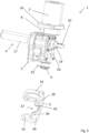
- figure 1 shows a perspective view of a drive 1 according to the invention for a flap, the drive 1 having a housing 2, a motor 3 and a spindle drive 4, the motor 3 and the spindle drive 4 being drive-connected to one another and enabling motorized adjustment of the flap, wherein the drive 1 moves the flap at least into an open position and a closed position.
- a holder 5, which accommodates the drive 1, is provided for fastening the drive 1 to or in a flap.
- an axis of rotation 6 of the motor 3 and an axis of rotation 7 of the spindle drive 4 arranged orthogonally to each other.
- the holder 5 enables the drive 1 to be pivoted, since the drive 1 is pivotably mounted in the holder by a first bearing point 8 and by a second bearing point 9 .
- the bearing points 8 , 9 are preferably plain bearings which are arranged between the housing 2 and the holder 5 .
- the drive 1 thus has a pivot axis 10 which runs parallel to the axis of rotation 6 of the motor 3 . This enables a pivoting movement of the drive 1 relative to the flap.
- connection point 20 is arranged at one end of the torque tube 16, which is connected to a vehicle body, wherein the torque tube 16 and the connection point 20 are firmly connected to one another in the axial direction and/or the torque tube 16 and the connection point 20 are connected to one another in a rotationally fixed manner.
- the connection point 20 can be designed in particular in the form of a ball joint or in the form of a through hole.
- the connection point 20 can also provide a torque support for the torque tube 16 .
- the connection point 20 can preferably be pivoted about a pivot axis 21 , the pivot axis 21 of the connection point 20 running parallel to the axis of rotation 6 of the motor 3 .
- FIG 2 shows a perspective view of the motor 3, the spindle drive 4 and the gear stages 11, 12.
- the motor 3 can be a brushless motor, for example.
- the gear stages 11, 12 consist of two gear stages 11, 12, the first gear stage 11 being a worm gear 11 and the second gear stage 12 being a spur gear 12.
- the first gear stage 11 is connected to the second gear stage 12 via an overload clutch 13 .
- the motor 3 can be connected to the first gear stage 11 via a flexible shaft 22 and/or an Oldham coupling is arranged between the motor 3 and the drive shaft 22 .
- a hysteresis brake 40 is arranged between the motor 3 and the spindle drive 4 .
- the axis of rotation 6 of the motor 3 can be braked, as a result of which the flap, in particular the vehicle door, can be held in all positions and vehicle positions.
- FIG 3 shows a section of the spindle drive 4 and a section of parts of the drive 1.
- the spindle drive 4 includes a threaded spindle 14 with a Nut 15 and a push tube 16, wherein the push tube 16 is connected via the nut 15 to the threaded spindle 14 and the push tube 16 is moved by a translational movement.
- the spindle drive 4 is arranged within a rotor 17 and the motor 3 drives the rotor 17 via the gear stages 11, 12, the rotor 17 being connected to the threaded spindle 14, in particular non-rotatably and having a hollow-cylindrical geometry.
- a gear 19 or a spur gear 19 is connected to the rotor 17, in particular connected in a rotationally fixed manner.
- the gear 19 of the rotor 17 is connected to the second gear stage 12 and is driven by it.
- the rotor 17 is connected to the threaded spindle 14 via an adapter 18, in particular non-rotatably connected.
- the adapter 18 is arranged on an end face of the rotor 17, the adapter 18 being connected to the rotor 17 in a positive and/or non-positive manner.
- the threaded spindle 14 is also positively and/or non-positively connected to the adapter 18, the threaded spindle 14 preferably having external teeth and the adapter 18 having corresponding internal teeth.
- the threaded spindle 14 rotates at the same rotational speed and speed as the rotor 17.
- the threaded spindle 14 can have a circumferential groove 24, which is arranged inside the adapter 18.
- a pin 25 which is connected to the adapter 18 can be arranged in the adapter 18 . This results in an additional positional locking of the threaded spindle 14.
- the threaded spindle 14 can have an axial lock.
- the threaded spindle 14 and the thrust tube 16 are surrounded radially by the rotor 17, with the thrust tube 16 being able to be moved out of the rotor 17 and the thrust tube 16 also being able to be moved back into the rotor 17.
- the rotor 17 is thus closed on one end, in particular by the adapter 18 and particularly preferably sealed watertight, and on the opposite end the rotor 17 has an opening from which at least the thrust tube 16 can protrude.
- the torque tube 16 can have an oval or polygonal geometry and a recess corresponding to the geometry of the torque tube 16 can be present in the housing 2 and/or in the holder 5. This prevents the recess in the housing and/or the holder, a twisting of the torque tube 16 and thus serves as a torque support.
- the connection point 20 can also provide a torque support for the torque tube 16 in that the connection point 20 has a fixed connection in the axial direction and/or a non-rotatable connection to the vehicle body, the connection point 20 with the vehicle body being orthogonal to the pivot axis 21 of the connection point 20 is fixed in the axial direction and/or is non-rotatable.
- a scanning disk 26 is arranged on the rotor 17 and is scanned by a sensor 27 arranged inside the housing 2 .
- the scanning disk 26 can be either magnetic or an optical scanning disk 26, the scanning disk 26 having a coding which can be scanned by the sensor 27 and a rotation angle can thereby be determined.
- the sensor 27 can determine the angle of rotation in absolute or relative terms.
- Two bearing points 39 are provided within the housing 2 for the bearing of the rotor 17 .
- FIG 4 shows a cut according to figure 3 with an additional guide tube 28.
- the guide tube 28 is arranged between the thrust tube 16 and the rotor 17.
- the spindle drive 4 consists of the threaded spindle 14 with the nut 15, the thrust tube 16 and the guide tube 28, with the guide tube 28 serving as a torque support for the thrust tube 16.
- the guide tube 28 is connected to a housing cover 29, in particular non-rotatably connected.
- the housing cover 29 closes an opening in the housing 2.
- the thrust tube 16 is thus connected to the threaded spindle 14 via the nut 15 or an internal thread.
- the rotational movement of the motor 3 can be converted into a translatory movement.
- the torque on the thrust tube 16 is supported on the guide tube 28 , which is connected to the housing 2 via the housing cover 29 in a torque-proof manner.
- the housing cover 29 and the guide tube 28 can also be designed in one piece.
- the nut 15 is preferably made of plastic.
- the nut 15 is advantageously made by injection through openings directly on the thrust tube 16 and fitted. This creates a stable and resistant connection between the push tube 16 and the nut 15 .
- the nut 15 has two holding extensions in the longitudinal direction, which are connected by a bridge and which engage in two openings in the thrust tube 16 which are one behind the other in the longitudinal direction. Thus, an optimal hold is guaranteed.
- the nut 15 is made of plastic.
- openings 30 are provided on the outer circumference for holding the nut 15 on the thrust tube.
- Four pairs of openings 30 distributed regularly over the circumference are advantageously provided, with the openings 30 of a pair lying one behind the other in the longitudinal direction of the thrust tube 16 .
- several openings 30 one behind the other in the longitudinal direction and associated holding projections 31 each connected via a bridge 32 can be provided, so that the holding forces per holding projection 31 are reduced and the risks of a possible breakage of an individual holding projection 31 can be prevented even more efficiently.
- only at least two, preferably four, openings 30 distributed regularly over the circumference can also be provided.
- a bridge 32 is formed between two retaining extensions 31 in that the nut 15 protrudes beyond an end face of the thrust tube 16 and this protrusion forms a first retaining extension 31 and the bridge 32 occurs between this protrusion of the nut 15 and the retaining extension 31, which is formed by the opening 30 protrudes.
- the bridges 32 Due to the retaining projections 31 and the bridges 32 connected thereto, which protrude beyond the thrust tube 16, the bridges 32 can engage in corresponding grooves in the guide tube 28 and the torque of the thrust tube 16 is supported as a result.
- a seal 41 is arranged between the thrust tube 16 and the housing 2 and between the rotor 17 and the housing 2 .
- figure 5 shows a perspective view of the holder 5 and the drive 1.
- the holder 5 encloses the housing 2 below the motor 3 and below the spindle drive 4 or in the axial direction of the first bearing point 8 on the opposite side of the spindle drive 4 2 a Extension 33 formed.
- the housing 2 has a cylindrical geometry. Furthermore, at least one bearing 8, 9 is arranged in each of these areas.
- the holder 5 has a U-shaped geometry in cross section, which consists of two receptacles 34 , 35 and the two receptacles 34 , 35 are connected to one another via a connecting web 36 .
- the holder 5 has a first hollow-cylindrical receptacle 34, which is preferably designed in two parts. Each part forms a semicircle. After the drive 1 has been inserted, the two parts can be connected to one another in a force-fitting, form-fitting and/or cohesive manner; in particular, the two parts can be screwed or welded. Below the spindle drive 4 or in the axial direction of the first bearing point 8 on the opposite side of the spindle drive 4, a second hollow-cylindrical receptacle 35 is arranged, into which the housing 2 is inserted.
- the connecting web 36 has a recess 37 for the push rod 16 and the connection point 20 .
- the dimensions of the recess 37 are contoured in such a way that the drive 1 can pivot.
- the recess 37 is a U-shaped recess 37 and is thus open to one side of the holder 5.
- This also allows the connecting web 36 to be constructed with a smaller width.
- a centering 42 can be arranged on the recess 37 by a protruding edge 42 being arranged on the outer peripheral edge of the recess 37 .
- At least two bores 38 are arranged on the connecting web 36, through which the holder 5 is screwed to the flap.
- at least one centering can be provided on the connecting web 36, which makes it easier to position the drive 1.
- the centering can be designed, for example, in the form of a cone, which is inserted into corresponding recesses in the flap.
- stud bolts can also be arranged on the connecting web 36 or stud bolts can be arranged on the holder 5 and the holder 5 is connected to the flap via the stud bolts tied together.
- the stud bolts provide both guidance and centering and no additional centering is necessary.
- a sensor which detects a swivel angle of the drive 1 can be arranged in the immediate vicinity of the drive 1 .
- a scanning disk is preferably arranged on the drive 1, which is scanned by the sensor and can thereby detect a pivoting angle of the drive 1.
- the scanning disk is preferably arranged on the motor 3 or on a housing of the motor 3 .
- the scanning disk is particularly preferably attached to a flange 43 of the motor 3 or the housing of the motor 3 and the sensor is arranged on the holder 5 .
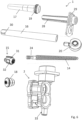
- figure 6 shows a perspective view of selected components of the drive 1.
- the rotor 17 is shown with the gear 19, the rotor 17 surrounding the thrust tube 16 and the threaded spindle 14 with nut 15 radially.
- a guide tube 28 can be arranged between the thrust tube 16 and the rotor 17 .
- the guide tube 28 is connected to the housing cover 29 and thus closes an opening in the housing 2.
- the openings 30 in the thrust tube 16 are also shown, as well as the nut 15 in detail, with the retaining extensions 31 and the bridge 32.
- the housing 2 and the adapter 18 shown.
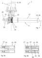
- FIG figure 7 shows a perspective view of a drive 1 according to the invention with only one gear stage 11, the drive 1 having a housing 2 (not shown), a motor 3 and a spindle drive 4, corresponding to FIG figure 1 .
- the motor 3 and the spindle drive 4 are connected to one another in terms of drive technology.
- a holder 5 (not shown) is provided, which holds the drive 1 .
- an axis of rotation 6 of the motor 3 and an axis of rotation 7 of the spindle drive 4 are arranged orthogonally to one another.
- connection point 20 is arranged at one end of the torque tube 16, which is connected to a vehicle body, wherein the torque tube 16 and the connection point 20 are firmly connected to one another in the axial direction and/or the torque tube 16 and the connection point 20 are connected to one another in a rotationally fixed manner.
- the connection point 20 can be designed in particular in the form of a ball joint or in the form of a through hole.
- the connection point 20 can also be a torque support provide for the thrust tube 16.
- the connection point 20 can preferably be pivoted about a pivot axis 21 , the pivot axis 21 of the connection point 20 running parallel to the axis of rotation 6 of the motor 3 .
- the motor 3 can be a brushless motor, for example.
- the gear stage 11 preferably consists of a worm gear 11.
- the gear stage 11 is connected to the gear 19 of the rotor 17 and is driven by it.
- the motor 3 can be connected to the first gear stage 11 via a flexible shaft 22 and/or an Oldham coupling is arranged between the motor 3 and the drive shaft 22 .
- a hysteresis brake 40 is arranged between the motor 3 and the spindle drive 4 .
- the axis of rotation 6 of the motor 3 can be braked, as a result of which the flap, in particular the vehicle door, can be held in all positions and vehicle positions.
- an overload clutch 13 is arranged on the rotor 17 .
- This consists of an adapter 44 which is connected to the rotor 17 in a fixed manner, in particular in a rotationally fixed manner.
- spring plates can be fixed in a non-rotatable, form-fitting manner.
- the spring plates are mounted on the threaded spindle 14 with a defined preload and the adapter 44 is mounted on the threaded spindle 14 so that it can rotate.
- a locking ring can be provided on the adapter 44, which prevents axial displacement between the threaded spindle 14 and the adapter 44. If a certain torque is exceeded or if a peak load acts on the system, the spring plates and the threaded spindle 14 can slip against one another.
- the adapter 44 has a receiving bore for the dowel pin.
- the adapter 44 can be made in one piece from hardened steel or from plastic with a hardened insert.
- One side of the dowel pin is pressed into the mounting hole of the adapter 44.
- the opposite side of the dowel pin is pressed into a receiving bore of the threaded spindle 14.
- a torque can thereby be transmitted from the adapter 44 to the threaded spindle 14 via the dowel pin. This is done via the frictional connection between the adapter 44 and the dowel pin and via the frictional connection between the threaded spindle 14 and the dowel pin.
- an axial bearing can be provided on the threaded spindle 14 .
- An axial lock can be implemented using lock washers, which are arranged between the adapter 44 and the threaded spindle 14 .
- the adapter 44 is held non-rotatably on the rotor 17 in a force-fitting, form-fitting and/or cohesive manner.
- Figure 8a shows an overload clutch 13 within the adapter 44 with spring plates, not shown.
- Figure 8b shows an overload clutch 13 within the adapter 44 with a dowel pin 45.
- One side of the dowel pin 45 is pressed into a receiving bore 46 of the adapter 44 and the opposite side of the dowel pin 45 is in a receiving bore 47 of another adapter 48, which has a non-positive and/or or positive connection with the threaded spindle 14 is pressed.
- a receiving bore can also be arranged in the threaded spindle 14 . Then the additional adapter 48 is not necessary.
- Figure 8c shows an overload clutch 13 with an adapter 44.
- the threaded spindle 14 protrudes through the adapter 44 from the rotor 17.
- the threaded spindle 14 has a dowel pin 45 in the rear area, which is arranged between the threaded spindle 14 and the adapter 44 .
- the clamping pin 45 is fixed in the axial direction by a pin 59 which projects through a bore in the threaded spindle 14 .
- the threaded spindle 14 is prestressed by a spring arrangement 49 and this reduces the play of the threaded spindle 14 or the dowel pin 45 in the axial direction.
- the spring arrangement 49 is thus supported on one side on the adapter 44 and on the opposite side on the axial securing element 50.
- Figure 8d shows an overload clutch 13 within the adapter 44 with a roll pin 45.
- the threaded spindle 14 has a roll pin 45 in the rear region, which is arranged between the threaded spindle 14 and the adapter 44.
- the clamping pin 45 is fixed in the axial direction by a pin 59 which projects through a bore in the threaded spindle 14 .
- Figure 8e shows like that Figure 8c an overload clutch 13 with an adapter 44.
- a cone 52 is arranged inside the adapter 44 , one end of the cone protruding from the rotor 17 via the adapter 44 .
- the cone 52 is prestressed by a spring arrangement 49 and is thereby connected to the adapter 44 in a rotationally fixed manner.
- a groove is arranged on the cone 52, in which an axial securing element 50, in particular a securing ring, is arranged.
- the spring arrangement 49 is thus supported on one side on the adapter 44 and on the opposite side on the axial securing element 50.
- the overload clutch 13 can be triggered by different spring constants of the spring arrangement 49 and/or different diameters of the cone and/or the conicity be adjusted.
- the cone 52 can be connected to the threaded spindle 14 in a non-positive and/or positive manner.
- Figure 8f shows an overload clutch 13 within the adapter 44 with a tolerance ring 53 as an overload clutch 13.
- the tolerance ring 53 is arranged between the adapter 44 and another adapter 48.
- the tolerance ring 53 can be arranged between the adapter 44 and the threaded spindle 14 .
- the additional adapter 48 can be dispensed with.
- the tolerance ring 53 connects the adapter 44 to the other adapter 48 or to the threaded spindle 14 and transmits a defined torque. As soon as the defined torque is exceeded, the tolerance ring 53 allows the adapter or the threaded spindle to rotate relative to one another.
- the tolerance ring 53 preferably consists of a stamped strip of metal which is rolled into an open sleeve and formed or stamped with, for example, corrugations or fingers along the outside and/or the inside are.
- the tolerance ring 53 preferably has a lateral gap which predetermines the prestressing of the tolerance ring 53 .
- the adapter 44 particularly preferably has a steel insert at least in the area of the tolerance ring 53 .
- the adapter 44 can be made of a plastic, for example.
- figure 9 shows a section of the drive 1, according to figure 7 , with a sensor 27 for determining the angle of rotation of the threaded spindle 14.
- the sensor 27 can be an incremental sensor 27 and the scanning disk 26 or coding 26 can be a magnetic disk 26, which is connected to the threaded spindle 14 in a fixed or non-rotatable manner.
- the sensor 27 is preferably attached at a distance from the thrust tube 16 and is connected to electronics 54 which are attached to or in the housing 2 .
- the connection between the sensor 27 and the electronics 54 can be made by cables or a flexible printed circuit board.
- the material of the thrust tube 16 is preferably not ferromagnetic, so that it is not possible to shield a magnetic field.
- the sensor 27 is preferably attached to or in the housing 2 .
- the sensor 27 can detect the polarity change of the magnetic disk 26 and thus determine the angle of rotation of the threaded spindle 14 .
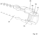
- figure 10 shows a section of a part of the threaded spindle 14 and the scanning disk 26.
- a corrugation 55 is preferably arranged on the threaded spindle 14 at least in the region of the scanning disk 26.
- the scanning disk 26 can be connected to the threaded spindle 14 via a carrier 56 .
- the scanning disk 26 is glued to the carrier 56, for example, and then fastened to the threaded spindle 14, preferably in a non-positive and/or positive manner.
- a groove 57 can be arranged on the threaded spindle, in which a nose 58 of the carrier 56 engages and/or a locking washer can be arranged in front of the carrier 56, which holds the carrier 56 and the scanning disk 26 in position holds.
Landscapes
- Engineering & Computer Science (AREA)
- General Engineering & Computer Science (AREA)
- Mechanical Engineering (AREA)
- Connection Of Motors, Electrical Generators, Mechanical Devices, And The Like (AREA)
- Blow-Moulding Or Thermoforming Of Plastics Or The Like (AREA)
Abstract
Description
- Die Erfindung betrifft einen Antrieb für eine Klappe, wobei der Antrieb ein Gehäuse, einen Motor und einen Spindelantrieb aufweist, wobei der Motor und der Spindelantrieb antriebstechnisch miteinander verbunden sind und eine motorische Verstellung der Klappe ermöglichen, wobei der Antrieb die Klappe mindestens in eine geöffnete Position und eine geschlossene Position verfährt, wobei der Spindelantrieb eine Gewindespindel mit einer Mutter und ein Schubrohr aufweist und das Schubrohr über die Mutter mit der Gewindespindel verbunden ist, wobei das Schubrohr durch eine translatorische Bewegung verfahren wird.
- Der erfindungsgemäße Antrieb kann zur Verstellung von einer Vielzahl von unterschiedlichen Klappen eines Fahrzeugs genutzt werden. So ist unter den Begriff Klappe sowohl eine Heckklappe, eine Kofferraumklappe oder eine Motorhaube zu verstehen, als auch eine Seitentür, eine Schiebetür oder ein Laderaumboden.
- Aus dem Stand der Technik sind entsprechenden Antriebe für Klappen bekannt. Beispielsweise offenbart die
DE 10 2018 117 413 A1 einen entsprechenden Antrieb mit einem Spindel-Spindelmuttergetriebe. Der Antrieb ist schwenkbar an einer Klappe angeordnet und schwenkbar mit einer Fahrzeugkarosserie verbunden. - Nachteilig an diesem Antrieb ist der große Bauraumbedarf, da diese Art von Antrieben auch in Seitentüren eingebaut werden, in welchen sehr beengte Platzverhältnisse vorherrschen und sehr hohe Anforderungen an die Antriebe gestellt werden, insbesondere an deren optischen Erscheinung, der akustischen Wahrnehmbarkeit und der Abdichtung der Antriebe gegenüber Umwelteinflüssen, wie beispielsweise in die Tür eintretendes Wasser.
- Es ist daher die Aufgabe der Erfindung, die bekannten Nachteile zu beseitigen und auf diese Weise die bekannten Antriebe verbessern.
- Diese Aufgabe wird bei einem Antrieb der eingangs genannten Art dadurch erreicht, dass der Spindelantrieb innerhalb eines Rotors angeordnet ist und der Motor den Rotor antreibt, wobei der Rotor mit der Gewindespindel verbunden ist, insbesondere ist der Rotor mit der Gewindespindel drehfest verbunden. Vorzugsweise ist der Rotor mit der Gewindespindel über einen Adapter verbunden, insbesondere ist der Rotor mit der Gewindespindel über den Adapter drehfest verbunden. Hierzu kann der Rotor eine hohlzylindrische Geometrie aufweisen. Dadurch sind die Gewindespindel und das Schubrohr radial von dem Rotor umgeben, wobei das Schubrohr aus dem Rotor verfahren werden kann und das Schubrohr auch wieder in den Rotor hinein verfahren werden kann. Somit ist der Rotor auf einer Stirnseite verschlossen, insbesondere wasserdicht verschlossen und auf der gegenüberliegenden Stirnseite weißt der Rotor eine Öffnung auf, aus welcher mindestens das Schubrohr herausragen kann.
- In einer weiteren Ausgestaltung kann der Spindelantrieb mindestens teilweise aus dem Gehäuse herausragen. Dadurch weist das Gehäuse in Richtung des Spindelantriebs kleinere Abmessungen auf, wodurch das Gehäuse einen geringeren Bauraum beansprucht.
- In einer weiteren Ausgestaltung ist zwischen dem Gehäuse und dem Rotor mindestens ein Lager angeordnet. Dadurch ist der Rotor drehbar im Gehäuse angeordnet und kann sich unabhängig von dem Gehäuse drehen.
- In einerweiteren Ausgestaltung ist ein Zahnrad bzw. ein Stirnrad mit dem Rotor verbunden, insbesondere ist das Zahnrad bzw. das Stirnrad drehfest mit dem Rotor verbunden. Vorzugsweise sind das Zahnrad bzw. das Stirnrad und der Rotor einteilig ausgebildet. Aufgrund dieses Zahnrads kann die Drehbewegung des Motors auf den Rotor übertragen werden. Vorzugsweise sind dazu die Motorausgangswelle sowie das Zahnrad des Rotors innerhalb des Gehäuses angeordnet.
- In einer weiteren Ausgestaltung sind der Motor und der Spindelantrieb über eine erste Getriebestufe, insbesondere ein Schneckenradgetriebe, antriebstechnisch verbunden, wobei die erste Getriebestufe den Rotor antreibt. Insbesondere treibt der Motor über die erste Getriebestufe, insbesondere dem Schneckenradgetriebe, eine zweite Getriebestufe, insbesondere ein Stirnradgetriebe, an, welches wiederrum den Rotor antreibt. Somit überträgt das Stirnrad das Drehmoment auf das Zahnrad bzw. auf das Stirnrad des Rotors, welches radial und axial fest, insbesondere drehfest mit dem Rotor verbunden ist. Mit anderen Worten treibt der Motor über mindestens eine Getriebestufe, bevorzugt über zwei Getriebestufen, den Rotor an. Der Adapter ist mit dem Rotor verbunden, insbesondere drehfest verbunden und überträgt das Drehmoment vom Rotor auf die Gewindespindel. Vorzugsweise sind der Adapter und der Rotor einteilig ausgebildet. Der Rotor und die Gewindespindel sind fest miteinander verbunden. Somit kommt es zu einer Drehbewegung der Spindel.
- Bevorzugt ist zwischen dem Motor und der ersten Getriebestufe, insbesondere dem Schneckenradgetriebe, eine Oldham-Kupplung und/oder eine flexible Welle angeordnet. Dadurch kann ein Versatz zwischen der Motorausgangswelle und der ersten Getriebestufe ausgeglichen werden. Alternativ kann zwischen dem Motor und der ersten Getriebestufe, insbesondere dem Schneckenradgetriebe, eine starre Welle angeordnet sein
- Weiterhin sind die erste Getriebestufe, insbesondere das Schneckenradgetriebe und die zweite Getriebestufe, insbesondere das Stirnradgetriebe, mittels einer Überlastkupplung verbunden. Im Falle einer Fehlbedienung, zum Beispiel durch abruptes Anziehen an der Fahrzeugtür entgegen der elektrischen Öffnung- oder Schließbewegung, wird der Kraftfluss zwischen dem Schneckenradgetriebe und dem Stirnradgetriebe unterbrochen. Dadurch können das Stirnrad und das Schneckenrad gegeneinander durchrutschen und die Fehlbedienung führt nicht zu einer Zerstörung des Antriebs, insbesondere des Stirnrads oder des Schneckenrads.
- Alternativ kann bei der Verwendung nur einer Getriebestufe, insbesondere ein Schneckenradgetriebe, welche den Motor mit dem Spindelantrieb antriebstechnisch verbindet, eine Überlastkupplung am Rotor angeordnet sein. Aufgrund dieser Ausgestaltung, mit nur einer Getriebestufe, können die Abmessungen des Antriebs weiter verringert werden. Dazu kann ein Adapter mit dem Rotor fest verbunden sein. In dem Adapter können beispielsweise Federbleche drehfest formschlüssig fixiert sein. Die Federbleche sind auf der Gewindespindel mit einer definierten Vorspannung montiert und der Adapter ist drehbar auf der Gewindespindel montiert. Zusätzlich kann ein Sicherungsring an dem Adapter vorgesehen sein, welcher eine Axialverschiebung zwischen der Gewindespindel und dem Adapter verhindert. Bei einer Überschreitung eines bestimmten Drehmoments oder bei der Einwirkung einer Lastspitze auf das System, können die Federbleche und die Gewindespindel gegeneinander durchrutschen.
- Weiterhin ist es auch möglich, dass anstatt von Federblechen ein Spannstift als Überlastkupplung dient. Dazu ist in dem Adapter eine Aufnahmebohrung für den Spannstift eingebracht. Der Adapter kann einteilig aus gehärtetem Stahl oder aus Kunststoff mit einem gehärteten Einlegeteil ausgeführt sein. In die Aufnahmebohrung des Adapters wird der Spannstift mit einer Seite eingepresst. Die andere Seite des Spannstiftes wird in eine Aufnahmebohrung der Gewindespindel eingepresst. Dadurch kann ein Drehmoment vom Adapter über den Spannstift auf die Gewindespindel übertragen werden. Dies geschieht über den Reibschluss zwischen dem Adapter und dem Spannstift sowie über den Reibschluss zwischen der Gewindespindel und dem Spannstift. Bei einer Überschreitung eines bestimmten Drehmoments oder bei der Einwirkung einer Lastspitze auf das System, können der Adapter, der Spannstift und/oder die Gewindespindel gegeneinander durchrutschen. Um die Reibung in axialer Richtung zu minimieren kann ein Axiallager auf der Gewindespindel vorgesehen sein. Eine Axialsicherung kann über Sicherungsscheiben, welche zwischen dem Adapter und der Gewindespindel angeordnet sind, realisiert werden. In einer weiteren Ausgestaltung weist der Spindelantrieb zusätzlich ein Führungsrohr auf, worüber eine Drehmomentabstützung des Schubrohrs erfolgt. Dazu kann das Führungsrohr mit einem Gehäusedeckel verbunden sein, insbesondere drehfest verbunden sein. Vorzugsweise können das Führungsrohr und der Gehäusedeckel einteilig ausgebildet sein. Der Gehäusedeckel verschließt dabei eine Öffnung im Gehäuse. Somit ist das Schubrohr mit der Gewindespindel über die Mutter bzw. ein Innengewinde verbunden. Dadurch kann die Drehbewegung des Motors in eine translatorische Bewegung umgewandelt werden. Um dies zu ermöglichen wird das Drehmoment an dem Schubrohr am Führungsrohr, welches drehfest mit dem Gehäuse über den Gehäusedeckel verbunden ist, abgestützt. Der Gehäusedeckel und das Führungsrohr können dabei auch einteilig ausgebildet sein.
- In einer weiteren Ausgestaltung ist an einem Ende des Schubrohrs eine Anbindungsstelle angeordnet, welche mit einer Fahrzeugkarosserie verbunden wird, wobei das Schubrohr und die Anbindungsstelle miteinander verbunden sind, insbesondere sind das Schubrohr und die Anbindungsstelle in axialer Richtung fest verbunden und/oder das Schubrohr und die Anbindungsstelle sind drehfest verbunden. Die Anbindungsstelle kann dabei insbesondere in Form eines Kugelgelenks oder in Form einer Durchgangsbohrung ausgebildet sein. Weiterhin kann die Verbindungstelle auch eine Drehmomentabstützung für das Schubrohr bereitstellen. Vorzugsweise ist die Anbindungsstelle um eine Schwenkachse schwenkbar, wobei die Schwenkachse der Anbindungsstelle parallel zur Drehachse des Motors verläuft. Alternativ kann die Schwenkachse der Anbindungsstelle und die Drehachse des Motors genau einen Schnittpunkt aufweisen. Somit können die Schwenkachse der Anbindungsstelle und die Drehachse des Motors winklig zueinander angeordnet sein.
- In einer weiteren Ausgestaltung ist der Antrieb über einen Halter an der Klappe befestigt. Bevorzugt ist das Gehäuse in dem Halter über mindestens zwei Lagerstellen gehalten, wobei eine Lagerstelle in der Nähe des Motors angeordnet sein kann, insbesondere zwischen dem Motor und dem Spindelantrieb und eine weitere Lagerstelle in axialer Richtung der ersten Lagerstelle auf der gegenüberliegenden Seite des Spindelantriebs. Weiterhin kann der Halter eine im Querschnitt U-förmige Geometrie aufweisen. Dadurch ist das Gehäuse schwenkbar im Halter gelagert und der Halter wird fest mit der Klappe verschraubt, insbesondere innerhalb einer Tür mit dieser verschraubt.
- In einer weiteren Ausgestaltung sind eine Drehachse des Motors und eine Drehachse des Spindelantriebs windschief zueinander angeordnet. Somit sind die Drehachse des Motors und die Drehachse des Spindelantriebs nicht parallel zueinander und weisen einen Winkeln größer 0° zueinander auf. Bevorzugt sind die Drehachse des Motors und die Drehachse des Spindelantriebs in einem Winkel zwischen 30° und 90° zueinander angeordnet, besonders bevorzugt sind die Drehachse des Motors und die Drehachse des Spindelantriebs orthogonal zueinander angeordnet. Alternativ können die Drehachse des Motors und die Drehachse des Spindelantriebs genau einen Schnittpunkt aufweisen. Weiterhin kann der Antrieb um eine Schwenkachse schwenkbar gelagert sein, wobei vorzugsweise die Schwenkachse parallel zu der Drehachse des Motors verläuft. Dadurch wird eine Schwenkbewegung des Antriebs relativ zur Klappe ermöglicht. Alternativ kann entsprechend der Einbaubedingungen die Schwenkachse windschief zu der Drehachse des Motors verlaufen oder die Schwenkachse und die Drehachse des Motors weisen genau einen Schnittpunkt auf.
- In einer weiteren Ausgestaltung ist an dem Rotor eine Abtastscheibe angeordnet, welche von einem Sensor, der innerhalb des Gehäuses angeordnet ist, abgetastet wird. Dabei kann die Abtastscheibe sowohl magnetisch sein als auch eine optische Abtastscheibe, wobei die Abtastscheibe eine Codierung aufweist, welche von dem Sensor abgetastet werden kann und dadurch ein Drehwinkel bestimmt werden kann. Somit ist an dem Rotor ein Drehgeber angeordnet. Dabei kann der Sensor den Drehwinkel absolut oder relativ bestimmen. Besonders bevorzugt wird ein Inkrementaldrehgeber verwendet.
- Alternativ kann zur Bestimmung des Drehwinkels beispielsweise ein Sensor, insbesondere ein Inkrementalsensor, vorgesehen sein, wobei die Abtastscheibe bzw. Codierung, insbesondere eine Magnetscheibe, fest mit der Gewindespindel verbunden ist. Das Material des Schubrohrs ist bevorzugt nicht ferromagnetisch, so dass keine Abschirmung eines Magnetfelds möglich ist. Der Sensor ist dabei bevorzugt an bzw. in dem Gehäuse befestigt. Der Inkrementalsensor kann die Polwechsel der Magnetscheibe erfassen und so den Drehwinkel der Gewindespindel bestimmen. In einer weiteren Ausgestaltung ist mindestens jeweils eine Abdichtung zwischen dem Schubrohr und dem Gehäuse und zwischen dem Rotor und dem Gehäuse angeordnet. Dabei kann die Abdichtung des Schubrohrs zusätzlich einen Abstreifer bzw. einen abstreifenden Effekt aufweisen, so dass mögliche Verunreinigungen nicht in das Gehäuse eindringen können. Weiterhin wird dadurch eine Verschmutzung der Funktionsflächen der Gewindespindel ausgeschlossen und der Antrieb ist geschützt vor eindringen Wasser oder Verunreinigungen.
- In einer weiteren Ausgestaltung kann zwischen dem Motor und dem Spindelantrieb eine Hysteresebremse angeordnet sein. Aufgrund der Hysteresebremse kann die Drehachse des Motors gebremst werden, wodurch ein Halten der Klappe, insbesondere der Fahrzeugtür, in allen Positionen und Fahrzeuglagen erfolgen kann.
- In einer weiteren Ausgestaltung kann in unmittelbarer Nähe zu dem Antrieb oder an dem Antrieb bzw. an oder in dem Gehäuse des Antriebs ein Sensor angeordnet sein, welcher einen Schwenkwinkel des Antriebs detektiert. Vorzugsweise ist an dem Antrieb eine Codierung angeordnet, welche von dem Sensor abgetastet wird und dadurch einen Schwenkwinkel des Antriebs detektieren kann. Vorzugsweise ist die Codierung an dem Motor oder an einem Gehäuse des Motors angeordnet, insbesondere erstreckt sich die Codierung mindestens teilweise über den Außenumfangs des Motors oder des Gehäuses des Motors. Somit kann sich die Codierung nur über den Bereich des Motors oder des Gehäuses des Motors erstrecken, welcher dem maximalen Schwenkwinkel des Antriebs entspricht. Insbesondere ist der Sensor an dem Halter angeordnet. Die Codierung kann dabei beispielsweise auf einer Codescheibe oder Abtastscheibe aufgebracht werden, welche an dem Motor oder an dem Gehäuse des Motors angeordnet ist oder direkt an dem Motor bzw. an dem Gehäuse des Motors aufgebracht werden. Weiterhin kann die Codierung beispielsweise in Form einer Verzahnung an dem Motor oder dem Gehäuse des Motors angeordnet sein, insbesondere können die Verzahnung und das Gehäuse des Motors einteilig ausgebildet sein. Der Sensor kann ein Magnetsensor, ein optischer Sensor, ein induktiver Sensor oder ein kapazitiver Sensor sein. Entsprechend des Funktionsprinzips des Sensors ist auch die Codierung ausgebildet.
- Alternativ kann die Codierung auch an dem Halter angeordnet sein und der Sensor an oder in dem Gehäuse des Motors angeordnet sein.
- Bevorzugt handelt es sich um einen Inkrementalsensor, bei dem die Markierungen bzw. Codierungen gezählt werden oder um einen Absolutsensor, welcher eine Codierung aufweist, die eindeutig den Schwenkwinkel definiert. Dadurch kann eine absolute Position des Antriebs bestimmt werden und diese mit der Position des Spindelantriebs verglichen werden. Beispielsweise kann nach einem Stromausfall dadurch die Position des Spindelantriebs bestimmt werden ohne dass eine Referenzfahrt des Spindelantriebs notwendig ist.
- Weiterhin kann ein Magnet an dem Halter angeordnet sein, welcher sich über einen im Gehäuse untergebrachten Sensor bewegt, wobei der Sensor beispielsweise ein 2D oder 3D Hallsensor sein kann.
- Aufgrund des Sensors und der Codierung kann der aktuelle Schwenkwinkel des Antriebs und somit auch der aktuelle Schwenkwinkel der Klappe detektiert werden. Dadurch kann unter Zuhilfenahme weiterer Sensoren beispielsweise eine Hinderniserkennung und eine unbeabsichtigte Türbewegung erkannt werden. Beispielsweise kann für eine Hinderniserkennung der Schwenkwinkel und ein Drehmoment des Antriebs bestimmt werden und sobald das Drehmoment einen Grenzwert übersteigt kann das verschwenken der Klappe unterbrochen werden.
- Weitere Merkmale und Vorteile der Erfindung ergeben sich aus der nachfolgenden Beschreibung sowie aus den beigefügten Zeichnungen, auf die im Folgenden Bezug genommen wird. In den Zeichnungen zeigen:
-
Figur 1 eine perspektivische Ansicht eines erfindungsgemäßen Antrieb, -
Figur 2 eine perspektivische Ansicht des Motors, des Spindelantriebs und des Getriebes, -
Figur 3 einen Schnitt des Spindelantriebs sowie von Teilen des Antriebs, -
Figur 4 einen Schnitt gemäßFigur 3 mit einem zusätzlichen Führungsrohr, -
Figur 5 eine perspektivische Ansicht des Halters und des Antriebs -
Figur 6 eine perspektivische Ansicht von ausgewählten Bauteilen des Antrieb -
Figur 7 eine perspektivische Ansicht eines erfindungsgemäßen Antriebs mit einer Getriebestufe -
Figur 8 a - f zeigen jeweils einen Schnitt durch einen Teil des Antriebs ausFigur 7 mit verschiedenen Ausgestaltungen der Überlastkupplung -
Figur 9 eine Schnittansicht des Antriebs ausFigur 7 -
Figur 10 einen Teil einer Gewindespindel mit einer Abtastscheibe gemäßFigur 9 -
Figur 1 zeigt eine perspektivische Ansicht eines erfindungsgemäßen Antrieb 1 für eine Klappe, wobei der Antrieb 1 ein Gehäuse 2, einen Motor 3 und einen Spindelantrieb 4 aufweist, wobei der Motor 3 und der Spindelantrieb 4 antriebstechnisch miteinander verbunden sind und eine motorische Verstellung der Klappe ermöglichen, wobei der Antrieb 1 die Klappe mindestens in eine geöffnete Position und eine geschlossene Position verfährt. Zur Befestigung des Antriebs 1 an oder in einer Klappe ist ein Halter 5 vorgesehen, welcher den Antrieb 1 aufnimmt. Weiterhin sind eine Drehachse 6 des Motors 3 und eine Drehachse 7 des Spindelantriebs 4 orthogonal zueinander angeordnet. Der Halter 5 ermöglicht ein verschwenken des Antriebs 1, da der Antrieb 1 durch eine erste Lagerstelle 8 und durch eine zweite Lagerstelle 9 in dem Halter schwenkbar gelagert ist. Vorzugsweise handelt es sich bei den Lagerstellen 8, 9, um Gleitlager, welche zwischen dem Gehäuse 2 und dem Halter 5 angeordnet sind. Somit weist der Antrieb 1 eine Schwenkachse 10 auf, welche parallel zu der Drehachse 6 des Motors 3 verläuft. Dadurch wird eine Schwenkbewegung des Antriebs 1 relativ zur Klappe ermöglicht. - Weiterhin ist an einem Ende des Schubrohrs 16 eine Anbindungsstelle 20 angeordnet, welche mit einer Fahrzeugkarosserie verbunden wird, wobei das Schubrohr 16 und die Anbindungsstelle 20 in axialer Richtung fest miteinander verbunden sind und/oder das Schubrohr 16 und die Anbindungsstelle 20 drehfest miteinander verbunden sind. Die Anbindungsstelle 20 kann dabei insbesondere in Form eines Kugelgelenks oder in Form einer Durchgangsbohrung ausgebildet sein. Weiterhin kann die Verbindungstelle 20 auch eine Drehmomentabstützung für das Schubrohr 16 bereitstellen. Vorzugsweise ist die Anbindungsstelle 20 um eine Schwenkachse 21 schwenkbar, wobei die Schwenkachse 21 der Anbindungsstelle 20 parallel zur Drehachse 6 des Motors 3 verläuft.
-
Figur 2 zeigt eine perspektivische Ansicht des Motors 3, des Spindelantriebs 4 und der Getriebestufen 11, 12. Der Motor 3 kann beispielsweise ein bürstenloser Motor sein. Die Getriebestufen 11, 12, bestehen aus zwei Getriebestufen 11, 12, wobei die erste Getriebestufe 11 ein Schneckenradgetriebe 11 ist und die zweite Getriebestufe 12 ein Stirnradgetriebe 12 ist. Die erste Getriebestufe 11 ist mit der zweiten Getriebestufe 12 über eine Überlastkupplung 13 verbunden. Der Motor 3 kann mit der ersten Getriebestufe 11 über eine flexible Welle 22 verbunden sein und/oder zwischen dem Motor 3 und der Antriebswelle 22 ist eine Oldham Kupplung angeordnet. - Des Weiteren ist zwischen dem Motor 3 und dem Spindelantrieb 4 eine Hysteresebremse 40 angeordnet. Dadurch kann die Drehachse 6 des Motors 3 gebremst werden, wodurch ein Halten der Klappe, insbesondere der Fahrzeugtür, in allen Positionen und Fahrzeuglagen erfolgen kann.
-
Figur 3 zeigt einen Schnitt des Spindelantriebs 4 sowie einen Schnitt von Teilen des Antriebs 1. Der Spindelantrieb 4 umfasst eine Gewindespindel 14 mit einer Mutter 15 und einem Schubrohr 16, wobei das Schubrohr 16 über die Mutter 15 mit der Gewindespindel 14 verbunden ist und das Schubrohr 16 durch eine translatorische Bewegung verfahren wird. Der Spindelantrieb 4 ist innerhalb eines Rotors 17 angeordnet und der Motor 3 treibt den Rotor 17 über die Getriebestufen 11, 12 an, wobei der Rotor 17 mit der Gewindespindel 14 verbunden ist, insbesondere drehfest und eine hohlzylindrische Geometrie aufweist. Dazu ist mit dem Rotor 17 ein Zahnrad 19 bzw. ein Stirnrad 19 verbunden, insbesondere drehfest verbunden. Das Zahnrad 19 des Rotors 17 ist mit der zweiten Getriebestufe 12 verbunden und wird durch diese angetrieben. - Weiterhin ist der Rotor 17 mit der Gewindespindel 14 über einen Adapter 18 verbunden, insbesondere drehfest verbunden. Der Adapter 18 ist an einer Stirnseite des Rotors 17 angeordnet, wobei der Adapter 18 mit dem Rotor 17 formschlüssig und/oder kraftschlüssig verbunden ist. Die Gewindespindel 14 ist mit dem Adapter 18 ebenfalls formschlüssig und/oder kraftschlüssig verbunden, wobei die Gewindespindel 14 bevorzugt eine Außenverzahnung aufweist und der Adapter 18 eine entsprechende Innenverzahnung. Dadurch dreht sich die Gewindespindel 14 mit derselben Drehzahl und Geschwindigkeit wie der Rotor 17. Zusätzlich kann die Gewindespindel 14 eine umlaufende Nut 24 aufweisen, welche innerhalb des Adapters 18 angeordnet ist. Dazu kann in dem Adapter 18 ein Stift 25 angeordnet sein, welcher mit dem Adapter 18 verbunden ist. Dadurch erfolgt eine zusätzliche Lagesicherung der Gewindespindel 14. Alternativ kann die Gewindespindel 14 eine Axialsicherung aufweisen.
- Die Gewindespindel 14 und das Schubrohr 16 sind radial von dem Rotor 17 umgeben, wobei das Schubrohr 16 aus dem Rotor 17 verfahren werden kann und das Schubrohr 16 auch wieder in den Rotor 17 hinein verfahren werden kann. Somit ist der Rotor 17 auf einer Stirnseite verschlossen, insbesondere durch den Adapter 18 und besonders bevorzugt wasserdicht verschlossen und auf der gegenüberliegenden Stirnseite weißt der Rotor 17 eine Öffnung auf, aus welcher mindestens das Schubrohr 16 herausragen kann.
- Um eine Drehmomentabstützung des Schubrohrs 16 zu gewährleisten kann das Schubrohr 16 eine ovale oder mehreckige Geometrie aufweisen und im Gehäuse 2 und/oder in dem Halter 5 kann eine der Geometrie des Schubrohrs 16 entsprechende Aussparung vorhanden sein. Dadurch verhindert die Aussparung in dem Gehäuse und/oder dem Halter eine Verdrehung des Schubrohrs 16 und dient somit als eine Drehmomentabstützung. Des Weiteren kann die Verbindungstelle 20 auch eine Drehmomentabstützung für das Schubrohr 16 bereitstellen, indem die Verbindungstelle 20 eine in axialer Richtung feste Verbindung und/oder eine drehfeste Verbindung zu der Fahrzeugkarosserie aufweist, wobei die Verbindungstelle 20 mit der Fahrzeugkarosserie orthogonal zu der Schwenkachse 21 der Anbindungsstelle 20 in axialer Richtung fest ausgebildet ist und/oder drehfest ausgebildet ist.
- Weiterhin ist an dem Rotor 17 eine Abtastscheibe 26 angeordnet, welche von einem Sensor 27, der innerhalb des Gehäuses 2 angeordnet ist, abgetastet wird. Die Abtastscheibe 26 kann sowohl magnetisch sein als auch eine optische Abtastscheibe 26 sein, wobei die Abtastscheibe 26 eine Codierung aufweist, welche von dem Sensor 27 abgetastet werden kann und dadurch ein Drehwinkel bestimmt werden kann. Der Sensor 27 kann den Drehwinkel absolut oder relativ bestimmen.
- Für die Lagerung des Rotors 17 sind innerhalb des Gehäuses 2 zwei Lagerstellen 39 vorgesehen.
-
Figur 4 zeigt einen Schnitt gemäßFigur 3 mit einem zusätzlichen Führungsrohr 28. Das Führungsrohr 28 ist zwischen dem Schubrohr 16 und dem Rotor 17 angeordnet. Somit besteht der Spindelantrieb 4 in diesem Ausführungsbeispiel aus der Gewindespindel 14 mit der Mutter 15, dem Schubrohr 16 und dem Führungsrohr 28, wobei das Führungsrohr 28 als Drehmomentabstützung für das Schubrohr 16 dient. Dazu ist das Führungsrohr 28 mit einem Gehäusedeckel 29 verbunden, insbesondre drehfest verbunden. Der Gehäusedeckel 29 verschließt dabei eine Öffnung im Gehäuse 2. Somit ist das Schubrohr 16 mit der Gewindespindel 14 über die Mutter 15 bzw. ein Innengewinde verbunden. Dadurch kann die Drehbewegung des Motors 3 in eine translatorische Bewegung umgewandelt werden. Um dies zu ermöglichen wird das Drehmoment an dem Schubrohr 16 am Führungsrohr 28, welches drehfest mit dem Gehäuse 2 über den Gehäusedeckel 29 verbunden ist, abgestützt. Der Gehäusedeckel 29 und das Führungsrohr 28 können dabei auch einteilig ausgebildet sein. - Vorzugsweise ist die Mutter 15 aus Kunststoff gefertigt. Vorteilhaft wird die Mutter 15 durch Einspritzen durch Öffnungen direkt am Schubrohr 16 gefertigt und eingepasst. Dadurch wird eine stabile und widerstandfähige Verbindung zwischen dem Schubrohr 16 und der Mutter 15 hergestellt. Vorteilhafterweise besitzt die Mutter 15 in Längsrichtung jeweils zwei, über eine Brücke verbundene Haltefortsätze, die in zwei, in Längsrichtung hintereinander liegende Öffnungen im Schubrohr 16 eingreifen. Somit ist ein optimaler Halt gewährt.
- Erfindungsgemäß ist die Mutter 15 aus Kunststoff gefertigt. Am Schubrohr 16 sind zur Halterung der Mutter 15 am Schubrohr 16 Öffnungen 30 am Außenumfang vorgesehen. Vorteilhafterweise sind vier, regelmäßig über den Umfang verteilte Paare von Öffnungen 30 vorgesehen, wobei die Öffnungen 30 eines Paares in Längsrichtung des Schubrohres 16 hintereinander liegen. Alternativ können auch mehrere in Längsrichtung hintereinander liegende Öffnungen 30 und zugeordnete, über jeweils eine Brücke 32 verbundene Haltevorsätze 31 vorgesehen sein, so dass die Haltekräfte pro Haltefortsatz 31 verringert sind und auch Risiken bei eventuellen Bruch eines einzelnen Haltefortsatz 31 noch effizienter vorgebeugt werden kann.
- In einer weiteren alternativen Ausgestaltung können auch nur mindestens zwei, bevorzugt vier, regelmäßig über den Umfang verteilte Öffnungen 30 vorgesehen sein. Dabei wird eine Brücke 32 zwischen zwei Haltefortsätzen 31 dadurch gebildet, dass die Mutter 15 über eine Stirnseite des Schubrohrs 16 hinaus steht und dieser Überstand einen ersten Haltefortsatz 31 bildet und die Brücke 32 zwischen diesem Überstand der Mutter 15 und dem Haltefortsatz 31 erfolgt, der durch die Öffnung 30 ragt.
- Aufgrund der Haltefortsätze 31 und der damit verbundenen Brücken 32, welche über das Schubrohr 16 herausragen, können die Brücken 32 in entsprechende Nuten im Führungsrohr 28 eingreifen und dadurch eine Drehmomentabstützung des Schubrohrs 16 erfolgen.
- Weiterhin ist jeweils eine Abdichtung 41 zwischen dem Schubrohr 16 und dem Gehäuse 2 und zwischen dem Rotor 17 und dem Gehäuse 2 angeordnet.
-
Figur 5 zeigt eine perspektivische Ansicht des Halters 5 und des Antriebs 1. Der Halter 5 umschließt das Gehäuse 2 unterhalb des Motors 3 und unterhalb des Spindelantriebs 4 bzw. in axialer Richtung der ersten Lagerstelle 8 auf der gegenüberliegenden Seite des Spindelantriebs 4. Dazu ist an dem Gehäuse 2 ein Fortsatz 33 angeformt. In dem Bereich in dem der Halter 5 das Gehäuse 2 umschließt, weißt das Gehäuse 2 eine zylinderförmige Geometrie auf. Weiterhin sind in diesen Bereichen jeweils mindestens ein Lager 8, 9, angeordnet. Der Halter 5 weist eine im Querschnitt U-förmige Geometrie auf, welche aus zwei Aufnahmen 34, 35, besteht und die beiden Aufnahmen 34, 35, über einen Verbindungssteg 36 miteinander verbunden sind. - Im Bereich unterhalb des Motors 3 weist der Halter 5 eine erste hohlzylindrische Aufnahme 34 auf, welche vorzugsweise zweiteilig ausgestaltet ist. Dabei bildet jeder Teil einen Halbkreis. Die beiden Teile können nach dem Einsetzen des Antriebs 1 miteinander kraftschlüssig, formschlüssig und/oder stoffschlüssig verbunden werden, insbesondere können die beiden Teile verschraubt oder verschweißt werden. Unterhalb des Spindelantriebs 4 bzw. in axialer Richtung der ersten Lagerstelle 8 auf der gegenüberliegenden Seite des Spindelantriebs 4, ist eine zweite hohlzylindrische Aufnahme 35 angeordnet, in die das Gehäuse 2 hineingesteckt wird.
- Der Verbindungssteg 36 weist eine Aussparung 37 für die Schubstange 16 und die Anbindungsstelle 20 auf. Die Aussparung 37 ist von den Abmessungen so konturiert, dass der Antrieb 1 schwenken kann. Um den Zusammenbau von dem Antrieb 1 und dem Halter 5 zu erleichtern, ist es vorteilhaft, wenn die Aussparung 37 eine U-förmige Aussparung 37 ist und somit zu einer Seite des Halters 5 offen ist. Auch kann dadurch der Verbindungssteg 36 mit einer geringeren Breite konstruiert werden. Weiterhin kann an der Aussparung 37 eine Zentrierung 42 angeordnet sein, indem am äußeren Umfangsrand der Aussparung 37 ein hervorstehender Rand 42 angeordnet ist. An dem Verbindungssteg 36 sind mindestens zwei Bohrungen 38 angeordnet, durch welche der Halter 5 an der Klappe verschraubt wird. Zusätzlich kann an dem Verbindungssteg 36 mindestens eine Zentrierung vorgesehen sein, welche eine Positionierung des Antriebs 1 erleichtert. Die Zentrierung kann beispielsweise in Form eines Kegels ausgestaltet sein, welcher in entsprechende Ausnehmungen in der Klappe eingeführt wird.
- Des Weiteren können anstatt der Bohrungen 38 auch Stehbolzen an dem Verbindungssteg 36 angeordnet sein bzw. können an dem Halter 5 Stehbolzen angeordnet sein und der Halter 5 wird über die Stehbolzen mit der Klappe verbunden. Durch die Stehbolzen ist sowohl eine Führung als auch eine Zentrierung gegeben und es ist keine zusätzliche Zentrierung notwendig.
- Des Weiteren kann in unmittelbarer Nähe zu dem Antrieb 1 ein Sensor angeordnet sein, welcher einen Schwenkwinkel des Antriebs 1 detektiert. Vorzugsweise ist an dem Antrieb 1 eine Abtastscheibe angeordnet, welche von dem Sensor abgetastet wird und dadurch einen Schwenkwinkel des Antriebs 1 detektieren kann. Vorzugsweise ist die Abtastscheibe an dem Motor 3 oder an einem Gehäuse des Motors 3 angeordnet. Besonders bevorzugt ist die Abtastscheibe an einem Flansch 43 des Motors 3 bzw. des Gehäuses des Motors 3 befestigt und der Sensor ist an dem Halter 5 angeordnet.
Figur 6 zeigt eine perspektivische Ansicht von ausgewählten Bauteilen des Antriebs 1. Dabei ist der Rotor 17 mit dem Zahnrad 19 abgebildet, wobei der Rotor 17 das Schubrohr 16 und die Gewindespindel 14 mit Mutter 15 radial umgibt. Zusätzlich kann zwischen dem Schubrohr 16 und dem Rotor 17 ein Führungsrohr 28 angeordnet sein. Das Führungsrohr 28 ist mit dem Gehäusedeckel 29 verbunden und verschließt damit eine Öffnung in dem Gehäuse 2. Weiterhin sind die Öffnungen 30 im Schubrohr 16 dargestellt sowie die Mutter 15 im Detail, mit den Haltefortsätzen 31 und der Brücke 32. Weiterhin sind das Gehäuse 2 und der Adapter 18 dargestellt. -
Figur 7 zeigt eine perspektivische Ansicht eines erfindungsgemäßen Antriebs 1 mit nur einer Getriebestufe 11, wobei der Antrieb 1 ein nicht gezeigtes Gehäuse 2, einen Motor 3 und einen Spindelantrieb 4 aufweist, entsprechend derFigur 1 . Der Motor 3 und der Spindelantrieb 4 sind antriebstechnisch miteinander verbunden. Zur Befestigung des Antriebs 1 an oder in einer Klappe ist ein nicht gezeigter Halter 5 vorgesehen, welcher den Antrieb 1 aufnimmt. Weiterhin sind eine Drehachse 6 des Motors 3 und eine Drehachse 7 des Spindelantriebs 4 orthogonal zueinander angeordnet. - Weiterhin ist an einem Ende des Schubrohrs 16 eine Anbindungsstelle 20 angeordnet, welche mit einer Fahrzeugkarosserie verbunden wird, wobei das Schubrohr 16 und die Anbindungsstelle 20 in axialer Richtung fest miteinander verbunden sind und/oder das Schubrohr 16 und die Anbindungsstelle 20 drehfest miteinander verbunden sind. Die Anbindungsstelle 20 kann dabei insbesondere in Form eines Kugelgelenks oder in Form einer Durchgangsbohrung ausgebildet sein. Weiterhin kann die Verbindungstelle 20 auch eine Drehmomentabstützung für das Schubrohr 16 bereitstellen. Vorzugsweise ist die Anbindungsstelle 20 um eine Schwenkachse 21 schwenkbar, wobei die Schwenkachse 21 der Anbindungsstelle 20 parallel zur Drehachse 6 des Motors 3 verläuft.
- Der Motor 3 kann beispielsweise ein bürstenloser Motor sein. Die Getriebestufe 11 besteht bevorzugt aus einem Schneckenradgetriebe 11. Die Getriebestufe 11 ist verbunden mit dem Zahnrad 19 des Rotors 17 und wird durch diese angetrieben. Der Motor 3 kann mit der ersten Getriebestufe 11 über eine flexible Welle 22 verbunden sein und/oder zwischen dem Motor 3 und der Antriebswelle 22 ist eine Oldham Kupplung angeordnet.
- Des Weiteren ist zwischen dem Motor 3 und dem Spindelantrieb 4 eine Hysteresebremse 40 angeordnet. Dadurch kann die Drehachse 6 des Motors 3 gebremst werden, wodurch ein Halten der Klappe, insbesondere der Fahrzeugtür, in allen Positionen und Fahrzeuglagen erfolgen kann.
- Des Weiteren ist eine Überlastkupplung 13 am Rotor 17 angeordnet. Diese besteht aus einem Adapter 44, welcher fest, insbesondere drehfest, mit dem Rotor 17 verbunden ist. In dem Adapter 44 können beispielsweise Federbleche drehfest formschlüssig fixiert sein. Die Federbleche sind auf der Gewindespindel 14 mit einer definierten Vorspannung montiert und der Adapter 44 ist drehbar auf der Gewindespindel 14 montiert. Zusätzlich kann ein Sicherungsring an dem Adapter 44 vorgesehen sein, welcher eine Axialverschiebung zwischen der Gewindespindel 14 und dem Adapter 44 verhindert. Bei einer Überschreitung eines bestimmten Drehmoments oder bei Einwirkung einer Lastspitze auf das System, können die Federbleche und die Gewindespindel 14 gegeneinander durchrutschen.
- Weiterhin ist es auch möglich, dass anstatt von Federblechen ein Spannstift als Überlastkupplung 13 dient. Dazu ist in dem Adapter 44 eine Aufnahmebohrung für den Spannstift eingebracht. Der Adapter 44 kann einteilig aus gehärtetem Stahl oder aus Kunststoff mit einem gehärteten Einlegeteil ausgeführt sein. In die Aufnahmebohrung des Adapters 44 wird der Spannstift mit einer Seite eingepresst. Die gegenüberliegende Seite des Spannstiftes wird in eine Aufnahmebohrung der Gewindespindel 14 eingepresst. Dadurch kann ein Drehmoment vom Adapter 44 über den Spannstift auf die Gewindespindel 14 übertragen werden. Dies geschieht über den Reibschluss zwischen dem Adapter 44 und dem Spannstift sowie über den Reibschluss zwischen der Gewindespindel 14 und dem Spannstift. Bei einer Überschreitung eines bestimmten Drehmoments oder bei Einwirkung einer Lastspitze auf das System, können der Adapter 44, der Spannstift und/oder die Gewindespindel 14 gegeneinander durchrutschen. Um die Reibung in axialer Richtung zu minimieren kann ein Axiallager auf der Gewindespindel 14 vorgesehen sein. Eine Axialsicherung kann über Sicherungsscheiben, welche zwischen dem Adapter 44 und der Gewindespindel 14 angeordnet sind, realisiert werden.
- Der Adapter 44 wird an dem Rotor 17 kraftschlüssig, formschlüssig und/oder stoffschlüssig drehfest gehalten.
-
Figur 8a zeigt eine Überlastkupplung 13 innerhalb des Adapters 44 mit nicht gezeigten Federblechen. -
Figur 8b zeigt eine Überlastkupplung 13 innerhalb des Adapters 44 mit einem Spannstift 45. Eine Seite des Spannstifts 45 ist in einer Aufnahmebohrung 46 des Adapters 44 eingepresst und die gegenüberliegende Seite des Spannstifts 45 ist in einer Aufnahmebohrung 47 eines weiteren Adapters 48, welcher über eine kraftschlüssige und/oder formschlüssige Verbindung mit der Gewindespindel 14 verbunden ist, eingepresst. Alternativ kann auch in der Gewindespindel 14 eine Aufnahmebohrung angeordnet sein. Dann ist der weitere Adapter 48 nicht nötig. -
Figur 8c zeigt eine Überlastkupplung 13 mit einem Adapter 44. Hierbei ragt die Gewindespindel 14 über den Adapter 44 aus dem Rotor 17 heraus. Die Gewindespindel 14 weist im hinteren Bereich einen Spannstift 45 auf, welcher zwischen der Gewindespindel 14 und dem Adapter 44 angeordnet ist. Der Spannstift 45 wird in axialer Richtung durch einen Stift 59 fixiert, welcher durch eine Bohrung in der Gewindespindel 14 ragt. Die Gewindespindel 14 wird durch eine Federanordnung 49 vorgespannt und dadurch erfolgt in axialer Richtung eine Spielreduzierung der Gewindespindel 14 bzw. des Spannstifts 45. Dazu ist an der Gewindespindel eine Nut angeordnet in welche ein axiales Sicherungselement 50, insbesondere ein Sicherungsring, angeordnet ist. Somit stützt sich die Federanordnung 49 auf der einen Seite an dem Adapter 44 ab und auf der gegenüberliegenden Seite an dem axialen Sicherungselement 50. Bei der Auslösung der Überlastkupplung 13 können sich der Spannstift 45 und der Adapter 44 unabhängig voneinander verdrehen. -
Figur 8d zeigt eine Überlastkupplung 13 innerhalb des Adapters 44 mit einem Spannstift 45. Die Gewindespindel 14 weist im hinteren Bereich einen Spannstift 45 auf, welcher zwischen der Gewindespindel 14 und dem Adapter 44 angeordnet ist. Der Spannstift 45 wird in axialer Richtung durch einen Stift 59 fixiert, welcher durch eine Bohrung in der Gewindespindel 14 ragt. Sobald die Reibkraft zwischen dem Spannstift 45 und dem Adapter 44 überwunden wird, aufgrund einer Überschreitung eines bestimmten Drehmoments oder es wirkt eine Lastspitze auf das System, kann sich die Gewindespindel 14 unabhängig von dem Rotor 17 drehen. -
Figur 8e zeigt wie dieFigur 8c eine Überlastkupplung 13 mit einem Adapter 44. Im Unterschied zu derFig. 8c ist innerhalb des Adapters 44 ein Konus 52 angeordnet, wobei ein Ende des Konus über den Adapter 44 aus dem Rotor 17 herausragt. Der Konus 52 wird durch eine Federanordnung 49 vorgespannt und dadurch drehfest mit dem Adapter 44 verbunden. Dazu ist an dem Konus 52 eine Nut angeordnet in welche ein axiales Sicherungselement 50, insbesondere ein Sicherungsring, angeordnet ist. Somit stützt sich die Federanordnung 49 auf der einen Seite an dem Adapter 44 ab und auf der gegenüberliegenden Seite an dem axialen Sicherungselement 50. Die Auslösung der Überlastkupplung 13 kann durch unterschiedliche Federkonstanten der Federanordnung 49 und/oder unterschiedliche Durchmesser des Konus und/oder der Konizität angepasst werden. Der Konus 52 kann mit der Gewindespindel 14 kraftschlüssig und/oder formschlüssig verbunden sein. -
Figur 8f zeigt eine Überlastkupplung 13 innerhalb des Adapters 44 mit einem Toleranzring 53 als Überlastkupplung 13. Der Toleranzring 53 ist zwischen dem Adapter 44 und einem weiteren Adapter 48 angeordnet. Alternativ kann der Toleranzring 53 zwischen dem Adapter 44 und der Gewindespindel 14 angeordnet sein. Dadurch kann auf den weiteren Adapter 48 verzichtet werden. Der Toleranzring 53 verbindet den Adapter 44 mit den weiteren Adapter 48 oder mit der Gewindespindel 14 und überträgt ein definiertes Drehmoment. Sobald das definierte Drehmoment überschritten wird, ermöglicht der Toleranzring 53 ein Verdrehen des Adapters bzw. der Gewindespindel relativ zueinander. Der Toleranzring 53 besteht vorzugsweise aus einem verprägten Metallstreifen, welcher zu einer offenen Hülse gerollt wird und entlang der Außenseite und/oder der Innenseite beispielsweise Wellungen oder Finger geformt oder eingeprägt sind. Bevorzugt weist der Toleranzring 53 einen seitlichen Spalt auf, der die Vorspannung des Toleranzrings 53 vorgibt. Besonders bevorzugt weist der Adapter 44 mindestens im Bereich des Toleranzrings 53 eine Stahleinlegeteil auf. Dadurch kann der Adapter 44 beispielsweise aus einem Kunststoff gefertigt werden. -
Figur 9 zeigt einen Schnitt des Antriebs 1, gemäßFigur 7 , mit einem Sensor 27 zur Bestimmung des Drehwinkels der Gewindespindel 14. Der Sensor 27 kann ein Inkrementalsensor 27 sein und die Abtastscheibe 26 bzw. Codierung 26 kann eine Magnetscheibe 26 sein, welche fest bzw. drehfest mit der Gewindespindel 14 verbunden ist. Der Sensor 27 ist bevorzugt in einem Abstand zu dem Schubrohr 16 befestigt und mit einer Elektronik 54 verbunden, welche an oder in dem Gehäuse 2 befestigt ist. Die Verbindung zwischen dem Sensor 27 und der Elektronik 54 kann durch Kabel oder einer flexiblen Leiterplatte erfolgen. Das Material des Schubrohrs 16 ist bevorzugt nicht ferromagnetisch, so dass keine Abschirmung eines Magnetfelds möglich ist. Der Sensor 27 ist dabei bevorzugt an bzw. in dem Gehäuse 2 befestigt. Der Sensor 27 kann die Polwechsel der Magnetscheibe 26 erfassen und so den Drehwinkel der Gewindespindel 14 bestimmen. -
Figur 10 zeigt einen Schnitt eines Teils der Gewindespindel 14 und der Abtastscheibe 26. Um die Abtastscheibe 26 drehfest mit der Gewindespindel zu verbinden, ist vorzugsweise mindestens in dem Bereich der Abtastscheibe 26 eine Riffelung 55 an der Gewindespindel 14 angeordnet. Die Abtastscheibe 26 kann über einen Träger 56 mit der Gewindespindel 14 verbunden sein. Dazu wird die Abtastscheibe 26 beispielsweise mit dem Träger 56 verklebt und anschließend auf der Gewindespindel 14 befestigt, vorzugsweise kraftschlüssig und/oder formschlüssig. Um eine axiale Verschiebung der Abtastscheibe 26 zu verhindern kann an der Gewindespindel eine Nut 57 angeordnet sein, in welche eine Nase 58 des Trägers 56 eingreift und/oder eine Sicherungsscheibe vor dem Träger 56 angeordnet sein, welche den Träger 56 und die Abtastscheibe 26 in Position hält. -
- 1
- Antrieb
- 2
- Gehäuse
- 3
- Motor
- 4
- Spindelantrieb
- 5
- Halter
- 6
- Drehachse Motor
- 7
- Drehachse Spindelantrieb
- 8
- Erste Lagerstelle Halter
- 9
- Zweite Lagerstelle Halter
- 10
- Schwenkachse
- 11
- Erste Getriebestufe
- 12
- Zweite Getriebestufe
- 13
- Überlastkupplung
- 14
- Gewindespindel
- 15
- Mutter
- 16
- Schubrohr
- 17
- Rotor
- 18
- Adapter
- 19
- Zahnrad/Stirnrad Rotor
- 20
- Anbindungsstelle
- 21
- Schwenkachse Anbindungsstelle
- 22
- Welle
- 24
- Nut Gewindespindel
- 25
- Stift Adapter
- 26
- Abtastscheibe
- 27
- Sensor
- 28
- Führungsrohr
- 29
- Gehäusedeckel
- 30
- Öffnungen Schubrohr
- 31
- Haltefortsatz
- 32
- Brücke
- 33
- Fortsatz Gehäuse
- 34
- Erste Aufnahme
- 35
- Zweite Aufnahme
- 36
- Verbindungssteg
- 37
- Aussparung Halter
- 38
- Bohrungen Halter
- 39
- Lager Rotor
- 40
- Hysteresebremse
- 41
- Abdichtung
- 42
- Zentrierung Aussparung Halter
- 43
- Flansch
- 44
- Adapter Überlastkupplung
- 45
- Spannstift
- 46
- Aufnahmebohrung Adapter
- 47
- Aufnahmebohrung Gewindespindel
- 48
- Adapter Gewindespindel
- 49
- Federanordnung
- 50
- axiales Sicherungselement
- 52
- Konus
- 53
- Toleranzring
- 54
- Halterung Elektronik
- 55
- Verzahnung
- 56
- Träger Abtastscheibe
- 57
- Nut
- 58
- Nase
- 59
- Stift
Claims (36)
- Antrieb (1) für eine Klappe, wobei der Antrieb (1) ein Gehäuse (2), einen Motor (3) und einen Spindelantrieb (4) aufweist, wobei der Motor (3) und der Spindelantrieb (4) antriebstechnisch miteinander verbunden sind und eine motorische Verstellung der Klappe ermöglichen, wobei der Antrieb (1) die Klappe mindestens in eine geöffnete Position und eine geschlossene Position verfährt, wobei der Spindelantrieb (4) eine Gewindespindel (14) mit einer Mutter (15) und einem Schubrohr (16) aufweist und das Schubrohr (16) über die Mutter (15) mit der Gewindespindel (14) verbunden ist, wobei das Schubrohr (16) durch eine translatorische Bewegung verfahren wird dadurch gekennzeichnet, dass der Spindelantrieb (4) innerhalb eines Rotors (17) angeordnet ist und der Motor (3) den Rotor (17) antreibt, wobei der Rotor (17) mit der Gewindespindel (14) verbunden ist.
- Antrieb (1) nach Anspruch 1, dadurch gekennzeichnet, dass der Rotor (17) mit der Gewindespindel (14) über einen Adapter (18) verbunden ist.
- Antrieb (1) nach Anspruch 1 oder 2, dadurch gekennzeichnet, dass der Rotor (17) eine hohlzylindrische Geometrie aufweist.
- Antrieb (1) nach einem der vorhergehenden Ansprüche, dadurch gekennzeichnet, dass der Rotor (17) die Gewindespindel (14) und das Schubrohr (16) radial umgibt.
- Antrieb (1) nach einem der vorhergehenden Ansprüche, dadurch gekennzeichnet, dass zwischen dem Gehäuse (2) und dem Rotor (17) mindestens ein Lager (39) angeordnet ist.
- Antrieb (1) nach einem der vorhergehenden Ansprüche, dadurch gekennzeichnet, dass ein Zahnrad (19) mit dem Rotor (17) verbunden ist.
- Antrieb (1) nach einem der vorhergehenden Ansprüche, dadurch gekennzeichnet, dass der Motor (3) und der Spindelantrieb (4) über mindestens eine erste Getriebestufe (11) antriebstechnisch verbunden sind, wobei über die erste Getriebestufe (11) der Rotor (17) angetrieben wird.
- Antrieb (1) nach Anspruch 7, dadurch gekennzeichnet, dass eine Überlastkupplung (13) zwischen der ersten Getriebestufe (11) und der Gewindespindel (14) angeordnet ist.
- Antrieb (1) nach Anspruch 7 oder 8, dadurch gekennzeichnet, dass der Motor (3) über die erste Getriebestufe (11) eine zweite Getriebestufe (12) antreibt, welche wiederrum den Rotor (17) antreibt.
- Antrieb (1) nach Anspruch 9, dadurch gekennzeichnet, dass die erste Getriebestufe (11) und die zweite Getriebestufe (12) mittels einer Überlastkupplung (13) verbunden sind.
- Antrieb (1) nach einem der Ansprüche 7 bis 10, dadurch gekennzeichnet, dass zwischen dem Motor (3) und der ersten Getriebestufe (11) eine Oldham-Kupplung (23) und/oder eine flexible Welle (22) angeordnet ist.
- Antrieb (1) nach einem der Ansprüche 8 bis 11, dadurch gekennzeichnet, dass die Überlastkupplung (13) am Rotor (17) angeordnet ist.
- Antrieb (1) nach einem der Ansprüche 8 bis 12, dadurch gekennzeichnet, dass die Überlastkupplung (13) mit dem Rotor (17) und der Gewindespindel (14) drehfest verbunden ist.
- Antrieb (1) nach einem der Ansprüche 8 bis 11, dadurch gekennzeichnet, dass die Überlastkupplung (13) einen Adapter (44) aufweist, welcher drehfest mit dem Rotor (17) verbunden ist.
- Antrieb (1) nach einem der vorhergehenden Ansprüche, dadurch gekennzeichnet, dass der Spindelantrieb (4) zusätzlich ein Führungsrohr (28) aufweist, worüber eine Drehmomentabstützung des Schubrohrs (16) erfolgt.
- Antrieb (1) nach Anspruch 15, dadurch gekennzeichnet, dass das Führungsrohr (28) mit einem Gehäusedeckel (29) verbunden ist.
- Antrieb (1) nach einem der vorhergehenden Ansprüche, dadurch gekennzeichnet, dass an einem Ende des Schubrohrs (16) eine Anbindungsstelle (20) angeordnet ist, welche mit einer Fahrzeugkarosserie verbunden wird, wobei das Schubrohr (16) und die Anbindungsstelle (20) miteinander verbunden sind.
- Antrieb (1) nach Anspruch 17, dadurch gekennzeichnet, dass die Anbindungsstelle (20) um eine Schwenkachse (21) schwenkbar ist.
- Antrieb (1) nach Anspruch 18, dadurch gekennzeichnet, dass die Schwenkachse (21) der Anbindungsstelle (20) parallel zur Drehachse (6) des Motors (3) verläuft.
- Antrieb (1) nach Anspruch 18, dadurch gekennzeichnet, dass die Schwenkachse (21) der Anbindungsstelle (20) und die Drehachse (6) des Motors (3) genau einen Schnittpunkt aufweisen.
- Antrieb (1) nach einem der vorhergehenden Ansprüche, dadurch gekennzeichnet, dass der Antrieb (1) über einen Halter (5) an der Klappe befestigt ist.
- Antrieb (1) nach Anspruch 21, dadurch gekennzeichnet, dass das Gehäuse (2) in dem Halter (5) über mindestens zwei Lagerstellen (8, 9) gehalten ist.
- Antrieb (1) nach Anspruch 21 oder 22, dadurch gekennzeichnet, dass der Halter (5) eine im Querschnitt U-förmige Geometrie aufweist.
- Antrieb (1) nach einem der vorhergehenden Ansprüche, dadurch gekennzeichnet, dass eine Drehachse (6) des Motors (3) und eine Drehachse (7) des Spindelantriebs (4) windschief zueinander angeordnet sind oder genau einen Schnittpunkt aufweisen.
- Antrieb (1) nach einem der vorhergehenden Ansprüche, dadurch gekennzeichnet, dass der Antrieb (1) um eine Schwenkachse (10) schwenkbar gelagert ist.
- Antrieb (1) nach Anspruch 25, dadurch gekennzeichnet, dass die Schwenkachse (10) parallel zu der Drehachse (6) des Motors (3) verläuft.
- Antrieb (1) nach Anspruch 25, dadurch gekennzeichnet, dass die Schwenkachse (10) windschief zu der Drehachse (6) des Motors (3) verläuft oder die Schwenkachse (10) und die Drehachse (6) des Motors (3) genau einen Schnittpunkt aufweisen.
- Antrieb (1) nach einem der vorhergehenden Ansprüche, dadurch gekennzeichnet, dass an dem Rotor (17) eine Abtastscheibe (26) angeordnet ist, welche von einem Sensor (27), der innerhalb des Gehäuses (2) angeordnet ist, abgetastet wird.
- Antrieb (1) nach einem der vorhergehenden Ansprüche, dadurch gekennzeichnet, dass an der Gewindespindel (14) eine Abtastscheibe (26) angeordnet ist, welche von einem Sensor (27), der innerhalb des Gehäuses (2) angeordnet ist, abgetastet wird.
- Antrieb (1) nach Anspruch 29, dadurch gekennzeichnet, dass die Abtastscheibe (26) fest mit der Gewindespindel (14) verbunden ist.
- Antrieb (1) nach einem der vorhergehenden Ansprüche, dadurch gekennzeichnet, dass mindestens jeweils eine Abdichtung (41) zwischen dem Schubrohr (16) und dem Gehäuse (2) und zwischen dem Rotor (17) und dem Gehäuse (2) angeordnet ist.
- Antrieb (1) nach einem der vorhergehenden Ansprüche, dadurch gekennzeichnet, dass zwischen dem Motor (3) und dem Spindelantrieb (4) eine Hysteresebremse (40) angeordnet ist.
- Antrieb (1) nach einem der vorhergehenden Ansprüche, dadurch gekennzeichnet, dass in unmittelbarer Nähe zu dem Antrieb (1) oder an dem Antrieb (1) ein Sensor angeordnet ist, welcher einen Schwenkwinkel des Antriebs (1) detektiert.
- Antrieb (1) nach Anspruch 33, dadurch gekennzeichnet, dass an dem Antrieb (1) eine Codierung angeordnet ist, welche von dem Sensor abgetastet wird und dadurch einen Schwenkwinkel des Antriebs (1) detektiert.
- Antrieb (1) nach Anspruch 34, dadurch gekennzeichnet, dass die Codierung an dem Motor (3) oder an einem Gehäuse des Motors (3) angeordnet ist.
- Antrieb (1) nach Anspruch 34, dadurch gekennzeichnet, dass die Codierung an dem Halter (5) angeordnet ist.
Applications Claiming Priority (2)
| Application Number | Priority Date | Filing Date | Title |
|---|---|---|---|
| DE102021125312 | 2021-09-29 | ||
| DE102022122464.3A DE102022122464A1 (de) | 2021-09-29 | 2022-09-05 | Antrieb für eine Klappe |
Publications (3)
| Publication Number | Publication Date |
|---|---|
| EP4159968A2 true EP4159968A2 (de) | 2023-04-05 |
| EP4159968A3 EP4159968A3 (de) | 2023-06-21 |
| EP4159968B1 EP4159968B1 (de) | 2025-07-09 |
Family
ID=83508852
Family Applications (1)
| Application Number | Title | Priority Date | Filing Date |
|---|---|---|---|
| EP22198797.7A Active EP4159968B1 (de) | 2021-09-29 | 2022-09-29 | Antrieb für eine klappe |
Country Status (3)
| Country | Link |
|---|---|
| US (1) | US12221821B2 (de) |
| EP (1) | EP4159968B1 (de) |
| CN (1) | CN115875420A (de) |
Cited By (3)
| Publication number | Priority date | Publication date | Assignee | Title |
|---|---|---|---|---|
| US20240344380A1 (en) * | 2023-04-12 | 2024-10-17 | Magna Closures Inc. | Powered drive unit with integrated counterbalance |
| WO2026077509A1 (de) * | 2024-10-09 | 2026-04-16 | Stabilus Gmbh | Spindeltrieb-baugruppe |
| DE102024129218A1 (de) | 2024-10-10 | 2026-04-16 | Minebea Mitsumi Inc. | Unterstützungselement für eine Klappe eines Kraftfahrzeugs |
Families Citing this family (1)
| Publication number | Priority date | Publication date | Assignee | Title |
|---|---|---|---|---|
| DE102021131945A1 (de) * | 2021-12-03 | 2023-06-07 | Brose Fahrzeugteile Se & Co. Kommanditgesellschaft, Bamberg | Antriebseinheit zum motorischen Verstellen eines Verschlusselements eines Ktaftfahrzeugs |
Citations (1)
| Publication number | Priority date | Publication date | Assignee | Title |
|---|---|---|---|---|
| DE102018117413A1 (de) | 2018-07-18 | 2020-01-23 | Brose Fahrzeugteile Gmbh & Co. Kommanditgesellschaft, Bamberg | Antriebsanordnung eines Kraftfahrzeugs |
Family Cites Families (21)
| Publication number | Priority date | Publication date | Assignee | Title |
|---|---|---|---|---|
| CH670276A5 (de) | 1986-05-22 | 1989-05-31 | Magnetic Elektromotoren Ag | |
| US5809833A (en) * | 1996-09-24 | 1998-09-22 | Dana Corporation | Linear actuator |
| DE102005025748B4 (de) | 2005-06-02 | 2011-07-28 | Andreas Grasl | Elektrolinearantrieb mit Endabschaltung |
| DE102005030052B4 (de) | 2005-06-27 | 2012-03-08 | Stabilus Gmbh | Antriebseinrichtung |
| DE102008005229B4 (de) | 2008-01-19 | 2012-10-31 | Stabilus Gmbh | Antriebseinrichtung |
| DE102008031228B4 (de) | 2008-07-03 | 2013-07-18 | Stabilus Gmbh | Antriebseinrichtung |
| EP2159438A1 (de) | 2008-09-02 | 2010-03-03 | Valeo Sicherheitssysteme GmbH | Drehmomentbegrenzer zur Übertragung einer Komponente auf eine Antriebseinheit |
| DE102009033277B4 (de) | 2009-07-15 | 2018-03-15 | Stabilus Gmbh | Antriebseinrichtung |
| EP2543808B1 (de) | 2011-07-05 | 2020-03-04 | U-Shin Deutschland Zugangssysteme GmbH | Aktuatorvorrichtung zum automatischen Betätigen der Fahrzeugtür eines Kraftfahrzeugs |
| WO2013013313A1 (en) | 2011-07-27 | 2013-01-31 | Magna Closures Inc. | Power swing door actuator |
| TWM491755U (zh) | 2014-08-18 | 2014-12-11 | Moteck Electric Corp | 具雙螺桿之線性傳動裝置 |
| US10683691B2 (en) | 2016-04-07 | 2020-06-16 | Magna Closures Inc. | Power swing door actuator with integrated door check mechanism |
| JP2018083520A (ja) | 2016-11-24 | 2018-05-31 | アイシン精機株式会社 | 車両のステアリング装置 |
| DE102017111032A1 (de) | 2017-05-20 | 2018-11-22 | Inventus Engineering Gmbh | Vorrichtung mit einem steuerbaren Drehdämpfer |
| DE102017128392A1 (de) | 2017-11-30 | 2019-06-06 | U-Shin Deutschland Zugangssysteme Gmbh | Spindelantriebsbaugruppe, Fahrzeugklappe mit einer Spindelantriebsbaugruppe sowie Verfahren zur Montage einer Spindelantriebsbaugruppe |
| DE102018100562A1 (de) | 2018-01-11 | 2019-07-11 | Stabilus Gmbh | Motorisiertes antriebssystem, verwendung des antriebssystems zur betätigung einer tür, herstellungsverfahren für ein antriebssystem |
| WO2019194143A1 (ja) | 2018-04-06 | 2019-10-10 | パナソニックIpマネジメント株式会社 | 直動機構及びそれを備えた電動アクチュエータ |
| US11925996B2 (en) | 2018-11-27 | 2024-03-12 | Tolomatic, Inc. | Integrated guide linear actuator system |
| DE202019103358U1 (de) * | 2019-06-14 | 2020-09-15 | Dewertokin Gmbh | Linearantrieb |
| CN115053044B (zh) | 2019-11-01 | 2024-05-10 | 麦格纳覆盖件有限公司 | 针对伺服控制进行优化的动力门单元 |
| DE102020105716C5 (de) | 2020-03-03 | 2024-08-29 | Edscha Engineering Gmbh | Stellantrieb mit einer Drehmomentbegrenzungsvorrichtung |
-
2022
- 2022-09-28 US US17/955,409 patent/US12221821B2/en active Active
- 2022-09-29 CN CN202211199130.3A patent/CN115875420A/zh active Pending
- 2022-09-29 EP EP22198797.7A patent/EP4159968B1/de active Active
Patent Citations (1)
| Publication number | Priority date | Publication date | Assignee | Title |
|---|---|---|---|---|
| DE102018117413A1 (de) | 2018-07-18 | 2020-01-23 | Brose Fahrzeugteile Gmbh & Co. Kommanditgesellschaft, Bamberg | Antriebsanordnung eines Kraftfahrzeugs |
Cited By (3)
| Publication number | Priority date | Publication date | Assignee | Title |
|---|---|---|---|---|
| US20240344380A1 (en) * | 2023-04-12 | 2024-10-17 | Magna Closures Inc. | Powered drive unit with integrated counterbalance |
| WO2026077509A1 (de) * | 2024-10-09 | 2026-04-16 | Stabilus Gmbh | Spindeltrieb-baugruppe |
| DE102024129218A1 (de) | 2024-10-10 | 2026-04-16 | Minebea Mitsumi Inc. | Unterstützungselement für eine Klappe eines Kraftfahrzeugs |
Also Published As
| Publication number | Publication date |
|---|---|
| EP4159968A3 (de) | 2023-06-21 |
| EP4159968B1 (de) | 2025-07-09 |
| CN115875420A (zh) | 2023-03-31 |
| US12221821B2 (en) | 2025-02-11 |
| US20230101330A1 (en) | 2023-03-30 |
Similar Documents
| Publication | Publication Date | Title |
|---|---|---|
| EP4159968B1 (de) | Antrieb für eine klappe | |
| EP3137365B1 (de) | Vorrichtung zum aufbringen einer hilfskraft in einer kraftfahrzeuglenkung | |
| DE69416968T2 (de) | Servolenkung | |
| EP1353150B1 (de) | Drehwinkelmesseinrichtung | |
| DE102020101481A1 (de) | Lenksystem für ein Kraftfahrzeug | |
| EP1881235A2 (de) | Von einem Antrieb antreibbarer Spindelantrieb für ein bewegbares Bauteil | |
| DE10240049A1 (de) | Drehmomentsensor | |
| DE102014202383A1 (de) | Lenkwinkelsensor und elektrische Servolenkung, die diesen einsetzt | |
| EP1102030B1 (de) | Messseil-Wegsensor | |
| DE102022122464A1 (de) | Antrieb für eine Klappe | |
| DE102010041744A1 (de) | Lenkgetriebe mit Elektromotor, Steuereinheit und Sensorik sowie damit ausgestattetes elektrisches Hilfskraftlenksystem | |
| WO2019214845A1 (de) | Elektromotor mit einer rotorwelle und einem ersten und zweiten lager | |
| DE102020103907A1 (de) | Verfahren zum Erkennen des Reißens eines Zahnriemens einer Lenkvorrichtung sowie Lenkvorrichtung | |
| EP1901040A2 (de) | Berührungsloser Drehwinkelsensor | |
| DE102007058657A1 (de) | Vorrichtung zur Messung eines Torsionsmoments und Anordnung, aus einer sich drehenden Welle und einer Vorrichtung zur Messung eines Torsionsmoments | |
| EP3611088A1 (de) | Tretlager und fahrrad mit einem solchen tretlager | |
| EP1925772B1 (de) | Sensoreinheit | |
| EP2849990B1 (de) | Drehgelenk mit drehwinkelmessung | |
| EP1312534B1 (de) | Vorrichtung zur Bestimmung des Lenkwinkels eines Lenkrades | |
| DE102011016627B4 (de) | Messeinrichtung und Kraftfahrzeuglenkung mit einer solchen | |
| DE102005053181A1 (de) | Vorrichtung für ein Lenksystem eines Kraftfahrzeugs | |
| EP4313727B1 (de) | Verstellantrieb für eine lenksäule und lenksäule für ein kraftfahrzeug | |
| DE102022120868A1 (de) | Antrieb für eine Tür sowie Fahrzeugtüreinheit | |
| DE102023120475A1 (de) | Antriebsvorrichtung für einen Roboter sowie Roboter mit einer solchen Antriebsvorrichtung | |
| EP3969916B1 (de) | Drehzahlsensor, fixiereinrichtung für einen drehzahlsensor, aufnahmevorrichtung für einen drehzahlsensor, sensorsystem mit einer aufnahmevorrichtung und einem drehzahlsensor und verfahren zum verdrehsicheren positionieren eines drehzahlsensors |
Legal Events
| Date | Code | Title | Description |
|---|---|---|---|
| PUAI | Public reference made under article 153(3) epc to a published international application that has entered the european phase |
Free format text: ORIGINAL CODE: 0009012 |
|
| STAA | Information on the status of an ep patent application or granted ep patent |
Free format text: STATUS: THE APPLICATION HAS BEEN PUBLISHED |
|
| AK | Designated contracting states |
Kind code of ref document: A2 Designated state(s): AL AT BE BG CH CY CZ DE DK EE ES FI FR GB GR HR HU IE IS IT LI LT LU LV MC MK MT NL NO PL PT RO RS SE SI SK SM TR |
|
| PUAL | Search report despatched |
Free format text: ORIGINAL CODE: 0009013 |
|
| AK | Designated contracting states |
Kind code of ref document: A3 Designated state(s): AL AT BE BG CH CY CZ DE DK EE ES FI FR GB GR HR HU IE IS IT LI LT LU LV MC MK MT NL NO PL PT RO RS SE SI SK SM TR |
|
| RIC1 | Information provided on ipc code assigned before grant |
Ipc: F16H 25/20 20060101ALI20230516BHEP Ipc: E05F 15/622 20150101AFI20230516BHEP |
|
| RAP3 | Party data changed (applicant data changed or rights of an application transferred) |
Owner name: MINEBEA ACCESSSOLUTIONS DEUTSCHLAND GMBH |
|
| STAA | Information on the status of an ep patent application or granted ep patent |
Free format text: STATUS: REQUEST FOR EXAMINATION WAS MADE |
|
| 17P | Request for examination filed |
Effective date: 20231221 |
|
| RBV | Designated contracting states (corrected) |
Designated state(s): AL AT BE BG CH CY CZ DE DK EE ES FI FR GB GR HR HU IE IS IT LI LT LU LV MC MK MT NL NO PL PT RO RS SE SI SK SM TR |
|
| STAA | Information on the status of an ep patent application or granted ep patent |
Free format text: STATUS: EXAMINATION IS IN PROGRESS |
|
| 17Q | First examination report despatched |
Effective date: 20240515 |
|
| GRAP | Despatch of communication of intention to grant a patent |
Free format text: ORIGINAL CODE: EPIDOSNIGR1 |
|
| STAA | Information on the status of an ep patent application or granted ep patent |
Free format text: STATUS: GRANT OF PATENT IS INTENDED |
|
| INTG | Intention to grant announced |
Effective date: 20250224 |
|
| GRAS | Grant fee paid |
Free format text: ORIGINAL CODE: EPIDOSNIGR3 |
|
| GRAA | (expected) grant |
Free format text: ORIGINAL CODE: 0009210 |
|
| STAA | Information on the status of an ep patent application or granted ep patent |
Free format text: STATUS: THE PATENT HAS BEEN GRANTED |
|
| AK | Designated contracting states |
Kind code of ref document: B1 Designated state(s): AL AT BE BG CH CY CZ DE DK EE ES FI FR GB GR HR HU IE IS IT LI LT LU LV MC MK MT NL NO PL PT RO RS SE SI SK SM TR |
|
| REG | Reference to a national code |
Ref country code: GB Ref legal event code: FG4D Free format text: NOT ENGLISH |
|
| REG | Reference to a national code |
Ref country code: CH Ref legal event code: EP |
|
| REG | Reference to a national code |
Ref country code: IE Ref legal event code: FG4D Free format text: LANGUAGE OF EP DOCUMENT: GERMAN |
|
| REG | Reference to a national code |
Ref country code: DE Ref legal event code: R096 Ref document number: 502022004571 Country of ref document: DE |
|
| PGFP | Annual fee paid to national office [announced via postgrant information from national office to epo] |
Ref country code: DE Payment date: 20250916 Year of fee payment: 4 |
|
| PGFP | Annual fee paid to national office [announced via postgrant information from national office to epo] |
Ref country code: AT Payment date: 20251020 Year of fee payment: 4 |
|
| REG | Reference to a national code |
Ref country code: NL Ref legal event code: MP Effective date: 20250709 |
|
| PG25 | Lapsed in a contracting state [announced via postgrant information from national office to epo] |
Ref country code: PT Free format text: LAPSE BECAUSE OF FAILURE TO SUBMIT A TRANSLATION OF THE DESCRIPTION OR TO PAY THE FEE WITHIN THE PRESCRIBED TIME-LIMIT Effective date: 20251110 |
|
| PG25 | Lapsed in a contracting state [announced via postgrant information from national office to epo] |
Ref country code: NL Free format text: LAPSE BECAUSE OF FAILURE TO SUBMIT A TRANSLATION OF THE DESCRIPTION OR TO PAY THE FEE WITHIN THE PRESCRIBED TIME-LIMIT Effective date: 20250709 |
|
| PG25 | Lapsed in a contracting state [announced via postgrant information from national office to epo] |
Ref country code: IS Free format text: LAPSE BECAUSE OF FAILURE TO SUBMIT A TRANSLATION OF THE DESCRIPTION OR TO PAY THE FEE WITHIN THE PRESCRIBED TIME-LIMIT Effective date: 20251109 |
|
| PG25 | Lapsed in a contracting state [announced via postgrant information from national office to epo] |
Ref country code: NO Free format text: LAPSE BECAUSE OF FAILURE TO SUBMIT A TRANSLATION OF THE DESCRIPTION OR TO PAY THE FEE WITHIN THE PRESCRIBED TIME-LIMIT Effective date: 20251009 |
|
| REG | Reference to a national code |
Ref country code: LT Ref legal event code: MG9D |
|
| PG25 | Lapsed in a contracting state [announced via postgrant information from national office to epo] |
Ref country code: FI Free format text: LAPSE BECAUSE OF FAILURE TO SUBMIT A TRANSLATION OF THE DESCRIPTION OR TO PAY THE FEE WITHIN THE PRESCRIBED TIME-LIMIT Effective date: 20250709 |
|
| PG25 | Lapsed in a contracting state [announced via postgrant information from national office to epo] |
Ref country code: HR Free format text: LAPSE BECAUSE OF FAILURE TO SUBMIT A TRANSLATION OF THE DESCRIPTION OR TO PAY THE FEE WITHIN THE PRESCRIBED TIME-LIMIT Effective date: 20250709 |
|
| PG25 | Lapsed in a contracting state [announced via postgrant information from national office to epo] |
Ref country code: GR Free format text: LAPSE BECAUSE OF FAILURE TO SUBMIT A TRANSLATION OF THE DESCRIPTION OR TO PAY THE FEE WITHIN THE PRESCRIBED TIME-LIMIT Effective date: 20251010 |
|
| PG25 | Lapsed in a contracting state [announced via postgrant information from national office to epo] |
Ref country code: SE Free format text: LAPSE BECAUSE OF FAILURE TO SUBMIT A TRANSLATION OF THE DESCRIPTION OR TO PAY THE FEE WITHIN THE PRESCRIBED TIME-LIMIT Effective date: 20250709 |
|
| PG25 | Lapsed in a contracting state [announced via postgrant information from national office to epo] |
Ref country code: LV Free format text: LAPSE BECAUSE OF FAILURE TO SUBMIT A TRANSLATION OF THE DESCRIPTION OR TO PAY THE FEE WITHIN THE PRESCRIBED TIME-LIMIT Effective date: 20250709 |
|
| PG25 | Lapsed in a contracting state [announced via postgrant information from national office to epo] |
Ref country code: BG Free format text: LAPSE BECAUSE OF FAILURE TO SUBMIT A TRANSLATION OF THE DESCRIPTION OR TO PAY THE FEE WITHIN THE PRESCRIBED TIME-LIMIT Effective date: 20250709 Ref country code: PL Free format text: LAPSE BECAUSE OF FAILURE TO SUBMIT A TRANSLATION OF THE DESCRIPTION OR TO PAY THE FEE WITHIN THE PRESCRIBED TIME-LIMIT Effective date: 20250709 |
|
| PG25 | Lapsed in a contracting state [announced via postgrant information from national office to epo] |
Ref country code: RS Free format text: LAPSE BECAUSE OF FAILURE TO SUBMIT A TRANSLATION OF THE DESCRIPTION OR TO PAY THE FEE WITHIN THE PRESCRIBED TIME-LIMIT Effective date: 20251009 |
|
| PG25 | Lapsed in a contracting state [announced via postgrant information from national office to epo] |
Ref country code: ES Free format text: LAPSE BECAUSE OF FAILURE TO SUBMIT A TRANSLATION OF THE DESCRIPTION OR TO PAY THE FEE WITHIN THE PRESCRIBED TIME-LIMIT Effective date: 20250709 |
|
| PG25 | Lapsed in a contracting state [announced via postgrant information from national office to epo] |
Ref country code: RO Free format text: LAPSE BECAUSE OF FAILURE TO SUBMIT A TRANSLATION OF THE DESCRIPTION OR TO PAY THE FEE WITHIN THE PRESCRIBED TIME-LIMIT Effective date: 20250709 |
|
| PG25 | Lapsed in a contracting state [announced via postgrant information from national office to epo] |
Ref country code: SM Free format text: LAPSE BECAUSE OF FAILURE TO SUBMIT A TRANSLATION OF THE DESCRIPTION OR TO PAY THE FEE WITHIN THE PRESCRIBED TIME-LIMIT Effective date: 20250709 |
|
| REG | Reference to a national code |
Ref country code: DE Ref legal event code: R026 Ref document number: 502022004571 Country of ref document: DE |
|
| PG25 | Lapsed in a contracting state [announced via postgrant information from national office to epo] |
Ref country code: DK Free format text: LAPSE BECAUSE OF FAILURE TO SUBMIT A TRANSLATION OF THE DESCRIPTION OR TO PAY THE FEE WITHIN THE PRESCRIBED TIME-LIMIT Effective date: 20250709 |
|
| PG25 | Lapsed in a contracting state [announced via postgrant information from national office to epo] |
Ref country code: IT Free format text: LAPSE BECAUSE OF FAILURE TO SUBMIT A TRANSLATION OF THE DESCRIPTION OR TO PAY THE FEE WITHIN THE PRESCRIBED TIME-LIMIT Effective date: 20250709 |
|
| PLBI | Opposition filed |
Free format text: ORIGINAL CODE: 0009260 |
|
| PLAX | Notice of opposition and request to file observation + time limit sent |
Free format text: ORIGINAL CODE: EPIDOSNOBS2 |
|
| PG25 | Lapsed in a contracting state [announced via postgrant information from national office to epo] |
Ref country code: CZ Free format text: LAPSE BECAUSE OF FAILURE TO SUBMIT A TRANSLATION OF THE DESCRIPTION OR TO PAY THE FEE WITHIN THE PRESCRIBED TIME-LIMIT Effective date: 20250709 |
|
| REG | Reference to a national code |
Ref country code: CH Ref legal event code: L10 Free format text: ST27 STATUS EVENT CODE: U-0-0-L10-L00 (AS PROVIDED BY THE NATIONAL OFFICE) Effective date: 20260423 |
|
| PG25 | Lapsed in a contracting state [announced via postgrant information from national office to epo] |
Ref country code: SK Free format text: LAPSE BECAUSE OF FAILURE TO SUBMIT A TRANSLATION OF THE DESCRIPTION OR TO PAY THE FEE WITHIN THE PRESCRIBED TIME-LIMIT Effective date: 20250709 Ref country code: EE Free format text: LAPSE BECAUSE OF FAILURE TO SUBMIT A TRANSLATION OF THE DESCRIPTION OR TO PAY THE FEE WITHIN THE PRESCRIBED TIME-LIMIT Effective date: 20250709 |
|
| REG | Reference to a national code |
Ref country code: CH Ref legal event code: H13 Free format text: ST27 STATUS EVENT CODE: U-0-0-H10-H13 (AS PROVIDED BY THE NATIONAL OFFICE) Effective date: 20260504 |