EP4159487A1 - Umhüllungsstruktur für eine gürtelpackung eines reifens - Google Patents
Umhüllungsstruktur für eine gürtelpackung eines reifens Download PDFInfo
- Publication number
- EP4159487A1 EP4159487A1 EP22198164.0A EP22198164A EP4159487A1 EP 4159487 A1 EP4159487 A1 EP 4159487A1 EP 22198164 A EP22198164 A EP 22198164A EP 4159487 A1 EP4159487 A1 EP 4159487A1
- Authority
- EP
- European Patent Office
- Prior art keywords
- tire
- ply
- strip
- belt ply
- wrap around
- Prior art date
- Legal status (The legal status is an assumption and is not a legal conclusion. Google has not performed a legal analysis and makes no representation as to the accuracy of the status listed.)
- Pending
Links
- 239000011324 bead Substances 0.000 claims description 13
- 238000000034 method Methods 0.000 claims description 11
- 230000003014 reinforcing effect Effects 0.000 claims description 11
- 239000004744 fabric Substances 0.000 claims description 4
- 239000012783 reinforcing fiber Substances 0.000 claims description 3
- 238000010276 construction Methods 0.000 description 5
- 230000002787 reinforcement Effects 0.000 description 3
- 239000013536 elastomeric material Substances 0.000 description 2
- 239000000835 fiber Substances 0.000 description 2
- 238000005457 optimization Methods 0.000 description 2
- 230000001154 acute effect Effects 0.000 description 1
- 230000001419 dependent effect Effects 0.000 description 1
- 239000000945 filler Substances 0.000 description 1
- 239000000463 material Substances 0.000 description 1
- 230000000704 physical effect Effects 0.000 description 1
- 238000005096 rolling process Methods 0.000 description 1
Images

Classifications
-
- B—PERFORMING OPERATIONS; TRANSPORTING
- B60—VEHICLES IN GENERAL
- B60C—VEHICLE TYRES; TYRE INFLATION; TYRE CHANGING; CONNECTING VALVES TO INFLATABLE ELASTIC BODIES IN GENERAL; DEVICES OR ARRANGEMENTS RELATED TO TYRES
- B60C9/00—Reinforcements or ply arrangement of pneumatic tyres
- B60C9/18—Structure or arrangement of belts or breakers, crown-reinforcing or cushioning layers
- B60C9/1835—Rubber strips or cushions at the belt edges
-
- B—PERFORMING OPERATIONS; TRANSPORTING
- B60—VEHICLES IN GENERAL
- B60C—VEHICLE TYRES; TYRE INFLATION; TYRE CHANGING; CONNECTING VALVES TO INFLATABLE ELASTIC BODIES IN GENERAL; DEVICES OR ARRANGEMENTS RELATED TO TYRES
- B60C17/00—Tyres characterised by means enabling restricted operation in damaged or deflated condition; Accessories therefor
- B60C17/0009—Tyres characterised by means enabling restricted operation in damaged or deflated condition; Accessories therefor comprising sidewall rubber inserts, e.g. crescent shaped inserts
-
- B—PERFORMING OPERATIONS; TRANSPORTING
- B60—VEHICLES IN GENERAL
- B60C—VEHICLE TYRES; TYRE INFLATION; TYRE CHANGING; CONNECTING VALVES TO INFLATABLE ELASTIC BODIES IN GENERAL; DEVICES OR ARRANGEMENTS RELATED TO TYRES
- B60C9/00—Reinforcements or ply arrangement of pneumatic tyres
- B60C9/18—Structure or arrangement of belts or breakers, crown-reinforcing or cushioning layers
- B60C9/20—Structure or arrangement of belts or breakers, crown-reinforcing or cushioning layers built-up from rubberised plies each having all cords arranged substantially parallel
- B60C9/22—Structure or arrangement of belts or breakers, crown-reinforcing or cushioning layers built-up from rubberised plies each having all cords arranged substantially parallel the plies being arranged with all cords disposed along the circumference of the tyre
-
- B—PERFORMING OPERATIONS; TRANSPORTING
- B60—VEHICLES IN GENERAL
- B60C—VEHICLE TYRES; TYRE INFLATION; TYRE CHANGING; CONNECTING VALVES TO INFLATABLE ELASTIC BODIES IN GENERAL; DEVICES OR ARRANGEMENTS RELATED TO TYRES
- B60C9/00—Reinforcements or ply arrangement of pneumatic tyres
- B60C9/18—Structure or arrangement of belts or breakers, crown-reinforcing or cushioning layers
- B60C9/1835—Rubber strips or cushions at the belt edges
- B60C2009/1864—Rubber strips or cushions at the belt edges wrapped around the edges of the belt
-
- B—PERFORMING OPERATIONS; TRANSPORTING
- B60—VEHICLES IN GENERAL
- B60C—VEHICLE TYRES; TYRE INFLATION; TYRE CHANGING; CONNECTING VALVES TO INFLATABLE ELASTIC BODIES IN GENERAL; DEVICES OR ARRANGEMENTS RELATED TO TYRES
- B60C9/00—Reinforcements or ply arrangement of pneumatic tyres
- B60C9/18—Structure or arrangement of belts or breakers, crown-reinforcing or cushioning layers
- B60C9/20—Structure or arrangement of belts or breakers, crown-reinforcing or cushioning layers built-up from rubberised plies each having all cords arranged substantially parallel
- B60C2009/2012—Structure or arrangement of belts or breakers, crown-reinforcing or cushioning layers built-up from rubberised plies each having all cords arranged substantially parallel with particular configuration of the belt cords in the respective belt layers
- B60C2009/2016—Structure or arrangement of belts or breakers, crown-reinforcing or cushioning layers built-up from rubberised plies each having all cords arranged substantially parallel with particular configuration of the belt cords in the respective belt layers comprising cords at an angle of 10 to 30 degrees to the circumferential direction
-
- B—PERFORMING OPERATIONS; TRANSPORTING
- B60—VEHICLES IN GENERAL
- B60C—VEHICLE TYRES; TYRE INFLATION; TYRE CHANGING; CONNECTING VALVES TO INFLATABLE ELASTIC BODIES IN GENERAL; DEVICES OR ARRANGEMENTS RELATED TO TYRES
- B60C9/00—Reinforcements or ply arrangement of pneumatic tyres
- B60C9/18—Structure or arrangement of belts or breakers, crown-reinforcing or cushioning layers
- B60C9/28—Structure or arrangement of belts or breakers, crown-reinforcing or cushioning layers characterised by the belt or breaker dimensions or curvature relative to carcass
Definitions
- the present invention is directed towards a pneumatic or a non-pneumatic tire. More specifically, the present invention is directed towards a belt package for a tire wherein a wraparound structure for belt package improves tire durability and tread wear uniformity.
- a continuing goal of the tire industry is the improvement of the performance of tires. Desirable characteristics for tires may be light weight, low drag, good traction, minimal runout, low noise, good handling, low treadwear, and/or low rolling resistance. Further, the tire industry strives for tire constructions well-suited for specific conditions and uses. Optimization of handling using one construction, and high-speed durability using another construction, may be one method for addressing a specific condition. Light weight tires with improved and/or maintained physical properties and optimization for different conditions are desirable goals for tire designers.
- Apex means an elastomeric filler located radially above the bead core and between the plies and the turnup ply.
- “Circumferential” means lines or directions extending along the perimeter of the surface of the annular tire parallel to the Equatorial Plane (EP) and perpendicular to the axial direction.
- Core means one of the reinforcement strands which the reinforcement structures of the tire comprise.
- Cord angle means the acute angle, left or right in a plan view of the tire, formed by a cord with respect to the equatorial plane.
- the “cord angle” is measured in a cured but uninflated tire.
- “Crown area” means that portion of the tire within the width limits of the tire tread.
- Equatorial plane means the plane perpendicular to the tire's axis of rotation and passing through the center of its tread; or the plane containing the circumferential centerline of the tread.
- “Lateral” means an axial direction.
- Ply means a cord-reinforced layer of rubber-coated radially deployed or otherwise parallel cords.
- Ring and radially are used to mean directions radially toward or away from the axis of rotation of the tire.
- Thread width means the arc length of the tread surface in a plane including the axis of rotation of the tire.
- the invention relates to a tire in accordance with claim 1 and to a method in accordance with claim 13.
- a tire in accordance with the present invention includes a carcass ply and a belt structure disposed radially outward of the carcass ply in a crown portion of the tire.
- the belt structure includes a first belt ply, a second belt ply radially adjacent the first belt ply, an overlay ply radially adjacent the first belt ply, a first wrap around strip encompassing both axial edges of the first belt ply, and a second wrap around strip encompassing both axial edges of the second belt ply.
- the overlay ply has an axial width less than a maximum axial width of the first belt ply and a maximum axial width of the second belt ply.
- the first wrap around strip includes reinforcing cords.
- the second wrap around strip includes reinforcing cords.
- the first wrap around strip includes reinforcing fibers.
- the second wrap around strip includes reinforcing fibers.
- the first wrap around strip includes reinforcing fabric.
- the second wrap around strip includes reinforcing fabric.
- radially inner portions of the first wrap around strips axially overlap radially outer portions of the second wrap around gum strips.
- a method in accordance with the present invention reinforces a crown area of a tire.
- the method includes the steps of: extending a carcass ply from a first bead portion to a second bead portion; placing a belt structure radially outward of the carcass ply in the crown area of the tire, the belt structure including a first belt ply, a second belt ply, an overlay ply, a first wrap around strip, and a second wrap around strip; encompassing each axial edge of the first belt ply with a first wrap around strip; encompassing each axial edge of the second belt ply with a second wrap around strip; axially overlapping each axial edge of the overlay ply with a radially outer portion of the first wrap around strip; and axially overlapping a radially inner portion of a first wrap around strip with a radially outer portion of the second wrap around strip.
- the overlay ply has an axial width less than both a maximum axial width of the first belt ply and a maximum axial width of the second belt ply.
- radially outer portions of the first wrap around strips directly contact axially outer edges of the overlay ply.
- radially inner portions of the first wrap around strips directly contact radially outer portions of the second wrap around gum strips.
- FIG. 1 is a cross-sectional view of an example tire 10, for mounting on a tire rim 11, designed to be capable of continued operation during inflated, under-inflated, and deflated conditions.
- One half of the cross-sectional view of the example tire 10 is shown, it being understood that, the other half may be a mirror image of that which is illustrated in FIG. 1 .
- the example tire 10 has at least one carcass reinforcing ply 12 extending from one bead area 14 of the tire to an opposing bead area (not shown).
- the ends of the reinforcing ply 12 are preferably turned axially inward to axially outward about bead cores 16 and bead apexes 18.
- the terminal ends of the reinforcing ply 12 preferably extend past the radially outer ends of the bead apexes 18 thereby enveloping the bead apexes.
- each sidewall insert 20 located in each sidewall region of the example tire 10.
- the insert 20 is preferably located adjacent to the tire innerliner 22 or axially outward of the reinforcing ply 12.
- the insert 20 is preferably formed of elastomeric material and preferably extends from the crown area, such as from radially inward of a belt structure to radially inward of the outermost terminal end of the bead apexes 18 that overlap the bead apexes 18.
- the elastomeric material of the insert 20 is preferably selected to provide the example tire 10 with support during underinflated and deflated operation of the tire.
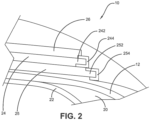
- a belt structure is located radially outward of the carcass ply 12.
- the belt structure has at least two inclined, crossed cord belt plies 24, 25 and a radially outer overlay ply 26.
- the cords are preferably inclined with respect to the circumferential direction of the example tire 10 in the first belt ply 24 and the cords in the second belt ply 25 directly adjacent the first belt ply 24 are preferably inclined at similar, but opposing, angles to the cords in the first belt ply 24. These angles are preferably both in a range of from 15 to 30 degrees.
- the overlay ply 26 Radially outward of the crossed cord belt plies 24, 25 is the overlay ply 26.
- the overlay ply 26 may have a lateral width equal to the maximum lateral width of the crossed cord plies 24, 25.
- the overlay ply has a lateral width in a range of from 85 to 97 percent.
- the radially inner second belt ply 25 is the laterally widest ply.
- the lateral width of the adjacent first belt ply 24 is preferably in a range of from 85 to 97 percent of the lateral width of the second belt ply.
- the lateral width of the adjacent overlay ply is preferably in a range of from 85 to 97 percent of the lateral width of the first belt ply 24.
- the overlay ply 26 is preferably reinforced with cords inclined at angles between of 15° and -15°, more preferably at angles between 5° and -5° or at angles between -2° to 2°, with respect to the circumferential direction of the example tire 10.
- the overlay ply 26 has a width less than a maximum width of the crossed cord plies of the belt structure 24, 25 ( FIGS. 1-2 ).
- first wrap around gum strips 244 are encompassed by first wrap around gum strips 244 (one shown).
- each first gum strip 244 extends on the radially upper side of the first belt ply 24 over a lateral distance of preferably 2 to 10 percent, more preferably 3 to 7 percent, of the lateral width of the first belt ply 24.
- each first gum strip 244 extends on the radially outer side of the first belt ply 24 over a lateral distance that is lower, preferably 5 to 15 percent lower, than the respective distance on the radially inner side of the first belt ply 24.
- each first gum strip 244 extends on the radially outer side partially under the overlay ply 26.
- the overlay ply 26 is in contact with each first gum strip 244 over a lateral distance in a range of from 1 to 5 percent or from 2 to 4 percent of the lateral width of the overlay belt ply 26.
- each second gum strip 254 extends on the radially upper side of the second belt ply 25 over a lateral distance of preferably 2 to 10 percent, more preferably 3 to 7 percent, of the lateral width of the second belt ply 25.
- each second gum strip 254 extends on the radially outer side of the second belt ply 25 over a lateral distance that is higher, preferably 15 to 40 percent higher, than the respective distance on the radially inner side of the second belt ply 25.
- the radially inner side of the first gum strip 244 and the radially outer side of the second gum strip 254 are adjacent to each other and partially overlap.
- each second gum strip 254 extends on the radially upper side of the second belt ply 25 laterally under the first gum strip 244 over a lateral distance in a range of from 0.5 to 3 percent of the lateral width of the first belt ply 24.
- the first and second wrap around gum strips 244, 254 may or may not include reinforcement structures such as cords, fibers, short fibers, fabric, etc.
- the construction of the tire 10 is symmetrical with respect to the equatorial plane of the tire 10.
- the disclosed belt/overlay construction 24, 25, 26, 244, 254 allows it to mitigate material flow in the area or the belt edges 242, 252 and to thereby prevent cords of the second belt ply 25 from directly contacting cords of the first belt ply 24 and cords of the first belt ply 24 from directly contacting cords of the overlay ply 26 there, thereby increasing durability of the crown area of the tire 10. This is of particular relevance when the tire 10 is a truck tire or when it is a self-supporting tire (run-flat tire).
- the axially outer edges of the overlay ply 26 preferably axially overlap a radially outer portion of each first wrap around gum strip 244.
- a radially inner portion of the first wrap around gum strips 244 preferably axially overlap a radially outer portion of each second wrap around gum strip 254.
Landscapes
- Engineering & Computer Science (AREA)
- Mechanical Engineering (AREA)
- Tires In General (AREA)
Applications Claiming Priority (1)
| Application Number | Priority Date | Filing Date | Title |
|---|---|---|---|
| US17/490,335 US20230098208A1 (en) | 2021-09-30 | 2021-09-30 | Wraparound structure for a belt package of a tire |
Publications (1)
| Publication Number | Publication Date |
|---|---|
| EP4159487A1 true EP4159487A1 (de) | 2023-04-05 |
Family
ID=83505984
Family Applications (1)
| Application Number | Title | Priority Date | Filing Date |
|---|---|---|---|
| EP22198164.0A Pending EP4159487A1 (de) | 2021-09-30 | 2022-09-27 | Umhüllungsstruktur für eine gürtelpackung eines reifens |
Country Status (2)
| Country | Link |
|---|---|
| US (1) | US20230098208A1 (de) |
| EP (1) | EP4159487A1 (de) |
Citations (4)
| Publication number | Priority date | Publication date | Assignee | Title |
|---|---|---|---|---|
| US20100084069A1 (en) * | 2008-10-03 | 2010-04-08 | Kiyoto Maruoka | Heavy duty tire |
| US20130153110A1 (en) * | 2010-10-21 | 2013-06-20 | Sumitomo Rubber Industries, Ltd. | Rubber composition for band topping, rubber composition for breaker edge strip, and pneumatic tire |
| US20130248075A1 (en) * | 2010-12-29 | 2013-09-26 | Sumitomo Rubber Industries, Ltd. | Pneumatic tire for heavy load |
| EP3181376A1 (de) * | 2015-12-14 | 2017-06-21 | Sumitomo Rubber Industries, Ltd. | Schwerlastluftreifen |
Family Cites Families (2)
| Publication number | Priority date | Publication date | Assignee | Title |
|---|---|---|---|---|
| BR8305477A (pt) * | 1982-10-18 | 1984-07-10 | Goodyear Tire & Rubber | Estrutura de cinta anular para pneu radial |
| JP2009173131A (ja) * | 2008-01-23 | 2009-08-06 | Toyo Tire & Rubber Co Ltd | 空気入りタイヤ |
-
2021
- 2021-09-30 US US17/490,335 patent/US20230098208A1/en active Pending
-
2022
- 2022-09-27 EP EP22198164.0A patent/EP4159487A1/de active Pending
Patent Citations (4)
| Publication number | Priority date | Publication date | Assignee | Title |
|---|---|---|---|---|
| US20100084069A1 (en) * | 2008-10-03 | 2010-04-08 | Kiyoto Maruoka | Heavy duty tire |
| US20130153110A1 (en) * | 2010-10-21 | 2013-06-20 | Sumitomo Rubber Industries, Ltd. | Rubber composition for band topping, rubber composition for breaker edge strip, and pneumatic tire |
| US20130248075A1 (en) * | 2010-12-29 | 2013-09-26 | Sumitomo Rubber Industries, Ltd. | Pneumatic tire for heavy load |
| EP3181376A1 (de) * | 2015-12-14 | 2017-06-21 | Sumitomo Rubber Industries, Ltd. | Schwerlastluftreifen |
Also Published As
| Publication number | Publication date |
|---|---|
| US20230098208A1 (en) | 2023-03-30 |
Similar Documents
| Publication | Publication Date | Title |
|---|---|---|
| US7409974B2 (en) | Self-supporting pneumatic tire with a partial inner liner | |
| US10226966B2 (en) | Pneumatic radial tire for passenger vehicle, method for using the tire, and tire-rim assembly including the tire | |
| US7900672B2 (en) | Pneumatic tire with annular reinforcing strip layer | |
| JPH07164833A (ja) | 公道外用空気入りタイヤ | |
| JP7298622B2 (ja) | 空気入りタイヤ | |
| JP3066332B2 (ja) | 空気入りラジアルタイヤ | |
| US11260704B2 (en) | Pneumatic tire | |
| EP1129870B1 (de) | Luftreifen | |
| US11254167B2 (en) | Pneumatic tyre | |
| JP4523704B2 (ja) | 空気入りタイヤ | |
| EP1116605B1 (de) | Luftreifen mit verbesserter Haltbarkeit der Wülste | |
| GB2283215A (en) | Motor-cycle radial tyre | |
| EP4159487A1 (de) | Umhüllungsstruktur für eine gürtelpackung eines reifens | |
| EP2045105A2 (de) | Reifen | |
| EP0748705A2 (de) | Luftreifen | |
| US20080011400A1 (en) | Pneumatic tire | |
| EP1422079A2 (de) | Reifen mit neuem Wulstkern | |
| EP3838630A1 (de) | Luftreifen | |
| EP4005826B1 (de) | Radialreifen | |
| EP4098461B1 (de) | Luftreifen | |
| US20220339975A1 (en) | Tire | |
| JP4486408B2 (ja) | 空気入りタイヤ | |
| WO2022091117A1 (en) | Heavy duty tire | |
| JP2017001432A (ja) | 空気入りタイヤ | |
| WO1998056605A1 (en) | Aircraft tire with embedded breaker plies |
Legal Events
| Date | Code | Title | Description |
|---|---|---|---|
| PUAI | Public reference made under article 153(3) epc to a published international application that has entered the european phase |
Free format text: ORIGINAL CODE: 0009012 |
|
| STAA | Information on the status of an ep patent application or granted ep patent |
Free format text: STATUS: THE APPLICATION HAS BEEN PUBLISHED |
|
| AK | Designated contracting states |
Kind code of ref document: A1 Designated state(s): AL AT BE BG CH CY CZ DE DK EE ES FI FR GB GR HR HU IE IS IT LI LT LU LV MC MK MT NL NO PL PT RO RS SE SI SK SM TR |
|
| STAA | Information on the status of an ep patent application or granted ep patent |
Free format text: STATUS: REQUEST FOR EXAMINATION WAS MADE |
|
| 17P | Request for examination filed |
Effective date: 20231005 |
|
| RBV | Designated contracting states (corrected) |
Designated state(s): AL AT BE BG CH CY CZ DE DK EE ES FI FR GB GR HR HU IE IS IT LI LT LU LV MC MK MT NL NO PL PT RO RS SE SI SK SM TR |
|
| RIC1 | Information provided on ipc code assigned before grant |
Ipc: B60C 9/20 20060101ALI20240418BHEP Ipc: B60C 9/18 20060101ALI20240418BHEP Ipc: B60C 9/22 20060101ALI20240418BHEP Ipc: B60C 9/28 20060101ALI20240418BHEP Ipc: B60C 17/00 20060101AFI20240418BHEP |