EP4159059B1 - Aerosolerzeugungsvorrichtung, induktor und herstellungsverfahren - Google Patents
Aerosolerzeugungsvorrichtung, induktor und herstellungsverfahren Download PDFInfo
- Publication number
- EP4159059B1 EP4159059B1 EP21812617.5A EP21812617A EP4159059B1 EP 4159059 B1 EP4159059 B1 EP 4159059B1 EP 21812617 A EP21812617 A EP 21812617A EP 4159059 B1 EP4159059 B1 EP 4159059B1
- Authority
- EP
- European Patent Office
- Prior art keywords
- sheet
- susceptor
- cavity
- generation device
- aerosol generation
- Prior art date
- Legal status (The legal status is an assumption and is not a legal conclusion. Google has not performed a legal analysis and makes no representation as to the accuracy of the status listed.)
- Active
Links
Images


Classifications
-
- A—HUMAN NECESSITIES
- A24—TOBACCO; CIGARS; CIGARETTES; SIMULATED SMOKING DEVICES; SMOKERS' REQUISITES
- A24F—SMOKERS' REQUISITES; MATCH BOXES; SIMULATED SMOKING DEVICES
- A24F40/00—Electrically operated smoking devices; Component parts thereof; Manufacture thereof; Maintenance or testing thereof; Charging means specially adapted therefor
- A24F40/40—Constructional details, e.g. connection of cartridges and battery parts
- A24F40/46—Shape or structure of electric heating means
- A24F40/465—Shape or structure of electric heating means specially adapted for induction heating
-
- A—HUMAN NECESSITIES
- A24—TOBACCO; CIGARS; CIGARETTES; SIMULATED SMOKING DEVICES; SMOKERS' REQUISITES
- A24F—SMOKERS' REQUISITES; MATCH BOXES; SIMULATED SMOKING DEVICES
- A24F40/00—Electrically operated smoking devices; Component parts thereof; Manufacture thereof; Maintenance or testing thereof; Charging means specially adapted therefor
- A24F40/70—Manufacture
-
- A—HUMAN NECESSITIES
- A24—TOBACCO; CIGARS; CIGARETTES; SIMULATED SMOKING DEVICES; SMOKERS' REQUISITES
- A24F—SMOKERS' REQUISITES; MATCH BOXES; SIMULATED SMOKING DEVICES
- A24F40/00—Electrically operated smoking devices; Component parts thereof; Manufacture thereof; Maintenance or testing thereof; Charging means specially adapted therefor
- A24F40/40—Constructional details, e.g. connection of cartridges and battery parts
- A24F40/42—Cartridges or containers for inhalable precursors
-
- A—HUMAN NECESSITIES
- A24—TOBACCO; CIGARS; CIGARETTES; SIMULATED SMOKING DEVICES; SMOKERS' REQUISITES
- A24F—SMOKERS' REQUISITES; MATCH BOXES; SIMULATED SMOKING DEVICES
- A24F40/00—Electrically operated smoking devices; Component parts thereof; Manufacture thereof; Maintenance or testing thereof; Charging means specially adapted therefor
- A24F40/50—Control or monitoring
- A24F40/51—Arrangement of sensors
-
- A—HUMAN NECESSITIES
- A24—TOBACCO; CIGARS; CIGARETTES; SIMULATED SMOKING DEVICES; SMOKERS' REQUISITES
- A24F—SMOKERS' REQUISITES; MATCH BOXES; SIMULATED SMOKING DEVICES
- A24F40/00—Electrically operated smoking devices; Component parts thereof; Manufacture thereof; Maintenance or testing thereof; Charging means specially adapted therefor
- A24F40/50—Control or monitoring
- A24F40/53—Monitoring, e.g. fault detection
-
- A—HUMAN NECESSITIES
- A24—TOBACCO; CIGARS; CIGARETTES; SIMULATED SMOKING DEVICES; SMOKERS' REQUISITES
- A24F—SMOKERS' REQUISITES; MATCH BOXES; SIMULATED SMOKING DEVICES
- A24F40/00—Electrically operated smoking devices; Component parts thereof; Manufacture thereof; Maintenance or testing thereof; Charging means specially adapted therefor
- A24F40/50—Control or monitoring
- A24F40/57—Temperature control
-
- H—ELECTRICITY
- H05—ELECTRIC TECHNIQUES NOT OTHERWISE PROVIDED FOR
- H05B—ELECTRIC HEATING; ELECTRIC LIGHT SOURCES NOT OTHERWISE PROVIDED FOR; CIRCUIT ARRANGEMENTS FOR ELECTRIC LIGHT SOURCES, IN GENERAL
- H05B6/00—Heating by electric, magnetic or electromagnetic fields
- H05B6/02—Induction heating
- H05B6/10—Induction heating apparatus, other than furnaces, for specific applications
- H05B6/105—Induction heating apparatus, other than furnaces, for specific applications using a susceptor
-
- A—HUMAN NECESSITIES
- A24—TOBACCO; CIGARS; CIGARETTES; SIMULATED SMOKING DEVICES; SMOKERS' REQUISITES
- A24F—SMOKERS' REQUISITES; MATCH BOXES; SIMULATED SMOKING DEVICES
- A24F40/00—Electrically operated smoking devices; Component parts thereof; Manufacture thereof; Maintenance or testing thereof; Charging means specially adapted therefor
- A24F40/20—Devices using solid inhalable precursors
Definitions
- This invention relates to the field of heat not burning e-cigarette technologies, and in particular, to an aerosol generation device, a susceptor, and a manufacturing method.
- Tobacco products for example, cigarettes and cigars
- cigarettes and cigars burn tobacco during use to produce tobacco smoke.
- Attempts are made to replace these products that burn tobacco by manufacturing products that release compounds without burning.
- a heating device that releases a compound by heating rather than burning a material.
- the material may be tobacco or other non-tobacco products, where the non-tobacco products may or may not contain nicotine.
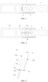
- the prior art proposes a heating device of electromagnetic induction heating type, where the structure of the device may refer to FIG. 1 .
- a susceptor 2 is penetrated by an alternating magnetic field generated by an induction coil 3 to implement induction heating, thereby heating the tobacco product 1.
- the heating device uses a temperature sensor 4 that is closely attached to the susceptor 2 to sense a real-time operating temperature of the susceptor 2, and adjusts a parameter of the alternating magnetic field generated by the induction coil 3 according to a sensed result of the temperature sensor 4 to make the susceptor 2 be within an appropriate heating temperature range.
- the temperature sensor 4 is usually made of a thermistor metal material, which generates heat under an alternating magnetic field; and on the other hand, the temperature sensor 4 and the susceptor 2 made of a metal material each generate an induced current, which affects a sensing signal outputted by the temperature sensor 4 and affects an accuracy of the sensing signal.
- EP 4 133 956 A1 discloses an aerosol generation apparatus, for heating a smokable material to generate an aerosol, comprising a susceptor, wherein the susceptor comprises an avoidance portion and a heating portion sequentially provided along the direction close to the proximal end; and the size of at least a part of the avoidance portion along the cross-sectional direction of the cavity is less than the size of the heating portion along the cross-sectional direction of the cavity, such that a certain gap is kept between the avoidance portion and the smokable material when the susceptor is inserted into the smokable material.
- WO 2015/177044 A1 discloses a cartridge for use in an electrically heated aerosol-generating system.
- WO 2018/220558 A1 discloses an electronic device for receiving a consumable comprising an aerosol generating substrate.
- this invention provides an aerosol generation device, a susceptor, and a manufacturing method.
- An aerosol generation device provided in this invention is configured to heat an inhalable material to generate an aerosol, and the device includes:
- the susceptor is formed into a sheet shape extending in an axial direction of the cavity, and includes a first sheet-like body and a second sheet-like body opposite to each other in a thickness direction, where the first sheet-like body is connected to the second sheet-like body.
- the first sheet-like body includes: a first part extending straight in the axial direction of the cavity, and a second part formed by at least a part of the first part protruding outward in the thickness direction; and the accommodation cavity is formed between the second part of the first sheet-like body and the second sheet-like body.
- the first sheet-like body further includes a third part formed by the first part extending outward in a width direction, to support or hold the susceptor by the third part.
- the cavity includes an opening end that removably receives the inhalable material; and a protrusion height of at least a part of the second part relative to the first part gradually decreases in a direction of getting closer to the opening end.
- At least a part of a third part of the first sheet-like body protrudes relatively to other parts in the thickness direction.
- the second part is formed in a manner that a cross section is substantially a triangle or circular arc.
- the second sheet-like body includes: a fourth part extending straight in the axial direction of the cavity, and a fifth part formed by at least a part of the fourth part protruding outward in the thickness direction; and the fifth part is arranged opposite to the second part, and the accommodation cavity is formed between the fifth part and the second part.
- the temperature sensor further includes a conductive connection portion at least partially penetrating from inside of the accommodation cavity to outside of the susceptor, so that a temperature sensed by the temperature sensor is capable of being received through the conductive connection portion during use.
- the second part of the first sheet-like body is formed by punching a flat sheet-like metal or metal plate material.
- the cavity includes an opening end that removably receives the inhalable material; and at least a part of the accommodation cavity is formed into a tapered region with a gradually decreasing cross-sectional area as getting closer to the opening end; and the temperature sensor is accommodated or encapsulated in the tapered region.
- the susceptor is formed into a sheet shape extending in the axial direction of the cavity, and includes a first surface and a second surface facing away from each other in a thickness direction, and the first surface and the second surface are flat surfaces, where the accommodation cavity is located between the first surface and the second surface.
- the susceptor includes a first sheet-like part and a second sheet-like part opposite to each other in the thickness direction, and the accommodation cavity is formed by defining between the first sheet-like part and the second sheet-like part.
- first sheet-like part and the second sheet-like part are formed by folding a sheet-like body around an axis.
- first sheet-like part and the second sheet-like part are symmetrical with respect to the axis.
- the sheet-like body is prepared by chemical etching.
- the sheet-like body includes a dent arranged along the axis.
- first sheet-like part forms the first surface along an outer surface in the thickness direction
- second sheet-like part forms the second surface along an outer surface in the thickness direction
- accommodation cavity is formed between an inner surface of the first sheet-like part in the thickness direction and an inner surface of the second sheet-like part in the thickness direction.
- the accommodation cavity includes a first groove extending along the inner surface of the first sheet-like part in the thickness direction; and/or, the accommodation cavity includes a second groove extending along the inner surface of the second sheet-like part in the thickness direction.
- first sheet-like part and/or the second sheet-like part further includes a base part extending outward in a width direction, so as to support or hold the susceptor by the base part.
- the temperature sensor includes a first couple wire and a second couple wire made of different materials.
- This invention further provides a susceptor for an aerosol generation device, the susceptor being configured to be penetrated by a changing magnetic field to generate heat to heat an inhalable material, where the susceptor is formed into a sheet shape, the susceptor includes an accommodation cavity extending in a length direction, and the accommodation cavity is configured to accommodate or encapsulate a temperature sensor configured to sense a temperature of the susceptor.
- the susceptor includes a first surface and a second surface facing away from each other in a thickness direction, and the first surface and the second surface are flat surfaces, where the accommodation cavity is located between the first surface and the second surface.
- the susceptor includes a first sheet-like body and a second sheet-like body opposite to each other in the thickness direction; and the first sheet-like body is connected to the second sheet-like body to form the accommodation cavity.
- This invention further provides a manufacturing method for a susceptor for an aerosol generation device, where the susceptor is configured to be penetrated by a changing magnetic field to generate heat to heat an inhalable material, and the method includes the following steps: providing a first sheet-like body and a second sheet-like body opposite to each other in a thickness direction, and forming an accommodation cavity extending in a length direction between the first sheet-like body and the second sheet-like body; and accommodating or encapsulating, inside the accommodation cavity, a temperature sensor configured to sense a temperature of the susceptor.
- the above aerosol generation device, susceptor, and manufacturing method in this invention by encapsulating or accommodating the temperature sensor inside the susceptor, on one hand, an impact of a magnetic field on a sensing portion can be substantially isolated; and on the other hand, the susceptor and the temperature sensor can be integrated to improve stability of installation and accuracy of temperature measurement. Moreover, it is convenient for overall replacement and installation.
- An aerosol generation device provided in this embodiment of this invention has a structure shown in FIG. 2 , and includes:
- the inductance coil L may include a cylindrical inductor coil wound into a spiral shape as shown in FIG. 2 .
- the cylindrical inductance coil L wound into a spiral shape may have a radius r ranging from about 5 mm to about 10 mm, and in particular, the radius r may be about 7 mm.
- a length of the cylindrical inductance coil L wound into a spiral shape may range from about 8 mm to about 14 mm, and a number of turns of the inductance coil L may range from about 8 to 15.
- an inner volume may range from about 0.15 cm 3 to about 1.10 cm 3 .
- a frequency of the alternating current supplied to the inductance coil L by the circuit 20 ranges from 80 KHz to 400 KHz. More specifically, the frequency may range from about 200 KHz to 300 KHz.
- a direct current voltage provided by the battery cell 10 ranges from about 2.5 V to about 9.0 V, and an amperage of the direct current by which the battery cell 10 can provide ranges from about 2.5 A to about 20 A.
- the susceptor 30 in FIG. 2 is manufactured by a metal or alloy material with appropriate magnetic permeability, so that induction heating corresponding to a magnetic field can be formed during use, thereby heating the received inhalable material A to generate an aerosol for inhalation.
- These susceptors 30 may be made of grade 420 stainless steel (SS420) and alloy materials including iron and nickel (such as J85/J66 Permalloy).
- the aerosol generation device further includes a tubular holder 40 for arranging the inductance coil L and installing the susceptor 30.
- Materials of the tubular holder 40 may include a high temperature resistant non-metal material such as PEEK or ceramic.
- the inductance coil L is arranged on an outer wall of the tubular holder 40 in a spiral winding manner, and at least a part of the tubular holder 40 is hollow to form the cavity configured to receive the inhalable material A.
- a sheet-like construction of the susceptor 30 has a first end 31 and a second end 32.
- the first end 31 is opposite to an opening the cavity configured to receive the inhalable material A.
- the first end 31, as a free end, is formed into a tip shape to facilitate insertion into the inhalable material A received in the cavity through an opening end, and the second end 32, as an end portion for installation and connection, is configured to provide support through the tubular holder 40 to enable the susceptor 30 to be stably held, installed, and fixed in the device.
- a construction of the susceptor 30 is formed by a first sheet-like body 310 and a second sheet-like body 320 opposite to each other in a thickness direction together.
- the first sheet-like body 310 includes a flat first part 311, a second part 312 formed by the first part 311 protruding outward in the thickness direction, and a third part 313 formed by at least a part of the first part 311 close to the second end 32 extending in a width direction.
- the shape corresponding to the second sheet-like body 320 is similar to that of the first sheet-like body 310, likewise including a flat fourth part 321, a fifth part 322 formed by the fourth part 321 protruding outward in the thickness direction, and a sixth part 323 formed by at least a part of the fourth part 321 close to the second end 32 extending in the width direction.
- an accommodation cavity 330 configured to accommodate and encapsulate a temperature sensor 340 is formed between them.
- the accommodation cavity 330 is formed by a first sunken structure 331 formed by the second part 312 of the first sheet-like body 310 and a second sunken structure 332 formed by the fifth part 322 of the second sheet-like body 320 together.
- a sensing part 341 of the temperature sensor 340 is accommodated and encapsulated inside the accommodation cavity 330 and may be encapsulated and fixed through gluing or the like.
- an electrical connection part 342 of the temperature sensor 340 passes through the second end 32 from the inside of the accommodation cavity 330 to the outside of the susceptor 30 in a form of being designed into an elongated pin, thereby facilitating the connection to the circuit 20, and then the circuit 20 may receive a sensing signal of the sensing part 341 through the electrical connection part 342.
- the temperature sensor 40 is encapsulated inside the accommodation cavity 330 that is substantially shielded by a magnetic field, and the sensing part 341 closely abuts against the first sheet-like body 310 and/or the second sheet-like body 320, so as to stably or accurately detect the temperature of the susceptor 30 and avoid interference of the magnetic field.
- the temperature sensor 340 may be a thermistor type temperature sensor, such as PT1000, that calculates a temperature by monitoring changes in a resistor, or may be a thermocouple type temperature sensor that calculates a temperature by calculating thermoelectromotive force of two ends.
- the second part 312 of the first sheet-like body 310 and/or the fifth part 322 of the second sheet-like body 320 is formed or prepared by stamping the above flat sheet-like susceptive material such as a metal plate member.
- the first sheet-like body 310 and the second sheet-like body 320 may be fixed as a whole by welding such as laser welding.
- the accommodation cavity 330 extends in an axial direction of the susceptor 30.
- a cross section of the accommodation cavity 330 may substantially be rhombic, circular, rectangular, or in other shapes.
- the second part 312 has a tapered portion 3121 with a gradually decreasing cross-sectional area as getting closer to the first end 31 of the susceptor 30, for example, the tapered portion 3121 has a cone shape, triangular cone shape, or the like. And, the second part 312 is configured to reduce resistance during being inserted into the inhalable material A.
- the tapered portion 3121 of the second part 312, or the combination with the corresponding fifth part 322 with a similar configuration may cause a formed front end part of the accommodation cavity 330 close to the first end 31 to be a tapered shape.
- the sensing part 341 of the temperature sensor 340 abuts against the tapered front end part of the accommodation cavity 330, so as to facilitate fastening and installation.
- the thickness-direction size of a part in the susceptor 30 forming the accommodation cavity 330 and composed of the second part 312 and the fifth part 322 is greater than other parts in the susceptor 30.
- a thickness size of the accommodation cavity 330 formed by the second part 312 and the fifth part 322 gradually increases inward in the width direction, so that an outer surface of the susceptor 30 formed by the second part 312 and the fifth part 322 changes gradually.
- a contact area with the inhalable material A is increased to improve efficiency of heat transfer; and on the other hand, the resistance of inserting the susceptor 30 into the inhalable material A may be reduced.
- a second sheet-like body 320a/320b of the susceptor 30a/30b is a flat shape. And, only a second part 312a/312b formed by stamping or the like on the first sheet-like body 310a/310b and protruding outward in the thickness direction exists, and an accommodation cavity 330a/330b for accommodating or encapsulating the temperature sensor is formed between the second part 312a/312b and second sheet-like body 320a/320b.
- a shape of a cross section of the second part 312a/312b may substantially be a triangle or circular arc shape with a thickness size gradually increasing inward in the width direction.
- a protrusion size of the second part 312a/312b in the thickness direction is greater than the thickness size of the first part 311a/311b.
- a thickness of a third part 313c of a first sheet-like body 310c of a susceptor 30c along the susceptor 30c has a greater size than a first part 311c and a second part 312c, so that the third part 313c protrudes relative to other parts on the thickness direction, so as to facilitate installation and holding inside the device.
- This invention further proposes a method for manufacturing the susceptor in Embodiment 1.
- method steps including the following steps:
- This invention further provides an aerosol generation device.
- an aerosol generation device Unlike the aerosol generation device provided in Embodiment 1, referring to FIG. 9 , in order to facilitate support and fixation for a second end 320, at least a part of a susceptor 30 close to the second end 320 has a base part 33 with an enlarged size. For example, the base part 33 is enlarged in a width direction.
- an accommodating space or a holding space is provided inside the susceptor 30, and is configured to accommodate, encapsulate, or hold a temperature sensor 34 extending in a length direction.
- the temperature sensor 34 is configured to sense a temperature of the susceptor 30 during operation.
- at least a part of the temperature sensor 34 extends from the second end 320, so as to facilitate connection to a circuit 20.
- a part of the temperature sensor 34 extending or exposed outside the susceptor 30 is in a form of an elongated pin.
- the temperature sensor 34 may be a thermistor type temperature sensor, such as PT1000, that calculates a temperature by monitoring changes in a resistor or a thermocouple type temperature sensor that calculates a temperature by calculating thermoelectromotive force of two ends.
- PT1000 thermistor type temperature sensor
- the sheet-like susceptor 30 is formed by stacking a first sheet-like part 31 and a second sheet-like part 32 in the thickness direction.
- an outer surface of the sheet-like susceptor 30 is flat.
- This invention further proposes a method suitable for mass manufacturing of the above susceptor 30, the method specifically including the following steps: S10: Acquire a sheet-like sensing substrate 100 for manufacturing a susceptor 30a, and process the sheet-like sensing substrate 100 to form several susceptor precursors 30a, as shown in FIG. 10 .
- the material of the sheet-like sensing substrate 100 is the above-described metal material having susceptibility, such as a 0.5 mm thick NiFe alloy soft magnetic board.
- a manner of processing to form the susceptor precursor 30a may include a manner of chemical etching, and the susceptor precursor 30a is formed after the superfluous part is etched and removed.
- the several susceptor precursors 30a obtained by processing are arranged in a matrix.
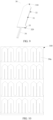
- a specific structure of the susceptor precursor 30a further refers to FIG. 11 , including a first sheet-like part 31 and a second sheet-like part 32 on the same plane.
- the first sheet-like part 31 and the second sheet-like part 32 are connected rather than separated.
- the first sheet-like part 31 and the second sheet-like part 32 are symmetrical, and specifically, are bilaterally symmetrical along a central axis L in FIG. 12 .
- a first accommodation groove 311 for accommodating and holding the temperature sensor 34 is arranged on the first sheet-like part 31, or a second accommodation groove 321 for accommodating and holding the temperature sensor 34 may be further arranged on the second sheet-like part 32.
- the temperature sensor 34 is placed into the first accommodation groove 311 of the first sheet-like part 31, the second sheet-like part 32 is turned over or folded towards the first sheet-like part 31 along a direction of an arrow R around the central axis L, the temperature sensor 34 is clamped or fixed between the first sheet-like part 31 and the second sheet-like part 32 after the second sheet-like part 32 is turned over, and then the first sheet-like part 31 is combined stably with the second sheet-like part 32 through laser welding or the like. In this way, the susceptor 30 shown in FIG. 3 is obtained.
- FIG. 11 and FIG. 12 for ease of turning over the second sheet-like part 32 towards the first sheet-like part 31, several dents or grooves 35 arranged around the central axis L are arranged on the susceptor precursor 30a.
- the susceptor precursor 30a with the dents or grooves 35 is conducive to the operation process of turning over or folding.
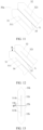
- FIG. 13 is a schematic structural diagram of a susceptor precursor 30b according to another variation implementation.
- the susceptor precursor 30b includes a first sheet-like part 31b and a second sheet-like part 32b opposite to each other in a length direction.
- the susceptor precursor 30b further includes a dent 35b located between the first sheet-like part 31b and the second sheet-like part 32b in the length direction, where the dent 35b extends in the width direction.
- the susceptor is obtained by turning over or folding the first sheet-like part 31b towards the second sheet-like part 32b with the dent 35b as an axis.
- a first accommodation groove 311b accommodating the temperature sensor 34 is further arranged on the first sheet-like part 31b; and/or, a second accommodation groove 321b is further arranged on the second sheet-like part 32b.
- a first sheet-like part 31c and a second sheet-like part 32c of a susceptor precursor 30c is obtained by fixing after turning over with a dashed line m as an axis.
- the susceptor 30 is about 19 mm in length, 4.9 mm in width, and about 0.5 mm in width.
- an extending length of the first accommodation groove 311/311b/311c and/or the second accommodation groove 321/321 b/321c extending from the second end 320 to the first end 310 is about one-half to two-thirds of a length of the susceptor 30.
- a region of this length is a region where heat is most concentrated in the susceptor 30 during operation. When a front end of the temperature sensor 34 abuts against this region, the temperature of the susceptor 30 can be obtained more accurately.
- the first accommodation groove 311/311b/311c and/or the second accommodation groove 321/321b/321c is about 0.1 mm in depth.
- This invention further proposes a method for manufacturing the susceptor in Embodiment 3, the method including the following steps: S100: Acquire a sheet-like substrate 100a made of a susceptive material, and cover an etching mask 200a on a surface of the sheet-like substrate 100, as shown in FIG. 15 .
- a feeding material of the sheet-like substrate 100a is a coil, and a board cut into the above size from the coil has a certain bending degree. It is necessary to shape the coil by an appropriate pressure (usually less than 10 MPa) before use, so that a curved metal coil is subjected to a certain plastic deformation, and is shaped into a flat sheet-like substrate 100a from a curved metal coil.
- a light-painted film is used as the etching mask 200a in photochemical etching generally.
- the etching mask 200a includes a pattern 210a having the same shape with the susceptor, and a non-pattern blank region 220a.
- S200 Etch the sheet-like substrate 100a covered with the etching mask 200a.
- An acid etching liquid for example, an etching liquid including hydrofluoric acid, is generally used to etch.
- etching a part of the sheet-like substrate 100a covered with the pattern 210a is not corroded, while a part corresponding to the blank region 220a is corroded and removed.
- several susceptors identical to the pattern 210a are formed on the sheet-like substrate 100a; and the susceptors may be lightly broken off manually to be detached, thereby obtaining a large number of manufactured susceptors.
- one sheet-like substrate 100a may be etched to obtain 100 to 200 susceptors simultaneously.
- the etching processing does not generate processing stress on one hand, and does not cause a crystalline phase structure of the internal substrate to change on the other hand, so that the manufactured susceptor can maintain magnetic properties comparable to those of soft magnetic materials, thereby having high heating efficiency in use.
- an edge of the obtained susceptor has smooth rounded comers, and a smooth surface of the edge has low surface free energy, which is conducive to reducing adhesion of slag or condensate of an aerosol generation product, while the aesthetic of a surface is maintained.
- the etching process in the above step is performed by conventional photochemical wet etching.
- Detailed steps include:
- This invention further proposes a susceptor 30d manufactured by the manufacturing method in Embodiment 4. As shown in FIG. 16 , the susceptor 30d is provided with a notch 36d. Subsequently, a first couple wire and a second couple wire made of different materials are welded onto an inner wall of the notch 36d by laser welding, thereby forming a thermocouple 34d configured to sense a temperature of the susceptor 30d.
- a nickel chromium alloy wire is used as the first couple wire of the thermocouple 34d as a positive electrode, and a K-type thermocouple made of a nickel silicon alloy wire is used as the second couple wire as a negative electrode.
- an impact of a magnetic field on a sensing portion can be substantially isolated; and on the other hand, the susceptor and the temperature sensor can be integrated to improve stability of installation and accuracy of temperature measurement. Moreover, it is convenient for overall replacement and installation.
Landscapes
- Physics & Mathematics (AREA)
- Electromagnetism (AREA)
- Measuring Temperature Or Quantity Of Heat (AREA)
- Container, Conveyance, Adherence, Positioning, Of Wafer (AREA)
Claims (13)
- Aerosolerzeugungsvorrichtung, die so konfiguriert ist, dass sie ein inhalierbares Material erhitzt, um ein Aerosol zu erzeugen, wobei die Vorrichtung Folgendes umfasst:einen Hohlraum, der zur Aufnahme des inhalierbaren Materials konfiguriert ist;einen Magnetfeldgenerator, der so konfiguriert ist, dass er ein wechselndes Magnetfeld erzeugt;einen Suszeptor (30), der so konfiguriert ist, dass er von dem sich ändernden Magnetfeld durchdrungen wird, um Wärme zu erzeugen, um das inhalierbare Material, das in dem Hohlraum aufgenommen ist, zu erhitzen, wobei ein Aufnahmehohlraum (330, 330a, 330b), der sich in einer Längsrichtung erstreckt, in dem Suszeptor (30) angeordnet ist; undeinen Temperatursensor (340), der so konfiguriert ist, dass er die Temperatur des Suszeptors (30) erfasst, und der im Inneren des Aufnahmehohlraums (330, 330a, 330b) untergebracht oder eingekapselt ist,wobei der Suszeptor zu einer Blattform geformt ist (30), die sich in einer axialen Richtung des Hohlraums erstreckt, und einen ersten blattartigen Körper (310) und einen zweiten blattartigen Körper (320) umfasst, die einander in einer Dickenrichtung gegenüberliegen, wobeider erste blattförmige Körper (310) ist mit dem zweiten blattförmigen Körper (320) verbunden.
- Aerosolerzeugungsvorrichtung nach Anspruch 1, wobei der erste blattartige Körper (310) umfasst: einen ersten Teil (311, 311a, 311b, 311c), der sich gerade in der axialen Richtung des Hohlraums erstreckt, und einen zweiten Teil (312, 312a, 312b, 312c), der durch mindestens einen Teil des ersten Teils (311, 311a, 311b, 311c) gebildet wird, der in der Dickenrichtung nach außen vorsteht; und
der Aufnahmehohlraum (330, 330a, 330b) zwischen dem zweiten Teil (312, 312a, 312b, 312c) des ersten plattenförmigen Körpers (310) und dem zweiten plattenförmigen Körper (320) gebildet wird. - Aerosolerzeugungsvorrichtung nach Anspruch 2, wobei der erste flächige Körper (310) ferner einen dritten Teil (313, 313a, 313b, 313c) umfasst, der durch den ersten Teil (311, 311a, 311b, 311c) gebildet wird, der sich in einer Breitenrichtung nach außen erstreckt, um den Suszeptor (30) durch den dritten Teil (313, 313a, 313b, 313c) zu stützen oder zu halten.
- Aerosolerzeugungsvorrichtung nach Anspruch 2, wobei der Hohlraum ein sich öffnendes Ende umfasst, das das inhalierbare Material aufnimmt; und
eine Vorsprungshöhe von mindestens einem Teil des zweiten Teils (312, 312a, 312b, 312c) relativ zum ersten Teil (311, 311a, 311b, 311c) allmählich in einer Richtung abnimmt, in der er sich dem Öffnungsende nähert. - Aerosolerzeugungsvorrichtung nach Anspruch 4, wobei zumindest ein Teil eines dritten Teils (313, 313a, 313b, 313c) des ersten flächigen Körpers (310) relativ zu anderen Teilen in Richtung der Dicke vorsteht.
- Aerosolerzeugungsvorrichtung nach Anspruch 2, wobei der zweite Teil (312, 312a, 312b, 312c) so geformt ist, dass sein Querschnitt im Wesentlichen ein Dreieck oder ein Kreisbogen ist.
- Aerosolerzeugungsvorrichtung nach einem der Ansprüche 2 bis 5, wobei der zweite blattförmige Körper (320) umfasst: einen vierten Teil (321), der sich gerade in der axialen Richtung des Hohlraums erstreckt, und einen fünften Teil (322), der durch mindestens einen Teil des vierten Teils (321) gebildet wird, der in der Dickenrichtung nach außen vorsteht; und
der fünfte Teil (322) gegenüber dem zweiten Teil (312, 312a, 312b, 312c) angeordnet ist, und der Aufnahmehohlraum (330, 330a, 330b) zwischen dem fünften Teil (322) und dem zweiten Teil (312, 312a, 312b, 312c) gebildet wird. - Aerosolerzeugungsvorrichtung nach einem der Ansprüche 2 bis 5, wobei der Temperatursensor (340) ferner einen leitenden Verbindungsabschnitt umfasst, der zumindest teilweise von der Innenseite des Aufnahmehohlraums (330, 330a, 330b) zur Außenseite des Suszeptors (30) durchdringt, so dass eine von dem Temperatursensor (340) erfasste Temperatur während der Verwendung durch den leitenden Verbindungsabschnitt aufgenommen werden kann.
- Aerosolerzeugungsvorrichtung nach einem der Ansprüche 2 bis 5, wobei der zweite Teil (312, 312a, 312b, 312c) des ersten blechartigen Körpers (310) durch Stanzen eines flachen blechartigen Metall- oder Metallplattenmaterials gebildet ist.
- Aerosolerzeugungsvorrichtung nach Anspruch 1, wobei der Temperatursensor (340) einen ersten Koppeldraht und einen zweiten Koppeldraht aus unterschiedlichen Materialien umfasst.
- Suszeptor (30) für eine Aerosolerzeugungsvorrichtung, wobei der Suszeptor (30) so konfiguriert ist, dass er von einem sich ändernden Magnetfeld durchdrungen wird, um Wärme zu erzeugen, um ein inhalierbares Material zu erwärmen, wobei der Suszeptor (30) zu einer Blattform geformt ist, der Suszeptor (30) einen Aufnahmehohlraum (330, 330a, 330b) umfasst, der sich in einer Längsrichtung erstreckt, und der Aufnahmehohlraum (330, 330a, 330b) so konfiguriert ist, dass er einen Temperatursensor (340) aufnimmt oder einkapselt, der so konfiguriert ist, dass er eine Temperatur des Suszeptors (30) erfasst,wobeider Suszeptor (30) einen ersten blattartigen Körper (310) und einen zweiten blattartigen Körper (320) umfasst, die einander in der Dickenrichtung gegenüberliegen; und der erste blattartige Körper (310) mit dem zweiten blattartigen Körper (320) verbunden ist, um den Aufnahmehohlraum (330, 330a, 330b) zu bilden.
- Suszeptor (30) nach Anspruch 11, wobei der Suszeptor (30) eine erste Oberfläche und eine zweite Oberfläche aufweist, die in einer Dickenrichtung voneinander abgewandt sind, und die erste Oberfläche und die zweite Oberfläche flache Oberflächen sind, wobei der Aufnahmehohlraum (330, 330a, 330b) zwischen der ersten Oberfläche und der zweiten Oberfläche angeordnet ist.
- Herstellungsverfahren für einen Suszeptor (30) für eine Aerosolerzeugungsvorrichtung, wobei der Suszeptor (30) so konfiguriert ist, dass er von einem sich ändernden Magnetfeld durchdrungen wird, um Wärme zu erzeugen, um ein inhalierbares Material zu erwärmen; und das Verfahren umfasst die folgenden Schritte:
Bereitstellen eines ersten flächigen Körpers (310) und eines zweiten flächigen Körpers (320), die einander in einer Dickenrichtung gegenüberliegen, und Bilden eines Aufnahmehohlraums (330, 330a, 330b), der sich in einer Längsrichtung zwischen dem ersten flächigen Körper (310) und dem zweiten flächigen Körper (320) erstreckt; und Aufnehmen oder Einkapseln eines Temperatursensors (340), der so konfiguriert ist, dass er eine Temperatur des Suszeptors (30) erfasst, im Inneren des Aufnahmehohlraums (330, 330a, 330b).
Applications Claiming Priority (3)
| Application Number | Priority Date | Filing Date | Title |
|---|---|---|---|
| CN202010451178.3A CN113712266A (zh) | 2020-05-25 | 2020-05-25 | 气雾生成装置、感受器及制备方法 |
| CN202010804879.0A CN114073333A (zh) | 2020-08-12 | 2020-08-12 | 气雾生成装置及感受器 |
| PCT/CN2021/095820 WO2021238922A1 (zh) | 2020-05-25 | 2021-05-25 | 气雾生成装置、感受器及制备方法 |
Publications (3)
| Publication Number | Publication Date |
|---|---|
| EP4159059A1 EP4159059A1 (de) | 2023-04-05 |
| EP4159059A4 EP4159059A4 (de) | 2023-11-22 |
| EP4159059B1 true EP4159059B1 (de) | 2025-04-02 |
Family
ID=78722988
Family Applications (1)
| Application Number | Title | Priority Date | Filing Date |
|---|---|---|---|
| EP21812617.5A Active EP4159059B1 (de) | 2020-05-25 | 2021-05-25 | Aerosolerzeugungsvorrichtung, induktor und herstellungsverfahren |
Country Status (5)
| Country | Link |
|---|---|
| US (1) | US20230354920A1 (de) |
| EP (1) | EP4159059B1 (de) |
| JP (1) | JP7542083B2 (de) |
| KR (1) | KR102878219B1 (de) |
| WO (1) | WO2021238922A1 (de) |
Families Citing this family (1)
| Publication number | Priority date | Publication date | Assignee | Title |
|---|---|---|---|---|
| CN116268621A (zh) * | 2021-12-21 | 2023-06-23 | 深圳市合元科技有限公司 | 气雾生成装置及用于气雾生成装置的加热器 |
Family Cites Families (23)
| Publication number | Priority date | Publication date | Assignee | Title |
|---|---|---|---|---|
| EP3632244B1 (de) * | 2014-05-21 | 2023-04-12 | Philip Morris Products S.A. | Aerosolbildende artikel mit internem suszeptor |
| TWI669072B (zh) * | 2014-05-21 | 2019-08-21 | 瑞士商菲利浦莫里斯製品股份有限公司 | 電熱式霧劑產生系統及用於此系統中之匣筒 |
| MX375268B (es) * | 2015-02-05 | 2025-03-06 | Philip Morris Products Sa | Dispositivo generador de aerosol con calentador anclado. |
| US20170055580A1 (en) * | 2015-08-31 | 2017-03-02 | British American Tobacco (Investments) Limited | Apparatus for heating smokable material |
| US20170119048A1 (en) * | 2015-10-30 | 2017-05-04 | British American Tobacco (Investments) Limited | Article for Use with Apparatus for Heating Smokable Material |
| TW201902372A (zh) | 2017-05-31 | 2019-01-16 | 瑞士商菲利浦莫里斯製品股份有限公司 | 氣溶膠產生裝置之加熱構件 |
| CN207544334U (zh) * | 2017-09-04 | 2018-06-29 | 深圳云蒙科技有限公司 | 一种用于加热不燃烧卷烟的电热加热元件 |
| CN109805449B (zh) * | 2017-11-22 | 2023-07-04 | 湖南中烟工业有限责任公司 | 一种磁感应雾化抽吸装置 |
| CN109805446B (zh) * | 2017-11-22 | 2023-06-16 | 湖南中烟工业有限责任公司 | 一种磁感应雾化装置及磁感应发热抽吸装置 |
| CN207766584U (zh) | 2018-01-31 | 2018-08-24 | 深圳市合元科技有限公司 | 一种加热装置及电子烟 |
| WO2019199010A1 (ko) | 2018-04-09 | 2019-10-17 | 주식회사 아모센스 | 궐련형 전자담배장치용 발열히터 |
| CN208540206U (zh) * | 2018-05-31 | 2019-02-22 | 广东国研新材料有限公司 | 一种加热烟草用电磁感应加热装置 |
| CN109077361A (zh) | 2018-09-21 | 2018-12-25 | 李东 | 一种发热组件及电子烟 |
| PL3855953T3 (pl) * | 2018-09-25 | 2023-05-02 | Philip Morris Products S.A. | Zespół grzejny i sposób indukcyjnego ogrzewania substratu do wytwarzania aerozolu |
| KR102342331B1 (ko) * | 2018-12-07 | 2021-12-22 | 주식회사 케이티앤지 | 궐련을 가열하는 히터 조립체 및 이를 포함하는 에어로졸 생성 장치 |
| CN110169594A (zh) * | 2018-12-25 | 2019-08-27 | 惠州市沛格斯科技有限公司 | 加热模组、可控加热模组以及电子烟具 |
| CN109619692B (zh) * | 2019-01-23 | 2023-11-21 | 中国科学技术大学 | 一种内插式旋转摩擦加热不燃烧烟草的方法及装置 |
| CN209931492U (zh) * | 2019-03-14 | 2020-01-14 | 深圳市合元科技有限公司 | 加热器及低温烘烤烟具 |
| CN111165912A (zh) * | 2020-01-09 | 2020-05-19 | 深圳市吉迩科技有限公司 | 一种涡流感应线圈的安装方法、加热装置及气溶胶产生装置 |
| CN113508930B (zh) | 2020-04-11 | 2025-09-09 | 深圳市合元科技有限公司 | 气雾生成装置及感受器 |
| CN212852505U (zh) * | 2020-05-25 | 2021-04-02 | 深圳市合元科技有限公司 | 气雾生成装置及感受器 |
| CN212464915U (zh) * | 2020-08-12 | 2021-02-05 | 深圳市合元科技有限公司 | 气雾生成装置及感受器 |
| CN212464914U (zh) * | 2020-09-29 | 2021-02-05 | 深圳市合元科技有限公司 | 用于气雾生成装置的感受器、气雾生成装置及测温装置 |
-
2021
- 2021-05-25 EP EP21812617.5A patent/EP4159059B1/de active Active
- 2021-05-25 US US17/927,524 patent/US20230354920A1/en active Pending
- 2021-05-25 WO PCT/CN2021/095820 patent/WO2021238922A1/zh not_active Ceased
- 2021-05-25 JP JP2022571738A patent/JP7542083B2/ja active Active
- 2021-05-25 KR KR1020227040247A patent/KR102878219B1/ko active Active
Also Published As
| Publication number | Publication date |
|---|---|
| JP2023526112A (ja) | 2023-06-20 |
| JP7542083B2 (ja) | 2024-08-29 |
| KR20230002834A (ko) | 2023-01-05 |
| WO2021238922A1 (zh) | 2021-12-02 |
| KR102878219B1 (ko) | 2025-10-28 |
| EP4159059A4 (de) | 2023-11-22 |
| US20230354920A1 (en) | 2023-11-09 |
| EP4159059A1 (de) | 2023-04-05 |
Similar Documents
| Publication | Publication Date | Title |
|---|---|---|
| CN212464915U (zh) | 气雾生成装置及感受器 | |
| JP7358483B2 (ja) | サセプタ組立品を備える誘導加熱エアロゾル発生装置 | |
| US12016392B2 (en) | Heating assembly and method for inductively heating an aerosol-forming substrate | |
| JP7508464B2 (ja) | エアロゾル形成基体を誘導加熱するための誘導加熱組立品 | |
| EP3855954B1 (de) | Induktiv erwärmbarer aerosolerzeugungsartikel mit einem aerosolerzeugungssubstrat und einer suszeptoranordnung | |
| US12336569B2 (en) | Susceptor assembly for inductively heating an aerosol-forming substrate | |
| US12446625B2 (en) | Vapor generation device and susceptor | |
| EP4159059B1 (de) | Aerosolerzeugungsvorrichtung, induktor und herstellungsverfahren | |
| CN212852505U (zh) | 气雾生成装置及感受器 | |
| CN213344351U (zh) | 气雾生成装置及感受器 | |
| CN114073333A (zh) | 气雾生成装置及感受器 | |
| CN113576048A (zh) | 用于气雾生成装置的感受器、气雾生成装置 |
Legal Events
| Date | Code | Title | Description |
|---|---|---|---|
| STAA | Information on the status of an ep patent application or granted ep patent |
Free format text: STATUS: THE INTERNATIONAL PUBLICATION HAS BEEN MADE |
|
| PUAI | Public reference made under article 153(3) epc to a published international application that has entered the european phase |
Free format text: ORIGINAL CODE: 0009012 |
|
| STAA | Information on the status of an ep patent application or granted ep patent |
Free format text: STATUS: REQUEST FOR EXAMINATION WAS MADE |
|
| 17P | Request for examination filed |
Effective date: 20221216 |
|
| AK | Designated contracting states |
Kind code of ref document: A1 Designated state(s): AL AT BE BG CH CY CZ DE DK EE ES FI FR GB GR HR HU IE IS IT LI LT LU LV MC MK MT NL NO PL PT RO RS SE SI SK SM TR |
|
| DAV | Request for validation of the european patent (deleted) | ||
| DAX | Request for extension of the european patent (deleted) | ||
| STAA | Information on the status of an ep patent application or granted ep patent |
Free format text: STATUS: EXAMINATION IS IN PROGRESS |
|
| A4 | Supplementary search report drawn up and despatched |
Effective date: 20231024 |
|
| RIC1 | Information provided on ipc code assigned before grant |
Ipc: A24F 40/20 20200101ALN20231018BHEP Ipc: A24F 40/51 20200101ALI20231018BHEP Ipc: A24F 40/46 20200101AFI20231018BHEP |
|
| 17Q | First examination report despatched |
Effective date: 20231107 |
|
| GRAP | Despatch of communication of intention to grant a patent |
Free format text: ORIGINAL CODE: EPIDOSNIGR1 |
|
| STAA | Information on the status of an ep patent application or granted ep patent |
Free format text: STATUS: GRANT OF PATENT IS INTENDED |
|
| RIC1 | Information provided on ipc code assigned before grant |
Ipc: A24F 40/20 20200101ALN20250113BHEP Ipc: A24F 40/51 20200101ALI20250113BHEP Ipc: A24F 40/46 20200101AFI20250113BHEP |
|
| GRAS | Grant fee paid |
Free format text: ORIGINAL CODE: EPIDOSNIGR3 |
|
| GRAA | (expected) grant |
Free format text: ORIGINAL CODE: 0009210 |
|
| STAA | Information on the status of an ep patent application or granted ep patent |
Free format text: STATUS: THE PATENT HAS BEEN GRANTED |
|
| INTG | Intention to grant announced |
Effective date: 20250206 |
|
| AK | Designated contracting states |
Kind code of ref document: B1 Designated state(s): AL AT BE BG CH CY CZ DE DK EE ES FI FR GB GR HR HU IE IS IT LI LT LU LV MC MK MT NL NO PL PT RO RS SE SI SK SM TR |
|
| REG | Reference to a national code |
Ref country code: GB Ref legal event code: FG4D |
|
| REG | Reference to a national code |
Ref country code: CH Ref legal event code: EP |
|
| P01 | Opt-out of the competence of the unified patent court (upc) registered |
Free format text: CASE NUMBER: APP_11097/2025 Effective date: 20250306 |
|
| REG | Reference to a national code |
Ref country code: DE Ref legal event code: R096 Ref document number: 602021028633 Country of ref document: DE |
|
| REG | Reference to a national code |
Ref country code: IE Ref legal event code: FG4D |
|
| PGFP | Annual fee paid to national office [announced via postgrant information from national office to epo] |
Ref country code: DE Payment date: 20250513 Year of fee payment: 5 |
|
| PGFP | Annual fee paid to national office [announced via postgrant information from national office to epo] |
Ref country code: GB Payment date: 20250521 Year of fee payment: 5 |
|
| PGFP | Annual fee paid to national office [announced via postgrant information from national office to epo] |
Ref country code: FR Payment date: 20250530 Year of fee payment: 5 |
|
| PGFP | Annual fee paid to national office [announced via postgrant information from national office to epo] |
Ref country code: AT Payment date: 20250721 Year of fee payment: 5 |
|
| REG | Reference to a national code |
Ref country code: NL Ref legal event code: MP Effective date: 20250402 |
|
| PG25 | Lapsed in a contracting state [announced via postgrant information from national office to epo] |
Ref country code: NL Free format text: LAPSE BECAUSE OF FAILURE TO SUBMIT A TRANSLATION OF THE DESCRIPTION OR TO PAY THE FEE WITHIN THE PRESCRIBED TIME-LIMIT Effective date: 20250402 |
|
| REG | Reference to a national code |
Ref country code: AT Ref legal event code: MK05 Ref document number: 1780386 Country of ref document: AT Kind code of ref document: T Effective date: 20250402 |
|
| PG25 | Lapsed in a contracting state [announced via postgrant information from national office to epo] |
Ref country code: ES Free format text: LAPSE BECAUSE OF FAILURE TO SUBMIT A TRANSLATION OF THE DESCRIPTION OR TO PAY THE FEE WITHIN THE PRESCRIBED TIME-LIMIT Effective date: 20250402 Ref country code: PT Free format text: LAPSE BECAUSE OF FAILURE TO SUBMIT A TRANSLATION OF THE DESCRIPTION OR TO PAY THE FEE WITHIN THE PRESCRIBED TIME-LIMIT Effective date: 20250804 Ref country code: FI Free format text: LAPSE BECAUSE OF FAILURE TO SUBMIT A TRANSLATION OF THE DESCRIPTION OR TO PAY THE FEE WITHIN THE PRESCRIBED TIME-LIMIT Effective date: 20250402 |
|
| REG | Reference to a national code |
Ref country code: LT Ref legal event code: MG9D |
|
| PG25 | Lapsed in a contracting state [announced via postgrant information from national office to epo] |
Ref country code: NO Free format text: LAPSE BECAUSE OF FAILURE TO SUBMIT A TRANSLATION OF THE DESCRIPTION OR TO PAY THE FEE WITHIN THE PRESCRIBED TIME-LIMIT Effective date: 20250702 Ref country code: GR Free format text: LAPSE BECAUSE OF FAILURE TO SUBMIT A TRANSLATION OF THE DESCRIPTION OR TO PAY THE FEE WITHIN THE PRESCRIBED TIME-LIMIT Effective date: 20250703 |
|
| PG25 | Lapsed in a contracting state [announced via postgrant information from national office to epo] |
Ref country code: PL Free format text: LAPSE BECAUSE OF FAILURE TO SUBMIT A TRANSLATION OF THE DESCRIPTION OR TO PAY THE FEE WITHIN THE PRESCRIBED TIME-LIMIT Effective date: 20250402 |
|
| PG25 | Lapsed in a contracting state [announced via postgrant information from national office to epo] |
Ref country code: BG Free format text: LAPSE BECAUSE OF FAILURE TO SUBMIT A TRANSLATION OF THE DESCRIPTION OR TO PAY THE FEE WITHIN THE PRESCRIBED TIME-LIMIT Effective date: 20250402 |
|
| PG25 | Lapsed in a contracting state [announced via postgrant information from national office to epo] |
Ref country code: HR Free format text: LAPSE BECAUSE OF FAILURE TO SUBMIT A TRANSLATION OF THE DESCRIPTION OR TO PAY THE FEE WITHIN THE PRESCRIBED TIME-LIMIT Effective date: 20250402 |
|
| PG25 | Lapsed in a contracting state [announced via postgrant information from national office to epo] |
Ref country code: AT Free format text: LAPSE BECAUSE OF FAILURE TO SUBMIT A TRANSLATION OF THE DESCRIPTION OR TO PAY THE FEE WITHIN THE PRESCRIBED TIME-LIMIT Effective date: 20250402 |
|
| PG25 | Lapsed in a contracting state [announced via postgrant information from national office to epo] |
Ref country code: RS Free format text: LAPSE BECAUSE OF FAILURE TO SUBMIT A TRANSLATION OF THE DESCRIPTION OR TO PAY THE FEE WITHIN THE PRESCRIBED TIME-LIMIT Effective date: 20250702 |
|
| PG25 | Lapsed in a contracting state [announced via postgrant information from national office to epo] |
Ref country code: IS Free format text: LAPSE BECAUSE OF FAILURE TO SUBMIT A TRANSLATION OF THE DESCRIPTION OR TO PAY THE FEE WITHIN THE PRESCRIBED TIME-LIMIT Effective date: 20250802 |
|
| PG25 | Lapsed in a contracting state [announced via postgrant information from national office to epo] |
Ref country code: LV Free format text: LAPSE BECAUSE OF FAILURE TO SUBMIT A TRANSLATION OF THE DESCRIPTION OR TO PAY THE FEE WITHIN THE PRESCRIBED TIME-LIMIT Effective date: 20250402 |