EP4158317B1 - Procédé, programme informatique, et dispositif de détermination de positions de molécules dans un échantillon - Google Patents
Procédé, programme informatique, et dispositif de détermination de positions de molécules dans un échantillon Download PDFInfo
- Publication number
- EP4158317B1 EP4158317B1 EP21729434.7A EP21729434A EP4158317B1 EP 4158317 B1 EP4158317 B1 EP 4158317B1 EP 21729434 A EP21729434 A EP 21729434A EP 4158317 B1 EP4158317 B1 EP 4158317B1
- Authority
- EP
- European Patent Office
- Prior art keywords
- light
- molecules
- distributions
- modulator
- light distributions
- Prior art date
- Legal status (The legal status is an assumption and is not a legal conclusion. Google has not performed a legal analysis and makes no representation as to the accuracy of the status listed.)
- Active
Links
Images


Classifications
-
- G—PHYSICS
- G02—OPTICS
- G02B—OPTICAL ELEMENTS, SYSTEMS OR APPARATUS
- G02B21/00—Microscopes
- G02B21/0004—Microscopes specially adapted for specific applications
- G02B21/002—Scanning microscopes
- G02B21/0024—Confocal scanning microscopes (CSOMs) or confocal "macroscopes"; Accessories which are not restricted to use with CSOMs, e.g. sample holders
- G02B21/0036—Scanning details, e.g. scanning stages
- G02B21/004—Scanning details, e.g. scanning stages fixed arrays, e.g. switchable aperture arrays
-
- G—PHYSICS
- G01—MEASURING; TESTING
- G01N—INVESTIGATING OR ANALYSING MATERIALS BY DETERMINING THEIR CHEMICAL OR PHYSICAL PROPERTIES
- G01N21/00—Investigating or analysing materials by the use of optical means, i.e. using sub-millimetre waves, infrared, visible or ultraviolet light
- G01N21/62—Systems in which the material investigated is excited whereby it emits light or causes a change in wavelength of the incident light
- G01N21/63—Systems in which the material investigated is excited whereby it emits light or causes a change in wavelength of the incident light optically excited
- G01N21/64—Fluorescence; Phosphorescence
- G01N21/6428—Measuring fluorescence of fluorescent products of reactions or of fluorochrome labelled reactive substances, e.g. measuring quenching effects, using measuring "optrodes"
-
- G—PHYSICS
- G01—MEASURING; TESTING
- G01N—INVESTIGATING OR ANALYSING MATERIALS BY DETERMINING THEIR CHEMICAL OR PHYSICAL PROPERTIES
- G01N21/00—Investigating or analysing materials by the use of optical means, i.e. using sub-millimetre waves, infrared, visible or ultraviolet light
- G01N21/62—Systems in which the material investigated is excited whereby it emits light or causes a change in wavelength of the incident light
- G01N21/63—Systems in which the material investigated is excited whereby it emits light or causes a change in wavelength of the incident light optically excited
- G01N21/64—Fluorescence; Phosphorescence
- G01N21/645—Specially adapted constructive features of fluorimeters
- G01N21/6456—Spatial resolved fluorescence measurements; Imaging
- G01N21/6458—Fluorescence microscopy
-
- G—PHYSICS
- G02—OPTICS
- G02B—OPTICAL ELEMENTS, SYSTEMS OR APPARATUS
- G02B21/00—Microscopes
- G02B21/0004—Microscopes specially adapted for specific applications
- G02B21/002—Scanning microscopes
- G02B21/0024—Confocal scanning microscopes (CSOMs) or confocal "macroscopes"; Accessories which are not restricted to use with CSOMs, e.g. sample holders
- G02B21/0052—Optical details of the image generation
- G02B21/0076—Optical details of the image generation arrangements using fluorescence or luminescence
-
- G—PHYSICS
- G02—OPTICS
- G02B—OPTICAL ELEMENTS, SYSTEMS OR APPARATUS
- G02B21/00—Microscopes
- G02B21/16—Microscopes adapted for ultraviolet illumination ; Fluorescence microscopes
-
- G—PHYSICS
- G02—OPTICS
- G02B—OPTICAL ELEMENTS, SYSTEMS OR APPARATUS
- G02B21/00—Microscopes
- G02B21/36—Microscopes arranged for photographic purposes or projection purposes or digital imaging or video purposes including associated control and data processing arrangements
- G02B21/361—Optical details, e.g. image relay to the camera or image sensor
-
- G—PHYSICS
- G02—OPTICS
- G02B—OPTICAL ELEMENTS, SYSTEMS OR APPARATUS
- G02B21/00—Microscopes
- G02B21/36—Microscopes arranged for photographic purposes or projection purposes or digital imaging or video purposes including associated control and data processing arrangements
- G02B21/365—Control or image processing arrangements for digital or video microscopes
-
- G—PHYSICS
- G02—OPTICS
- G02B—OPTICAL ELEMENTS, SYSTEMS OR APPARATUS
- G02B5/00—Optical elements other than lenses
- G02B5/18—Diffraction gratings
- G02B5/1809—Diffraction gratings with pitch less than or comparable to the wavelength
Definitions
- the present invention relates to a method, a computer program with instructions, and a device for the parallel determination of positions of molecules in a sample.
- the present invention relates to a method, a computer program with instructions, and a device for the parallel determination of positions of two or more simultaneously active, spaced-apart molecules in one or more spatial directions in a sample using a localization microscope, wherein light distributions resulting from interference of coherent light are used to determine the positions of the molecules.
- the present invention also relates to a localization microscope that uses a device according to the invention.
- MINFLUX microscopy is a technical implementation of localization microscopy.
- the localization of fluorophores in a sample is achieved using structured excitation light distributions.
- the term MINFLUX is derived from the underlying concept of determining the coordinates of a molecule using a minimal number of fluorescence photons (MINimal emission FLUXes).
- MINFLUXes minimal number of fluorescence photons
- the fundamental characteristic of MINFLUX microscopy is that the excitation of the fluorophores occurs in such a way that the fluorophore to be localized is always positioned close to or within a minimum of the excitation light distribution, which ideally is a zero point.
- the excitation light distribution must exhibit an intensity increase region adjacent to the minimum.
- DE 10 2011 055 367 B4 describes a method for tracking the movement of a particle in a sample.
- the particle is induced to emit photons using light, and the photons emitted by the particle are recorded.
- the light is directed onto the sample with an intensity distribution exhibiting a spatially limited minimum.
- the minimum is assigned to the particle moving within the sample. by shifting the intensity distribution relative to the sample so that the rate of photons emitted by the particle remains minimal.
- DE 10 2013 114 860 B3 Describes a method for determining the locations of individual molecules of a substance in a sample.
- the individual molecules are in a fluorescent state and are excited by excitation light to emit fluorescent light, with an intensity distribution of the excitation light having at least one zero.
- the fluorescent light from the excited individual molecules is recorded for various positions of the at least one zero of the intensity distribution of the excitation light.
- the locations of the individual molecules are then derived from the course of the intensity of the fluorescent light over the positions of the at least one zero of the intensity distribution of the excitation light.
- the emission rate increases the further the fluorophore is from the excitation minimum or the further the fluorophore is shifted into a region of intensity increase.
- This more precisely determined position can now be used as the starting position for repeating the sequence of the aforementioned steps, whereby the positions can be placed closer to the estimated position of the fluorophore.
- the change in the emission rate when the fluorophore is shifted into the region of intensity increase or towards the minimum can also be used to estimate the displacement of the fluorophore.
- US 2019/0235220 A1 Describes a method for determining the position of the fluorophore, requiring only a small or minimal number of positions at which an intensity minimum is placed.
- the intensity minimum is adjacent to regions of intensity increase in each spatial direction in which a fluorophore position is to be determined.
- US 2019/0234882 A1 describes a method in which the spatial information obtained from a first MINFLUX step is used to place the minimum of the intensity light distribution closer to the fluorophore in a subsequent step and to derive more precise spatial information from this.
- US 2019/0234879 A1 describes a method in which the intensity minimum is very quickly placed at a number of positions around the estimated position of the fluorophore. A single position is then moved closer to the presumed minimum if an increased emission rate is detected at that position. Such a method is particularly suitable for observing the movement of fluorophores.
- the position of fluorophores in two spatial directions could be determined experimentally with an uncertainty of only 1 nm, ie the accuracy of the position determination is comparable to the extent of the fluorophores themselves. If the position of a single fluorophore can be determined with a given measurement uncertainty, this requires less time than determining its position using conventional localization microscopy.
- a disadvantage of MINFLUX microscopy is that determining the position of a large number of fluorophores has been very time-consuming.
- SIM Structured Illumination Microscopy
- ROSE Repetitive Optical Selective Exposure
- CCD charge-coupled device
- the arrangement of the light modulator in an image plane has the advantage that shifting the light distributions in the sample by directly imaging structures or patterns on the light modulator in the image plane is particularly easy and therefore quick to achieve: Individually shifting the light distributions corresponds to individually shifting the patterns on the light modulator. The required shift can be calculated very quickly, resulting in high decision speed.
- a second light modulator is arranged in a Fourier plane of the localization microscope to influence the light distributions.
- the second light modulator is configured to block individual diffraction orders.
- the second light modulator can further influence the light distributions generated by the first light modulator in a targeted manner. If, for example, the first light modulator generates multiple diffraction orders, the second light modulator can filter out those diffraction orders that are not to be used in the further beam path. The filtering can be adapted to the situation, thus achieving great flexibility.
- the first light modulator is an amplitude modulator or a phase modulator.
- the first light modulator is a light modulator that can be switched between two fixed states.
- Binary light modulators have the advantage of being very fast, whereas analog phase modulators, as typically used in holographic approaches, are significantly slower.
- the light modulator can be implemented, for example, as a liquid crystal modulator or as a micro-electromechanical modulator, in particular as a micromirror array.
- Such light modulators are commercially available, easy to implement, and enable frame rates of 30 kHz to 50 kHz. It is expected that even higher frame rates will be achieved in the future. For example, a light modulator with 1920 ⁇ 1080 or 2560 ⁇ 1600 switchable pixels can be used.
- one-dimensional or two-dimensional Structures are formed.
- the one-dimensional structures are grating structures
- the two-dimensional structures are ring structures.
- Each one-dimensional grating structure creates a grating-like light distribution in the sample consisting of successive intensity maxima and intensity minima, which can be used to determine the position of, for example, a fluorophore in one spatial direction.
- the central intensity maximum and one of the two adjacent intensity maxima, or the two brightest intensity maxima with the intensity minimum located between the selected maxima can be used.
- a light distribution of a different orientation must also be provided.
- the ring structures can create a light distribution in the form of a so-called "bottle beam,” i.e., a light distribution that has a zero point limited in three spatial directions and with which position determination in three spatial directions is possible.
- a donut i.e., light distributions that have a zero point limited in two spatial directions and with which position determination in two spatial directions is possible.
- dots or discs can be displayed on the first light modulator.
- a static or dynamic phase modulator as known from STED microscopy, is used to impose a phase ramp.
- the structures formed by the switchable pixels of the first light modulator are shifted to position the light distributions.
- the shifts of the structures are preferably smaller than the dimensions of structural elements of the structures, wherein the dimensions of the structural elements are larger in both dimensions than the size of the pixels.
- a grating line formed with the pixels can have a line width of ten pixels. If the optical system is configured such that this results in a period of the light distribution in the sample of 250 nm, a shift of the grating lines by one pixel leads to a shift of the light distribution in the sample of 25 nm.
- an intensity profile of the light distribution is changed by changing a structural property of the associated one-dimensional or two-dimensional structure. For example, a slope of the intensity increase regions adjacent to the local intensity minimum can be changed by changing a lattice constant and/or an aspect ratio of the one-dimensional structure or a hole diameter of the two-dimensional structure.
- the light distributions result from a temporal superposition of different partial light distributions.
- different diffraction orders of an interference pattern generated by the first light modulator can be caused to interfere in successive steps, resulting in a partial light distribution that has a tilted axis, so to speak.
- the direction of the tilt depends on which diffraction orders are interfering. If the resulting partial light distributions are temporally superimposed, a three-dimensional accumulated light distribution is created that has a minimum in the axial direction at the position of the intersection of the tilted axes, adjacent to which regions of intensity increase are located.
- a marker in the sample is detected using at least one light distribution to determine drift.
- drift can be determined from consistent changes in the measured positions of the molecules in successive measurements.
- a bottle beam can be used, for example, to bleach a bead from a colored structure, e.g., fibers in a fixed cell that are colored with a non-switchable fluorophore. If a specific location is illuminated for a while, the fiber is bleached around a point. In this way, a permanently luminous A spot can be generated.
- This spot can, for example, have a size of 40 nm to 100 nm and can then be gently localized using the MINFLUX principle.
- the co-directional movement of a large number of molecules can be used to determine that a relative displacement has occurred between the sample and the measurement setup. The measured movements of the individual molecules can then be corrected for the co-directional component of the movement.
- the light distributions in the sample have lateral dimensions in the range of 0.5 ⁇ m to 4 ⁇ m. It has been shown that these dimensions of the light distributions in the sample allow for reliable position determinations and, at the same time, a large number of independently positionable light distributions can be realized.
- the estimation of the positions of the active luminophores or fluorophores, which precedes the application of localization according to the MINFLUX principle can be performed by generating a sequence of one-dimensional grid-shaped illumination light distributions, preferably using the first light modulator, wherein each illumination light distribution of the sequence extends over the same plurality of individual fluorophores.
- the positions of the multiple fluorophores can preferably be estimated using a method known from the prior art as SIMPLE, SIMFLUX, or ROSE. Subsequently, the more precise localization is performed simultaneously for a plurality of the multiple fluorophores or for all fluorophores, each according to the MINFLUX principle.
- fluorophores can first be specifically rendered fluorescent in specific areas using a light distribution of a suitable wavelength and suitable projected patterns, or can be specifically left fluorescent in specific areas.
- the light distribution can be a point grating overall or in sections.
- continuous planar illumination patterns with continuously varying accumulated light intensity are possible, e.g., by using a DMD in grayscale mode, which are adapted to the density distribution of the observed structure, so that a desired density distribution of activated molecules can be specifically generated.
- the same light modulator in an image plane can preferably be used for activation as for the subsequent excitation.
- a sequence or combination of different light distributions can also be used, for example, a sequence of a pattern of activation light with an intensity distribution adjusted so that inactive fluorophores are switched to an active state with a suitable probability in areas of intensity maxima, and a corresponding pattern of deactivation light, which has zero points in areas of the intensity maxima of the activation light, thus leaving fluorophores in the active state there.
- Adjusting the activation light such that only a suitable, small amount of fluorophores is activated is generally known to those skilled in the art.
- the MINFLUX principle can then be used in parallel in the areas prepared in this way.
- a combination of an excitation light distribution and a deactivation light distribution can also be advantageously used, where the deactivation light is STED light.
- the deactivation light is STED light.
- the light distributions do not have to correspond completely.
- a donut can be selected as the STED light distribution and a one-dimensional grating as the excitation light distribution.
- the excitation light distributions and the STED light distributions can be repositioned simultaneously, i.e.
- the excitation light distributions can be repositioned while the STED light distributions remain stationary, so that excitation minima are positioned several times differently within a range of a STED minimum, or the excitation light distributions can be left stationary and the STED light distributions repositioned. Combinations of the three variants mentioned are also conceivable. Alternatively, or in addition to the repositioning, the dimensions and/or intensities of the light distributions of the excitation and/or STED light can also be changed.
- STED donuts with a spatially more extended minimum can be overlaid with excitation light distributions at the beginning, and in the following steps, these STED donuts, for example, can be narrowed depending on the localization accuracy already achieved and/or their intensity can be increased.
- a light modulator is preferably used for each light type to generate the light distributions of the two light types.
- Each light type is arranged in an image plane within a corresponding excitation or STED light path.
- the light paths can be combined, viewed in the direction of the light paths, for example, using a beam combiner, which can be a dichroic component.
- the STED light distributions exhibit local minima, but not the excitation light distributions.
- the MINFLUX principle is not implemented, but the positions of the molecules to be localized are nevertheless determined based on the photons detected for the various positioning of the light distributions, preferably using a ratiometric method.
- luminophores or fluorophores that can be put into a protective state can be used.
- Such luminophores and their use in a special STED method are known, for example, from WO 2014 108455 A1 known.
- the luminophores are in a protected state in which they are neither bleached by the excitation nor by the STED light.
- STED light prevents a fluorophore adjacent to a fluorophore in the group from accidentally switching to an excitable state during the localization of a single group of fluorophores and disrupting or preventing the localization of that fluorophore.
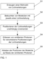
- Fig. 1 schematically shows a method for the parallelized determination of positions of two or more simultaneously active, spaced-apart molecules in one or more spatial directions in a sample.
- Light distributions resulting from interference of coherent light are used to determine the positions of the molecules.
- a plurality of light distributions is generated using a first light modulator with a plurality of switchable pixels S1.
- the first light modulator e.g. an amplitude modulator or a phase modulator
- a second light modulator is arranged in a Fourier plane to influence the light distributions, e.g. to block individual diffraction orders.
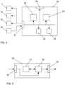
- control unit 22 can also control a second light modulator 12 arranged in a Fourier plane for influencing the light distributions, e.g., for blocking individual diffraction orders, and a light source 15.
- An evaluation unit 23 receives data from a detector unit 16 via the interface 21, with which photons emitted by the molecules are detected. Based on the photons emitted by the molecules for each of the light distributions for different positionings of the respective light distributions, the evaluation unit 23 derives the positions of the molecules.
- the switchable pixels of the first light modulator one-dimensional structures, e.g. grating structures, or two-dimensional structures, e.g. ring structures, are formed.
- the formed structures are then shifted.
- the shifts of the structures are preferably smaller than the dimensions of structural elements of the structures, whereby the dimensions of the structural elements in both dimensions are larger than the size of the pixels.
- the structural elements are the grating lines, and in the case of a ring structure, the ring.
- the light distributions can also result from a temporal superposition of different interference patterns of coherent light beams. For this purpose, for example, different diffraction orders of an interference pattern generated by the first light modulator can be caused to interfere in successive steps and the resulting interference patterns can be shifted relative to one another in the axial direction.
- an intensity curve of the light distribution is changed for successive positioning of a light distribution by changing a structural property of the associated one-dimensional or two-dimensional structure.
- the slope of the intensity increase regions adjacent to the local intensity minimum can be changed by changing a lattice constant of the one-dimensional structure or a hole diameter of the two-dimensional structure.
- the availability of multiple light distributions can be used to detect and compensate for sample drift.
- a marker in the sample can be detected using at least one light distribution.
- drift can be determined from concurrent changes in the measured positions of the molecules in consecutive measurements.
- the control unit 22 and the evaluation unit 23 can be controlled by a monitoring unit 24. Settings of the control unit 22, the evaluation unit 23, or the monitoring unit 24 can be changed via a user interface 26 if necessary.
- the data generated in the device 20 can be stored in a memory 25 of the device 20 if necessary, for example for later evaluation or for use by the components of the device 20.
- the control unit 22, the evaluation unit 23, and the monitoring unit 24 can be implemented as dedicated hardware, for example as integrated circuits. Of course, they can also be partially or completely combined or implemented as software running on a suitable processor, for example on a GPU or a CPU.
- the interface 21 can also be implemented in the form of separate inputs and outputs.
- the processor 32 may include one or more processor units, such as microprocessors, digital signal processors, or combinations thereof.
- the memories 25, 31 of the described embodiments can have both volatile and non-volatile memory areas and can comprise a wide variety of storage devices and storage media, for example hard disks, optical storage media or semiconductor memories.
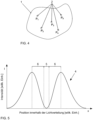
- Fig. 4 shows a sample 1 with a large number of molecules 2.
- Five molecules 2 are shown as examples, the positions P 1 to P 5 of which are to be determined.
- the molecules 2 are labeled with fluorophores or the molecules 2 are directly the fluorophores.
- the fluorophores can be excited to emit photons using light of a suitable wavelength.
- the fluorophores are excited in such a way that a fluorophore to be localized is always placed close to or in a minimum of a light distribution used for excitation, whereby the light distribution must have an intensity increase region adjacent to the minimum. This results in better utilization of the fluorescence photons with regard to obtaining information about the position of the respective emitting fluorophore.
- the minimum of the excitation light distribution is a zero.
- Fig. 5 shows an exemplary intensity profile across a cross section through a light distribution 4 suitable for the inventive solution.
- the intensity I is plotted against the position within the light distribution 4, here along the x-axis.
- the intensity profile of the light distribution 4 has a central intensity minimum 5, which is bordered on both sides by intensity increase regions 6.
- Such a light distribution 4 can be realized, for example, in the form of an intensity distribution in the shape of a donut.
- the central intensity minimum 5 is surrounded on all sides by intensity increase regions 6, so that direct position determination in two dimensions is possible.
- such a light distribution 4 can also be realized as an interference pattern of a stripe grating.
- the light distribution 4 has more than one intensity minimum 5, but only one of these is used.
- intensity increase regions 6 border the intensity minimum 5 only on two opposite sides, so that a correspondingly rotated stripe grating is required for position determination in two dimensions.
- position determination in three dimensions is also possible, provided the intensity distribution varies appropriately along the beam propagation direction.
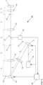
- Fig. 6 shows an exemplary basic structure of a microscope 40 in which a solution according to the invention is implemented.
- a light source 15, e.g. a laser emits coherent light 3, for example with a wavelength of 640 nm.
- the coherent light 3 strikes a first light modulator 7, which is arranged in an image plane 11 and has a multiplicity of switchable pixels, e.g. 1920 ⁇ 1080 or 2560 ⁇ 1600 pixels.
- a plurality of independently positionable light distributions can be generated by the switchable pixels forming one-dimensional or two-dimensional structures.
- the light emitted by the first light modulator 7 is imaged by a lens 14 into a Fourier plane 13 in which a second light modulator 12 is located.
- the second light modulator serves to influence the light distributions, for example by masking out individual diffraction orders.
- the light emitted by the second light modulator 12 is imaged into the sample by additional lenses 14, where it can be used to determine its position.
- Photons emitted by the molecules in sample 1 are directed toward a detector unit 16 via a beam splitter 17, e.g., a wavelength-selective beam splitter, and detected by the detector unit 16.
- the detector unit 16 can be a camera, e.g., with 2048 ⁇ 2048 pixels. Taking into account the Nyquist criterion for scanning, only 640 ⁇ 400 pixels are required for a field of view of 64 ⁇ m ⁇ 40 ⁇ m, enabling faster readout and also allowing the use of multiple wavelengths.
- the first light modulator 7, the second light modulator 12 and the light source 15 are controlled by a device 20 according to the invention for determining the positions of the molecules which also evaluates the data of the detector unit 16.
- a device 20 for determining the positions of the molecules which also evaluates the data of the detector unit 16.
- further components of the localization microscope 40 e.g. for influencing the polarization or a movement of the lenses 14 or the sample 1, are in Fig. 6 not shown. These are known to those skilled in the art and can also be controlled by the device 20.
- Fig. 6 The setup shown, in which the elements are located exactly in image planes 11 or in Fourier planes 13, is also possible. However, a setup in which both are only approximately fulfilled is also possible.
- the tolerable deviation in the axial direction scales with the Rayleigh lengths of the optics surrounding the elements, which, in turn, depends not only on the beam quality of the laser itself, but also on the focal length of the upstream optics, or, viewed from the direction of the object plane, on the downstream optics in the beam direction.
- the simplest way to achieve this is to place the second light modulator 12, which serves as a spatial filter, in a focal plane of the lens 14 after the first light modulator 7, and also to place the first light modulator 7 in an image plane to the object plane. Deviations from the ideal state at other locations can generally be more easily tolerated, but it is of course very simple to ideally construct the setup from lens 7 through the first lens 14 to the spatial filter 12.
- STED microscopes consist of a microscope stand with a built-in objective and an associated tube lens.
- the location of the (virtual) rear focal plane is known. In practice, this is often referred to as the pupil plane or simply the pupil.
- This plane is the plane to which the further optics must be referenced. This means that if collimated illumination is to be achieved in the object plane, the incident beam must be focused into this plane, which ultimately lies, or at least can lie, within the geometric dimensions of the objective. This means that it must be aligned so that, in the absence of the objective, it would form a focus at this point.
- this plane is the plane in which the field distribution should exist, the Fourier transform of which should be present in the object.
- a point source can be placed in this plane and imaged through the tube lens.
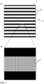
- Fig. 7 illustrates the realization of a structure 9 by means of a light modulator 7 with a plurality of pixels 8.
- Fig. 7a a structure 9 with a plurality of structural elements 10, in this case a striped grid.
- the structural elements 10 are therefore the individual grid lines.
- Fig. 7b shows an enlarged section of a single grating line.
- the grating line is made up of a large number of pixels 8 of the light modulator 7, i.e. the dimensions of the structural elements 10 are larger in both dimensions than the size of the pixels 8.
- the structures 9 realized by the light modulator 7 are shifted, i.e. the individual structural elements 10 are shifted here by integer multiples of the pixel size.
- the minimum shift of a structure in this binary light modulator 7 is predetermined by the pixel size and is therefore smaller than the dimensions of the structural elements 10.
- Subpixel shifts can be achieved, for example, by oblique patterns (aliasing effects), perforated patterns or multi-stage or analog modulators, if necessary in combination with additional Fourier filtering.
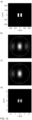
- Fig. 8 shows a first example of the generation of several independently positionable light distributions.
- Fig. 8a the structures realized with the first light modulator, in this case two stripe gratings with four grating lines each.
- Fig. 8b shows the corresponding interference pattern in the Fourier plane.
- the 0th order of the interference pattern is blocked by the second light modulator, which results in Fig. 8c ).
- the +1st order and the -1st order of the interference pattern interfere, which in the plane of the sample, ie the xy-plane, leads to the Fig. 8d ) interference patterns shown.
- the ⁇ 1st intensity minimum with the adjacent intensity maxima can be used, ie the 0th and the ⁇ 1st intensity maximum, which have approximately the same maximum intensity.
- Fig. 9 shows a second example for the generation of several independently positionable light distributions.
- Fig. 9a the structures realized with the first light modulator, in this case two stripe gratings with only two grating lines each. The lateral dimensions of the stripe gratings are smaller than in Fig. 8 example shown.
- Fig. 9b again shows the corresponding interference pattern in the Fourier plane. There, as before, the 0th order of the interference pattern is blocked by the second light modulator, which results in Fig. 9c ). In the further course, the +1st order and the -1st order of the interference pattern interfere, which in the plane of the sample leads to the Fig. 9d ) shown interference patterns.
- the ⁇ 1st intensity minimum with the adjacent 0th and ⁇ 1 intensity maxima can be used. Although these intensity maxima have different maximum intensities, the deviations do not affect the positioning accuracy.
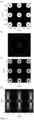
- Fig. 10 shows an example of how to create a light distribution in the form of a bottle beam.
- Fig. 10a the structure realized with the first light modulator, in this case a ring structure.
- Fig. 10b shows the corresponding situation in the Fourier plane.
- the Fig. 10c shown image.
- the central intensity minimum is surrounded on all sides by an intensity maximum.
- the Fig. 10d shows the intensity curve shown as a section in the xz plane.
- the light distribution also exhibits an intensity minimum in the axial direction, adjacent to regions of increasing intensity. The light distribution thus allows position determination in three dimensions.
- the sample can be moved in the axial direction, for example.
- an additional dynamically focusing element can be arranged in the beam path, with which the light distribution can be shifted in the axial direction, e.g., a deformable mirror.
- Fig. 11 shows an example of the generation of several independently positionable light distributions in the form of bottle beams.
- Fig. 11a the structure realized with the first light modulator, in this case nine independently positionable ring structures.
- Fig. 11b shows the corresponding situation in the Fourier plane.
- the Fig. 11c shown image.
- the central intensity minimum is surrounded on all sides by an intensity maximum.
- the Fig. 11d shows the intensity curve shown as a section in the xz plane.
- all light distributions also exhibit an intensity minimum in the axial direction, adjacent to which areas of intensity increase are located, thus enabling position determination in three dimensions.
- Fig. 12 shows an example of the generation of a light distribution by temporally superimposing different partial light distributions.
- Fig. 12a the structure realized with the first light modulator, in this case a stripe grating with two grating lines.
- Fig. 12b shows the corresponding interference pattern in the Fourier plane.
- the +1st order of the interference pattern is blocked by the second light modulator, which results in Fig. 12c ).
- the 0th order and the -1st order of the interference pattern interfere, which in the plane of the sample, ie the xy-plane, leads to the Fig. 12d ) shown partial light distribution.
- the result is a light distribution with an intensity minimum and adjacent Intensity maxima.
- the -1st order of the interference pattern is subsequently blocked by the second light modulator in the Fourier plane, so that the 0th order and the +1st order of the interference pattern interfere in the further course.
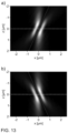
- the intensity distribution in the axial direction is interesting, which is Fig. 13 shown as a section in the xz-plane.
- Fig. 13a the intensity curve for the interference between 0th order -1st order of the interference pattern
- Fig. 13b the intensity curve for the interference between 0th order + 1st order of the interference pattern.
- the partial light distributions each have a tilted axis, which in Fig. 13a) and Fig. 13b ) is indicated by a dotted line. If the two partial light distributions are superimposed in time, ie they are radiated into the same position of the sample with a short time interval, the result is Fig. 14a ) is again shown as a section in the xz-plane. As can be clearly seen, the superimposed light distribution also has an intensity minimum in the axial direction, which is bordered by areas of intensity increase. As in Fig. 14b) and Fig. 14c ), this intensity minimum can be shifted in the axial direction by shifting the two partial light distributions relative to each other in the radial direction.
Landscapes
- Physics & Mathematics (AREA)
- Chemical & Material Sciences (AREA)
- General Physics & Mathematics (AREA)
- Analytical Chemistry (AREA)
- Health & Medical Sciences (AREA)
- Optics & Photonics (AREA)
- Immunology (AREA)
- Engineering & Computer Science (AREA)
- Multimedia (AREA)
- Nuclear Medicine, Radiotherapy & Molecular Imaging (AREA)
- Biochemistry (AREA)
- General Health & Medical Sciences (AREA)
- Pathology (AREA)
- Life Sciences & Earth Sciences (AREA)
- Computer Vision & Pattern Recognition (AREA)
- Chemical Kinetics & Catalysis (AREA)
- Investigating, Analyzing Materials By Fluorescence Or Luminescence (AREA)
- Microscoopes, Condenser (AREA)
Claims (15)
- Procédé pour la détermination parallélisée de positions (Pi) de deux ou plusieurs molécules (2) actives simultanément, séparées les unes des autres, dans une ou plusieurs directions spatiales dans un échantillon (1) au moyen d'un microscope de localisation (40), dans lequel, pour la détermination des positions (Pi) des molécules (2), on emploie des distributions de lumière (4) qui sont générées en raison d'interférences de lumière cohérente, avec les étapes :- création (S1) d'une multiplicité de distributions de lumière (4) moyennant l'emploi d'un premier modulateur de lumière (7) avec une multiplicité de pixels (8) commutables, qui est disposé dans un plan d'image (11) du microscope de localisation (40), dans lequel chaque distribution de lumière (4) présente un minimum d'intensité (5) local et des zones d'intensité croissante (6) lui étant adjacentes ;- éclairage (S2) de chacune des deux ou plusieurs molécules (2) avec respectivement une distribution de lumière (4) ;- pour chacune des distributions de lumière (4), détection (S4) de photons émis par les molécules (2) pour différentes positions de la distribution de lumière (4), dans lequel les distributions de lumière (4) sont positionnées (S3) de manière indépendante les unes des autres par un pilotage correspondant du premier modulateur de lumière (7) ; et- dérivation (S5) des positions (Pi) des molécules (2) sur la base des photons détectés pour les différents positionnements de la distribution de lumière (4).
- Procédé selon la revendication 1, dans lequel un deuxième modulateur de lumière (12) est disposé dans un plan de Fourier (13) du microscope de localisation (40) pour agir sur les distributions de lumière (4).
- Procédé selon la revendication 2, dans lequel le deuxième modulateur de lumière (12) est conçu pour bloquer des ordres de diffraction individuels.
- Procédé selon l'une des revendications précédentes, dans lequel le premier modulateur de lumière (7) est un modulateur d'amplitude ou un modulateur de phase, de préférence un modulateur d'amplitude ou un modulateur de phase commutable entre deux états fixes.
- Procédé selon l'une des revendications précédentes, dans lequel, pour la création (S1) des distributions de lumière (4) au moyen des pixels (8) commutables du premier modulateur de lumière (7), des structures (9) monodimensionnelles, de préférence des structures de grille, ou des structures (9) bidimensionnelles, de préférence des structures annulaires, sont formées.
- Procédé selon la revendication 5, dans lequel, pour le positionnement (S3) des distributions de lumière (4), les structures (9) formées au moyen des pixels (8) commutables du premier modulateur de lumière (7) sont déplacées.
- Procédé selon la revendication 6, dans lequel des déplacements des structures (9) sont plus petits que des dimensions d'éléments de structure (10) des structures (9), dans lequel les dimensions des éléments de structure (10) des structures (9) sont de préférence plus grandes dans les deux dimensions qu'une taille des pixels (8).
- Procédé selon l'une des revendications 5 à 7, dans lequel, pour des déterminations de positions successives avec une distribution de lumière (4), une évolution d'intensité de la distribution de lumière (4) est modifiée en ce qu'une propriété structurelle de la structure (9) monodimensionnelle ou bidimensionnelle correspondante est modifiée, dans lequel, de préférence une pente de flanc des zones d'intensité croissante (6) adjacentes du minimum d'intensité (5) local est modifiée en ce qu'une constante de grille, et/ou un rapport d'aspect de la structure monodimensionnelle, ou un diamètre de trou de la structure bidimensionnelle est modifié(e).
- Procédé selon l'une des revendications précédentes, dans lequel les distributions de lumière (4) résultent d'une superposition temporelle de différentes distributions partielles de lumière qui, de leur part, résultent de préférence de l'interférence de différents ordres de diffraction d'un motif d'interférence généré par le premier modulateur de lumière (7).
- Procédé selon l'une des revendications précédentes, dans lequel, au moyen d'au moins une distribution de lumière (4), un marqueur (6) est détecté dans l'échantillon (1) pour la détermination d'une dérive, et/ou dans lequel une dérive est déterminée à partir de modifications similaires des positions (Pi) de la molécule (2) mesurées dans des mesures successives.
- Procédé selon l'une des revendications précédentes, dans lequel les distributions de lumière (4) dans l'échantillon (1) présentent des dimensions latérales dans la plage de 0,5 µm à 4 µm.
- Procédé selon l'une des revendications précédentes, dans lequel les photons émis par les molécules (2) sont détectés (S4) avec une caméra ou un réseau de compteurs de photons.
- Programme informatique avec des instructions qui, lors de l'exécution par l'ordinateur font en sorte que l'ordinateur exécute les étapes d'un procédé selon l'une des revendications 1 à 12 pour la détermination parallélisée de positions (Pi) de deux ou plusieurs molécules (2) actives simultanément, séparées les unes des autres, dans une ou plusieurs directions spatiales dans un échantillon (1) au moyen d'un microscope de localisation (40).
- Dispositif (20) pour la détermination parallélisée de positions (Pi) de deux ou plusieurs molécules (2) actives simultanément, séparées les unes des autres, dans une ou plusieurs directions spatiales dans un échantillon (1) au moyen d'un microscope de localisation (40), dans lequel, pour la détermination des positions (Pi) des molécules (2), on emploie des distributions de lumière (4) qui sont générées en raison d'interférences de lumière cohérente, avec :- une unité de commande (22), qui est conçue pour la mise en œuvre d'un premier modulateur de lumière (7) avec une multiplicité de pixels (8) commutables qui est disposé dans un plan d'image (11) du microscope de localisation (40) pour la création (S1) d'une multiplicité de distributions de lumière (4) positionnables de manière indépendante les unes des autres par une mise en œuvre correspondante du premier modulateur de lumières (7), dans lequel chaque distribution de lumière (4) présente un minimum d'intensité (5) local et des zones d'intensité croissante (6) lui étant adjacentes ; et- une unité d'exploitation (23), qui est conçue pour la dérivation (S5) des positions (Pi) des molécules (2) sur la base de photons émis par les molécules (2) pour chacune des distributions de lumière (4) pour différents positionnements des distributions de lumière (4) respectives.
- Microscope (40), avec :- une source de lumière (15) pour la création de lumière cohérente (3) ;- un premier modulateur de lumière (7) avec une multiplicité de pixels (8) commutables, qui est disposé dans un plan d'image (11) du microscope (40), pour la création (S1) simultanée d'une multiplicité de distributions de lumière (4) qui sont générées en raison d'interférences de lumière cohérente, dans lequel chaque distribution de lumière (4) présente un minimum d'intensité (5) local et des zones d'intensité croissante (6) lui étant adjacentes ;- des moyens optiques (14) pour l'éclairage (S2) de deux ou plusieurs molécules (2) actives simultanément, séparées les unes des autres, dans un échantillon (1) avec respectivement une distribution de lumière (4) ;- une unité de détection (16) pour la détection (S4) de photons émis par les molécules (2) pour chacune des distributions de lumière (4) pour différents positionnements des distributions de lumière (4), dans lequel les distributions de lumière (4) sont positionnables de manière indépendante les unes des autres par une mise en œuvre correspondante du premier modulateur de lumière (7) ; et- un dispositif (20) selon la revendication 20 pour la détermination parallélisée de positions (Pi) des deux ou plusieurs molécules (2) dans une ou plusieurs directions spatiales.
Applications Claiming Priority (2)
| Application Number | Priority Date | Filing Date | Title |
|---|---|---|---|
| DE102020113998.5A DE102020113998A1 (de) | 2020-05-26 | 2020-05-26 | Verfahren, Computerprogramm und Vorrichtung zum Bestimmen von Positionen von Molekülen in einer Probe |
| PCT/EP2021/063788 WO2021239679A1 (fr) | 2020-05-26 | 2021-05-25 | Procédé, programme informatique, et dispositif de détermination de positions de molécules dans un échantillon |
Publications (2)
| Publication Number | Publication Date |
|---|---|
| EP4158317A1 EP4158317A1 (fr) | 2023-04-05 |
| EP4158317B1 true EP4158317B1 (fr) | 2025-04-09 |
Family
ID=76250292
Family Applications (1)
| Application Number | Title | Priority Date | Filing Date |
|---|---|---|---|
| EP21729434.7A Active EP4158317B1 (fr) | 2020-05-26 | 2021-05-25 | Procédé, programme informatique, et dispositif de détermination de positions de molécules dans un échantillon |
Country Status (5)
| Country | Link |
|---|---|
| US (1) | US12265033B2 (fr) |
| EP (1) | EP4158317B1 (fr) |
| CN (1) | CN115552223B (fr) |
| DE (1) | DE102020113998A1 (fr) |
| WO (1) | WO2021239679A1 (fr) |
Families Citing this family (6)
| Publication number | Priority date | Publication date | Assignee | Title |
|---|---|---|---|---|
| DE102020113998A1 (de) | 2020-05-26 | 2021-12-02 | Abberior Instruments Gmbh | Verfahren, Computerprogramm und Vorrichtung zum Bestimmen von Positionen von Molekülen in einer Probe |
| DE102020134495B4 (de) | 2020-12-21 | 2024-02-15 | Abberior Instruments Gmbh | Verfahren und Mikroskop zur Aufnahme von Trajektorien einzelner Partikel in einer Probe |
| DE102022119332B3 (de) | 2022-08-02 | 2023-12-28 | Abberior Instruments Gmbh | Verfahren, lichtmikroskop und computerprogramm zum lokalisieren oder verfolgen von emittern in einer probe |
| DE102022120952B4 (de) | 2022-08-18 | 2024-03-14 | Abberior Instruments Gmbh | Verfahren und vorrichtung zum simultanen verfolgen zweier emitter |
| DE102023119977A1 (de) | 2023-07-27 | 2025-01-30 | Abberior Instruments Gmbh | Verfahren, Computerprogramm und Vorrichtung zum Schätzen einer Lage eines Emitters in einer Probe |
| DE102023121626B4 (de) | 2023-08-11 | 2025-03-20 | Abberior Instruments Gmbh | Verfahren zum Lokalisieren und Verfolgen von Emittern in einer Probe |
Family Cites Families (33)
| Publication number | Priority date | Publication date | Assignee | Title |
|---|---|---|---|---|
| SU1374922A1 (ru) | 1986-04-10 | 1991-07-30 | Институт Биофизики Со Ан Ссср | Способ исследовани микроструктуры образца |
| DE10063276C2 (de) | 2000-12-19 | 2002-11-07 | Leica Microsystems | Scanmikroskop |
| JP2005084266A (ja) * | 2003-09-05 | 2005-03-31 | Kawasaki Heavy Ind Ltd | 光制御装置および光制御方法 |
| DE102006047912A1 (de) * | 2006-10-06 | 2008-04-10 | Carl Zeiss Microimaging Gmbh | Verfahren und Anordnung zur parallelisierten mikroskopischen Bildgebung |
| DE102007025688A1 (de) | 2007-06-01 | 2008-12-11 | MAX-PLANCK-Gesellschaft zur Förderung der Wissenschaften e.V. | Wellenlängen- oder polarisationssensitiver optischer Aufbau und dessen Verwendung |
| EP2389606B1 (fr) | 2009-01-24 | 2019-08-28 | Ecole Polytechnique Federale De Lausanne (EPFL) EPFL-TTO | Microscopie haute résolution et dispositifs de photolithographie utilisant des miroirs microscopiques de focalisation |
| US9523846B2 (en) | 2010-09-24 | 2016-12-20 | Carl Zeiss Microscopy Gmbh | 3D localisation microscopy and 4D localisation microscopy and tracking methods and systems |
| US9291562B2 (en) | 2011-11-15 | 2016-03-22 | Max-Planck-Gesellschaft Zur Foerderung Der Wissenschaften E.V. | Method and apparatus for tracking a particle, particularly a single molecule, in a sample |
| DE102011055367B4 (de) | 2011-11-15 | 2017-02-09 | MAX-PLANCK-Gesellschaft zur Förderung der Wissenschaften e.V. | Verfahren und Vorrichtung zum Verfolgen einer Bewegung eines Partikels, insbesondere eines einzelnen Moleküls, in einer Probe |
| GB201217171D0 (en) | 2012-08-23 | 2012-11-07 | Isis Innovation | Stimulated emission depletion microscopy |
| DE102013100172A1 (de) | 2013-01-09 | 2014-07-10 | MAX-PLANCK-Gesellschaft zur Förderung der Wissenschaften e.V. | Verfahren zum räumlich hochaufgelösten Abbilden einer einen Luminophor aufweisenden Struktur einer Probe |
| JP6276749B2 (ja) | 2013-03-06 | 2018-02-07 | 浜松ホトニクス株式会社 | 蛍光受光装置および蛍光受光方法 |
| EP2801854B1 (fr) | 2013-05-10 | 2017-07-19 | Ruprecht-Karls-Universität Heidelberg | Procédé et appareil de combinaison de microscopie de localisation et microscopie à éclairage structuré |
| DE102013114860B3 (de) * | 2013-12-23 | 2015-05-28 | MAX-PLANCK-Gesellschaft zur Förderung der Wissenschaften e.V. | Verfahren und Vorrichtung zur Bestimmung der Orte einzelner Moleküle einer Substanz in einer Probe |
| WO2016092161A1 (fr) * | 2014-12-09 | 2016-06-16 | Bioaxial Sas | Procédé et dispositif de mesure optique |
| DE202015001565U1 (de) | 2015-02-24 | 2015-10-15 | Erdmann Rainer / Picoquant Lnnovations Gmbh | Mikroskopische Vorrichtung mit Verfahren zur verbessertem Analyse von Photonendaten |
| US10884250B2 (en) | 2015-09-21 | 2021-01-05 | The Chinese University Of Hong Kong | Apparatus and method for laser beam shaping and scanning |
| US9632297B1 (en) | 2015-11-04 | 2017-04-25 | Abberior Instruments Gmbh | Device for separately modulating the wave fronts of two components of a light beam and microscope comprising the device |
| WO2017139885A1 (fr) | 2016-02-16 | 2017-08-24 | UNIVERSITé LAVAL | Procédé et système d'amélioration de résolution latérale de microscopie à balayage optique |
| EP3427036B2 (fr) * | 2016-03-07 | 2022-11-09 | Max-Planck-Gesellschaft zur Förderung der Wissenschaften e.V. | Procédé d'imagerie locale à haute résolution d'une structure dans un échantillon, afin de détecter des réactions d'un objet présentant un intérêt à des conditions environnementales modifiées |
| US11072160B2 (en) | 2016-08-23 | 2021-07-27 | Lawrence Livermore National Security, Llc | System and method for stimulated emission depletion projection stereolithography |
| DE102016119263B4 (de) * | 2016-10-10 | 2018-06-07 | MAX-PLANCK-Gesellschaft zur Förderung der Wissenschaften e.V. | Verfahren zum räumlich hochauflösenden Bestimmen des Orts eines vereinzelten, mit Anregungslicht zur Emission von Lumineszenzlicht anregbaren Moleküls in einer Probe |
| JP7048582B2 (ja) | 2016-10-10 | 2022-04-05 | マックス-プランク-ゲゼルシャフト ツア フェルデルング デア ヴィッセンシャフテン イー.ヴイ. | ルミネセンス光を放射するように励起光により励起可能な、試料中の分離された分子の位置を空間的に高分解能に確定するための方法 |
| CN108181235B (zh) * | 2017-11-18 | 2022-01-28 | 苏州国科医工科技发展(集团)有限公司 | 一种基于均匀结构光照明的sted并行显微成像系统 |
| EP3857284B1 (fr) * | 2018-09-27 | 2023-12-27 | Max-Planck-Gesellschaft zur Förderung der Wissenschaften e.V. | Procédé et appareil de formation et de décalage d'une répartition d'intensité lumineuse dans une zone focale d'une lentille d'objectif |
| DE102018127281A1 (de) | 2018-10-31 | 2020-04-30 | Carl Zeiss Microscopy Gmbh | Mikroskop und Verfahren zur Mikroskopie |
| CN110632045B (zh) | 2019-09-10 | 2022-05-20 | 之江实验室 | 一种产生并行超分辨焦斑的方法和装置 |
| NL2023860B1 (en) | 2019-09-19 | 2021-05-25 | Univ Delft Tech | Pattern activated structured illumination localization microscopy |
| CN111024658A (zh) * | 2019-11-27 | 2020-04-17 | 浙江大学 | 一种荧光分子定向定位方法和装置 |
| EP4070079A2 (fr) | 2019-12-02 | 2022-10-12 | Bioaxial SAS | Suivi dans l'obscurité, procédé hybride, microscopie à diffraction conique et adressage dans l'obscurité |
| CN111024664B (zh) * | 2019-12-18 | 2020-11-13 | 浙江大学 | 一种结构光照明超分辨显微芯片的成像方法 |
| DE102019135033A1 (de) * | 2019-12-19 | 2021-06-24 | Friedrich-Schiller-Universität Jena | Erzeugen eines Lichtfeldes mit mehreren lokalisierten Nullstellen |
| DE102020113998A1 (de) | 2020-05-26 | 2021-12-02 | Abberior Instruments Gmbh | Verfahren, Computerprogramm und Vorrichtung zum Bestimmen von Positionen von Molekülen in einer Probe |
-
2020
- 2020-05-26 DE DE102020113998.5A patent/DE102020113998A1/de active Pending
-
2021
- 2021-05-25 CN CN202180034359.9A patent/CN115552223B/zh active Active
- 2021-05-25 WO PCT/EP2021/063788 patent/WO2021239679A1/fr not_active Ceased
- 2021-05-25 EP EP21729434.7A patent/EP4158317B1/fr active Active
-
2022
- 2022-11-21 US US17/991,447 patent/US12265033B2/en active Active
Also Published As
| Publication number | Publication date |
|---|---|
| US12265033B2 (en) | 2025-04-01 |
| WO2021239679A1 (fr) | 2021-12-02 |
| CN115552223A (zh) | 2022-12-30 |
| EP4158317A1 (fr) | 2023-04-05 |
| CN115552223B (zh) | 2026-04-14 |
| US20230101017A1 (en) | 2023-03-30 |
| DE102020113998A1 (de) | 2021-12-02 |
Similar Documents
| Publication | Publication Date | Title |
|---|---|---|
| EP4158317B1 (fr) | Procédé, programme informatique, et dispositif de détermination de positions de molécules dans un échantillon | |
| EP2917776B1 (fr) | Microscope optique et procédé de microscopie | |
| DE102011055367B4 (de) | Verfahren und Vorrichtung zum Verfolgen einer Bewegung eines Partikels, insbesondere eines einzelnen Moleküls, in einer Probe | |
| EP2102695B1 (fr) | Procédé et dispositif de reproduction d'images microscopiques parallélisées | |
| DE112013002113B4 (de) | Strahlformer | |
| EP4158316B1 (fr) | Procédé et dispositif de détermination de position de molécules dans un échantillon | |
| EP2245494A1 (fr) | Dispositif et procédé de représentation tridimensionnelle à haute résolution d'une structure d'un échantillon | |
| DE19811202C2 (de) | Konfokales Scanmikroskop | |
| DE102011053232A1 (de) | Mikroskopische Einrichtung und mikroskopisches Verfahren zur dreidimensionalen Lokalisierung von punktförmigen Objekten | |
| EP3475750B1 (fr) | Dispositif d'éclairage pour un microscope | |
| DE102022119327B4 (de) | Verfahren, vorrichtung und computerprogramm zur lokalisierung vereinzelter emitter in einer probe | |
| WO2020114930A1 (fr) | Procédé et dispositif pour déceler des signaux de fluorescence dans une région tridimensionnelle d'un échantillon | |
| WO2009043545A1 (fr) | Procédé et dispositif de détection optique d'un échantillon éclairé | |
| EP4359771B1 (fr) | Procede, programme informatique et appareil d'estimation de la position d'un emetteur ou d'un reflecteur dans un echantillon | |
| DE102006026204A1 (de) | Mikroskop mit erhöhter Auflösung | |
| DE102012103459A1 (de) | Optisches abbildungs-oder bildgebungssystem mit strukturierter beleuchtung | |
| EP3482247B1 (fr) | Procédé d'analyse d'un échantillon et dispositif permettant la mise en oeuvre dudit procédé | |
| DE102023119101B3 (de) | MINFLUX- oder STED-MINFLUX-Mikroskop mit erhöhter zeitlich-örtlicher Auflösung und entsprechendes Verfahren | |
| EP3899502A1 (fr) | Microscopie à lumière fluorescente avec résolution axiale augmentée | |
| DE102018108657B4 (de) | Vorrichtung zur Aufnahme wenigstens eines mikroskopischen Bildes und Verfahren zur Aufnahme eines mikroskopischen Bildes | |
| WO2025022006A1 (fr) | Procédé, programme informatique, appareil et microscope pour estimer une position d'un émetteur dans un échantillon | |
| DE102009020320A1 (de) | Verfahren und Vorrichtung zur Steigerung der Auflösung und/oder der Geschwindigkeit von Belichtungssystemen | |
| DE10329756B4 (de) | Rastermikroskop mit einer Vorrichtung zur Fluoreszenz-Korrelations-Spektroskopie | |
| DE102024111213A1 (de) | Vorrichtung und Verfahren zum mikroskopischen Beleuchten einer Probe, Mikroskop und Verfahren zur Mikroskopie | |
| DE102024107201A1 (de) | Vorrichtung und Verfahren zum mikroskopischen optischen Manipulieren einer Probe, Mikroskop und Verfahren zur Mikroskopie |
Legal Events
| Date | Code | Title | Description |
|---|---|---|---|
| STAA | Information on the status of an ep patent application or granted ep patent |
Free format text: STATUS: UNKNOWN |
|
| STAA | Information on the status of an ep patent application or granted ep patent |
Free format text: STATUS: THE INTERNATIONAL PUBLICATION HAS BEEN MADE |
|
| PUAI | Public reference made under article 153(3) epc to a published international application that has entered the european phase |
Free format text: ORIGINAL CODE: 0009012 |
|
| STAA | Information on the status of an ep patent application or granted ep patent |
Free format text: STATUS: REQUEST FOR EXAMINATION WAS MADE |
|
| 17P | Request for examination filed |
Effective date: 20221212 |
|
| AK | Designated contracting states |
Kind code of ref document: A1 Designated state(s): AL AT BE BG CH CY CZ DE DK EE ES FI FR GB GR HR HU IE IS IT LI LT LU LV MC MK MT NL NO PL PT RO RS SE SI SK SM TR |
|
| DAV | Request for validation of the european patent (deleted) | ||
| DAX | Request for extension of the european patent (deleted) | ||
| STAA | Information on the status of an ep patent application or granted ep patent |
Free format text: STATUS: EXAMINATION IS IN PROGRESS |
|
| 17Q | First examination report despatched |
Effective date: 20240216 |
|
| RAP3 | Party data changed (applicant data changed or rights of an application transferred) |
Owner name: ABBERIOR INSTRUMENTS GMBH |
|
| GRAP | Despatch of communication of intention to grant a patent |
Free format text: ORIGINAL CODE: EPIDOSNIGR1 |
|
| STAA | Information on the status of an ep patent application or granted ep patent |
Free format text: STATUS: GRANT OF PATENT IS INTENDED |
|
| RIC1 | Information provided on ipc code assigned before grant |
Ipc: G02B 5/18 20060101ALI20241010BHEP Ipc: G02B 21/00 20060101ALI20241010BHEP Ipc: G02B 21/16 20060101ALI20241010BHEP Ipc: G01N 21/64 20060101AFI20241010BHEP |
|
| INTG | Intention to grant announced |
Effective date: 20241029 |
|
| GRAJ | Information related to disapproval of communication of intention to grant by the applicant or resumption of examination proceedings by the epo deleted |
Free format text: ORIGINAL CODE: EPIDOSDIGR1 |
|
| STAA | Information on the status of an ep patent application or granted ep patent |
Free format text: STATUS: EXAMINATION IS IN PROGRESS |
|
| INTC | Intention to grant announced (deleted) | ||
| GRAP | Despatch of communication of intention to grant a patent |
Free format text: ORIGINAL CODE: EPIDOSNIGR1 |
|
| STAA | Information on the status of an ep patent application or granted ep patent |
Free format text: STATUS: GRANT OF PATENT IS INTENDED |
|
| GRAS | Grant fee paid |
Free format text: ORIGINAL CODE: EPIDOSNIGR3 |
|
| GRAA | (expected) grant |
Free format text: ORIGINAL CODE: 0009210 |
|
| STAA | Information on the status of an ep patent application or granted ep patent |
Free format text: STATUS: THE PATENT HAS BEEN GRANTED |
|
| INTG | Intention to grant announced |
Effective date: 20250212 |
|
| AK | Designated contracting states |
Kind code of ref document: B1 Designated state(s): AL AT BE BG CH CY CZ DE DK EE ES FI FR GB GR HR HU IE IS IT LI LT LU LV MC MK MT NL NO PL PT RO RS SE SI SK SM TR |
|
| P01 | Opt-out of the competence of the unified patent court (upc) registered |
Free format text: CASE NUMBER: APP_10918/2025 Effective date: 20250305 |
|
| REG | Reference to a national code |
Ref country code: GB Ref legal event code: FG4D Free format text: NOT ENGLISH |
|
| REG | Reference to a national code |
Ref country code: CH Ref legal event code: EP |
|
| REG | Reference to a national code |
Ref country code: DE Ref legal event code: R096 Ref document number: 502021007177 Country of ref document: DE |
|
| REG | Reference to a national code |
Ref country code: IE Ref legal event code: FG4D Free format text: LANGUAGE OF EP DOCUMENT: GERMAN |
|
| PGFP | Annual fee paid to national office [announced via postgrant information from national office to epo] |
Ref country code: DE Payment date: 20250603 Year of fee payment: 5 |
|
| PGFP | Annual fee paid to national office [announced via postgrant information from national office to epo] |
Ref country code: GB Payment date: 20250528 Year of fee payment: 5 |
|
| PGFP | Annual fee paid to national office [announced via postgrant information from national office to epo] |
Ref country code: FR Payment date: 20250602 Year of fee payment: 5 |
|
| PGFP | Annual fee paid to national office [announced via postgrant information from national office to epo] |
Ref country code: AT Payment date: 20250721 Year of fee payment: 5 |
|
| REG | Reference to a national code |
Ref country code: NL Ref legal event code: MP Effective date: 20250409 |
|
| PG25 | Lapsed in a contracting state [announced via postgrant information from national office to epo] |
Ref country code: NL Free format text: LAPSE BECAUSE OF FAILURE TO SUBMIT A TRANSLATION OF THE DESCRIPTION OR TO PAY THE FEE WITHIN THE PRESCRIBED TIME-LIMIT Effective date: 20250409 |
|
| PG25 | Lapsed in a contracting state [announced via postgrant information from national office to epo] |
Ref country code: PT Free format text: LAPSE BECAUSE OF FAILURE TO SUBMIT A TRANSLATION OF THE DESCRIPTION OR TO PAY THE FEE WITHIN THE PRESCRIBED TIME-LIMIT Effective date: 20250811 Ref country code: FI Free format text: LAPSE BECAUSE OF FAILURE TO SUBMIT A TRANSLATION OF THE DESCRIPTION OR TO PAY THE FEE WITHIN THE PRESCRIBED TIME-LIMIT Effective date: 20250409 Ref country code: ES Free format text: LAPSE BECAUSE OF FAILURE TO SUBMIT A TRANSLATION OF THE DESCRIPTION OR TO PAY THE FEE WITHIN THE PRESCRIBED TIME-LIMIT Effective date: 20250409 |
|
| REG | Reference to a national code |
Ref country code: LT Ref legal event code: MG9D |
|
| PG25 | Lapsed in a contracting state [announced via postgrant information from national office to epo] |
Ref country code: NO Free format text: LAPSE BECAUSE OF FAILURE TO SUBMIT A TRANSLATION OF THE DESCRIPTION OR TO PAY THE FEE WITHIN THE PRESCRIBED TIME-LIMIT Effective date: 20250709 Ref country code: GR Free format text: LAPSE BECAUSE OF FAILURE TO SUBMIT A TRANSLATION OF THE DESCRIPTION OR TO PAY THE FEE WITHIN THE PRESCRIBED TIME-LIMIT Effective date: 20250710 |
|
| PG25 | Lapsed in a contracting state [announced via postgrant information from national office to epo] |
Ref country code: PL Free format text: LAPSE BECAUSE OF FAILURE TO SUBMIT A TRANSLATION OF THE DESCRIPTION OR TO PAY THE FEE WITHIN THE PRESCRIBED TIME-LIMIT Effective date: 20250409 |
|
| PG25 | Lapsed in a contracting state [announced via postgrant information from national office to epo] |
Ref country code: BG Free format text: LAPSE BECAUSE OF FAILURE TO SUBMIT A TRANSLATION OF THE DESCRIPTION OR TO PAY THE FEE WITHIN THE PRESCRIBED TIME-LIMIT Effective date: 20250409 |
|
| PG25 | Lapsed in a contracting state [announced via postgrant information from national office to epo] |
Ref country code: HR Free format text: LAPSE BECAUSE OF FAILURE TO SUBMIT A TRANSLATION OF THE DESCRIPTION OR TO PAY THE FEE WITHIN THE PRESCRIBED TIME-LIMIT Effective date: 20250409 |
|
| PG25 | Lapsed in a contracting state [announced via postgrant information from national office to epo] |
Ref country code: RS Free format text: LAPSE BECAUSE OF FAILURE TO SUBMIT A TRANSLATION OF THE DESCRIPTION OR TO PAY THE FEE WITHIN THE PRESCRIBED TIME-LIMIT Effective date: 20250709 |
|
| PG25 | Lapsed in a contracting state [announced via postgrant information from national office to epo] |
Ref country code: IS Free format text: LAPSE BECAUSE OF FAILURE TO SUBMIT A TRANSLATION OF THE DESCRIPTION OR TO PAY THE FEE WITHIN THE PRESCRIBED TIME-LIMIT Effective date: 20250809 |
|
| PG25 | Lapsed in a contracting state [announced via postgrant information from national office to epo] |
Ref country code: LV Free format text: LAPSE BECAUSE OF FAILURE TO SUBMIT A TRANSLATION OF THE DESCRIPTION OR TO PAY THE FEE WITHIN THE PRESCRIBED TIME-LIMIT Effective date: 20250409 |
|
| REG | Reference to a national code |
Ref country code: CH Ref legal event code: H13 Free format text: ST27 STATUS EVENT CODE: U-0-0-H10-H13 (AS PROVIDED BY THE NATIONAL OFFICE) Effective date: 20251223 |
|
| REG | Reference to a national code |
Ref country code: DE Ref legal event code: R097 Ref document number: 502021007177 Country of ref document: DE |
|
| PG25 | Lapsed in a contracting state [announced via postgrant information from national office to epo] |
Ref country code: SM Free format text: LAPSE BECAUSE OF FAILURE TO SUBMIT A TRANSLATION OF THE DESCRIPTION OR TO PAY THE FEE WITHIN THE PRESCRIBED TIME-LIMIT Effective date: 20250409 Ref country code: DK Free format text: LAPSE BECAUSE OF FAILURE TO SUBMIT A TRANSLATION OF THE DESCRIPTION OR TO PAY THE FEE WITHIN THE PRESCRIBED TIME-LIMIT Effective date: 20250409 |
|
| PG25 | Lapsed in a contracting state [announced via postgrant information from national office to epo] |
Ref country code: LU Free format text: LAPSE BECAUSE OF NON-PAYMENT OF DUE FEES Effective date: 20250525 |
|
| PG25 | Lapsed in a contracting state [announced via postgrant information from national office to epo] |
Ref country code: CH Free format text: LAPSE BECAUSE OF NON-PAYMENT OF DUE FEES Effective date: 20250531 |
|
| PG25 | Lapsed in a contracting state [announced via postgrant information from national office to epo] |
Ref country code: CZ Free format text: LAPSE BECAUSE OF FAILURE TO SUBMIT A TRANSLATION OF THE DESCRIPTION OR TO PAY THE FEE WITHIN THE PRESCRIBED TIME-LIMIT Effective date: 20250409 |
|
| PG25 | Lapsed in a contracting state [announced via postgrant information from national office to epo] |
Ref country code: EE Free format text: LAPSE BECAUSE OF FAILURE TO SUBMIT A TRANSLATION OF THE DESCRIPTION OR TO PAY THE FEE WITHIN THE PRESCRIBED TIME-LIMIT Effective date: 20250409 |
|
| PG25 | Lapsed in a contracting state [announced via postgrant information from national office to epo] |
Ref country code: SK Free format text: LAPSE BECAUSE OF FAILURE TO SUBMIT A TRANSLATION OF THE DESCRIPTION OR TO PAY THE FEE WITHIN THE PRESCRIBED TIME-LIMIT Effective date: 20250409 |
|
| PG25 | Lapsed in a contracting state [announced via postgrant information from national office to epo] |
Ref country code: IT Free format text: LAPSE BECAUSE OF FAILURE TO SUBMIT A TRANSLATION OF THE DESCRIPTION OR TO PAY THE FEE WITHIN THE PRESCRIBED TIME-LIMIT Effective date: 20250409 |
|
| REG | Reference to a national code |
Ref country code: BE Ref legal event code: MM Effective date: 20250531 |
|
| PG25 | Lapsed in a contracting state [announced via postgrant information from national office to epo] |
Ref country code: MC Free format text: LAPSE BECAUSE OF FAILURE TO SUBMIT A TRANSLATION OF THE DESCRIPTION OR TO PAY THE FEE WITHIN THE PRESCRIBED TIME-LIMIT Effective date: 20250409 |
|
| PG25 | Lapsed in a contracting state [announced via postgrant information from national office to epo] |
Ref country code: RO Free format text: LAPSE BECAUSE OF FAILURE TO SUBMIT A TRANSLATION OF THE DESCRIPTION OR TO PAY THE FEE WITHIN THE PRESCRIBED TIME-LIMIT Effective date: 20250409 |
|
| PLBE | No opposition filed within time limit |
Free format text: ORIGINAL CODE: 0009261 |
|
| STAA | Information on the status of an ep patent application or granted ep patent |
Free format text: STATUS: NO OPPOSITION FILED WITHIN TIME LIMIT |
|
| REG | Reference to a national code |
Ref country code: CH Ref legal event code: L10 Free format text: ST27 STATUS EVENT CODE: U-0-0-L10-L00 (AS PROVIDED BY THE NATIONAL OFFICE) Effective date: 20260218 |
|
| 26N | No opposition filed |
Effective date: 20260112 |
|
| PG25 | Lapsed in a contracting state [announced via postgrant information from national office to epo] |
Ref country code: IE Free format text: LAPSE BECAUSE OF NON-PAYMENT OF DUE FEES Effective date: 20250525 |
|
| PG25 | Lapsed in a contracting state [announced via postgrant information from national office to epo] |
Ref country code: BE Free format text: LAPSE BECAUSE OF NON-PAYMENT OF DUE FEES Effective date: 20250531 |