EP4158317B1 - Method, computer program, and device for determining positions of molecules in a sample - Google Patents
Method, computer program, and device for determining positions of molecules in a sample Download PDFInfo
- Publication number
- EP4158317B1 EP4158317B1 EP21729434.7A EP21729434A EP4158317B1 EP 4158317 B1 EP4158317 B1 EP 4158317B1 EP 21729434 A EP21729434 A EP 21729434A EP 4158317 B1 EP4158317 B1 EP 4158317B1
- Authority
- EP
- European Patent Office
- Prior art keywords
- light
- molecules
- distributions
- modulator
- light distributions
- Prior art date
- Legal status (The legal status is an assumption and is not a legal conclusion. Google has not performed a legal analysis and makes no representation as to the accuracy of the status listed.)
- Active
Links
Images


Classifications
-
- G—PHYSICS
- G02—OPTICS
- G02B—OPTICAL ELEMENTS, SYSTEMS OR APPARATUS
- G02B21/00—Microscopes
- G02B21/0004—Microscopes specially adapted for specific applications
- G02B21/002—Scanning microscopes
- G02B21/0024—Confocal scanning microscopes (CSOMs) or confocal "macroscopes"; Accessories which are not restricted to use with CSOMs, e.g. sample holders
- G02B21/0036—Scanning details, e.g. scanning stages
- G02B21/004—Scanning details, e.g. scanning stages fixed arrays, e.g. switchable aperture arrays
-
- G—PHYSICS
- G01—MEASURING; TESTING
- G01N—INVESTIGATING OR ANALYSING MATERIALS BY DETERMINING THEIR CHEMICAL OR PHYSICAL PROPERTIES
- G01N21/00—Investigating or analysing materials by the use of optical means, i.e. using sub-millimetre waves, infrared, visible or ultraviolet light
- G01N21/62—Systems in which the material investigated is excited whereby it emits light or causes a change in wavelength of the incident light
- G01N21/63—Systems in which the material investigated is excited whereby it emits light or causes a change in wavelength of the incident light optically excited
- G01N21/64—Fluorescence; Phosphorescence
- G01N21/6428—Measuring fluorescence of fluorescent products of reactions or of fluorochrome labelled reactive substances, e.g. measuring quenching effects, using measuring "optrodes"
-
- G—PHYSICS
- G01—MEASURING; TESTING
- G01N—INVESTIGATING OR ANALYSING MATERIALS BY DETERMINING THEIR CHEMICAL OR PHYSICAL PROPERTIES
- G01N21/00—Investigating or analysing materials by the use of optical means, i.e. using sub-millimetre waves, infrared, visible or ultraviolet light
- G01N21/62—Systems in which the material investigated is excited whereby it emits light or causes a change in wavelength of the incident light
- G01N21/63—Systems in which the material investigated is excited whereby it emits light or causes a change in wavelength of the incident light optically excited
- G01N21/64—Fluorescence; Phosphorescence
- G01N21/645—Specially adapted constructive features of fluorimeters
- G01N21/6456—Spatial resolved fluorescence measurements; Imaging
- G01N21/6458—Fluorescence microscopy
-
- G—PHYSICS
- G02—OPTICS
- G02B—OPTICAL ELEMENTS, SYSTEMS OR APPARATUS
- G02B21/00—Microscopes
- G02B21/0004—Microscopes specially adapted for specific applications
- G02B21/002—Scanning microscopes
- G02B21/0024—Confocal scanning microscopes (CSOMs) or confocal "macroscopes"; Accessories which are not restricted to use with CSOMs, e.g. sample holders
- G02B21/0052—Optical details of the image generation
- G02B21/0076—Optical details of the image generation arrangements using fluorescence or luminescence
-
- G—PHYSICS
- G02—OPTICS
- G02B—OPTICAL ELEMENTS, SYSTEMS OR APPARATUS
- G02B21/00—Microscopes
- G02B21/16—Microscopes adapted for ultraviolet illumination ; Fluorescence microscopes
-
- G—PHYSICS
- G02—OPTICS
- G02B—OPTICAL ELEMENTS, SYSTEMS OR APPARATUS
- G02B21/00—Microscopes
- G02B21/36—Microscopes arranged for photographic purposes or projection purposes or digital imaging or video purposes including associated control and data processing arrangements
- G02B21/361—Optical details, e.g. image relay to the camera or image sensor
-
- G—PHYSICS
- G02—OPTICS
- G02B—OPTICAL ELEMENTS, SYSTEMS OR APPARATUS
- G02B21/00—Microscopes
- G02B21/36—Microscopes arranged for photographic purposes or projection purposes or digital imaging or video purposes including associated control and data processing arrangements
- G02B21/365—Control or image processing arrangements for digital or video microscopes
-
- G—PHYSICS
- G02—OPTICS
- G02B—OPTICAL ELEMENTS, SYSTEMS OR APPARATUS
- G02B5/00—Optical elements other than lenses
- G02B5/18—Diffraction gratings
- G02B5/1809—Diffraction gratings with pitch less than or comparable to the wavelength
Definitions
- the present invention relates to a method, a computer program with instructions, and a device for the parallel determination of positions of molecules in a sample.
- the present invention relates to a method, a computer program with instructions, and a device for the parallel determination of positions of two or more simultaneously active, spaced-apart molecules in one or more spatial directions in a sample using a localization microscope, wherein light distributions resulting from interference of coherent light are used to determine the positions of the molecules.
- the present invention also relates to a localization microscope that uses a device according to the invention.
- MINFLUX microscopy is a technical implementation of localization microscopy.
- the localization of fluorophores in a sample is achieved using structured excitation light distributions.
- the term MINFLUX is derived from the underlying concept of determining the coordinates of a molecule using a minimal number of fluorescence photons (MINimal emission FLUXes).
- MINFLUXes minimal number of fluorescence photons
- the fundamental characteristic of MINFLUX microscopy is that the excitation of the fluorophores occurs in such a way that the fluorophore to be localized is always positioned close to or within a minimum of the excitation light distribution, which ideally is a zero point.
- the excitation light distribution must exhibit an intensity increase region adjacent to the minimum.
- DE 10 2011 055 367 B4 describes a method for tracking the movement of a particle in a sample.
- the particle is induced to emit photons using light, and the photons emitted by the particle are recorded.
- the light is directed onto the sample with an intensity distribution exhibiting a spatially limited minimum.
- the minimum is assigned to the particle moving within the sample. by shifting the intensity distribution relative to the sample so that the rate of photons emitted by the particle remains minimal.
- DE 10 2013 114 860 B3 Describes a method for determining the locations of individual molecules of a substance in a sample.
- the individual molecules are in a fluorescent state and are excited by excitation light to emit fluorescent light, with an intensity distribution of the excitation light having at least one zero.
- the fluorescent light from the excited individual molecules is recorded for various positions of the at least one zero of the intensity distribution of the excitation light.
- the locations of the individual molecules are then derived from the course of the intensity of the fluorescent light over the positions of the at least one zero of the intensity distribution of the excitation light.
- the emission rate increases the further the fluorophore is from the excitation minimum or the further the fluorophore is shifted into a region of intensity increase.
- This more precisely determined position can now be used as the starting position for repeating the sequence of the aforementioned steps, whereby the positions can be placed closer to the estimated position of the fluorophore.
- the change in the emission rate when the fluorophore is shifted into the region of intensity increase or towards the minimum can also be used to estimate the displacement of the fluorophore.
- US 2019/0235220 A1 Describes a method for determining the position of the fluorophore, requiring only a small or minimal number of positions at which an intensity minimum is placed.
- the intensity minimum is adjacent to regions of intensity increase in each spatial direction in which a fluorophore position is to be determined.
- US 2019/0234882 A1 describes a method in which the spatial information obtained from a first MINFLUX step is used to place the minimum of the intensity light distribution closer to the fluorophore in a subsequent step and to derive more precise spatial information from this.
- US 2019/0234879 A1 describes a method in which the intensity minimum is very quickly placed at a number of positions around the estimated position of the fluorophore. A single position is then moved closer to the presumed minimum if an increased emission rate is detected at that position. Such a method is particularly suitable for observing the movement of fluorophores.
- the position of fluorophores in two spatial directions could be determined experimentally with an uncertainty of only 1 nm, ie the accuracy of the position determination is comparable to the extent of the fluorophores themselves. If the position of a single fluorophore can be determined with a given measurement uncertainty, this requires less time than determining its position using conventional localization microscopy.
- a disadvantage of MINFLUX microscopy is that determining the position of a large number of fluorophores has been very time-consuming.
- SIM Structured Illumination Microscopy
- ROSE Repetitive Optical Selective Exposure
- CCD charge-coupled device
- the arrangement of the light modulator in an image plane has the advantage that shifting the light distributions in the sample by directly imaging structures or patterns on the light modulator in the image plane is particularly easy and therefore quick to achieve: Individually shifting the light distributions corresponds to individually shifting the patterns on the light modulator. The required shift can be calculated very quickly, resulting in high decision speed.
- a second light modulator is arranged in a Fourier plane of the localization microscope to influence the light distributions.
- the second light modulator is configured to block individual diffraction orders.
- the second light modulator can further influence the light distributions generated by the first light modulator in a targeted manner. If, for example, the first light modulator generates multiple diffraction orders, the second light modulator can filter out those diffraction orders that are not to be used in the further beam path. The filtering can be adapted to the situation, thus achieving great flexibility.
- the first light modulator is an amplitude modulator or a phase modulator.
- the first light modulator is a light modulator that can be switched between two fixed states.
- Binary light modulators have the advantage of being very fast, whereas analog phase modulators, as typically used in holographic approaches, are significantly slower.
- the light modulator can be implemented, for example, as a liquid crystal modulator or as a micro-electromechanical modulator, in particular as a micromirror array.
- Such light modulators are commercially available, easy to implement, and enable frame rates of 30 kHz to 50 kHz. It is expected that even higher frame rates will be achieved in the future. For example, a light modulator with 1920 ⁇ 1080 or 2560 ⁇ 1600 switchable pixels can be used.
- one-dimensional or two-dimensional Structures are formed.
- the one-dimensional structures are grating structures
- the two-dimensional structures are ring structures.
- Each one-dimensional grating structure creates a grating-like light distribution in the sample consisting of successive intensity maxima and intensity minima, which can be used to determine the position of, for example, a fluorophore in one spatial direction.
- the central intensity maximum and one of the two adjacent intensity maxima, or the two brightest intensity maxima with the intensity minimum located between the selected maxima can be used.
- a light distribution of a different orientation must also be provided.
- the ring structures can create a light distribution in the form of a so-called "bottle beam,” i.e., a light distribution that has a zero point limited in three spatial directions and with which position determination in three spatial directions is possible.
- a donut i.e., light distributions that have a zero point limited in two spatial directions and with which position determination in two spatial directions is possible.
- dots or discs can be displayed on the first light modulator.
- a static or dynamic phase modulator as known from STED microscopy, is used to impose a phase ramp.
- the structures formed by the switchable pixels of the first light modulator are shifted to position the light distributions.
- the shifts of the structures are preferably smaller than the dimensions of structural elements of the structures, wherein the dimensions of the structural elements are larger in both dimensions than the size of the pixels.
- a grating line formed with the pixels can have a line width of ten pixels. If the optical system is configured such that this results in a period of the light distribution in the sample of 250 nm, a shift of the grating lines by one pixel leads to a shift of the light distribution in the sample of 25 nm.
- an intensity profile of the light distribution is changed by changing a structural property of the associated one-dimensional or two-dimensional structure. For example, a slope of the intensity increase regions adjacent to the local intensity minimum can be changed by changing a lattice constant and/or an aspect ratio of the one-dimensional structure or a hole diameter of the two-dimensional structure.
- the light distributions result from a temporal superposition of different partial light distributions.
- different diffraction orders of an interference pattern generated by the first light modulator can be caused to interfere in successive steps, resulting in a partial light distribution that has a tilted axis, so to speak.
- the direction of the tilt depends on which diffraction orders are interfering. If the resulting partial light distributions are temporally superimposed, a three-dimensional accumulated light distribution is created that has a minimum in the axial direction at the position of the intersection of the tilted axes, adjacent to which regions of intensity increase are located.
- a marker in the sample is detected using at least one light distribution to determine drift.
- drift can be determined from consistent changes in the measured positions of the molecules in successive measurements.
- a bottle beam can be used, for example, to bleach a bead from a colored structure, e.g., fibers in a fixed cell that are colored with a non-switchable fluorophore. If a specific location is illuminated for a while, the fiber is bleached around a point. In this way, a permanently luminous A spot can be generated.
- This spot can, for example, have a size of 40 nm to 100 nm and can then be gently localized using the MINFLUX principle.
- the co-directional movement of a large number of molecules can be used to determine that a relative displacement has occurred between the sample and the measurement setup. The measured movements of the individual molecules can then be corrected for the co-directional component of the movement.
- the light distributions in the sample have lateral dimensions in the range of 0.5 ⁇ m to 4 ⁇ m. It has been shown that these dimensions of the light distributions in the sample allow for reliable position determinations and, at the same time, a large number of independently positionable light distributions can be realized.
- the estimation of the positions of the active luminophores or fluorophores, which precedes the application of localization according to the MINFLUX principle can be performed by generating a sequence of one-dimensional grid-shaped illumination light distributions, preferably using the first light modulator, wherein each illumination light distribution of the sequence extends over the same plurality of individual fluorophores.
- the positions of the multiple fluorophores can preferably be estimated using a method known from the prior art as SIMPLE, SIMFLUX, or ROSE. Subsequently, the more precise localization is performed simultaneously for a plurality of the multiple fluorophores or for all fluorophores, each according to the MINFLUX principle.
- fluorophores can first be specifically rendered fluorescent in specific areas using a light distribution of a suitable wavelength and suitable projected patterns, or can be specifically left fluorescent in specific areas.
- the light distribution can be a point grating overall or in sections.
- continuous planar illumination patterns with continuously varying accumulated light intensity are possible, e.g., by using a DMD in grayscale mode, which are adapted to the density distribution of the observed structure, so that a desired density distribution of activated molecules can be specifically generated.
- the same light modulator in an image plane can preferably be used for activation as for the subsequent excitation.
- a sequence or combination of different light distributions can also be used, for example, a sequence of a pattern of activation light with an intensity distribution adjusted so that inactive fluorophores are switched to an active state with a suitable probability in areas of intensity maxima, and a corresponding pattern of deactivation light, which has zero points in areas of the intensity maxima of the activation light, thus leaving fluorophores in the active state there.
- Adjusting the activation light such that only a suitable, small amount of fluorophores is activated is generally known to those skilled in the art.
- the MINFLUX principle can then be used in parallel in the areas prepared in this way.
- a combination of an excitation light distribution and a deactivation light distribution can also be advantageously used, where the deactivation light is STED light.
- the deactivation light is STED light.
- the light distributions do not have to correspond completely.
- a donut can be selected as the STED light distribution and a one-dimensional grating as the excitation light distribution.
- the excitation light distributions and the STED light distributions can be repositioned simultaneously, i.e.
- the excitation light distributions can be repositioned while the STED light distributions remain stationary, so that excitation minima are positioned several times differently within a range of a STED minimum, or the excitation light distributions can be left stationary and the STED light distributions repositioned. Combinations of the three variants mentioned are also conceivable. Alternatively, or in addition to the repositioning, the dimensions and/or intensities of the light distributions of the excitation and/or STED light can also be changed.
- STED donuts with a spatially more extended minimum can be overlaid with excitation light distributions at the beginning, and in the following steps, these STED donuts, for example, can be narrowed depending on the localization accuracy already achieved and/or their intensity can be increased.
- a light modulator is preferably used for each light type to generate the light distributions of the two light types.
- Each light type is arranged in an image plane within a corresponding excitation or STED light path.
- the light paths can be combined, viewed in the direction of the light paths, for example, using a beam combiner, which can be a dichroic component.
- the STED light distributions exhibit local minima, but not the excitation light distributions.
- the MINFLUX principle is not implemented, but the positions of the molecules to be localized are nevertheless determined based on the photons detected for the various positioning of the light distributions, preferably using a ratiometric method.
- luminophores or fluorophores that can be put into a protective state can be used.
- Such luminophores and their use in a special STED method are known, for example, from WO 2014 108455 A1 known.
- the luminophores are in a protected state in which they are neither bleached by the excitation nor by the STED light.
- STED light prevents a fluorophore adjacent to a fluorophore in the group from accidentally switching to an excitable state during the localization of a single group of fluorophores and disrupting or preventing the localization of that fluorophore.
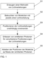
- Fig. 1 schematically shows a method for the parallelized determination of positions of two or more simultaneously active, spaced-apart molecules in one or more spatial directions in a sample.
- Light distributions resulting from interference of coherent light are used to determine the positions of the molecules.
- a plurality of light distributions is generated using a first light modulator with a plurality of switchable pixels S1.
- the first light modulator e.g. an amplitude modulator or a phase modulator
- a second light modulator is arranged in a Fourier plane to influence the light distributions, e.g. to block individual diffraction orders.
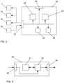
- control unit 22 can also control a second light modulator 12 arranged in a Fourier plane for influencing the light distributions, e.g., for blocking individual diffraction orders, and a light source 15.
- An evaluation unit 23 receives data from a detector unit 16 via the interface 21, with which photons emitted by the molecules are detected. Based on the photons emitted by the molecules for each of the light distributions for different positionings of the respective light distributions, the evaluation unit 23 derives the positions of the molecules.
- the switchable pixels of the first light modulator one-dimensional structures, e.g. grating structures, or two-dimensional structures, e.g. ring structures, are formed.
- the formed structures are then shifted.
- the shifts of the structures are preferably smaller than the dimensions of structural elements of the structures, whereby the dimensions of the structural elements in both dimensions are larger than the size of the pixels.
- the structural elements are the grating lines, and in the case of a ring structure, the ring.
- the light distributions can also result from a temporal superposition of different interference patterns of coherent light beams. For this purpose, for example, different diffraction orders of an interference pattern generated by the first light modulator can be caused to interfere in successive steps and the resulting interference patterns can be shifted relative to one another in the axial direction.
- an intensity curve of the light distribution is changed for successive positioning of a light distribution by changing a structural property of the associated one-dimensional or two-dimensional structure.
- the slope of the intensity increase regions adjacent to the local intensity minimum can be changed by changing a lattice constant of the one-dimensional structure or a hole diameter of the two-dimensional structure.
- the availability of multiple light distributions can be used to detect and compensate for sample drift.
- a marker in the sample can be detected using at least one light distribution.
- drift can be determined from concurrent changes in the measured positions of the molecules in consecutive measurements.
- the control unit 22 and the evaluation unit 23 can be controlled by a monitoring unit 24. Settings of the control unit 22, the evaluation unit 23, or the monitoring unit 24 can be changed via a user interface 26 if necessary.
- the data generated in the device 20 can be stored in a memory 25 of the device 20 if necessary, for example for later evaluation or for use by the components of the device 20.
- the control unit 22, the evaluation unit 23, and the monitoring unit 24 can be implemented as dedicated hardware, for example as integrated circuits. Of course, they can also be partially or completely combined or implemented as software running on a suitable processor, for example on a GPU or a CPU.
- the interface 21 can also be implemented in the form of separate inputs and outputs.
- the processor 32 may include one or more processor units, such as microprocessors, digital signal processors, or combinations thereof.
- the memories 25, 31 of the described embodiments can have both volatile and non-volatile memory areas and can comprise a wide variety of storage devices and storage media, for example hard disks, optical storage media or semiconductor memories.
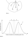
- Fig. 4 shows a sample 1 with a large number of molecules 2.
- Five molecules 2 are shown as examples, the positions P 1 to P 5 of which are to be determined.
- the molecules 2 are labeled with fluorophores or the molecules 2 are directly the fluorophores.
- the fluorophores can be excited to emit photons using light of a suitable wavelength.
- the fluorophores are excited in such a way that a fluorophore to be localized is always placed close to or in a minimum of a light distribution used for excitation, whereby the light distribution must have an intensity increase region adjacent to the minimum. This results in better utilization of the fluorescence photons with regard to obtaining information about the position of the respective emitting fluorophore.
- the minimum of the excitation light distribution is a zero.
- Fig. 5 shows an exemplary intensity profile across a cross section through a light distribution 4 suitable for the inventive solution.
- the intensity I is plotted against the position within the light distribution 4, here along the x-axis.
- the intensity profile of the light distribution 4 has a central intensity minimum 5, which is bordered on both sides by intensity increase regions 6.
- Such a light distribution 4 can be realized, for example, in the form of an intensity distribution in the shape of a donut.
- the central intensity minimum 5 is surrounded on all sides by intensity increase regions 6, so that direct position determination in two dimensions is possible.
- such a light distribution 4 can also be realized as an interference pattern of a stripe grating.
- the light distribution 4 has more than one intensity minimum 5, but only one of these is used.
- intensity increase regions 6 border the intensity minimum 5 only on two opposite sides, so that a correspondingly rotated stripe grating is required for position determination in two dimensions.
- position determination in three dimensions is also possible, provided the intensity distribution varies appropriately along the beam propagation direction.
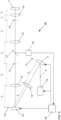
- Fig. 6 shows an exemplary basic structure of a microscope 40 in which a solution according to the invention is implemented.
- a light source 15, e.g. a laser emits coherent light 3, for example with a wavelength of 640 nm.
- the coherent light 3 strikes a first light modulator 7, which is arranged in an image plane 11 and has a multiplicity of switchable pixels, e.g. 1920 ⁇ 1080 or 2560 ⁇ 1600 pixels.
- a plurality of independently positionable light distributions can be generated by the switchable pixels forming one-dimensional or two-dimensional structures.
- the light emitted by the first light modulator 7 is imaged by a lens 14 into a Fourier plane 13 in which a second light modulator 12 is located.
- the second light modulator serves to influence the light distributions, for example by masking out individual diffraction orders.
- the light emitted by the second light modulator 12 is imaged into the sample by additional lenses 14, where it can be used to determine its position.
- Photons emitted by the molecules in sample 1 are directed toward a detector unit 16 via a beam splitter 17, e.g., a wavelength-selective beam splitter, and detected by the detector unit 16.
- the detector unit 16 can be a camera, e.g., with 2048 ⁇ 2048 pixels. Taking into account the Nyquist criterion for scanning, only 640 ⁇ 400 pixels are required for a field of view of 64 ⁇ m ⁇ 40 ⁇ m, enabling faster readout and also allowing the use of multiple wavelengths.
- the first light modulator 7, the second light modulator 12 and the light source 15 are controlled by a device 20 according to the invention for determining the positions of the molecules which also evaluates the data of the detector unit 16.
- a device 20 for determining the positions of the molecules which also evaluates the data of the detector unit 16.
- further components of the localization microscope 40 e.g. for influencing the polarization or a movement of the lenses 14 or the sample 1, are in Fig. 6 not shown. These are known to those skilled in the art and can also be controlled by the device 20.
- Fig. 6 The setup shown, in which the elements are located exactly in image planes 11 or in Fourier planes 13, is also possible. However, a setup in which both are only approximately fulfilled is also possible.
- the tolerable deviation in the axial direction scales with the Rayleigh lengths of the optics surrounding the elements, which, in turn, depends not only on the beam quality of the laser itself, but also on the focal length of the upstream optics, or, viewed from the direction of the object plane, on the downstream optics in the beam direction.
- the simplest way to achieve this is to place the second light modulator 12, which serves as a spatial filter, in a focal plane of the lens 14 after the first light modulator 7, and also to place the first light modulator 7 in an image plane to the object plane. Deviations from the ideal state at other locations can generally be more easily tolerated, but it is of course very simple to ideally construct the setup from lens 7 through the first lens 14 to the spatial filter 12.
- STED microscopes consist of a microscope stand with a built-in objective and an associated tube lens.
- the location of the (virtual) rear focal plane is known. In practice, this is often referred to as the pupil plane or simply the pupil.
- This plane is the plane to which the further optics must be referenced. This means that if collimated illumination is to be achieved in the object plane, the incident beam must be focused into this plane, which ultimately lies, or at least can lie, within the geometric dimensions of the objective. This means that it must be aligned so that, in the absence of the objective, it would form a focus at this point.
- this plane is the plane in which the field distribution should exist, the Fourier transform of which should be present in the object.
- a point source can be placed in this plane and imaged through the tube lens.
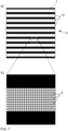
- Fig. 7 illustrates the realization of a structure 9 by means of a light modulator 7 with a plurality of pixels 8.
- Fig. 7a a structure 9 with a plurality of structural elements 10, in this case a striped grid.
- the structural elements 10 are therefore the individual grid lines.
- Fig. 7b shows an enlarged section of a single grating line.
- the grating line is made up of a large number of pixels 8 of the light modulator 7, i.e. the dimensions of the structural elements 10 are larger in both dimensions than the size of the pixels 8.
- the structures 9 realized by the light modulator 7 are shifted, i.e. the individual structural elements 10 are shifted here by integer multiples of the pixel size.
- the minimum shift of a structure in this binary light modulator 7 is predetermined by the pixel size and is therefore smaller than the dimensions of the structural elements 10.
- Subpixel shifts can be achieved, for example, by oblique patterns (aliasing effects), perforated patterns or multi-stage or analog modulators, if necessary in combination with additional Fourier filtering.
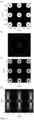
- Fig. 8 shows a first example of the generation of several independently positionable light distributions.
- Fig. 8a the structures realized with the first light modulator, in this case two stripe gratings with four grating lines each.
- Fig. 8b shows the corresponding interference pattern in the Fourier plane.
- the 0th order of the interference pattern is blocked by the second light modulator, which results in Fig. 8c ).
- the +1st order and the -1st order of the interference pattern interfere, which in the plane of the sample, ie the xy-plane, leads to the Fig. 8d ) interference patterns shown.
- the ⁇ 1st intensity minimum with the adjacent intensity maxima can be used, ie the 0th and the ⁇ 1st intensity maximum, which have approximately the same maximum intensity.
- Fig. 9 shows a second example for the generation of several independently positionable light distributions.
- Fig. 9a the structures realized with the first light modulator, in this case two stripe gratings with only two grating lines each. The lateral dimensions of the stripe gratings are smaller than in Fig. 8 example shown.
- Fig. 9b again shows the corresponding interference pattern in the Fourier plane. There, as before, the 0th order of the interference pattern is blocked by the second light modulator, which results in Fig. 9c ). In the further course, the +1st order and the -1st order of the interference pattern interfere, which in the plane of the sample leads to the Fig. 9d ) shown interference patterns.
- the ⁇ 1st intensity minimum with the adjacent 0th and ⁇ 1 intensity maxima can be used. Although these intensity maxima have different maximum intensities, the deviations do not affect the positioning accuracy.
- Fig. 10 shows an example of how to create a light distribution in the form of a bottle beam.
- Fig. 10a the structure realized with the first light modulator, in this case a ring structure.
- Fig. 10b shows the corresponding situation in the Fourier plane.
- the Fig. 10c shown image.
- the central intensity minimum is surrounded on all sides by an intensity maximum.
- the Fig. 10d shows the intensity curve shown as a section in the xz plane.
- the light distribution also exhibits an intensity minimum in the axial direction, adjacent to regions of increasing intensity. The light distribution thus allows position determination in three dimensions.
- the sample can be moved in the axial direction, for example.
- an additional dynamically focusing element can be arranged in the beam path, with which the light distribution can be shifted in the axial direction, e.g., a deformable mirror.
- Fig. 11 shows an example of the generation of several independently positionable light distributions in the form of bottle beams.
- Fig. 11a the structure realized with the first light modulator, in this case nine independently positionable ring structures.
- Fig. 11b shows the corresponding situation in the Fourier plane.
- the Fig. 11c shown image.
- the central intensity minimum is surrounded on all sides by an intensity maximum.
- the Fig. 11d shows the intensity curve shown as a section in the xz plane.
- all light distributions also exhibit an intensity minimum in the axial direction, adjacent to which areas of intensity increase are located, thus enabling position determination in three dimensions.
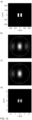
- Fig. 12 shows an example of the generation of a light distribution by temporally superimposing different partial light distributions.
- Fig. 12a the structure realized with the first light modulator, in this case a stripe grating with two grating lines.
- Fig. 12b shows the corresponding interference pattern in the Fourier plane.
- the +1st order of the interference pattern is blocked by the second light modulator, which results in Fig. 12c ).
- the 0th order and the -1st order of the interference pattern interfere, which in the plane of the sample, ie the xy-plane, leads to the Fig. 12d ) shown partial light distribution.
- the result is a light distribution with an intensity minimum and adjacent Intensity maxima.
- the -1st order of the interference pattern is subsequently blocked by the second light modulator in the Fourier plane, so that the 0th order and the +1st order of the interference pattern interfere in the further course.
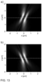
- the intensity distribution in the axial direction is interesting, which is Fig. 13 shown as a section in the xz-plane.
- Fig. 13a the intensity curve for the interference between 0th order -1st order of the interference pattern
- Fig. 13b the intensity curve for the interference between 0th order + 1st order of the interference pattern.
- the partial light distributions each have a tilted axis, which in Fig. 13a) and Fig. 13b ) is indicated by a dotted line. If the two partial light distributions are superimposed in time, ie they are radiated into the same position of the sample with a short time interval, the result is Fig. 14a ) is again shown as a section in the xz-plane. As can be clearly seen, the superimposed light distribution also has an intensity minimum in the axial direction, which is bordered by areas of intensity increase. As in Fig. 14b) and Fig. 14c ), this intensity minimum can be shifted in the axial direction by shifting the two partial light distributions relative to each other in the radial direction.
Landscapes
- Physics & Mathematics (AREA)
- Chemical & Material Sciences (AREA)
- General Physics & Mathematics (AREA)
- Analytical Chemistry (AREA)
- Health & Medical Sciences (AREA)
- Optics & Photonics (AREA)
- Immunology (AREA)
- Engineering & Computer Science (AREA)
- Multimedia (AREA)
- Nuclear Medicine, Radiotherapy & Molecular Imaging (AREA)
- Biochemistry (AREA)
- General Health & Medical Sciences (AREA)
- Pathology (AREA)
- Life Sciences & Earth Sciences (AREA)
- Computer Vision & Pattern Recognition (AREA)
- Chemical Kinetics & Catalysis (AREA)
- Investigating, Analyzing Materials By Fluorescence Or Luminescence (AREA)
- Microscoopes, Condenser (AREA)
Description
Die vorliegende Erfindung betrifft ein Verfahren, ein Computerprogramm mit Instruktionen sowie eine Vorrichtung zum parallelisierten Bestimmen von Positionen von Molekülen in einer Probe. Insbesondere betrifft die vorliegende Erfindung ein Verfahren, ein Computerprogramm mit Instruktionen sowie eine Vorrichtung zum parallelisierten Bestimmen von Positionen von zwei oder mehr gleichzeitig aktiven, voneinander beabstandeten Molekülen in einer oder mehreren Raumrichtungen in einer Probe mittels eines Lokalisationsmikroskops, wobei für das Bestimmen der Positionen der Moleküle Lichtverteilungen verwendet werden, die aufgrund von Interferenz kohärenten Lichts entstehen. Die vorliegende Erfindung betrifft zudem ein Lokalisationsmikroskop, das eine erfindungsgemäße Vorrichtung verwendet.The present invention relates to a method, a computer program with instructions, and a device for the parallel determination of positions of molecules in a sample. In particular, the present invention relates to a method, a computer program with instructions, and a device for the parallel determination of positions of two or more simultaneously active, spaced-apart molecules in one or more spatial directions in a sample using a localization microscope, wherein light distributions resulting from interference of coherent light are used to determine the positions of the molecules. The present invention also relates to a localization microscope that uses a device according to the invention.
Bei der MINFLUX-Mikroskopie handelt es sich um eine technische Umsetzung der Lokalisationsmikroskopie. Die Lokalisation von Fluorophoren in einer Probe erfolgt mittels strukturierter Anregungslichtverteilungen. Die Bezeichnung MINFLUX leitet sich ab aus dem zugrundeliegenden Konzept, die Koordinaten eines Moleküls mit einer minimalen Anzahl an Fluoreszenzphotonen zu bestimmen (englisch: MINimal emission FLUXes). Die grundlegende Besonderheit der MINFLUX-Mikroskopie ist, dass die Anregung der Fluorophore jeweils so erfolgt, dass ein zu lokalisierendes Fluorophor immer nah an einem oder in einem Minimum der Anregungslichtverteilung, welches idealerweise eine Nullstelle ist, platziert ist, wobei die Anregungslichtverteilung benachbart zum Minimum einen Intensitätsanstiegsbereich aufweisen muss. Hierdurch wird eine bessere Ausnutzung der Fluoreszenzphotonen hinsichtlich der Gewinnung von Information über die Lage des jeweiligen emittierenden Fluorophors erreicht. Dies gilt auch für Anwendungen, in denen die Bewegung von Fluorophoren über die Zeit verfolgt werden soll. Grundlagen der MINFLUX-Mikroskopie sind aus
In
Auf Basis dieser Grundlagen sind eine Reihe von Verfeinerungen zur Informationsgewinnung entstanden. Eine ausführliche Darstellung zur MINFLUX-Mikroskopie findet sich in "Nanometer resolution imaging and tracking of fluorescent molecules with minimal photon fluxes" von F. Balzarotti et al. [1]. Grundsätzlich muss, um ein Fluorophor mittels MINFLUX-Mikroskopie lokalisieren zu können, das Intensitätsminimum bzw. die Intensitätsnullstelle an einer Mehrzahl von Positionen relativ zur Lage des Fluorophors platziert werden. Hierfür muss in einem vorbereitenden Schritt eine Position des Fluorophors mit einer ersten, geringeren Genauigkeit abgeschätzt werden. Dies kann mittels gewöhnlicher Lokalisationsmikroskopie geschehen, wie z.B. PALM (Photoaktivierte Lokalisationsmikroskopie) oder STORM (Stochastische Optische Rekonstruktionsmikroskopie), oder mittels anderer bekannter Verfahren, wie z.B. solcher auf Basis der Anwendung strukturierter Beleuchtung. Anschließend wird eine Intensitätsverteilung von Anregungslicht an einer bekannten Position platziert, die derart gewählt ist, dass das Fluorophor nah am Minimum der Intensitätsverteilung liegt. Die Fluoreszenzantwort des Fluorophors wird gemessen. Dasselbe wird für eine oder mehrere weitere Positionen der Intensitätsverteilung wiederholt. Mittels einer Auswertung der Intensitätsverhältnisse ähnliche einem Triangulationsverfahren kann die Position des Fluorophors genauer bestimmt werden. Grundsätzlich steigt die Emissionsrate, je weiter das Fluorophor vom Anregungsminimum entfernt ist bzw. je weiter das Fluorophor in einen Intensitätsanstiegsbereich hinein verschoben ist. Diese genauer bestimmte Position kann nun als Ausgangsposition für eine Wiederholung der Abfolge der vorgenannten Schritte verwendet werden, wobei die Positionen dichter an die abgeschätzte Position des Fluorophors gelegt werden können. Insbesondere mit Blick auf die Verfolgung der Bewegung von Fluorophoren kann auch die Veränderung der Emissionsrate bei einer Verlagerung des Fluorophors in den Intensitätsanstiegsbereich hinein oder zum Minimum hin genutzt werden, um die Verlagerung des Fluorophors abzuschätzen.Based on these principles, a number of refinements for information acquisition have emerged. A detailed description of MINFLUX microscopy can be found in "Nanometer resolution imaging and tracking of fluorescent molecules with minimal photon fluxes" by F. Balzarotti et al. [1]. Fundamentally, in order to localize a fluorophore using MINFLUX microscopy, the intensity minimum or zero must be placed at a number of positions relative to the position of the fluorophore. For this purpose, a position of the fluorophore must be estimated with an initial, lower accuracy in a preparatory step. This can be done using conventional localization microscopy, such as PALM (Photoactivated Localization Microscopy) or STORM (Stochastic Optical Reconstruction Microscopy), or using other known methods, such as those based on the application of structured illumination. Subsequently, an intensity distribution of excitation light is placed at a known position, which is is chosen so that the fluorophore is close to the minimum of the intensity distribution. The fluorescence response of the fluorophore is measured. The same is repeated for one or more other positions in the intensity distribution. By evaluating the intensity ratios similar to a triangulation method, the position of the fluorophore can be determined more precisely. In principle, the emission rate increases the further the fluorophore is from the excitation minimum or the further the fluorophore is shifted into a region of intensity increase. This more precisely determined position can now be used as the starting position for repeating the sequence of the aforementioned steps, whereby the positions can be placed closer to the estimated position of the fluorophore. Particularly with a view to tracking the movement of fluorophores, the change in the emission rate when the fluorophore is shifted into the region of intensity increase or towards the minimum can also be used to estimate the displacement of the fluorophore.
Einige Aspekte der MINFLUX-Mikroskopie sind in
Mittels MINFLUX-Mikroskopie konnte die Position von Fluorophoren in zwei Raumrichtungen experimentell mit einer Unsicherheit von nur 1 nm bestimmt werden, d.h. die Genauigkeit der Lagebestimmung ist vergleichbar mit der Ausdehnung der Fluorophore selbst. Soll die Lage eines einzelnen Fluorophors mit einer gegebenen Messunsicherheit bestimmt werden, so wird hierfür eine geringere Zeit benötigt als bei einer Lagebestimmung mittels herkömmlicher Lokalisationsmikroskopie. Ein Nachteil der MINFLUX-Mikroskopie ist allerdings, dass bisher eine Lagebestimmung einer Vielzahl von Fluorophoren einen großen Zeitaufwand erfordert.Using MINFLUX microscopy, the position of fluorophores in two spatial directions could be determined experimentally with an uncertainty of only 1 nm, ie the accuracy of the position determination is comparable to the extent of the fluorophores themselves. If the position of a single fluorophore can be determined with a given measurement uncertainty, this requires less time than determining its position using conventional localization microscopy. However, a disadvantage of MINFLUX microscopy is that determining the position of a large number of fluorophores has been very time-consuming.
Bei allen Verfahren der Lokalisationsmikroskopie werden die Positionen einzelner Fluorophore hochgenau bestimmt. Aus der Menge vieler solcher Lokalisationen kann dann ein Bild der Probe aufgebaut werden, welches eine Auflösung aufweist, die sehr viel feiner ist als die durch das Abbe-Limit gegebene Grenzauflösung für Weitfeldabbildungen. Derart fein auflösende Mikroskopieverfahren werden als superauflösende Mikroskopieverfahren oder auch als Nanoskopieverfahren bezeichnet.In all localization microscopy techniques, the positions of individual fluorophores are determined with high precision. From the set of many such localizations, an image of the sample can then be constructed with a resolution much finer than the limiting resolution for wide-field imaging, determined by the Abbe limit. Such fine-resolution microscopy techniques are referred to as super-resolution microscopy or nanoscopy techniques.
Ein weiteres Mikroskopieverfahren, das eine Auflösung leicht unterhalb des klassischen Abbe-Limits ermöglicht bzw. konkret die Auflösung halb so großer Strukturen erlaubt wie nach dem Abbe-Limit, ist unter dem Begriff SIM bekannt (SIM: Structured Illumination Microscopy; Mikroskopie mit strukturierter Beleuchtung), z.B. aus dem Artikel "
Ein weiteres Konzept zur Erzielung von Superauflösung wird als ROSE bezeichnet (ROSE: Repetitive Optical Selective Exposure; Repetitive optische selektive Belichtung), ist z.B. aus dem Artikel "
Der Artikel "
Der Artikel "
Es ist eine Aufgabe der Erfindung, verbesserte Lösungen für das parallelisierte Bestimmen von Positionen von Molekülen in einer Probe bereitzustellen, durch die der Zeitaufwand für die Positionsbestimmung einer Vielzahl von Fluorophoren reduziert wird.It is an object of the invention to provide improved solutions for the parallelized determination of positions of molecules in a sample, which reduces the time required for the position determination of a large number of fluorophores.
Diese Aufgabe wird durch ein Verfahren mit den Merkmalen des Anspruchs 1, durch ein Computerprogramm mit Instruktionen mit den Merkmalen des Anspruchs 13, durch eine Vorrichtung mit den Merkmalen des Anspruchs 14 sowie durch ein Mikroskop mit den Merkmalen des Anspruchs 15 gelöst. Bevorzugte Ausgestaltungen der Erfindung sind Gegenstand der abhängigen Ansprüche.This object is achieved by a method having the features of
Gemäß einem ersten Aspekt der Erfindung umfasst ein Verfahren zum parallelisierten Bestimmen von Positionen von zwei oder mehr gleichzeitig aktiven, voneinander beabstandeten Molekülen in einer oder mehreren Raumrichtungen in einer Probe mittels eines Lokalisationsmikroskops, wobei für das Bestimmen der Positionen der Moleküle Lichtverteilungen verwendet werden, die aufgrund von Interferenz kohärenten Lichts entstehen, die Schritte:
- Erzeugen einer Mehrzahl von Lichtverteilungen unter Verwendung eines ersten Lichtmodulators mit einer Vielzahl von schaltbaren Pixeln, der in einer Bildebene des Lokalisationsmikroskops angeordnet ist, wobei jede Lichtverteilung ein lokales Intensitätsminimum und daran angrenzend Intensitätsanstiegsbereiche aufweist;
- Beleuchten jedes der zwei oder mehr Moleküle mit jeweils einer Lichtverteilung;
- für jede der Lichtverteilungen, Erfassen von durch die Moleküle emittierten Photonen für verschiedene Positionierungen der Lichtverteilung, wobei die Lichtverteilungen durch eine entsprechende Ansteuerung des ersten Lichtmodulators unabhängig voneinander positioniert werden; und
- Ableiten der Positionen der Moleküle auf Basis der für die verschiedenen Positionierungen der Lichtverteilungen erfassten Photonen.
- Generating a plurality of light distributions using a first light modulator having a plurality of switchable pixels arranged in an image plane of the localization microscope, wherein each light distribution has a local intensity minimum and adjacent intensity increase regions;
- Illuminate each of the two or more molecules with a light distribution;
- for each of the light distributions, detecting photons emitted by the molecules for different positionings of the light distribution, wherein the light distributions are positioned independently of each other by a corresponding control of the first light modulator; and
- Deriving the positions of the molecules based on the photons detected for the different positioning of the light distributions.
Gemäß einem weiteren Aspekt der Erfindung enthält ein Computerprogramm Instruktionen, die bei Ausführung durch einen Computer den Computer zur Ausführung der folgenden Schritte zum parallelisierten Bestimmen von Positionen von zwei oder mehr gleichzeitig aktiven, voneinander beabstandeten Molekülen in einer oder mehreren Raumrichtungen in einer Probe mittels eines Lokalisationsmikroskops veranlassen, wobei für das Bestimmen der Positionen der Moleküle Lichtverteilungen verwendet werden, die aufgrund von Interferenz kohärenten Lichts entstehen:
- Erzeugen einer Mehrzahl von Lichtverteilungen unter Verwendung eines ersten Lichtmodulators mit einer Vielzahl von schaltbaren Pixeln, der in einer Bildebene des Lokalisationsmikroskops angeordnet ist, wobei jede Lichtverteilung ein lokales Intensitätsminimum und daran angrenzend Intensitätsanstiegsbereiche aufweist;
- Beleuchten jedes der zwei oder mehr Moleküle mit jeweils einer Lichtverteilung;
- für jede der Lichtverteilungen, Erfassen von durch die Moleküle emittierten Photonen für verschiedene Positionierungen der Lichtverteilung, wobei die Lichtverteilungen durch eine entsprechende Ansteuerung des ersten Lichtmodulators unabhängig voneinander positioniert werden; und
- Ableiten der Positionen der Moleküle auf Basis der für die verschiedenen Positionierungen der Lichtverteilungen erfassten Photonen.
- Generating a plurality of light distributions using a first light modulator having a plurality of switchable pixels arranged in an image plane of the localization microscope, each light distribution having a local intensity minimum and adjacent intensity increase regions;
- Illuminate each of the two or more molecules with a light distribution;
- for each of the light distributions, detecting photons emitted by the molecules for different positionings of the light distribution, wherein the light distributions are positioned independently of each other by a corresponding control of the first light modulator; and
- Deriving the positions of the molecules based on the photons detected for the different positioning of the light distributions.
Der Begriff Computer ist dabei breit zu verstehen. Insbesondere umfasst er auch Mikrocontroller, eingebettete Systeme und andere prozessorbasierte Datenverarbeitungsvorrichtungen.The term "computer" should be understood broadly. In particular, it also includes microcontrollers, embedded systems, and other processor-based data processing devices.
Das Computerprogramm kann beispielsweise für einen elektronischen Abruf bereitgestellt werden oder auf einem computerlesbaren Speichermedium gespeichert sein.The computer program may, for example, be made available for electronic retrieval or stored on a computer-readable storage medium.
Gemäß einem weiteren Aspekt der Erfindung umfasst eine Vorrichtung zum parallelisierten Bestimmen von Positionen von zwei oder mehr gleichzeitig aktiven, voneinander beabstandeten Molekülen in einer oder mehreren Raumrichtungen in einer Probe mittels eines Lokalisationsmikroskops, wobei für das Bestimmen der Positionen der Moleküle Lichtverteilungen verwendet werden, die aufgrund von Interferenz kohärenten Lichts entstehen:
- eine Steuereinheit, die eingerichtet ist zum Ansteuern eines ersten Lichtmodulators mit einer Vielzahl von schaltbaren Pixeln, der in einer Bildebene des Lokalisationsmikroskops angeordnet ist, zum Erzeugen einer Mehrzahl von durch eine entsprechende Ansteuerung des ersten Lichtmodulators unabhängig voneinander positionierbaren Lichtverteilungen, wobei jede Lichtverteilung ein lokales Intensitätsminimum und daran angrenzend Intensitätsanstiegsbereiche aufweist; und
- eine Auswerteeinheit, die eingerichtet ist zum Ableiten der Positionen der Moleküle auf Basis von durch die Moleküle für jede der Lichtverteilungen emittierten Photonen für verschiedene Positionierungen der jeweiligen Lichtverteilungen.
- a control unit configured to control a first light modulator having a plurality of switchable pixels, which is arranged in an image plane of the localization microscope, to generate a plurality of light distributions that can be positioned independently of one another by correspondingly controlling the first light modulator, each light distribution having a local intensity minimum and adjacent intensity increase regions; and
- an evaluation unit configured to derive the positions of the molecules based on photons emitted by the molecules for each of the light distributions for different positionings of the respective light distributions.
Bei der erfindungsgemäßen Lösung wird eine Mehrzahl von Lichtverteilungen genutzt, um die Positionsbestimmung von Molekülen bzw. Fluorophoren mittels eines Lokalisationsmikroskops zu parallelisieren. Zu diesem Zweck werden die einzelnen Lichtverteilungen mittels eines Lichtmodulators erzeugt, der in einer Bildebene des Lokalisationsmikroskops angeordnet ist. Die Lichtverteilungen können durch eine entsprechende Ansteuerung des Lichtmodulators dabei unabhängig voneinander positioniert werden. Durch die parallelisierte Erfassung der Moleküle reduziert sich der Zeitaufwand für die Abtastung einer Probe erheblich. Die erfassten Moleküle bzw. Fluorophore müssen für die Erfassung gleichzeitig aktiv sein und einen Abstand haben, der eine gleichzeitige beugungslimitierte Detektion ermöglicht. Bei den Lichtverteilungen ist ein minimaler Abstand erforderlich. Weisen in Zeitabschnitten in Bereichen der Probe aktive Moleküle hierfür zu kleine Abstände auf, so werden diese in diesen Zeitabschnitten nicht beobachtet. Es werden bei der erfindungsgemäßen Lösung jeweils Moleküle bzw. Fluorophore beobachtet, die so weit voneinander entfernt sind, dass sich die Lichtverteilungen nicht berühren.The solution according to the invention uses a plurality of light distributions to parallelize the position determination of molecules or fluorophores using a localization microscope. For this purpose, the individual light distributions are generated using a light modulator arranged in an image plane of the localization microscope. The light distributions can be positioned independently of one another by appropriately controlling the light modulator. The parallel detection of the molecules significantly reduces the time required to scan a sample. The detected molecules or fluorophores must be active simultaneously for detection and have a distance that enables simultaneous diffraction-limited detection. A minimum distance is required for the light distributions. If active molecules in areas of the sample are too close together for this purpose during certain time periods, they will not be observed during these time periods. With the solution according to the invention, molecules or fluorophores are observed that are so far apart that the light distributions do not touch.
Die MINFLUX-Mikroskopie wird typischerweise mit Fluorophoren durchgeführt, die "blinken", d.h. zwischen fluoreszenzfähigen und nicht-fluoreszenzfähigen Zuständen wechseln. Dieser Wechsel zwischen den Zuständen kann dabei entweder bei fest eingestellten Umgebungsbedingungen rein zufällig erfolgen oder aber durch einen Schaltprozess, z.B. durch ein Deaktivierungslicht oder durch ein Aktivierungslicht oder durch eine Kombination eines Deaktivierungslichts zur Deaktivierung aller Moleküle und eines Aktivierungslichts, durch das wenige Moleküle aktiviert werden, induziert werden. So ist es möglich, dass jeweils in einem Lokalisationsbereich nur ein Fluorophor fluoreszenzfähig ist, insgesamt aber dennoch die gesamte Probe unter Nutzung der meisten Fluorophore abgebildet werden kann. Geeignete Fluorophore und Methoden zum Schalten schaltbarer Fluorophore sind dem Fachmann bekannt.MINFLUX microscopy is typically performed with fluorophores that "blink," i.e., switch between fluorescent and non-fluorescent states. This switch between states can occur either randomly under fixed environmental conditions or through a switching process, e.g., a deactivation light or an activation light, or a combination of a deactivation light to deactivate all molecules and an activation light. by which a few molecules are activated. This makes it possible for only one fluorophore to be fluorescent in a specific localization area, but the entire sample can still be imaged using most of the fluorophores. Suitable fluorophores and methods for switching switchable fluorophores are known to those skilled in the art.
Die Anordnung des Lichtmodulators in einer Bildebene hat den Vorteil, dass ein Verschieben der Lichtverteilungen in der Probe durch das direkte Abbilden von Strukturen bzw. Mustern auf dem Lichtmodulator in der Bildebene besonders einfach und somit schnell erreichbar ist: Das individuelle Verschieben der Lichtverteilungen entspricht dem individuellen Verschieben der Muster auf dem Lichtmodulator. Die jeweils erforderliche Verschiebung kann sehr schnell berechnet werden, woraus eine hohe Entscheidungsgeschwindigkeit resultiert.The arrangement of the light modulator in an image plane has the advantage that shifting the light distributions in the sample by directly imaging structures or patterns on the light modulator in the image plane is particularly easy and therefore quick to achieve: Individually shifting the light distributions corresponds to individually shifting the patterns on the light modulator. The required shift can be calculated very quickly, resulting in high decision speed.
Gemäß einem Aspekt der Erfindung ist ein zweiter Lichtmodulator zur Beeinflussung der Lichtverteilungen in einer Fourier-Ebene des Lokalisationsmikroskops angeordnet. Insbesondere ist der zweite Lichtmodulator eingerichtet, einzelne Beugungsordnungen zu blockieren. Durch den zweiten Lichtmodulator lassen sich die vom ersten Lichtmodulator erzeugten Lichtverteilungen gezielt weiter beeinflussen. Werden vom ersten Lichtmodulator beispielsweise mehrere Beugungsordnungen generiert, so können durch den zweiten Lichtmodulator diejenigen Beugungsordnungen ausgefiltert werden, die im weiteren Strahlengang nicht verwendet werden sollen. Die Filterung kann dabei situativ angepasst werden, sodass eine große Flexibilität erreicht wird.According to one aspect of the invention, a second light modulator is arranged in a Fourier plane of the localization microscope to influence the light distributions. In particular, the second light modulator is configured to block individual diffraction orders. The second light modulator can further influence the light distributions generated by the first light modulator in a targeted manner. If, for example, the first light modulator generates multiple diffraction orders, the second light modulator can filter out those diffraction orders that are not to be used in the further beam path. The filtering can be adapted to the situation, thus achieving great flexibility.
Gemäß einem Aspekt der Erfindung ist der erste Lichtmodulator ein Amplitudenmodulator oder ein Phasenmodulator. Vorzugsweise ist der erste Lichtmodulator ein zwischen zwei festen Zuständen schaltbarer Lichtmodulator. Binäre Lichtmodulatoren haben den Vorteil, dass sie sehr schnell sind, während analoge Phasenmodulatoren, wie sie typischerweise bei holographischen Herangehensweisen genutzt werden, deutlich langsamer sind. Der Lichtmodulator kann z.B. als Flüssigkristall-Modulator oder als mikro-elektromechanischer Modulator realisiert sein, insbesondere als Mikrospiegel-Array. Derartige Lichtmodulatoren sind kommerziell verfügbar, einfach zu realisieren und ermöglichen Bildraten von 30 kHz bis 50 kHz. Dabei ist zu erwarten, dass zukünftig noch höhere Bildraten erzielt werden. Beispielhaft kann ein Lichtmodulator mit 1920×1080 oder 2560×1600 schaltbaren Pixeln verwendet werden.According to one aspect of the invention, the first light modulator is an amplitude modulator or a phase modulator. Preferably, the first light modulator is a light modulator that can be switched between two fixed states. Binary light modulators have the advantage of being very fast, whereas analog phase modulators, as typically used in holographic approaches, are significantly slower. The light modulator can be implemented, for example, as a liquid crystal modulator or as a micro-electromechanical modulator, in particular as a micromirror array. Such light modulators are commercially available, easy to implement, and enable frame rates of 30 kHz to 50 kHz. It is expected that even higher frame rates will be achieved in the future. For example, a light modulator with 1920×1080 or 2560×1600 switchable pixels can be used.
Gemäß einem Aspekt der Erfindung werden zum Erzeugen der Lichtverteilungen mittels der schaltbaren Pixel des ersten Lichtmodulators eindimensionale oder zweidimensionale Strukturen ausgebildet. Vorzugsweise sind die eindimensionalen Strukturen Gitterstrukturen und die zweidimensionalen Strukturen Ringstrukturen. Durch jede eindimensionale Gitterstruktur wird in der Probe eine gitterähnliche Lichtverteilung aus aufeinanderfolgenden Intensitätsmaxima und Intensitätsminima erzielt, mit der die Position z.B. eines Fluorophors in einer Raumrichtung bestimmt werden kann. Für die Positionsbestimmung können insbesondere das zentrale Intensitätsmaximum und eines der beiden benachbarten Intensitätsmaxima oder die beiden hellsten Intensitätsmaxima mit dem zwischen den gewählten Maxima liegenden Intensitätsminimum genutzt werden. Für eine Positionsbestimmung in zwei Raumrichtungen muss zusätzlich eine Lichtverteilung anderer Orientierung bereitgestellt werden. Durch die Ringstrukturen kann eine Lichtverteilung in Form eines sogenannten "Bottle Beams" erzielt werden, d.h. einer Lichtverteilung, die eine in drei Raumrichtungen begrenzte Nullstelle aufweist und mit der eine Positionsbestimmung in drei Raumrichtungen möglich ist. Eine weitere Möglichkeit ist die Erzeugung von Lichtverteilungen in Form eines Donuts, d.h. Lichtverteilungen, die eine in zwei Raumrichtungen begrenzte Nullstelle aufweisen und mit denen eine Positionsbestimmung in zwei Raumrichtungen möglich ist. Zu diesem Zweck können Punkte bzw. Scheiben auf dem ersten Lichtmodulator dargestellt werden. Zusätzlich wird dann ein statischer oder dynamischer Phasenmodulator, wie aus der STED-Mikroskopie bekannt, genutzt, um eine Phasenrampe aufzuprägen.According to one aspect of the invention, one-dimensional or two-dimensional Structures are formed. Preferably, the one-dimensional structures are grating structures, and the two-dimensional structures are ring structures. Each one-dimensional grating structure creates a grating-like light distribution in the sample consisting of successive intensity maxima and intensity minima, which can be used to determine the position of, for example, a fluorophore in one spatial direction. For position determination, the central intensity maximum and one of the two adjacent intensity maxima, or the two brightest intensity maxima with the intensity minimum located between the selected maxima, can be used. For position determination in two spatial directions, a light distribution of a different orientation must also be provided. The ring structures can create a light distribution in the form of a so-called "bottle beam," i.e., a light distribution that has a zero point limited in three spatial directions and with which position determination in three spatial directions is possible. Another possibility is the generation of light distributions in the form of a donut, i.e., light distributions that have a zero point limited in two spatial directions and with which position determination in two spatial directions is possible. For this purpose, dots or discs can be displayed on the first light modulator. In addition, a static or dynamic phase modulator, as known from STED microscopy, is used to impose a phase ramp.
Gemäß einem Aspekt der Erfindung werden zum Positionieren der Lichtverteilungen die mittels der schaltbaren Pixel des ersten Lichtmodulators ausgebildeten Strukturen verschoben. Die Verschiebungen der Strukturen sind dabei vorzugsweise kleiner als Abmessungen von Strukturelementen der Strukturen, wobei die Abmessungen der Strukturelemente in beiden Dimensionen größer sind als eine Größe der Pixel. Beispielsweise kann eine mit den Pixeln ausgebildete Gitterlinie eine Linienbreite von zehn Pixeln haben. Ist das optische System so ausgestaltet, dass daraus eine Periode der Lichtverteilung in der Probe von 250 nm resultiert, so führt eine Verschiebung der Gitterlinien um einen Pixel zu einer Verschiebung der Lichtverteilung in der Probe von 25 nm.According to one aspect of the invention, the structures formed by the switchable pixels of the first light modulator are shifted to position the light distributions. The shifts of the structures are preferably smaller than the dimensions of structural elements of the structures, wherein the dimensions of the structural elements are larger in both dimensions than the size of the pixels. For example, a grating line formed with the pixels can have a line width of ten pixels. If the optical system is configured such that this results in a period of the light distribution in the sample of 250 nm, a shift of the grating lines by one pixel leads to a shift of the light distribution in the sample of 25 nm.
Gemäß einem Aspekt der Erfindung wird für aufeinanderfolgende Positionsbestimmungen mit einer Lichtverteilung ein Intensitätsverlauf der Lichtverteilung verändert, indem eine Struktureigenschaft der zugehörigen eindimensionalen oder zweidimensionalen Struktur verändert wird. Beispielsweise kann eine Flankensteilheit der an das lokale Intensitätsminimum angrenzenden Intensitätsanstiegsbereiche verändert werden, indem eine Gitterkonstante und/oder ein Aspektverhältnis der eindimensionalen Struktur oder ein Lochdurchmesser der zweidimensionalen Struktur verändert wird. Durch die Änderung der Lichtverteilung für aufeinanderfolgende Positionsbestimmungen bzw. Messungen kann sukzessive die Genauigkeit der Positionsbestimmung erhöht werden. Auf diese Weise kann die Position eines Moleküls oder Fluorophors in iterativen Schritten mit mehreren Zoomstufen zunehmend genauer bestimmt werden. Insbesondere bei Verwendung eines binären Lichtmodulators kann eine solche iterative Positionsbestimmung sehr schnell durchgeführt werden.According to one aspect of the invention, for successive position determinations with a light distribution, an intensity profile of the light distribution is changed by changing a structural property of the associated one-dimensional or two-dimensional structure. For example, a slope of the intensity increase regions adjacent to the local intensity minimum can be changed by changing a lattice constant and/or an aspect ratio of the one-dimensional structure or a hole diameter of the two-dimensional structure. By changing the By adjusting the light distribution for successive position determinations or measurements, the accuracy of the position determination can be successively increased. In this way, the position of a molecule or fluorophore can be determined with increasing precision in iterative steps with multiple zoom levels. Especially when using a binary light modulator, such iterative position determination can be performed very quickly.
Gemäß einem Aspekt der Erfindung resultieren die Lichtverteilungen aus einer zeitlichen Überlagerung verschiedener Teil-Lichtverteilungen. Dazu können beispielsweise in aufeinanderfolgenden Schritten verschiedene Beugungsordnungen eines vom ersten Lichtmodulators erzeugten Interferenzmusters zur Interferenz gebracht werden, wodurch jeweils eine Teil-Lichtverteilung entsteht, die gewissermaßen eine geneigte Achse aufweist. Die Richtung der Neigung hängt davon ab, welche Beugungsordnungen interferieren. Werden die resultierenden Teil-Lichtverteilungen zeitlich überlagert, so entsteht eine dreidimensionale akkumulierte Lichtverteilung, die in axialer Richtung ein Minimum an der Position des Schnittpunkts der geneigten Achsen aufweist, an das Intensitätsanstiegsbereiche angrenzen. Durch eine relative Verschiebung zwischen den beiden Teil-Lichtverteilungen in radialer Richtung, d.h. durch ein Verschieben der zugehörigen Strukturen auf dem ersten Lichtmodulator, kann der Schnittpunkt und damit die Position des Minimums in axialer Richtung verschoben werden. Dies ermöglicht eine außerordentlich schnelle Positionsbestimmung eines Moleküls oder Fluorophors in drei Dimensionen.According to one aspect of the invention, the light distributions result from a temporal superposition of different partial light distributions. For this purpose, for example, different diffraction orders of an interference pattern generated by the first light modulator can be caused to interfere in successive steps, resulting in a partial light distribution that has a tilted axis, so to speak. The direction of the tilt depends on which diffraction orders are interfering. If the resulting partial light distributions are temporally superimposed, a three-dimensional accumulated light distribution is created that has a minimum in the axial direction at the position of the intersection of the tilted axes, adjacent to which regions of intensity increase are located. By a relative shift between the two partial light distributions in the radial direction, i.e., by shifting the associated structures on the first light modulator, the intersection and thus the position of the minimum can be shifted in the axial direction. This enables extremely rapid position determination of a molecule or fluorophore in three dimensions.
Gemäß einem Aspekt der Erfindung wird mittels zumindest einer Lichtverteilung ein Marker in der Probe zum Ermitteln einer Drift erfasst. Alternativ kann aus gleichsinnigen Änderungen der gemessenen Positionen der Moleküle in aufeinanderfolgenden Messungen eine Drift ermittelt werden. Diese Ansätze sind besonders vorteilhaft, wenn nicht nur Positionen von Molekülen, sondern aus aufeinanderfolgenden Messungen die Bewegungen von Molekülen bestimmt werden sollen. Wird eine Bewegung eines fest positionierten Markers erfasst, können damit die gemessenen Bewegungen der Moleküle korrigiert werden. Zu diesem Zweck ist es allerdings erforderlich, einen geeigneten Marker in der Probe bereitzustellen. Bei der MINFLUX-Mikroskopie kann ein solcher Marker z.B. ein Fluorophor sein, da dieses aufgrund des MINFLUX-Prinzips kaum ausbleicht. Zum Bereitstellen eines Markers kann z.B. mit einem Bottle Beam aus einer gefärbten Struktur, z.B. Fasern in einer fixierten Zelle, die mit einem nicht-schaltbaren Fluorophor gefärbt sind, ein Bead herausgebleicht werden. Wird eine bestimmte Stelle für eine Weile beleuchtet, so wird die Faser rund um einen Punkt ausgebleicht. Auf diese Weise kann ein prinzipiell beliebig kleiner, dauerhaft leuchtender Fleck erzeugt werden. Dieser kann beispielsweise eine Größe von 40 nm bis 100 nm haben und dann anschließend schonend unter Nutzung des MINFLUX-Prinzips lokalisiert werden. Alternativ lässt sich aber auch aus einer gleichsinnigen Bewegungen einer Vielzahl von Molekülen ableiten, dass es zu einer relativen Verschiebung zwischen der Probe und dem Messaufbau gekommen ist. Die gemessenen Bewegungen der einzelnen Moleküle können dann um den gleichsinnigen Anteil der Bewegung korrigiert werden.According to one aspect of the invention, a marker in the sample is detected using at least one light distribution to determine drift. Alternatively, drift can be determined from consistent changes in the measured positions of the molecules in successive measurements. These approaches are particularly advantageous when not only the positions of molecules but also the movements of molecules are to be determined from successive measurements. If the movement of a fixedly positioned marker is detected, the measured movements of the molecules can be corrected. For this purpose, however, it is necessary to provide a suitable marker in the sample. In MINFLUX microscopy, such a marker can be a fluorophore, for example, since this hardly bleaches due to the MINFLUX principle. To provide a marker, a bottle beam can be used, for example, to bleach a bead from a colored structure, e.g., fibers in a fixed cell that are colored with a non-switchable fluorophore. If a specific location is illuminated for a while, the fiber is bleached around a point. In this way, a permanently luminous A spot can be generated. This spot can, for example, have a size of 40 nm to 100 nm and can then be gently localized using the MINFLUX principle. Alternatively, the co-directional movement of a large number of molecules can be used to determine that a relative displacement has occurred between the sample and the measurement setup. The measured movements of the individual molecules can then be corrected for the co-directional component of the movement.
Gemäß einem Aspekt der Erfindung weisen die Lichtverteilungen in der Probe laterale Abmessungen im Bereich von 0,5 µm bis 4 µm auf. Es hat sich gezeigt, dass bei diesen Abmessungen der Lichtverteilungen in der Probe zuverlässige Positionsbestimmungen erzielt werden und zugleich eine große Anzahl unabhängig voneinander positionierbarer Lichtverteilungen realisiert werden kann.According to one aspect of the invention, the light distributions in the sample have lateral dimensions in the range of 0.5 µm to 4 µm. It has been shown that these dimensions of the light distributions in the sample allow for reliable position determinations and, at the same time, a large number of independently positionable light distributions can be realized.
In einer Ausführungsform der Erfindung kann die Abschätzung der Positionen der aktiven Luminophore bzw. Fluorophore, die der Anwendung der Lokalisation nach dem MINFLUX-Prinzip vorausgeht, erfolgen, indem eine Sequenz von eindimensional gitterförmigen Beleuchtungslichtverteilungen, bevorzugt mittels des ersten Lichtmodulators, erzeugt wird, wobei sich jede Beleuchtungslichtverteilung der Sequenz über eine selbe Mehrzahl vereinzelter Fluorophore erstreckt. Die Positionen der mehreren Fluorophore können bevorzugt nach einem Verfahren, wie es aus dem Stand der Technik als SIMPLE, SIMFLUX oder ROSE bekannt ist, abgeschätzt werden. Anschließend erfolgt dann simultan für eine Mehrzahl der mehreren Fluorophore oder für alle Fluorophore die genauere Lokalisation jeweils nach dem MINFLUX-Prinzip.In one embodiment of the invention, the estimation of the positions of the active luminophores or fluorophores, which precedes the application of localization according to the MINFLUX principle, can be performed by generating a sequence of one-dimensional grid-shaped illumination light distributions, preferably using the first light modulator, wherein each illumination light distribution of the sequence extends over the same plurality of individual fluorophores. The positions of the multiple fluorophores can preferably be estimated using a method known from the prior art as SIMPLE, SIMFLUX, or ROSE. Subsequently, the more precise localization is performed simultaneously for a plurality of the multiple fluorophores or for all fluorophores, each according to the MINFLUX principle.
In einer Ausführungsform der Erfindung können zunächst mit einer Lichtverteilung einer geeigneten Wellenlänge unter Verwendung geeigneter projizierter Muster Fluorophore gezielt nur in bestimmten Bereichen in einen fluoreszenzfähigen Zustand versetzt werden oder gezielt in Teilbereichen in einem fluoreszenzfähigen Zustand belassen werden. Hierfür können neben den oben beschriebenen Mikrogittern und Donuts auch andere Grundmuster verwendet werden. Insbesondere kann die Lichtverteilung insgesamt oder abschnittsweise ein Punktgitter sein. Außerdem sind kontinuierliche flächige Beleuchtungsmuster mit kontinuierlich variierender akkumulierter Lichtstärke möglich, z.B. indem ein DMD im Graustufen-Betrieb benutzt wird, die an die Dichteverteilung der beobachteten Struktur angepasst sind, sodass eine gewünschte Dichteverteilung an aktivierten Molekülen gezielt erzeugt werden kann. Dabei kann bei Verwendung entsprechender Fluorophore beispielsweise für die Aktivierung bevorzugt derselbe Lichtmodulator in einer Bildebene verwendet werden wie für die folgende Anregung.In one embodiment of the invention, fluorophores can first be specifically rendered fluorescent in specific areas using a light distribution of a suitable wavelength and suitable projected patterns, or can be specifically left fluorescent in specific areas. In addition to the microgratings and donuts described above, other basic patterns can be used for this purpose. In particular, the light distribution can be a point grating overall or in sections. Furthermore, continuous planar illumination patterns with continuously varying accumulated light intensity are possible, e.g., by using a DMD in grayscale mode, which are adapted to the density distribution of the observed structure, so that a desired density distribution of activated molecules can be specifically generated. When using appropriate fluorophores, for example, the same light modulator in an image plane can preferably be used for activation as for the subsequent excitation.
Es kann auch eine Abfolge oder eine Kombination verschiedener Lichtverteilungen verwendet werden, beispielsweise eine Abfolge eines Musters von Aktivierungslicht mit einer so angepassten Intensitätsverteilung, dass inaktive Fluorophore in Bereichen der Intensitätsmaxima mit einer geeigneten Wahrscheinlichkeit in einen aktiven Zustand geschaltet werden, und eines korrespondierenden Musters von Deaktivierungslicht, welches in Bereichen der Intensitätsmaxima des Aktivierungslichts Nullstellen aufweist und somit dort Fluorophore in aktivem Zustand belässt. Die Einstellung von Aktivierungslicht derart, dass nur eine geeignete, geringe Menge der Fluorophore aktiviert wird, ist dem Fachmann grundsätzlich bekannt. Anschließend kann dann in den so vorbereiteten Bereichen parallel das MINFLUX-Prinzip genutzt werden.A sequence or combination of different light distributions can also be used, for example, a sequence of a pattern of activation light with an intensity distribution adjusted so that inactive fluorophores are switched to an active state with a suitable probability in areas of intensity maxima, and a corresponding pattern of deactivation light, which has zero points in areas of the intensity maxima of the activation light, thus leaving fluorophores in the active state there. Adjusting the activation light such that only a suitable, small amount of fluorophores is activated is generally known to those skilled in the art. The MINFLUX principle can then be used in parallel in the areas prepared in this way.
Es wird also dafür gesorgt, dass von Vornherein recht genau bekannt ist, wo überhaupt Fluorophore in fluoreszenzfähigem Zustand sein können bzw. in welchen Bereichen die Dichte fluoreszenzfähiger Fluorophore für eine Einzelfluorophordetektion geeignet ist, und nutzt dann aus, dass die Teilgitter unabhängig verschoben werden können.This ensures that it is known quite precisely from the outset where fluorophores can be in a fluorescent state or in which areas the density of fluorescent fluorophores is suitable for single fluorophore detection, and then exploits the fact that the sub-gratings can be shifted independently.
Es kann für jedes der zu lokalisierenden Fluorophore auch eine Kombination einer Anregungslichtverteilung und einer Deaktivierungslichtverteilung vorteilhaft verwendet werden, bei der das Deaktivierungslicht STED-Licht ist. Hierbei decken sich vorteilhaft jeweils mindestens ein lokales zentrales Minimum der STED-Lichtverteilung und das Minimum der Anregungslichtverteilung, welches für die Lokalisation genutzt wird, d.h. innerhalb dessen sich das jeweils zu lokalisierende Fluorophor gemäß der vorgelagerten Ortsabschätzung jeweils befindet. Hierbei müssen sich die Lichtverteilungen nicht vollständig entsprechen. Beispielsweise kann als STED-Lichtverteilung jeweils ein Donut gewählt werden und als Anregungslichtverteilung ein eindimensionales Gitter. Zur Lokalisierung der Fluorophore können dann die Anregungslichtverteilungen und die STED-Lichtverteilungen gleichzeitig umpositioniert, d.h. verschoben und ggf. umorientiert werden, oder es können Anregungslichtverteilungen umpositioniert werden, während die STED-Lichtverteilungen ortsfest belassen werden, sodass Anregungsminima jeweils mehrfach unterschiedlich jeweils innerhalb eines Bereichs eines STED-Minimums positioniert werden, oder es können die Anregungslichtverteilungen ortsfest belassen und die STED-Lichtverteilungen umpositioniert werden. Denkbar sind auch Kombinationen der drei genannten Varianten. Alternativ oder zusätzlich zu der Umpositionierung können auch die Abmessungen und/oder Intensitäten der Lichtverteilungen des Anregungs- und /oder des STED-Lichts geändert werden. Beispielsweise können zu Beginn STED-Donuts mit räumlich weiter ausgedehntem Minimum mit Anregungslichtverteilungen überlagert werden und in folgenden Schritten können diese STED-Donuts z.B. in Abhängigkeit von der bereits erzielten Lokalisationsgenauigkeit verengt werden und/oder ihre Intensität kann erhöht werden. In allen hier genannten Fällen wird für die Erzeugung der Lichtverteilungen der zwei Lichtarten bevorzugt je Lichtart ein Lichtmodulator, der jeweils in einer Bildebene innerhalb eines zugehörigen Anregungs- bzw. STED-Lichtpfades angeordnet ist, verwendet. Die Lichtpfade können in Richtung der Lichtwege gesehen z.B. mittels eines Strahlvereinigers, der ein dichroitisches Bauteil sein kann, vereinigt werden.For each of the fluorophores to be localized, a combination of an excitation light distribution and a deactivation light distribution can also be advantageously used, where the deactivation light is STED light. In this case, at least one local central minimum of the STED light distribution and the minimum of the excitation light distribution used for localization, i.e., within which the fluorophore to be localized is located according to the upstream location estimation, advantageously coincide. The light distributions do not have to correspond completely. For example, a donut can be selected as the STED light distribution and a one-dimensional grating as the excitation light distribution. To localize the fluorophores, the excitation light distributions and the STED light distributions can be repositioned simultaneously, i.e. shifted and possibly reoriented, or the excitation light distributions can be repositioned while the STED light distributions remain stationary, so that excitation minima are positioned several times differently within a range of a STED minimum, or the excitation light distributions can be left stationary and the STED light distributions repositioned. Combinations of the three variants mentioned are also conceivable. Alternatively, or in addition to the repositioning, the dimensions and/or intensities of the light distributions of the excitation and/or STED light can also be changed. For example, STED donuts with a spatially more extended minimum can be overlaid with excitation light distributions at the beginning, and in the following steps, these STED donuts, for example, can be narrowed depending on the localization accuracy already achieved and/or their intensity can be increased. In all cases mentioned here, a light modulator is preferably used for each light type to generate the light distributions of the two light types. Each light type is arranged in an image plane within a corresponding excitation or STED light path. The light paths can be combined, viewed in the direction of the light paths, for example, using a beam combiner, which can be a dichroic component.
In einer weiteren Variante, bei der eine Kombination einer Anregungslichtverteilung und einer Deaktivierungslichtverteilung verwendet wird, bei der das Deaktivierungslicht STED-Licht ist, weisen die STED-Lichtverteilungen lokale Minima auf, nicht aber die Anregungslichtverteilungen. In dieser Variante wird nicht das MINFLUX-Prinzip umgesetzt, die Positionen der zu lokalisierenden Moleküle werden aber dennoch auf Basis der für die verschiedenen Positionierungen der Lichtverteilungen erfassten Photonen bestimmt, bevorzugt mittels eines ratiometrischen Verfahrens. Beispielsweise können Luminophore oder Fluorophore, die in einen Schutzzustand versetzt werden können, verwendet werden. Solche Luminophore und deren Verwendung in einem besonderen STED-Verfahren sind beispielsweise aus
In entsprechender Weise können auch Fluorophore verwendet werden, die sich im Ausgangszustand in einem Schutzzustand befinden. Diese können dann lokal mittels Aktivierungslichtverteilungen, die bevorzugt ein beugungsbegrenztes zentrales Maximum aufweisen, aktiviert werden und folgend, wie beschrieben, mittels einer Kombination aus Anregungs- und STED-Licht lokalisiert werden. Alternativ kann ihre Lokalisation auch ausschließlich unter Verwendung von Anregungslichtverteilungen erfolgen.Similarly, fluorophores that are initially in a protected state can also be used. These can then be locally activated using activation light distributions, which preferably exhibit a diffraction-limited central maximum, and subsequently localized, as described, using a combination of excitation and STED light. Alternatively, their localization can also be achieved using excitation light distributions alone.
Gemäß einem Aspekt der Erfindung werden die durch die Moleküle emittierten Photonen mit einer Kamera oder einem Array von Photonenzählern erfasst. Die Verwendung einer Kamera hat dabei den Vorteil, dass eine Kamera preisgünstig ist und eine schnelle Auslesung ermöglicht. Die Verwendung von Photonenzählern hat den Vorteil, dass diese sehr effizient bei der Detektion von Photonen sind und zudem eine sehr hohe Zeitauflösung aufweisen. Bei den Photonenzählern kann es sich beispielsweise um Einzelphoton-Avalanche-Dioden (SPAD: Single-Photon Avalanche Diode) handeln.According to one aspect of the invention, the photons emitted by the molecules are detected with a camera or an array of photon counters. The use of a camera has the advantage of being inexpensive and enabling fast readout. The use of photon counters has the advantage of being very efficient in detecting photons and also having a very high temporal resolution. The photon counters can be, for example, single-photon avalanche diodes (SPADs).
Gemäß einem weiteren Aspekt der Erfindung umfasst ein erfindungsgemäßes Mikroskop:
- eine Lichtquelle zum Erzeugen von kohärentem Licht;
- einen ersten Lichtmodulator mit einer Vielzahl von schaltbaren Pixeln, der in einer Bildebene des Mikroskops angeordnet ist, zum Erzeugen einer Mehrzahl von Lichtverteilungen, die aufgrund von Interferenz kohärenten Lichts entstehen, wobei jede Lichtverteilung ein lokales Intensitätsminimum und daran angrenzend Intensitätsanstiegsbereiche aufweist;
- optische Mittel zum Beleuchten von zwei oder mehr voneinander beabstandeten Molekülen in einer Probe mit jeweils einer Lichtverteilung;
- eine Detektoreinheit zum Erfassen von durch die Moleküle für jede der Lichtverteilungen emittierten Photonen für verschiedene Positionierungen der Lichtverteilungen, wobei die Lichtverteilungen durch eine entsprechende Ansteuerung des ersten Lichtmodulators unabhängig voneinander positionierbar sind; und
- eine erfindungsgemäße Vorrichtung zum Bestimmen von Positionen der zwei oder mehr Moleküle in einer oder mehreren Raumrichtungen.
- a light source for generating coherent light;
- a first light modulator having a plurality of switchable pixels arranged in an image plane of the microscope for generating a plurality of light distributions resulting from interference of coherent light, each light distribution having a local intensity minimum and adjacent intensity increase regions;
- optical means for illuminating two or more spaced-apart molecules in a sample, each with a light distribution;
- a detector unit for detecting photons emitted by the molecules for each of the light distributions for different positioning of the light distributions, wherein the light distributions can be positioned independently of one another by appropriately controlling the first light modulator; and
- a device according to the invention for determining positions of two or more molecules in one or more spatial directions.
Weitere Merkmale der vorliegenden Erfindung werden aus der nachfolgenden Beschreibung und den angehängten Ansprüchen in Verbindung mit den Figuren ersichtlich.
- Fig. 1
- zeigt schematisch ein Verfahren zum parallelisierten Bestimmen von Positionen von zwei oder mehr gleichzeitig aktiven, voneinander beabstandeten Molekülen in einer oder mehreren Raumrichtungen in einer Probe;
- Fig. 2
- zeigt eine erste Ausführungsform einer Vorrichtung zum parallelisierten Bestimmen von Positionen von zwei oder mehr gleichzeitig aktiven, voneinander beabstandeten Molekülen in einer oder mehreren Raumrichtungen in einer Probe;
- Fig. 3
- zeigt eine zweite Ausführungsform einer Vorrichtung zum parallelisierten Bestimmen von Positionen von zwei oder mehr gleichzeitig aktiven, voneinander beabstandeten Molekülen in einer oder mehreren Raumrichtungen in einer Probe;
- Fig. 4
- zeigt eine Probe mit einer Vielzahl von Molekülen;
- Fig. 5
- zeigt einen Intensitätsverlauf über einen Querschnitt durch eine Lichtverteilung;
- Fig. 6
- zeigt einen prinzipiellen Aufbau eines Mikroskops, in dem eine erfindungsgemäße Lösung realisiert ist;
- Fig. 7
- veranschaulicht die Realisierung einer Struktur mittels eines Lichtmodulators mit einer Vielzahl von Pixeln;
- Fig. 8
- zeigt ein erstes Beispiel für die Erzeugung mehrerer unabhängig voneinander positionierbarer Lichtverteilungen;
- Fig. 9
- zeigt ein zweites Beispiel für die Erzeugung mehrerer unabhängig voneinander positionierbarer Lichtverteilungen;
- Fig. 10
- zeigt ein Beispiel für die Erzeugung einer Lichtverteilung in Form eines Bottle Beams, der eine in drei Raumrichtungen begrenzte Nullstelle aufweist;
- Fig. 11
- zeigt ein Beispiel für die Erzeugung mehrerer unabhängig voneinander positionierbarer Lichtverteilungen in Form von Bottle Beams;
- Fig. 12
- zeigt ein Beispiel für die Erzeugung einer Lichtverteilung durch eine zeitliche Überlagerung verschiedener Teil-Lichtverteilungen;
- Fig. 13
- zeigt axiale Schnitte durch die für die Überlagerung verwendeten Interferenzmuster; und
- Fig. 14
- zeigt axiale Schnitte durch die entsprechend
Fig. 12 erzeugte Lichtverteilung für verschiedene relative laterale Verschiebungen der Teil-Lichtverteilungen.
- Fig. 1
- shows schematically a method for the parallel determination of positions of two or more simultaneously active, spaced-apart molecules in one or more spatial directions in a sample;
- Fig. 2
- shows a first embodiment of a device for the parallel determination of positions of two or more simultaneously active, spaced-apart molecules in one or more spatial directions in a sample;
- Fig. 3
- shows a second embodiment of a device for the parallel determination of positions of two or more simultaneously active, spaced-apart molecules in one or more spatial directions in a sample;
- Fig. 4
- shows a sample with a variety of molecules;
- Fig. 5
- shows an intensity curve over a cross section through a light distribution;
- Fig. 6
- shows a basic structure of a microscope in which a solution according to the invention is implemented;
- Fig. 7
- illustrates the realization of a structure using a light modulator with a large number of pixels;
- Fig. 8
- shows a first example of the generation of several independently positionable light distributions;
- Fig. 9
- shows a second example of the generation of several independently positionable light distributions;
- Fig. 10
- shows an example of the generation of a light distribution in the form of a bottle beam, which has a zero point limited in three spatial directions;
- Fig. 11
- shows an example of the generation of several independently positionable light distributions in the form of bottle beams;
- Fig. 12
- shows an example of the generation of a light distribution by temporal superposition of different partial light distributions;
- Fig. 13
- shows axial sections through the interference patterns used for the superposition; and
- Fig. 14
- shows axial sections through the corresponding
Fig. 12 generated light distribution for different relative lateral shifts of the partial light distributions.
Zum besseren Verständnis der Prinzipien der vorliegenden Erfindung werden nachfolgend Ausführungsformen der Erfindung anhand der Figuren detaillierter erläutert. Es versteht sich, dass sich die Erfindung nicht auf diese Ausführungsformen beschränkt und dass die beschriebenen Merkmale auch kombiniert oder modifiziert werden können, ohne den Schutzbereich der Erfindung zu verlassen, wie er in den angehängten Ansprüchen definiert ist.To better understand the principles of the present invention, embodiments of the invention are explained in more detail below with reference to the figures. It is understood that the invention is not limited to these embodiments and that the described features may also be combined or modified without departing from the scope of the invention as defined in the appended claims.
Die Steuereinheit 22 und die Auswerteeinheit 23 können von einer Kontrolleinheit 24 gesteuert werden. Über eine Benutzerschnittstelle 26 können gegebenenfalls Einstellungen der Steuereinheit 22, der Auswerteeinheit 23 oder der Kontrolleinheit 24 geändert werden. Die in der Vorrichtung 20 anfallenden Daten können bei Bedarf in einem Speicher 25 der Vorrichtung 20 abgelegt werden, beispielsweise für eine spätere Auswertung oder für eine Nutzung durch die Komponenten der Vorrichtung 20. Die Steuereinheit 22, die Auswerteeinheit 23 sowie die Kontrolleinheit 24 können als dedizierte Hardware realisiert sein, beispielsweise als integrierte Schaltungen. Natürlich können sie aber auch teilweise oder vollständig kombiniert oder als Software implementiert werden, die auf einem geeigneten Prozessor läuft, beispielsweise auf einer GPU oder einer CPU. Die Schnittstelle 21 kann auch in Form getrennter Ein- und Ausgänge implementiert sein.The
Der Prozessor 32 kann eine oder mehrere Prozessoreinheiten umfassen, beispielsweise Mikroprozessoren, digitale Signalprozessoren oder Kombinationen daraus.The
Die Speicher 25, 31 der beschriebenen Ausführungsformen können sowohl volatile als auch nichtvolatile Speicherbereiche aufweisen und unterschiedlichste Speichergeräte und Speichermedien umfassen, beispielsweise Festplatten, optische Speichermedien oder Halbleiterspeicher.The
Der erste Lichtmodulator 7, der zweite Lichtmodulator 12 und die Lichtquelle 15 werden von einer erfindungsgemäßen Vorrichtung 20 zum Bestimmen der Positionen der Moleküle angesteuert, die zudem die Daten der Detektoreinheit 16 auswertet. Der Einfachheit halber sind weitere Komponenten des Lokalisationsmikroskops 40, z.B. für die Beeinflussung der Polarisation oder eine Bewegung der Linsen 14 oder der Probe 1, in
Ideal ist der in
In der Praxis ist es am einfachsten realisierbar, den zweiten Lichtmodulator 12, der als Raumfilter dient, in eine Fokalebene der Linse 14 nach dem ersten Lichtmodulator 7 zu stellen und außerdem den ersten Lichtmodulator 7 in eine Bildebene zur Objektebene zu stellen. Abweichungen vom Idealzustand an anderen Stellen können im Grunde leichter toleriert werden, aber es ist natürlich sehr einfach, den Aufbau von 7 über die erste Linse 14 bis zum Raumfilter 12 ideal aufzubauen.In practice, the simplest way to achieve this is to place the second
Typischerweise sind STED-Mikroskope aufgebaut aus einem Mikroskopstativ mit einem eingebauten Objektiv und einer zugehörigen Tubus-Linse. Dabei ist bekannt, an welcher Stelle die (virtuelle) hintere Fokalebene liegt. Häufig wird diese in der Praxis als Pupillenebene oder einfach Pupille bezeichnet. Diese Ebene ist die Ebene, auf die die weitere Optik bezogen werden muss, d.h. wenn in der Objektebene kollimiert beleuchtet werden soll, dann muss der einfallende Strahl in diese Ebene, die dann am Ende innerhalb der geometrischen Abmessungen des Objektivs liegt oder jedenfalls liegen kann, fokussiert werden, d.h. er muss so eingerichtet werden, dass er in Abwesenheit des Objektivs an dieser Stelle einen Fokus bilden würde. Gleichzeitig ist diese Ebene die Ebene, in der die Feldverteilung vorliegen soll, deren Fouriertransfomierte im Objekt vorliegen soll. In der Praxis kann man, wenn das Objektiv ausgebaut ist, in diese Ebene eine Punktquelle stellen und diese durch die Tubus-Linse abbilden. Man erhält dann genau dort, wohin die Punktquelle abgebildet wird, eine zur Fourier-Ebene konjugierte Ebene, was gerade wieder eine Fourier-Ebene ist. Es ist dann leicht, weitere Fourier-Ebenen 13 bzw. Bildebenen 11 zu bestimmen.Typically, STED microscopes consist of a microscope stand with a built-in objective and an associated tube lens. The location of the (virtual) rear focal plane is known. In practice, this is often referred to as the pupil plane or simply the pupil. This plane is the plane to which the further optics must be referenced. This means that if collimated illumination is to be achieved in the object plane, the incident beam must be focused into this plane, which ultimately lies, or at least can lie, within the geometric dimensions of the objective. This means that it must be aligned so that, in the absence of the objective, it would form a focus at this point. At the same time, this plane is the plane in which the field distribution should exist, the Fourier transform of which should be present in the object. In practice, once the objective is removed, a point source can be placed in this plane and imaged through the tube lens. One then obtains a plane conjugate to the Fourier plane exactly where the point source is imaged, which is itself a Fourier plane. It is then easy to determine further Fourier planes 13 or image planes 11.
-
[1]
F. Balzarotti et al.: "Nanometer resolution imaging and tracking of fluorescent molecules with minimal photon fluxes", Science, Vol. 355 (2017), S. 606-612 F. Balzarotti et al.: "Nanometer resolution imaging and tracking of fluorescent molecules with minimal photon fluxes", Science, Vol. 355 (2017), pp. 606-612 -
[2]
M. G. L. Gustafsson: "Surpassing the lateral resolution limit by a factor of two using structured illumination microscopy", Journal of Microscopy, Vol. 198 (2000), S. 82-87 MGL Gustafsson: "Surpassing the lateral resolution limit by a factor of two using structured illumination microscopy", Journal of Microscopy, Vol. 198 (2000), pp. 82-87 -
[3]
M. G. L. Gustafsson: "Nonlinear structured-illumination microscopy: Wide-field fluorescence imaging with theoretically unlimited resolution", Proceedings of the National Academy of Sciences, Vol. 102 (2005), S. 13081-13086 MGL Gustafsson: "Nonlinear structured-illumination microscopy: Wide-field fluorescence imaging with theoretically unlimited resolution", Proceedings of the National Academy of Sciences, Vol. 102 (2005), pp. 13081-13086 -
[4]
L. Gu et al.: "Molecular resolution imaging by repetitive optical selective exposure", Nature Methods, Vol. 16 (2019), S. 1114-1118 L. Gu et al.: "Molecular resolution imaging by repetitive optical selective exposure", Nature Methods, Vol. 16 (2019), pp. 1114-1118 -
[5]
L. Reymond et al.: "SIMPLE: Structured illumination based point localization estimator with enhanced precision", Optics Express, Vol. 27 (2019), S. 24578-24590 L. Reymond et al.: "SIMPLE: Structured illumination based point localization estimator with enhanced precision", Optics Express, Vol. 27 (2019), pp. 24578-24590 -
[6]
J. Cnossen et al.: "Localization microscopy at doubled precision with patterned illumination", Nature Methods, Vol. 17 (2020), S. 59-63 J. Cnossen et al.: "Localization microscopy at doubled precision with patterned illumination", Nature Methods, Vol. 17 (2020), pp. 59-63
- 11
- Probesample
- 22
- Molekülmolecule
- 33
- Kohärentes LichtCoherent light
- 44
- LichtverteilungLight distribution
- 55
- IntensitätsminimumIntensity minimum
- 66
- IntensitätsanstiegsbereichIntensity increase range
- 77
- Erster LichtmodulatorFirst light modulator
- 88
- Pixelpixel
- 99
- Strukturstructure
- 1010
- StrukturelementStructural element
- 1111
- BildebeneImage plane
- 1212
- Zweiter LichtmodulatorSecond light modulator
- 1313
- Fourier-EbeneFourier plane
- 1414
- Linselens
- 1515
- Lichtquellelight source
- 1616
- DetektoreinheitDetector unit
- 1717
- Strahlteilerbeam splitter
- 2020
- Vorrichtungdevice
- 2121
- Schnittstelleinterface
- 2222
- SteuereinheitControl unit
- 2323
- AuswerteeinheitEvaluation unit
- 2424
- KontrolleinheitControl unit
- 2525
- Speichermemory
- 2626
- BenutzerschnittstelleUser interface
- 3030
- Vorrichtungdevice
- 3131
- Speichermemory
- 3232
- Prozessorprocessor
- 3333
- EingangEntrance
- 3434
- AusgangExit
- 4040
- Mikroskopmicroscope
- Pipi
- Positionposition
- S1S1
- Erzeugen einer Mehrzahl von LichtverteilungenGenerating a variety of light distributions
- S2S2
- Beleuchten von Molekülen mit jeweils einer LichtverteilungIlluminating molecules with one light distribution each
- S3S3
- Positionieren der Lichtverteilungen unabhängig voneinanderPositioning of the light distributions independently of each other
- S4S4
- Erfassen von emittierten Photonen für verschiedene Positionierungen der LichtverteilungenDetection of emitted photons for different positioning of the light distributions
- S5S5
- Ableiten der Positionen der Moleküle auf Basis der emittierten PhotonenDeriving the positions of the molecules based on the emitted photons
Claims (15)
- A method for parallelized determination of positions (Pi) of two or more simultaneously active, spaced-apart molecules (2) in one or more spatial directions in a sample (1) using a localization microscope (40), wherein light distributions (4) arising due to interference of coherent light are used for determining the positions (Pi) of the molecules (2), comprising the steps of:- generating (S1) a plurality of light distributions (4) using a first light modulator (7) having a plurality of switchable pixels (8) disposed in an image plane (11) of the localization microscope (40), each light distribution (4) having a local intensity minimum (5) and regions (6) with an intensity increase adjacent thereto;- illuminating (S2) each of the two or more molecules (2) with one light distribution (4) each;- for each of the light distributions (4), detecting (S4) photons emitted by the molecules (2) for different positionings of the light distribution (4), the light distributions (4) being positioned (S3) independently of each other by controlling the light modulator (7) accordingly; and- deriving (S5) the positions (Pi) of the molecules (2) based on the photons detected for the different positionings of the light distributions (4).
- The method according to claim 1, wherein a second light modulator (12) for influencing the light distributions (4) is arranged in a Fourier plane (13) of the localization microscope (40).
- The method according to claim 2, wherein the second light modulator (12) is arranged to block individual diffraction orders.
- The method according to any one of the preceding claims, wherein the first light modulator (7) is an amplitude modulator or a phase modulator, preferably an amplitude modulator or a phase modulator that is switchable between two fixed states.
- The method according to any one of the preceding claims, wherein one-dimensional structures (9), preferably grating structures, or two-dimensional structures (9), preferably ring structures, are formed by means of the switchable pixels (8) of the first light modulator (7) for generating (S1) the light distributions (4).
- The method according to claim 5, wherein the structures (9) formed by means of the switchable pixels (8) of the first light modulator (7) are shifted for positioning (S3) the light distributions (4).
- The method according to claim 6, wherein displacements of the structures (9) are preferably smaller than dimensions of structural elements (10) of the structures (9), wherein the dimensions of the structural elements (10) of the structures (9) are in both dimensions larger than a size of the pixels (8).
- The method according to any one of claims 5 to 7, wherein for successive position determinations with a light distribution (4), an intensity profile of the light distribution (4) is changed by changing a structural property of the associated one-dimensional or two-dimensional structure (9), wherein preferably an edge steepness of the regions (6) with an intensity increase adjacent to the local intensity minimum (5) is changed by changing a grating constant and/or an aspect ratio of the one-dimensional structure or a hole diameter of the two-dimensional structure.
- The method according to any one of the preceding claims, wherein the light distributions (4) result from a temporal superposition of different partial light distributions, which in turn preferably result from the interference of different diffraction orders of an interference pattern generated by the first light modulator (7).
- The method according to any one of the preceding claims, wherein a marker (6) in the sample (1) is detected using at least one light distribution (4) for determining a drift, and/or wherein a drift is determined from changes in the same direction in the measured positions (Pi) of molecules (2) in successive measurements.
- The method according to any one of the preceding claims, wherein the light distributions (4) in the sample (1) have lateral dimensions in the range of 0.5 µm to 4 µm.
- The method according to any one of the preceding claims, wherein the photons emitted by the molecules (2) are detected (S4) using a camera or an array of photon counters.
- A computer program comprising instructions which, when executed by a computer, cause the computer to perform the steps of a method according to any one of claims 1 to 12 for parallelized determination of positions (Pi) of two or more simultaneously active, spaced-apart molecules (2) in one or more spatial directions in a sample (1) by means of a localization microscope (40).
- An apparatus (20) for parallelized determination of positions (Pi) of two or more simultaneously active, spaced-apart molecules (2) in one or more spatial directions in a sample (1) using a localization microscope (40), wherein light distributions (4) arising due to interference of coherent light are used for determining the positions (Pi) of the molecules (2), comprising:- an operating unit (22) adapted to drive a first light modulator (7) having a plurality of switchable pixels (8), which is disposed in an image plane (11) of the localization microscope (40), to generate (S1) a plurality of light distributions (4) that are positionable independently of each other by controlling the light modulator (7) accordingly, each light distribution (4) having a local intensity minimum (5) and regions (6) with an intensity increase adjacent thereto; and- an evaluation unit (23) adapted to derive (S5) the positions (Pi) of the molecules (2) on the basis of photons emitted by the molecules (2) for each of the light distributions (4) for different positionings of the respective light distributions (4).
- A microscope (40), with:- a light source (15) for generating coherent light (3);- a first light modulator (7) having a plurality of switchable pixels (8), which is disposed in an image plane (11) of the microscope (40) for generating (S1) a plurality of light distributions (4) arising due to interference of coherent light, each light distribution (4) having a local intensity minimum (5) and regions (6) with an intensity increase adjacent thereto;- optical means (14) for illuminating (S2) two or more simultaneously active, spaced-apart molecules (2) in a sample (1) with one light distribution (4) each;- a detector unit (16) for detecting (S4) photons emitted by the molecules (2) for each of the light distributions (4) for different positionings of the light distributions (4), the light distributions (4) being positionable independently of each other by controlling the light modulator (7) accordingly; and- an apparatus (20) according to claim 20 for determining positions (Pi) of the two or more molecules (2) in one or more spatial directions.
Applications Claiming Priority (2)
| Application Number | Priority Date | Filing Date | Title |
|---|---|---|---|
| DE102020113998.5A DE102020113998A1 (en) | 2020-05-26 | 2020-05-26 | Method, computer program and device for determining positions of molecules in a sample |
| PCT/EP2021/063788 WO2021239679A1 (en) | 2020-05-26 | 2021-05-25 | Method, computer program, and device for determining positions of molecules in a sample |
Publications (2)
| Publication Number | Publication Date |
|---|---|
| EP4158317A1 EP4158317A1 (en) | 2023-04-05 |
| EP4158317B1 true EP4158317B1 (en) | 2025-04-09 |
Family
ID=76250292
Family Applications (1)
| Application Number | Title | Priority Date | Filing Date |
|---|---|---|---|
| EP21729434.7A Active EP4158317B1 (en) | 2020-05-26 | 2021-05-25 | Method, computer program, and device for determining positions of molecules in a sample |
Country Status (5)
| Country | Link |
|---|---|
| US (1) | US12265033B2 (en) |
| EP (1) | EP4158317B1 (en) |
| CN (1) | CN115552223B (en) |
| DE (1) | DE102020113998A1 (en) |
| WO (1) | WO2021239679A1 (en) |
Families Citing this family (6)
| Publication number | Priority date | Publication date | Assignee | Title |
|---|---|---|---|---|
| DE102020113998A1 (en) | 2020-05-26 | 2021-12-02 | Abberior Instruments Gmbh | Method, computer program and device for determining positions of molecules in a sample |
| DE102020134495B4 (en) | 2020-12-21 | 2024-02-15 | Abberior Instruments Gmbh | Method and microscope for recording trajectories of individual particles in a sample |
| DE102022119332B3 (en) | 2022-08-02 | 2023-12-28 | Abberior Instruments Gmbh | METHOD, LIGHT MICROSCOPE AND COMPUTER PROGRAM FOR LOCALIZING OR TRACKING EMMITTERS IN A SAMPLE |
| DE102022120952B4 (en) | 2022-08-18 | 2024-03-14 | Abberior Instruments Gmbh | METHOD AND DEVICE FOR SIMULTANEOUSLY TRACKING TWO EMMITTERS |
| DE102023119977A1 (en) | 2023-07-27 | 2025-01-30 | Abberior Instruments Gmbh | Method, computer program and device for estimating a position of an emitter in a sample |
| DE102023121626B4 (en) | 2023-08-11 | 2025-03-20 | Abberior Instruments Gmbh | Method for locating and tracking emitters in a sample |
Family Cites Families (33)
| Publication number | Priority date | Publication date | Assignee | Title |
|---|---|---|---|---|
| SU1374922A1 (en) | 1986-04-10 | 1991-07-30 | Институт Биофизики Со Ан Ссср | Method of investigating specimen microstructure |
| DE10063276C2 (en) | 2000-12-19 | 2002-11-07 | Leica Microsystems | scanning microscope |
| JP2005084266A (en) * | 2003-09-05 | 2005-03-31 | Kawasaki Heavy Ind Ltd | Light control device and light control method |
| DE102006047912A1 (en) * | 2006-10-06 | 2008-04-10 | Carl Zeiss Microimaging Gmbh | Method and device for parallelized microscopic imaging |
| DE102007025688A1 (en) | 2007-06-01 | 2008-12-11 | MAX-PLANCK-Gesellschaft zur Förderung der Wissenschaften e.V. | Wavelength- or polarization-sensitive optical design and its use |
| EP2389606B1 (en) | 2009-01-24 | 2019-08-28 | Ecole Polytechnique Federale De Lausanne (EPFL) EPFL-TTO | High-resolution microscopy and photolithography devices using focusing micromirrors |
| US9523846B2 (en) | 2010-09-24 | 2016-12-20 | Carl Zeiss Microscopy Gmbh | 3D localisation microscopy and 4D localisation microscopy and tracking methods and systems |
| US9291562B2 (en) | 2011-11-15 | 2016-03-22 | Max-Planck-Gesellschaft Zur Foerderung Der Wissenschaften E.V. | Method and apparatus for tracking a particle, particularly a single molecule, in a sample |
| DE102011055367B4 (en) | 2011-11-15 | 2017-02-09 | MAX-PLANCK-Gesellschaft zur Förderung der Wissenschaften e.V. | Method and device for tracking a movement of a particle, in particular a single molecule, in a sample |
| GB201217171D0 (en) | 2012-08-23 | 2012-11-07 | Isis Innovation | Stimulated emission depletion microscopy |
| DE102013100172A1 (en) | 2013-01-09 | 2014-07-10 | MAX-PLANCK-Gesellschaft zur Förderung der Wissenschaften e.V. | A method for spatially high resolution imaging of a luminophor structure of a sample |
| JP6276749B2 (en) | 2013-03-06 | 2018-02-07 | 浜松ホトニクス株式会社 | Fluorescence receiving device and fluorescence receiving method |
| EP2801854B1 (en) | 2013-05-10 | 2017-07-19 | Ruprecht-Karls-Universität Heidelberg | Method and apparatus for combination of localization microscopy and structured illumination microscopy |
| DE102013114860B3 (en) * | 2013-12-23 | 2015-05-28 | MAX-PLANCK-Gesellschaft zur Förderung der Wissenschaften e.V. | Method and device for determining the locations of individual molecules of a substance in a sample |
| WO2016092161A1 (en) * | 2014-12-09 | 2016-06-16 | Bioaxial Sas | Optical measuring device and process |
| DE202015001565U1 (en) | 2015-02-24 | 2015-10-15 | Erdmann Rainer / Picoquant Lnnovations Gmbh | Microscopic device with methods for improved analysis of photon data |
| US10884250B2 (en) | 2015-09-21 | 2021-01-05 | The Chinese University Of Hong Kong | Apparatus and method for laser beam shaping and scanning |
| US9632297B1 (en) | 2015-11-04 | 2017-04-25 | Abberior Instruments Gmbh | Device for separately modulating the wave fronts of two components of a light beam and microscope comprising the device |
| WO2017139885A1 (en) | 2016-02-16 | 2017-08-24 | UNIVERSITé LAVAL | Method and system for improving lateral resolution in optical scanning microscopy |
| EP3427036B2 (en) * | 2016-03-07 | 2022-11-09 | Max-Planck-Gesellschaft zur Förderung der Wissenschaften e.V. | Method for a high-resolution local imaging of a structure in a sample in order to detect reactions of an object of interest to altered environmental conditions |
| US11072160B2 (en) | 2016-08-23 | 2021-07-27 | Lawrence Livermore National Security, Llc | System and method for stimulated emission depletion projection stereolithography |
| DE102016119263B4 (en) * | 2016-10-10 | 2018-06-07 | MAX-PLANCK-Gesellschaft zur Förderung der Wissenschaften e.V. | A method for spatially high-resolution determination of the location of a singled, excitable light for the emission of luminescent light molecule in a sample |
| JP7048582B2 (en) | 2016-10-10 | 2022-04-05 | マックス-プランク-ゲゼルシャフト ツア フェルデルング デア ヴィッセンシャフテン イー.ヴイ. | A method for spatially determining the position of separated molecules in a sample with high resolution, which can be excited by excitation light so as to emit luminescence light. |
| CN108181235B (en) * | 2017-11-18 | 2022-01-28 | 苏州国科医工科技发展(集团)有限公司 | STED parallel microscopic imaging system based on uniform structured light illumination |
| EP3857284B1 (en) * | 2018-09-27 | 2023-12-27 | Max-Planck-Gesellschaft zur Förderung der Wissenschaften e.V. | Method of and apparatus for forming and shifting a light intensity distribution in a focal area of an objective lens |
| DE102018127281A1 (en) | 2018-10-31 | 2020-04-30 | Carl Zeiss Microscopy Gmbh | Microscope and microscopy method |
| CN110632045B (en) | 2019-09-10 | 2022-05-20 | 之江实验室 | Method and device for generating parallel super-resolution focal spots |
| NL2023860B1 (en) | 2019-09-19 | 2021-05-25 | Univ Delft Tech | Pattern activated structured illumination localization microscopy |
| CN111024658A (en) * | 2019-11-27 | 2020-04-17 | 浙江大学 | Method and device for directional positioning of fluorescent molecules |
| EP4070079A2 (en) | 2019-12-02 | 2022-10-12 | Bioaxial SAS | Hybrid microscopy method |
| CN111024664B (en) * | 2019-12-18 | 2020-11-13 | 浙江大学 | An imaging method of structured light illumination super-resolution microchip |
| DE102019135033A1 (en) * | 2019-12-19 | 2021-06-24 | Friedrich-Schiller-Universität Jena | Creation of a light field with several localized zeros |
| DE102020113998A1 (en) | 2020-05-26 | 2021-12-02 | Abberior Instruments Gmbh | Method, computer program and device for determining positions of molecules in a sample |
-
2020
- 2020-05-26 DE DE102020113998.5A patent/DE102020113998A1/en active Pending
-
2021
- 2021-05-25 CN CN202180034359.9A patent/CN115552223B/en active Active
- 2021-05-25 WO PCT/EP2021/063788 patent/WO2021239679A1/en not_active Ceased
- 2021-05-25 EP EP21729434.7A patent/EP4158317B1/en active Active
-
2022
- 2022-11-21 US US17/991,447 patent/US12265033B2/en active Active
Also Published As
| Publication number | Publication date |
|---|---|
| US12265033B2 (en) | 2025-04-01 |
| WO2021239679A1 (en) | 2021-12-02 |
| CN115552223A (en) | 2022-12-30 |
| EP4158317A1 (en) | 2023-04-05 |
| CN115552223B (en) | 2026-04-14 |
| US20230101017A1 (en) | 2023-03-30 |
| DE102020113998A1 (en) | 2021-12-02 |
Similar Documents
| Publication | Publication Date | Title |
|---|---|---|
| EP4158317B1 (en) | Method, computer program, and device for determining positions of molecules in a sample | |
| EP2917776B1 (en) | Optical microscope and microscopy method | |
| DE102011055367B4 (en) | Method and device for tracking a movement of a particle, in particular a single molecule, in a sample | |
| EP2102695B1 (en) | Method and arrangement for collimated microscopic imaging | |
| DE112013002113B4 (en) | beamformer | |
| EP4158316B1 (en) | Method and device for determining positions of molecules in a sample | |
| EP2245494A1 (en) | Apparatus and method for high spatial resolution imaging of a structure of a sample | |
| DE19811202C2 (en) | Confocal scanning microscope | |
| DE102011053232A1 (en) | Microscopic device for three-dimensional localization of point-like object e.g. fluorescent molecule, has evaluation unit that determines axial position of objects with reference to relative position of two light spots | |
| EP3475750B1 (en) | Illumination apparatus for a microscope | |
| DE102022119327B4 (en) | METHOD, APPARATUS AND COMPUTER PROGRAM FOR LOCALIZING Isolated EMMITTERS IN A SAMPLE | |
| WO2020114930A1 (en) | Method and apparatus for detecting fluorescence signals in a three-dimensional region of a sample | |
| WO2009043545A1 (en) | Method and assembly for the optical recording of an illuminated sample | |
| EP4359771B1 (en) | Method, computer program and apparatus for estimating a position of an emitter or reflector in a sample | |
| DE102006026204A1 (en) | Microscope with increased resolution | |
| DE102012103459A1 (en) | Optical imaging system has optical lenses which form conjugate image plane of structured pattern on optical path, and rotating diffuser arranged at conjugate image plane, destroys coherence of coherent light | |
| EP3482247B1 (en) | Method for examining a sample, and device for carrying out such a method | |
| DE102023119101B3 (en) | MINFLUX or STED-MINFLUX microscope with increased temporal-spatial resolution and corresponding method | |
| EP3899502A1 (en) | Fluorescent light microscopy with increased axial resolution | |
| DE102018108657B4 (en) | Device for recording at least one microscopic image and method for recording a microscopic image | |
| WO2025022006A1 (en) | Method, computer program, apparatus and microscope for estimating a position of an emitter in a sample | |
| DE102009020320A1 (en) | Method and device for increasing the resolution and / or the speed of exposure systems | |
| DE10329756B4 (en) | Scanning microscope with a device for fluorescence correlation spectroscopy | |
| DE102024111213A1 (en) | Device and method for microscopically illuminating a sample, microscope and method for microscopy | |
| DE102024107201A1 (en) | Device and method for microscopic optical manipulation of a sample, microscope and method for microscopy |
Legal Events
| Date | Code | Title | Description |
|---|---|---|---|
| STAA | Information on the status of an ep patent application or granted ep patent |
Free format text: STATUS: UNKNOWN |
|
| STAA | Information on the status of an ep patent application or granted ep patent |
Free format text: STATUS: THE INTERNATIONAL PUBLICATION HAS BEEN MADE |
|
| PUAI | Public reference made under article 153(3) epc to a published international application that has entered the european phase |
Free format text: ORIGINAL CODE: 0009012 |
|
| STAA | Information on the status of an ep patent application or granted ep patent |
Free format text: STATUS: REQUEST FOR EXAMINATION WAS MADE |
|
| 17P | Request for examination filed |
Effective date: 20221212 |
|
| AK | Designated contracting states |
Kind code of ref document: A1 Designated state(s): AL AT BE BG CH CY CZ DE DK EE ES FI FR GB GR HR HU IE IS IT LI LT LU LV MC MK MT NL NO PL PT RO RS SE SI SK SM TR |
|
| DAV | Request for validation of the european patent (deleted) | ||
| DAX | Request for extension of the european patent (deleted) | ||
| STAA | Information on the status of an ep patent application or granted ep patent |
Free format text: STATUS: EXAMINATION IS IN PROGRESS |
|
| 17Q | First examination report despatched |
Effective date: 20240216 |
|
| RAP3 | Party data changed (applicant data changed or rights of an application transferred) |
Owner name: ABBERIOR INSTRUMENTS GMBH |
|
| GRAP | Despatch of communication of intention to grant a patent |
Free format text: ORIGINAL CODE: EPIDOSNIGR1 |
|
| STAA | Information on the status of an ep patent application or granted ep patent |
Free format text: STATUS: GRANT OF PATENT IS INTENDED |
|
| RIC1 | Information provided on ipc code assigned before grant |
Ipc: G02B 5/18 20060101ALI20241010BHEP Ipc: G02B 21/00 20060101ALI20241010BHEP Ipc: G02B 21/16 20060101ALI20241010BHEP Ipc: G01N 21/64 20060101AFI20241010BHEP |
|
| INTG | Intention to grant announced |
Effective date: 20241029 |
|
| GRAJ | Information related to disapproval of communication of intention to grant by the applicant or resumption of examination proceedings by the epo deleted |
Free format text: ORIGINAL CODE: EPIDOSDIGR1 |
|
| STAA | Information on the status of an ep patent application or granted ep patent |
Free format text: STATUS: EXAMINATION IS IN PROGRESS |
|
| INTC | Intention to grant announced (deleted) | ||
| GRAP | Despatch of communication of intention to grant a patent |
Free format text: ORIGINAL CODE: EPIDOSNIGR1 |
|
| STAA | Information on the status of an ep patent application or granted ep patent |
Free format text: STATUS: GRANT OF PATENT IS INTENDED |
|
| GRAS | Grant fee paid |
Free format text: ORIGINAL CODE: EPIDOSNIGR3 |
|
| GRAA | (expected) grant |
Free format text: ORIGINAL CODE: 0009210 |
|
| STAA | Information on the status of an ep patent application or granted ep patent |
Free format text: STATUS: THE PATENT HAS BEEN GRANTED |
|
| INTG | Intention to grant announced |
Effective date: 20250212 |
|
| AK | Designated contracting states |
Kind code of ref document: B1 Designated state(s): AL AT BE BG CH CY CZ DE DK EE ES FI FR GB GR HR HU IE IS IT LI LT LU LV MC MK MT NL NO PL PT RO RS SE SI SK SM TR |
|
| P01 | Opt-out of the competence of the unified patent court (upc) registered |
Free format text: CASE NUMBER: APP_10918/2025 Effective date: 20250305 |
|
| REG | Reference to a national code |
Ref country code: GB Ref legal event code: FG4D Free format text: NOT ENGLISH |
|
| REG | Reference to a national code |
Ref country code: CH Ref legal event code: EP |
|
| REG | Reference to a national code |
Ref country code: DE Ref legal event code: R096 Ref document number: 502021007177 Country of ref document: DE |
|
| REG | Reference to a national code |
Ref country code: IE Ref legal event code: FG4D Free format text: LANGUAGE OF EP DOCUMENT: GERMAN |
|
| PGFP | Annual fee paid to national office [announced via postgrant information from national office to epo] |
Ref country code: DE Payment date: 20250603 Year of fee payment: 5 |
|
| PGFP | Annual fee paid to national office [announced via postgrant information from national office to epo] |
Ref country code: GB Payment date: 20250528 Year of fee payment: 5 |
|
| PGFP | Annual fee paid to national office [announced via postgrant information from national office to epo] |
Ref country code: FR Payment date: 20250602 Year of fee payment: 5 |
|
| PGFP | Annual fee paid to national office [announced via postgrant information from national office to epo] |
Ref country code: AT Payment date: 20250721 Year of fee payment: 5 |
|
| REG | Reference to a national code |
Ref country code: NL Ref legal event code: MP Effective date: 20250409 |
|
| PG25 | Lapsed in a contracting state [announced via postgrant information from national office to epo] |
Ref country code: NL Free format text: LAPSE BECAUSE OF FAILURE TO SUBMIT A TRANSLATION OF THE DESCRIPTION OR TO PAY THE FEE WITHIN THE PRESCRIBED TIME-LIMIT Effective date: 20250409 |
|
| PG25 | Lapsed in a contracting state [announced via postgrant information from national office to epo] |
Ref country code: PT Free format text: LAPSE BECAUSE OF FAILURE TO SUBMIT A TRANSLATION OF THE DESCRIPTION OR TO PAY THE FEE WITHIN THE PRESCRIBED TIME-LIMIT Effective date: 20250811 Ref country code: FI Free format text: LAPSE BECAUSE OF FAILURE TO SUBMIT A TRANSLATION OF THE DESCRIPTION OR TO PAY THE FEE WITHIN THE PRESCRIBED TIME-LIMIT Effective date: 20250409 Ref country code: ES Free format text: LAPSE BECAUSE OF FAILURE TO SUBMIT A TRANSLATION OF THE DESCRIPTION OR TO PAY THE FEE WITHIN THE PRESCRIBED TIME-LIMIT Effective date: 20250409 |
|
| REG | Reference to a national code |
Ref country code: LT Ref legal event code: MG9D |
|
| PG25 | Lapsed in a contracting state [announced via postgrant information from national office to epo] |
Ref country code: NO Free format text: LAPSE BECAUSE OF FAILURE TO SUBMIT A TRANSLATION OF THE DESCRIPTION OR TO PAY THE FEE WITHIN THE PRESCRIBED TIME-LIMIT Effective date: 20250709 Ref country code: GR Free format text: LAPSE BECAUSE OF FAILURE TO SUBMIT A TRANSLATION OF THE DESCRIPTION OR TO PAY THE FEE WITHIN THE PRESCRIBED TIME-LIMIT Effective date: 20250710 |
|
| PG25 | Lapsed in a contracting state [announced via postgrant information from national office to epo] |
Ref country code: PL Free format text: LAPSE BECAUSE OF FAILURE TO SUBMIT A TRANSLATION OF THE DESCRIPTION OR TO PAY THE FEE WITHIN THE PRESCRIBED TIME-LIMIT Effective date: 20250409 |
|
| PG25 | Lapsed in a contracting state [announced via postgrant information from national office to epo] |
Ref country code: BG Free format text: LAPSE BECAUSE OF FAILURE TO SUBMIT A TRANSLATION OF THE DESCRIPTION OR TO PAY THE FEE WITHIN THE PRESCRIBED TIME-LIMIT Effective date: 20250409 |
|
| PG25 | Lapsed in a contracting state [announced via postgrant information from national office to epo] |
Ref country code: HR Free format text: LAPSE BECAUSE OF FAILURE TO SUBMIT A TRANSLATION OF THE DESCRIPTION OR TO PAY THE FEE WITHIN THE PRESCRIBED TIME-LIMIT Effective date: 20250409 |
|
| PG25 | Lapsed in a contracting state [announced via postgrant information from national office to epo] |
Ref country code: RS Free format text: LAPSE BECAUSE OF FAILURE TO SUBMIT A TRANSLATION OF THE DESCRIPTION OR TO PAY THE FEE WITHIN THE PRESCRIBED TIME-LIMIT Effective date: 20250709 |
|
| PG25 | Lapsed in a contracting state [announced via postgrant information from national office to epo] |
Ref country code: IS Free format text: LAPSE BECAUSE OF FAILURE TO SUBMIT A TRANSLATION OF THE DESCRIPTION OR TO PAY THE FEE WITHIN THE PRESCRIBED TIME-LIMIT Effective date: 20250809 |
|
| PG25 | Lapsed in a contracting state [announced via postgrant information from national office to epo] |
Ref country code: LV Free format text: LAPSE BECAUSE OF FAILURE TO SUBMIT A TRANSLATION OF THE DESCRIPTION OR TO PAY THE FEE WITHIN THE PRESCRIBED TIME-LIMIT Effective date: 20250409 |
|
| REG | Reference to a national code |
Ref country code: CH Ref legal event code: H13 Free format text: ST27 STATUS EVENT CODE: U-0-0-H10-H13 (AS PROVIDED BY THE NATIONAL OFFICE) Effective date: 20251223 |
|
| REG | Reference to a national code |
Ref country code: DE Ref legal event code: R097 Ref document number: 502021007177 Country of ref document: DE |
|
| PG25 | Lapsed in a contracting state [announced via postgrant information from national office to epo] |
Ref country code: SM Free format text: LAPSE BECAUSE OF FAILURE TO SUBMIT A TRANSLATION OF THE DESCRIPTION OR TO PAY THE FEE WITHIN THE PRESCRIBED TIME-LIMIT Effective date: 20250409 Ref country code: DK Free format text: LAPSE BECAUSE OF FAILURE TO SUBMIT A TRANSLATION OF THE DESCRIPTION OR TO PAY THE FEE WITHIN THE PRESCRIBED TIME-LIMIT Effective date: 20250409 |
|
| PG25 | Lapsed in a contracting state [announced via postgrant information from national office to epo] |
Ref country code: LU Free format text: LAPSE BECAUSE OF NON-PAYMENT OF DUE FEES Effective date: 20250525 |
|
| PG25 | Lapsed in a contracting state [announced via postgrant information from national office to epo] |
Ref country code: CH Free format text: LAPSE BECAUSE OF NON-PAYMENT OF DUE FEES Effective date: 20250531 |
|
| PG25 | Lapsed in a contracting state [announced via postgrant information from national office to epo] |
Ref country code: CZ Free format text: LAPSE BECAUSE OF FAILURE TO SUBMIT A TRANSLATION OF THE DESCRIPTION OR TO PAY THE FEE WITHIN THE PRESCRIBED TIME-LIMIT Effective date: 20250409 |
|
| PG25 | Lapsed in a contracting state [announced via postgrant information from national office to epo] |
Ref country code: EE Free format text: LAPSE BECAUSE OF FAILURE TO SUBMIT A TRANSLATION OF THE DESCRIPTION OR TO PAY THE FEE WITHIN THE PRESCRIBED TIME-LIMIT Effective date: 20250409 |
|
| PG25 | Lapsed in a contracting state [announced via postgrant information from national office to epo] |
Ref country code: SK Free format text: LAPSE BECAUSE OF FAILURE TO SUBMIT A TRANSLATION OF THE DESCRIPTION OR TO PAY THE FEE WITHIN THE PRESCRIBED TIME-LIMIT Effective date: 20250409 |
|
| PG25 | Lapsed in a contracting state [announced via postgrant information from national office to epo] |
Ref country code: IT Free format text: LAPSE BECAUSE OF FAILURE TO SUBMIT A TRANSLATION OF THE DESCRIPTION OR TO PAY THE FEE WITHIN THE PRESCRIBED TIME-LIMIT Effective date: 20250409 |
|
| REG | Reference to a national code |
Ref country code: BE Ref legal event code: MM Effective date: 20250531 |
|
| PG25 | Lapsed in a contracting state [announced via postgrant information from national office to epo] |
Ref country code: MC Free format text: LAPSE BECAUSE OF FAILURE TO SUBMIT A TRANSLATION OF THE DESCRIPTION OR TO PAY THE FEE WITHIN THE PRESCRIBED TIME-LIMIT Effective date: 20250409 |
|
| PG25 | Lapsed in a contracting state [announced via postgrant information from national office to epo] |
Ref country code: RO Free format text: LAPSE BECAUSE OF FAILURE TO SUBMIT A TRANSLATION OF THE DESCRIPTION OR TO PAY THE FEE WITHIN THE PRESCRIBED TIME-LIMIT Effective date: 20250409 |
|
| PLBE | No opposition filed within time limit |
Free format text: ORIGINAL CODE: 0009261 |
|
| STAA | Information on the status of an ep patent application or granted ep patent |
Free format text: STATUS: NO OPPOSITION FILED WITHIN TIME LIMIT |
|
| REG | Reference to a national code |
Ref country code: CH Ref legal event code: L10 Free format text: ST27 STATUS EVENT CODE: U-0-0-L10-L00 (AS PROVIDED BY THE NATIONAL OFFICE) Effective date: 20260218 |
|
| 26N | No opposition filed |
Effective date: 20260112 |
|
| PG25 | Lapsed in a contracting state [announced via postgrant information from national office to epo] |
Ref country code: IE Free format text: LAPSE BECAUSE OF NON-PAYMENT OF DUE FEES Effective date: 20250525 |
|
| PG25 | Lapsed in a contracting state [announced via postgrant information from national office to epo] |
Ref country code: BE Free format text: LAPSE BECAUSE OF NON-PAYMENT OF DUE FEES Effective date: 20250531 |