EP4157777B1 - Landehebelanordnung eines pneumatischen vakuumaufzugs und verfahren zum betrieb davon - Google Patents
Landehebelanordnung eines pneumatischen vakuumaufzugs und verfahren zum betrieb davon Download PDFInfo
- Publication number
- EP4157777B1 EP4157777B1 EP20939098.8A EP20939098A EP4157777B1 EP 4157777 B1 EP4157777 B1 EP 4157777B1 EP 20939098 A EP20939098 A EP 20939098A EP 4157777 B1 EP4157777 B1 EP 4157777B1
- Authority
- EP
- European Patent Office
- Prior art keywords
- locking plate
- guide pin
- elevator
- landing
- assembly
- Prior art date
- Legal status (The legal status is an assumption and is not a legal conclusion. Google has not performed a legal analysis and makes no representation as to the accuracy of the status listed.)
- Active
Links
Images

Classifications
-
- B—PERFORMING OPERATIONS; TRANSPORTING
- B66—HOISTING; LIFTING; HAULING
- B66B—ELEVATORS; ESCALATORS OR MOVING WALKWAYS
- B66B17/00—Hoistway equipment
- B66B17/34—Safe lift clips; Keps
-
- B—PERFORMING OPERATIONS; TRANSPORTING
- B66—HOISTING; LIFTING; HAULING
- B66B—ELEVATORS; ESCALATORS OR MOVING WALKWAYS
- B66B1/00—Control systems of elevators in general
- B66B1/34—Details, e.g. call counting devices, data transmission from car to control system, devices giving information to the control system
- B66B1/36—Means for stopping the cars, cages, or skips at predetermined levels
- B66B1/365—Means for stopping the cars, cages, or skips at predetermined levels mechanical
-
- B—PERFORMING OPERATIONS; TRANSPORTING
- B66—HOISTING; LIFTING; HAULING
- B66B—ELEVATORS; ESCALATORS OR MOVING WALKWAYS
- B66B9/00—Kinds or types of lifts in, or associated with, buildings or other structures
- B66B9/04—Kinds or types of lifts in, or associated with, buildings or other structures actuated pneumatically or hydraulically
Definitions
- Embodiment of the present disclosure relates to a pneumatic vacuum elevator and more particularly to a landing lever assembly of a pneumatic vacuum elevator.
- the elevator cabin In elevators, the elevator cabin is arranged to travel up and down in an elevator hoist way, which is normally an enclosed space.
- the new elevator technologies allowing brakes to generate a risk of drifting the elevator cabin stopping at a floor landing, especially at the time of loading and unloading the elevator cabin.
- such phenomenon is the origin of accidents. Indeed, when stopping the elevator cabin at a floor landing a large number of mechanical elements of the elevator participates in the immobilization of the cabin, the brake or the like.
- only one faulty element of among various parts causes the drift of the cabin, to down or up, depending on its load or during loading or unloading.
- the elevator cabin will not be able to be held.
- the elevator cabin is pulled by the counterweight, whereas the elevator cabin door and the landing door rises with the door open.
- the landing is detected by the position detecting device, when the elevator cabin is started.
- the braking force of the electromagnetic brake is reduced.
- it is impossible to hold the elevator cabin with the electromagnetic brake and the elevator cabin will not be able to stay stopped even if passengers try to get off the car.
- Document EP 0550904 A1 discloses a known pneumatic elevator comprising a cabin which is actuated to lift and descend within a cylinder extending through different floors of a building. Further, the elevator comprises an aspirator device and a control valve which are placed on the top of the cylinder and control the pressure within the upper space of the cylinder above the cabin, in order to make the latter lift or descend. Moreover, the elevator comprises mechanical lock devices capable of temporarily maintaining the cabin placed at the various intermediary stop levels.
- the locking device consists of an offset beam provided with a counterweight and with one end jutting out across the wall of the cabin, in order to penetrate a corresponding support cavity located in the cylinder; such beam is operated by an electromagnet connected to the electric command system of the motor of the aspiration device.
- a pneumatic vacuum elevator according to claim 1 is provided.
- Embodiments of the present disclosure relates to a landing lever assembly of a pneumatic vacuum elevator and a method to operate the same.
- the assembly includes a landing lever plate coupled on a roof of an elevator cabin.
- the assembly also includes a locking plate coupled to the landing lever plate using a plurality of support plates.
- the assembly further includes a solenoid valve disposed on the landing lever plate and mechanically coupled to the locking plate using a guide pin, where the guide pin is configured to actuate the locking plate by sliding within the solenoid valve, in at least one operational mode, based on an activation signal received from a magnetic sensor.
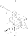
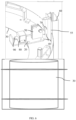
- FIG. 1 is a schematic representation of a landing lever assembly (10) of a pneumatic vacuum elevator in accordance with an embodiment of the present disclosure.
- the landing lever assembly (10) includes a landing lever plate (20) mechanically coupled to a roof of an elevator cabin (30).
- the landing lever plate (20) is a base plate of the assembly (10), where the assembly (10) is arranged on the landing lever plate (20) to lock the elevator cabin (30) in a pneumatic vacuum elevator cylinder.
- the assembly (10) includes a locking plate (40) mechanically coupled to the landing lever plate (20) using support plates (50).
- the locking plate (40) may include a triangular shape.
- the locking plate (40) may be composed of metal.
- the locking plate (40) may be rested on a guide rail (55) in an elevator cylinder assembly (60) via a cut-out (70).
- the locking plate (40) is provided to support the elevator cabin (30) independently of the hoisting mechanism while the load transfer is being affected.
- the locking plate (40) prevents the elevator cabin (30) descending when the brake does not hold, the power is insufficient or, in case of traction elevators, when the traction is insufficient.
- the assembly (10) includes a solenoid valve (80), where bottom side of the solenoidal valve (80) is disposed on the landing lever plate (20).
- the solenoid valve (80) includes a hollow portion which is adapted to receive a guide pin (90) via two holes (95) on each side of the solenoid valve (80).
- the solenoid valve (80) may use power to engage the locking plate (40).
- the locking plate (40) does not require power to have it released.
- the locking plate (40) is mechanically coupled to the solenoid valve (80) using the guide pin (90).
- the solenoid valve (80) and the guide pin (90) may be composed of metal.
- the guide pin (90) actuates the locking plate (40) by sliding within the solenoid valve (80), in at least one mode, based on an activation signal received from a magnetic sensor (not shown in FIG. 1 ).
- the magnetic sensor is coupled to the guide pin (90), where the magnetic sensor is placed on an external cylinder at each landing position.
- the at least one operational mode may include a lock applied condition or a lock released condition.
- the guide pin (90) slides within the solenoid valve (80) and actuate the locking plate (40) in at least one direction depending upon the action of the elevator cabin (30) to lock or release the elevator cabin (30) with the guide rail (55).
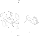
- FIG. 2 is a schematic representation of an exploded view of the landing lever assembly (10) of FIG. 1 , depicting position of various components in the landing lever assembly (10) in accordance with an embodiment of the present disclosure.
- the landing lever assembly (10) includes the landing lever plate (20) which act as a base for the assembly (10).
- the assembly (10) also includes support plates (50).
- the support plates (50) may two support plates.
- the support plates (50) are coupled together using at least two intermediate plates (100), where the at least two intermediate plates (100) are arranged in between the two support plates (50).
- Each of the support plate (50) includes a hole (110).
- the assembly (10) also includes the locking plate (40) which is coupled to the support plates (50) using a hex bolt (120), at least two washers (130) and a locking nut (140) passed through the holes (110) of the support plates (50).
- the locknut (130) may include a hex nyloc nut.
- the nyloc nut may include a nyloninsert lock nut, polymer-insert lock nut, or elastic stop nut.
- the nyloc nut is a kind of locknut with a nylon collar that increases friction on the screw thread.
- the assembly (10) includes the solenoid valve (80) which is coupled to the bottom of the landing lever plate (20) using multiple screws (150).
- the solenoid valve (50) may be coupled to the landing lever plate (20) using four pan head screws.
- the pan head screws are machine screws with heads that are flat on top and rounded on the sides.
- the solenoid valve (80) includes two holes (160) on each on left and right side of the solenoid valve (80). The two holes (160) are adapted to receive the guide pin (90).
- the guide pin (90) may slide within the solenoid valve (80) based on the activation signal received from the magnetic sensor.
- One end of the guide pin (90) is coupled to the locking plate (40).
- the guide pin (90) slides within the solenoid valve (80) upon receiving the activation signal to actuate the locking plate (40) to control the movement of the elevator cabin (30).
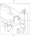
- FIG. 3 is a schematic representation of one embodiment (205) of the landing lever assembly (10) of FIG. 1 in accordance with an embodiment of the present disclosure.
- FIG. 3(a) shows an exploded view of landing lever plate weldment with aligning position
- FIG. 3(b) shows an assembled view of landing lever plate weldment with fixed position.
- the assembly (10) includes a landing lever plate (20), where the landing lever plate (20) includes a first portion (170) and a second portion (180).
- the first portion (170) is broader than the second portion (180).
- the first portion (180) includes two slots (190) of a first predefined size.
- the assembly (10) also includes two support plates (50), where each of the support plate (50) includes a protrusion (200).
- the two slots (190) of the landing lever plate (20) are adapted to receive respectively protrusions (200) of the support plates (50).
- the two support plates (50) accommodate at least two intermediate plates (100) to create a spacing between the two support plates (50). The spacing between the two support plates (50) enable the locking plate (40) to move in predefined directions.
- the second portion (180) of the landing lever plate (20) includes four slots (210) of a second predefined size.
- the assembly (10) includes the solenoid valve (80) which is fixed in the four slots (210) of the landing lever plate (20).
- the second portion (180) of the landing lever plate (20) includes a side plate (220) which is coupled at the end of the landing lever plate (20).
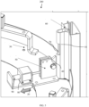
- FIG. 4 is a schematic representation of functional view (230) of the landing lever assembly (10) of FIG. 1 , depicting operation of the landing lever assembly (10) in locking condition in accordance with an embodiment of the present disclosure.
- the magnetic sensor senses this condition and generates the activation signal.
- the activation signal is provided to the guide pin (90) which slides within the solenoid valve (80) in a forward direction.
- the movement of the guide pin (90) in the forward direction actuates the locking plate (40) in a forward direction which then rest on the cut-out (70) of the guide rail (55) in the elevator cylinder assembly (75) and lock the elevator cabin (30).
- FIG. 5 is a schematic representation of functional view (250) of the landing lever assembly (10) of FIG. 1 , depicting operation of the landing lever assembly (10) in unlocking condition in accordance with an embodiment of the present disclosure.
- the magnetic sensor senses this condition and generates the activation signal.
- the activation signal is provided to the guide pin (90) which slides within the solenoid valve (80) in a backward direction.
- the movement of the guide pin (90) in the backward direction actuates the locking plate (40) in a backward direction which then removed from the cut-out (70) of the guide rail (55) in the elevator cylinder assembly (75) and release the elevator cabin (30).
- FIG. 6 is a schematic representation of the pneumatic vacuum elevator (260) in accordance with an embodiment of the present disclosure.
- the pneumatic vacuum elevator (260) includes an elevator cabin (30) to carry one or more users between one or more levels of a structure.
- the structure may include building, vessel or the like.
- the elevator (260) also includes a landing lever assembly (10) mechanically coupled to the elevator cabin (30).
- the landing lever assembly (10) includes a landing lever plate (20) coupled on a roof of an elevator cabin (30).
- the assembly (10) also includes a locking plate (40) coupled to the landing lever plate (20) using support plates (50).
- the assembly (10) further includes a solenoid valve (80) disposed on the landing lever plate (20) and mechanically coupled to the locking plate (40) using a guide pin (90), where the guide pin (90) actuates the locking plate (40) by sliding within the solenoid valve (80), in at least one operational mode, based on an activation signal received from a magnetic sensor.
- a solenoid valve (80) disposed on the landing lever plate (20) and mechanically coupled to the locking plate (40) using a guide pin (90), where the guide pin (90) actuates the locking plate (40) by sliding within the solenoid valve (80), in at least one operational mode, based on an activation signal received from a magnetic sensor.
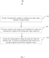
- FIG. 7 is a flow chart representing the steps involved in method (300) for operating the landing lever assembly in accordance with an embodiment of the present disclosure.
- the method (300) includes providing a locking plate coupled to a landing lever plate using support plates in step 310.
- the support plates may be coupled to the landing lever plate using at least two intermediate plates arranged in between the support plates.
- the locking plate may be coupled to the support plates using a hex bolt, at least two washers and a locking nut.
- the method (300) also includes providing a solenoid valve disposed on the landing lever plate and mechanically coupled to the locking plate using a guide pin in step 320.
- the solenoid valve is coupled to the landing lever plate using screws.
- the solenoid valve includes two holes on each on left and right side of the solenoid valve. The two holes are adapted to receive the guide pin.
- the guide pin and the solenoid valve may be composed of metal.
- the method (300) includes actuating the locking plate by sliding the guide pin within the solenoid valve, in at least one operational mode, based on an activation signal received from a magnetic sensor in step 330.
- the at least one operational mode may include a lock applied condition or a lock released condition.
- actuating the locking plate may include actuating the locking plate in a forward direction by sliding the guide pin in the forward direction based on an activation signal received from a magnetic sensor.
- actuating the locking plate may include actuating the locking plate in a backward direction by sliding the guide pin in the backward direction based on an activation signal received from a magnetic sensor.
- Various embodiments of the landing lever assembly as described above enables safety lock for an enclosed pneumatic vacuum elevator cabin provides a simple mechanism for setting the elevator landing door safety locking plate.
- the landing lever assembly allows control over the energy supplied to the motor and so enabled the elevator to be accurately positioned
Landscapes
- Engineering & Computer Science (AREA)
- Automation & Control Theory (AREA)
- Computer Networks & Wireless Communication (AREA)
- Structural Engineering (AREA)
- Elevator Control (AREA)
- Lift-Guide Devices, And Elevator Ropes And Cables (AREA)
Claims (6)
- Pneumatischer Vakuumaufzug (260), umfassend:eine Aufzugskabine (30), die darauf ausgelegt ist, einen oder mehrere Benutzer zwischen einer oder mehreren Etagen eines Bauwerks zu befördern;einen Zylinder des pneumatischen Vakuumaufzugs (60);eine Landehebelanordnung (10), die mechanisch mit der Aufzugskabine (30) gekuppelt ist, wobei die Landehebelanordnung (10) Folgendes umfasst:eine Landehebelplatte (20), die auf einem Dach der Aufzugskabine (30) gekuppelt ist ;eine Vielzahl von Trägerplatten (50);eine Verriegelungsplatte (40), die mit Hilfe der Vielzahl von Trägerplatten (50) mit der Landehebelplatte (20) gekuppelt ist;einen Führungsstift (90); undein Magnetventil (80), das auf der Landehebelplatte (20) angeordnet und mit Hilfe des Führungsstifts (90) mechanisch mit der Verriegelungsplatte (40) gekuppelt ist,wobei der Führungsstift (90) darauf ausgelegt ist, die Verriegelungsplatte (40) durch Verschieben im Inneren des Magnetventils (80) in mindestens einem Betriebsmodus zu betätigen,dadurch gekennzeichnet, dass der pneumatische Vakuumaufzug (260) einen Magnetsensor weiter umfasst, der an jeder Landeposition auf der Aufzugzylinderanordnung (60) platziert und mit dem Führungsstift (90) gekuppelt ist;wobei der Führungsstift (90) darauf ausgelegt ist, die Verriegelungsplatte (40) basierend auf einem von dem Magnetsensor empfangenen Aktivierungssignal zu betätigen;wobei der genannte Führungsstift (90) darauf ausgelegt ist:die Verriegelungsplatte (40) in einer Vorwärtsrichtung durch Verschieben des Führungsstifts (90) in der Vorwärtsrichtung basierend auf einem von dem Magnetsensor empfangenen Aktivierungssignal zu betätigen;die Verriegelungsplatte (40) in einer Rückwärtsrichtung durch Verschieben des Führungsstifts (90) in der Rückwärtsrichtung basierend auf einem von dem Magnetsensor empfangenen Aktivierungssignal zu betätigen.
- Anordnung (10) nach Anspruch 1, wobei die Verriegelungsplatte (40) über eine Aussparung (70) auf einer Führungsschiene (55) in der Aufzugzylinderanordnung (60) gelagert ist.
- Anordnung (10) nach Anspruch 1, wobei die Verriegelungsplatte (40) mit Hilfe einer Sechskantschraube (120), mindestens zwei Unterlegscheiben (130) und einer Sicherungsmutter (140) mit der Vielzahl von Trägerplatten (50) gekuppelt ist.
- Anordnung (10) nach Anspruch 1, wobei das Magnetventil (80) mit Hilfe einer Vielzahl von Schrauben (150) mit der Landehebelplatte (20) gekuppelt ist.
- Anordnung (10) nach Anspruch 1, wobei das Magnetventil (80) Energie benötigt, um die Verriegelungsplatte (40) während des Verriegelungsvorgangs in Eingriff zu bringen, wobei die Energie für den Entriegelungsvorgang nicht benötigt wird.
- Verfahren (300), umfassend:Bereitstellung einer Aufzugskabine (30), die darauf ausgelegt ist, einen oder mehrere Benutzer zwischen einer oder mehreren Etagen eines Bauwerks zu befördern;Bereitstellung eines Zylinders des pneumatischen Vakuumaufzugs (60);Bereitstellung einer Landehebelplatte (20), die auf einem Dach der Aufzugskabine (30) gekuppelt ist;(310) Bereitstellung einer Verriegelungsplatte (40), die mit Hilfe einer Vielzahl von Trägerplatten (50) mit der Landehebelplatte (20) gekuppelt ist;(320) Bereitstellung eines Magnetventils (80), das auf der Landehebelplatte (20) angeordnet und mit Hilfe eines Führungsstifts (90) mechanisch mit der Verriegelungsplatte (40) gekuppelt ist; und(330) Betätigung der Verriegelungsplatte (40) durch Verschieben des Führungsstifts (90) im Inneren des Magnetventils (80) in mindestens einer Betriebsart,dadurch gekennzeichnet, dass ein Magnetsensor bereitgestellt wird, der an jeder Landeposition auf der Aufzugzylinderanordnung (60) positioniert und mit dem Führungsstift (90) gekuppelt ist;und dadurch, dass die Betätigung der Verriegelungsplatte auf einem von dem Magnetsensor empfangenen Aktivierungssignal basiert;wobei die Betätigung der Verriegelungsplatte Folgendes umfasst:Betätigen der Verriegelungsplatte (40) in einer Vorwärtsrichtung durch Verschieben des Führungsstifts (90) in der Vorwärtsrichtung basierend auf einem von dem Magnetsensor empfangenen Aktivierungssignal;Betätigen der Verriegelungsplatte (40) in einer Rückwärtsrichtung durch Verschieben des Führungsstifts (90) in der Rückwärtsrichtung basierend auf einem von dem Magnetsensor empfangenen Aktivierungssignal.
Applications Claiming Priority (2)
| Application Number | Priority Date | Filing Date | Title |
|---|---|---|---|
| IN202041023083 | 2020-06-02 | ||
| PCT/IB2020/058444 WO2021245456A1 (en) | 2020-06-02 | 2020-09-11 | Landing lever assembly of a pneumatic vacuum elevator and method to operate the same |
Publications (4)
| Publication Number | Publication Date |
|---|---|
| EP4157777A1 EP4157777A1 (de) | 2023-04-05 |
| EP4157777A4 EP4157777A4 (de) | 2024-06-19 |
| EP4157777C0 EP4157777C0 (de) | 2025-05-07 |
| EP4157777B1 true EP4157777B1 (de) | 2025-05-07 |
Family
ID=78830148
Family Applications (1)
| Application Number | Title | Priority Date | Filing Date |
|---|---|---|---|
| EP20939098.8A Active EP4157777B1 (de) | 2020-06-02 | 2020-09-11 | Landehebelanordnung eines pneumatischen vakuumaufzugs und verfahren zum betrieb davon |
Country Status (6)
| Country | Link |
|---|---|
| US (1) | US11807494B2 (de) |
| EP (1) | EP4157777B1 (de) |
| AU (1) | AU2020451874B2 (de) |
| CA (1) | CA3181097A1 (de) |
| ES (1) | ES3035082T3 (de) |
| WO (1) | WO2021245456A1 (de) |
Families Citing this family (1)
| Publication number | Priority date | Publication date | Assignee | Title |
|---|---|---|---|---|
| US12264039B2 (en) * | 2023-02-01 | 2025-04-01 | Ruphavathy Vishal | Suspension arrangement to absorb stress acting on an elevator cabin during landing |
Family Cites Families (6)
| Publication number | Priority date | Publication date | Assignee | Title |
|---|---|---|---|---|
| US5583326A (en) * | 1992-01-08 | 1996-12-10 | Sors Carlos Alberto | Pneumatic elevator by depressure |
| UY23516A1 (es) | 1992-01-08 | 1993-03-30 | Sors Carlos Alberto | Ascensor neumático por depresión |
| US6085873A (en) * | 1999-05-27 | 2000-07-11 | Macchi; Anselmo John | Pneumatic elevator |
| KR101160644B1 (ko) | 2011-06-17 | 2012-06-28 | 전귀동 | 공압을 이용한 엘리베이터 |
| CN103693529A (zh) * | 2013-02-01 | 2014-04-02 | 苏州天梭电梯有限公司 | 气动真空升降机 |
| CN104401851B (zh) | 2014-11-25 | 2017-02-01 | 昆山通祐电梯有限公司 | 一种多层真空气动电梯 |
-
2020
- 2020-09-11 AU AU2020451874A patent/AU2020451874B2/en active Active
- 2020-09-11 ES ES20939098T patent/ES3035082T3/es active Active
- 2020-09-11 WO PCT/IB2020/058444 patent/WO2021245456A1/en not_active Ceased
- 2020-09-11 US US17/928,624 patent/US11807494B2/en active Active
- 2020-09-11 EP EP20939098.8A patent/EP4157777B1/de active Active
- 2020-09-11 CA CA3181097A patent/CA3181097A1/en active Pending
Also Published As
| Publication number | Publication date |
|---|---|
| US11807494B2 (en) | 2023-11-07 |
| EP4157777A1 (de) | 2023-04-05 |
| AU2020451874B2 (en) | 2025-05-22 |
| US20230137945A1 (en) | 2023-05-04 |
| AU2020451874A1 (en) | 2023-01-19 |
| WO2021245456A1 (en) | 2021-12-09 |
| ES3035082T3 (en) | 2025-08-28 |
| EP4157777A4 (de) | 2024-06-19 |
| EP4157777C0 (de) | 2025-05-07 |
| CA3181097A1 (en) | 2021-12-09 |
Similar Documents
| Publication | Publication Date | Title |
|---|---|---|
| US8297411B2 (en) | Brake device for use in an elevator using a target pattern when a hoist is not driven | |
| EP3677534B1 (de) | Aktor einer sicherheitsvorrichtung eines aufzugs | |
| CN102459049A (zh) | 电梯装置 | |
| USRE38835E1 (en) | Remote brake release mechanism for an elevator machine | |
| KR20080023181A (ko) | 승강 설비의 작동 방법, 이 방법으로 작동가능한 승강 설비및 이 승강 설비를 위한 안전 장치 | |
| EP2763925A1 (de) | Aufzugbremssteuerung | |
| EP4157777B1 (de) | Landehebelanordnung eines pneumatischen vakuumaufzugs und verfahren zum betrieb davon | |
| JP2004224492A (ja) | エレベータ装置 | |
| EP2090540B1 (de) | Aufzugssystem | |
| JP2005239329A (ja) | エレベーターの保守作業用管制装置 | |
| AU2019406965B2 (en) | Lift system arrangement with a lift brake device | |
| CN108861965B (zh) | 同时进行的电梯轿厢安全装置和配重安全装置致动 | |
| EP1724225B1 (de) | Notbremsvorrichtung für einen aufzug | |
| EP2436635A1 (de) | Aufzugsvorrichtung | |
| JP2000143115A (ja) | エレベーターの故障時救出運転装置 | |
| JP2566855Y2 (ja) | ロープレスエレベータの制動装置 | |
| AU2020289772A1 (en) | System and method to operate a pneumatic vacuum elevator | |
| EP4157776B1 (de) | Bremsanordnung für einen pneumatischen vakuumaufzug und verfahren zum betrieb davon | |
| EP4349757A1 (de) | Notstoppvorrichtung, aufzug und verfahren zur wiederherstellung einer notstoppvorrichtung | |
| JP2012066907A (ja) | エレベーターの制動装置及びそれを用いたエレベーター装置 | |
| CN111448156B (zh) | 用于行驶体的防坠装置、具有防坠装置的电梯设备以及用于将防坠装置解除卡锁的方法 | |
| KR100727197B1 (ko) | 엘리베이터 제어장치 | |
| CN120322401A (zh) | 电梯以及紧急制动装置的复位方法 | |
| JPH0958947A (ja) | リニアモータ方式エレベータの制御装置 | |
| JPH09323872A (ja) | エレベータ秤装置の点検方法及びその点検装置 |
Legal Events
| Date | Code | Title | Description |
|---|---|---|---|
| STAA | Information on the status of an ep patent application or granted ep patent |
Free format text: STATUS: THE INTERNATIONAL PUBLICATION HAS BEEN MADE |
|
| PUAI | Public reference made under article 153(3) epc to a published international application that has entered the european phase |
Free format text: ORIGINAL CODE: 0009012 |
|
| STAA | Information on the status of an ep patent application or granted ep patent |
Free format text: STATUS: REQUEST FOR EXAMINATION WAS MADE |
|
| 17P | Request for examination filed |
Effective date: 20221220 |
|
| AK | Designated contracting states |
Kind code of ref document: A1 Designated state(s): AL AT BE BG CH CY CZ DE DK EE ES FI FR GB GR HR HU IE IS IT LI LT LU LV MC MK MT NL NO PL PT RO RS SE SI SK SM TR |
|
| P01 | Opt-out of the competence of the unified patent court (upc) registered |
Effective date: 20230411 |
|
| DAV | Request for validation of the european patent (deleted) | ||
| DAX | Request for extension of the european patent (deleted) | ||
| A4 | Supplementary search report drawn up and despatched |
Effective date: 20240523 |
|
| RIC1 | Information provided on ipc code assigned before grant |
Ipc: B66B 17/34 20060101ALI20240516BHEP Ipc: B66B 9/04 20060101AFI20240516BHEP |
|
| GRAP | Despatch of communication of intention to grant a patent |
Free format text: ORIGINAL CODE: EPIDOSNIGR1 |
|
| STAA | Information on the status of an ep patent application or granted ep patent |
Free format text: STATUS: GRANT OF PATENT IS INTENDED |
|
| INTG | Intention to grant announced |
Effective date: 20250131 |
|
| GRAS | Grant fee paid |
Free format text: ORIGINAL CODE: EPIDOSNIGR3 |
|
| GRAA | (expected) grant |
Free format text: ORIGINAL CODE: 0009210 |
|
| STAA | Information on the status of an ep patent application or granted ep patent |
Free format text: STATUS: THE PATENT HAS BEEN GRANTED |
|
| AK | Designated contracting states |
Kind code of ref document: B1 Designated state(s): AL AT BE BG CH CY CZ DE DK EE ES FI FR GB GR HR HU IE IS IT LI LT LU LV MC MK MT NL NO PL PT RO RS SE SI SK SM TR |
|
| REG | Reference to a national code |
Ref country code: GB Ref legal event code: FG4D |
|
| REG | Reference to a national code |
Ref country code: CH Ref legal event code: EP |
|
| REG | Reference to a national code |
Ref country code: DE Ref legal event code: R096 Ref document number: 602020051115 Country of ref document: DE |
|
| REG | Reference to a national code |
Ref country code: IE Ref legal event code: FG4D |
|
| U01 | Request for unitary effect filed |
Effective date: 20250603 |
|
| U07 | Unitary effect registered |
Designated state(s): AT BE BG DE DK EE FI FR IT LT LU LV MT NL PT RO SE SI Effective date: 20250610 |
|
| P04 | Withdrawal of opt-out of the competence of the unified patent court (upc) registered |
Free format text: CASE NUMBER: APP_26682/2025 Effective date: 20250604 |
|
| REG | Reference to a national code |
Ref country code: ES Ref legal event code: FG2A Ref document number: 3035082 Country of ref document: ES Kind code of ref document: T3 Effective date: 20250828 |
|
| PG25 | Lapsed in a contracting state [announced via postgrant information from national office to epo] |
Ref country code: NO Free format text: LAPSE BECAUSE OF FAILURE TO SUBMIT A TRANSLATION OF THE DESCRIPTION OR TO PAY THE FEE WITHIN THE PRESCRIBED TIME-LIMIT Effective date: 20250807 Ref country code: GR Free format text: LAPSE BECAUSE OF FAILURE TO SUBMIT A TRANSLATION OF THE DESCRIPTION OR TO PAY THE FEE WITHIN THE PRESCRIBED TIME-LIMIT Effective date: 20250808 |
|
| PG25 | Lapsed in a contracting state [announced via postgrant information from national office to epo] |
Ref country code: PL Free format text: LAPSE BECAUSE OF FAILURE TO SUBMIT A TRANSLATION OF THE DESCRIPTION OR TO PAY THE FEE WITHIN THE PRESCRIBED TIME-LIMIT Effective date: 20250507 |
|
| PGFP | Annual fee paid to national office [announced via postgrant information from national office to epo] |
Ref country code: GB Payment date: 20250915 Year of fee payment: 6 |
|
| PG25 | Lapsed in a contracting state [announced via postgrant information from national office to epo] |
Ref country code: HR Free format text: LAPSE BECAUSE OF FAILURE TO SUBMIT A TRANSLATION OF THE DESCRIPTION OR TO PAY THE FEE WITHIN THE PRESCRIBED TIME-LIMIT Effective date: 20250507 |
|
| PG25 | Lapsed in a contracting state [announced via postgrant information from national office to epo] |
Ref country code: RS Free format text: LAPSE BECAUSE OF FAILURE TO SUBMIT A TRANSLATION OF THE DESCRIPTION OR TO PAY THE FEE WITHIN THE PRESCRIBED TIME-LIMIT Effective date: 20250807 |
|
| PG25 | Lapsed in a contracting state [announced via postgrant information from national office to epo] |
Ref country code: IS Free format text: LAPSE BECAUSE OF FAILURE TO SUBMIT A TRANSLATION OF THE DESCRIPTION OR TO PAY THE FEE WITHIN THE PRESCRIBED TIME-LIMIT Effective date: 20250907 |
|
| U20 | Renewal fee for the european patent with unitary effect paid |
Year of fee payment: 6 Effective date: 20250930 |
|
| PG25 | Lapsed in a contracting state [announced via postgrant information from national office to epo] |
Ref country code: SM Free format text: LAPSE BECAUSE OF FAILURE TO SUBMIT A TRANSLATION OF THE DESCRIPTION OR TO PAY THE FEE WITHIN THE PRESCRIBED TIME-LIMIT Effective date: 20250507 |
|
| PG25 | Lapsed in a contracting state [announced via postgrant information from national office to epo] |
Ref country code: CZ Free format text: LAPSE BECAUSE OF FAILURE TO SUBMIT A TRANSLATION OF THE DESCRIPTION OR TO PAY THE FEE WITHIN THE PRESCRIBED TIME-LIMIT Effective date: 20250507 |
|
| PG25 | Lapsed in a contracting state [announced via postgrant information from national office to epo] |
Ref country code: SK Free format text: LAPSE BECAUSE OF FAILURE TO SUBMIT A TRANSLATION OF THE DESCRIPTION OR TO PAY THE FEE WITHIN THE PRESCRIBED TIME-LIMIT Effective date: 20250507 |
|
| PGFP | Annual fee paid to national office [announced via postgrant information from national office to epo] |
Ref country code: ES Payment date: 20251002 Year of fee payment: 6 |