EP4157752B1 - Lagersystem für eine fabrik zur herstellung von brettern - Google Patents
Lagersystem für eine fabrik zur herstellung von brettern Download PDFInfo
- Publication number
- EP4157752B1 EP4157752B1 EP21732816.0A EP21732816A EP4157752B1 EP 4157752 B1 EP4157752 B1 EP 4157752B1 EP 21732816 A EP21732816 A EP 21732816A EP 4157752 B1 EP4157752 B1 EP 4157752B1
- Authority
- EP
- European Patent Office
- Prior art keywords
- rail
- wagon
- storage system
- longitudinal
- main wagon
- Prior art date
- Legal status (The legal status is an assumption and is not a legal conclusion. Google has not performed a legal analysis and makes no representation as to the accuracy of the status listed.)
- Active
Links
Images


Classifications
-
- B—PERFORMING OPERATIONS; TRANSPORTING
- B65—CONVEYING; PACKING; STORING; HANDLING THIN OR FILAMENTARY MATERIAL
- B65G—TRANSPORT OR STORAGE DEVICES, e.g. CONVEYORS FOR LOADING OR TIPPING, SHOP CONVEYOR SYSTEMS OR PNEUMATIC TUBE CONVEYORS
- B65G47/00—Article or material-handling devices associated with conveyors; Methods employing such devices
- B65G47/52—Devices for transferring articles or materials between conveyors i.e. discharging or feeding devices
- B65G47/53—Devices for transferring articles or materials between conveyors i.e. discharging or feeding devices between conveyors which cross one another
-
- B—PERFORMING OPERATIONS; TRANSPORTING
- B65—CONVEYING; PACKING; STORING; HANDLING THIN OR FILAMENTARY MATERIAL
- B65G—TRANSPORT OR STORAGE DEVICES, e.g. CONVEYORS FOR LOADING OR TIPPING, SHOP CONVEYOR SYSTEMS OR PNEUMATIC TUBE CONVEYORS
- B65G1/00—Storing articles, individually or in orderly arrangement, in warehouses or magazines
- B65G1/02—Storage devices
- B65G1/04—Storage devices mechanical
- B65G1/0407—Storage devices mechanical using stacker cranes
- B65G1/0414—Storage devices mechanical using stacker cranes provided with satellite cars adapted to travel in storage racks
-
- B—PERFORMING OPERATIONS; TRANSPORTING
- B65—CONVEYING; PACKING; STORING; HANDLING THIN OR FILAMENTARY MATERIAL
- B65G—TRANSPORT OR STORAGE DEVICES, e.g. CONVEYORS FOR LOADING OR TIPPING, SHOP CONVEYOR SYSTEMS OR PNEUMATIC TUBE CONVEYORS
- B65G1/00—Storing articles, individually or in orderly arrangement, in warehouses or magazines
- B65G1/02—Storage devices
- B65G1/04—Storage devices mechanical
- B65G1/0492—Storage devices mechanical with cars adapted to travel in storage aisles
-
- B—PERFORMING OPERATIONS; TRANSPORTING
- B65—CONVEYING; PACKING; STORING; HANDLING THIN OR FILAMENTARY MATERIAL
- B65G—TRANSPORT OR STORAGE DEVICES, e.g. CONVEYORS FOR LOADING OR TIPPING, SHOP CONVEYOR SYSTEMS OR PNEUMATIC TUBE CONVEYORS
- B65G35/00—Mechanical conveyors not otherwise provided for
- B65G35/06—Mechanical conveyors not otherwise provided for comprising a load-carrier moving along a path, e.g. a closed path, and adapted to be engaged by any one of a series of traction elements spaced along the path
-
- B—PERFORMING OPERATIONS; TRANSPORTING
- B65—CONVEYING; PACKING; STORING; HANDLING THIN OR FILAMENTARY MATERIAL
- B65G—TRANSPORT OR STORAGE DEVICES, e.g. CONVEYORS FOR LOADING OR TIPPING, SHOP CONVEYOR SYSTEMS OR PNEUMATIC TUBE CONVEYORS
- B65G2201/00—Indexing codes relating to handling devices, e.g. conveyors, characterised by the type of product or load being conveyed or handled
- B65G2201/02—Articles
- B65G2201/0214—Articles of special size, shape or weigh
- B65G2201/022—Flat
-
- B—PERFORMING OPERATIONS; TRANSPORTING
- B65—CONVEYING; PACKING; STORING; HANDLING THIN OR FILAMENTARY MATERIAL
- B65G—TRANSPORT OR STORAGE DEVICES, e.g. CONVEYORS FOR LOADING OR TIPPING, SHOP CONVEYOR SYSTEMS OR PNEUMATIC TUBE CONVEYORS
- B65G2201/00—Indexing codes relating to handling devices, e.g. conveyors, characterised by the type of product or load being conveyed or handled
- B65G2201/02—Articles
- B65G2201/0282—Wooden articles, e.g. logs, trunks or planks
Definitions
- the object of the invention is a storage system for use in factories fabricating boards, especially particle boards, OSB boards or MDF boards, the storage system comprising rails in the longitudinal direction of the storage and rails in the crosswise direction of the storage as well as at least one satellite wagon pair that is arranged to move along longitudinal rails, and at least one main wagon that is arranged to move along the crosswise rails by means of rail wheels installed on the main wagon, the main wagon comprising two longitudinal rail pairs for a satellite wagon pair.
- the invention thus relates to a storage system for use in factories fabricating boards, especially particle boards, OSB boards and MDF boards, in which large board stacks are stored temporarily.
- wood-based boards manufactured on a continuous-action press line are stored for a certain time in intermediate storage before the downstream work phases, such as sanding and sawing.
- the storage is also used for storing different grades of boards.
- the typical mass of large stacks in factories fabricating particle boards, OSB boards and MDF boards is 40-80 tonnes.
- the typical stack height is 3-5 m, width 1.8-3.6 m and length 5-9 m.
- the stacks in the storage system that is the object of the invention are transported on two wagons running on rails under the stack in the longitudinal direction of the storage, the wagons transferring a stack to rows of the storage resting on three longitudinal supports. These wagons moving in the longitudinal direction are herein called satellite wagons and they always operate in pairs.
- the transfer of stacks to a storage row and the fetching of stacks from a storage row occurs in such a way that a satellite wagon pair lifts a stack from the bottom surface of the stack, such that the stack detaches from its longitudinal supports, and transports the stack to a storage row and lowers the stack onto the longitudinal supports in the storage or, when fetching from the storage, onto the supports on the main wagon (i.e. the crosswise wagon).
- the moving of a satellite wagon pair in a crosswise direction i.e. from one longitudinal row to another longitudinal row, occurs by driving the satellite wagon pair onto the main wagon, which then transports the satellite wagon pair to the next worksite, i.e. to some other longitudinal row.
- S49 36075 A discloses a storage system with the features of the preamble of claim 1.
- a main wagon according to what is known in the art is a large welded structure that, owing to its size, is not transportable in an ordinary shipping container. This, of course, results in higher transportation costs and limits the opportunities for selecting the cheapest manufacturing location.
- the aim of the present invention is to provide a new type of storage system for large stacks, wherein the operational height dimension of the main wagon, i.e. the crosswise wagon, is as small as possible so that the height position of the longitudinal rails of the storage area in relation to the crosswise rails of the storage (on which the main wagon travels) would be as low as possible, and the height and volume of the steel and/or concrete structure of the storage area as small as possible.
- the main wagon comprises at the point of at least one crosswise rail at least three rail wheels resting on the rail in question.
- the invention can be implemented in such a way that at the point of each crosswise rail the main wagon has at least three rail wheels resting on the rail. Of these three rail wheels resting on the crosswise rail, the centermost can be situated between the two centermost longitudinal rails on the main wagon. In one embodiment of the invention, the centermost of the three rail wheels resting on a crosswise rail is situated essentially on the longitudinal center line of the main wagon.
- One of the advantages of the invention that can be mentioned is that it significantly reduces the material requirements of the storage system structure because the operational height dimension is smaller than previously. The construction costs of a storage with a large surface area will therefore remain lower than previously.
- the main wagon comprises two parts of essentially the same size connected to each other, one advantage is that the parts will fit into a standard shipping container. That being the case, also transportation costs are reduced.
- two wheels of smaller diameter can be arranged. These wheels of a smaller diameter are preferably arranged with pivoted or flexible bogie suspension to bear an essentially equal load.
- the main wagon can be implemented in such a way that it comprises two frame modules, the joint face between the modules being between the two centermost rails in the direction of movement of the main wagon.
- the main wagon comprises two frame modules, the joint face between the modules being essentially on the longitudinal center line of the main wagon.
- Fig. 1 thus presents an overview of a storage system for a factory fabricating particle boards, OSB boards and MDF boards.
- the board stacks three of which are seen here, are marked with the reference number 1. There can, of course, be more board stacks but for the sake of clarity not all are presented.
- the board stack at the bottom edge of Fig. 1 is on top of a wagon moving in a crosswise direction, i.e. the main wagon 2.
- the main wagon moves along rails 3. This direction of movement is therefore called the crosswise direction.
- Fig. 1 presents three longitudinal storage rows 8, each of which is formed from three longitudinal supports 9. There can, of course, be considerably more of these storage rows 8 than three. Additionally, they can be on both sides of the main wagon 2. They are presented here now only on the left-hand side of the main wagon 2 when looking at the figure.
- Fig. 1 also presents a second pair of satellite wagons, which can be seen slightly under the stack 1 on the left-hand side.
- the main wagon 2 can therefore be arranged to serve more than one satellite wagon pair 10.
- This second satellite wagon pair is not necessarily needed but, particularly in very large storages, it adds capacity.
- a satellite wagon pair 10' can also be seen, which can be a back-up. In other words, from it one satellite wagon 10' or both satellite wagons 10' are taken into use if a defect occurs in the regular satellite wagons 10 or if they otherwise need servicing. In the storage system, commissioning of the replacement satellite wagon 10' is easy without requiring installation work or connection work.
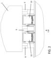
- the centermost rail wheels 12' are situated in the case of Fig. 4 between the two centermost longitudinal rails 11 on the main wagon 2. It is also possible that the centermost rail wheel 12' of the three rail wheels 12, 12' resting on a crosswise rail 3 is situated essentially on the longitudinal center line of the main wagon 2.
- the main wagon 2 is assembled from two frame modules 2', 2'' that are fastened to each other at the installation site with some fastening method, such as by welding or with a bolted joint.
- the joint face between these frame modules 2', 2'' is between the two centermost rails in the direction of movement of the main wagon 2, and possibly on essentially the longitudinal center line of the main wagon, as in the solution according to Fig. 4 .
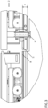
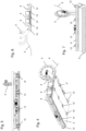
- Figs. 5-7 further present a main wagon according to the invention, as viewed from different directions.
- Fig. 8 presents a partly exploded view of the main wagon 2 according to the invention.
- the main wagon 2 thus comprises two frame modules 2' and 2''.
- the centermost rail wheels are fastened to the frame module 2' and in the other frame module are corresponding grooves for fitting them.
- the supports 9, of which there are three units, of the board stacks 1 are marked with the reference number 9.
- the longitudinal rails 11 of a satellite wagon pair are installed between them.
- the frame of the main wagon can comprise two steel plates 14', 14'' on the horizontal plane arranged at a distance from each other as well as two longitudinal and transverse web plates 15, 16 installed between them.
- Fig. 10 in the longitudinal web plates 15 of the frame of the main wagon is at least one aperture for bringing in an electric cable 17 from below the longitudinal rail 11 (the longitudinal rails 11 are not visible in Fig. 10 , but their location can be seen from Fig. 9 ).
Landscapes
- Engineering & Computer Science (AREA)
- Mechanical Engineering (AREA)
- Warehouses Or Storage Devices (AREA)
- Handcart (AREA)
Claims (10)
- Lagersystem zur Verwendung in Fabriken, die Platten, insbesondere Spanplatten, OSB-Platten oder MDF-Platten herstellen, wobei das Lagersystem Folgendes umfasst: Längsschienen (8) des Lagers und Querschienen (3) des Lagers sowie mindestens ein Satellitenwagenpaar (10), das so angeordnet ist, dass es sich entlang der Längsschienen (8) bewegt, und mindestens einen Hauptwagen (2), der so angeordnet ist, dass er sich entlang der Querschienen (3) mittels Schienenrädern (12) bewegt, die an dem Hauptwagen (2) angebracht sind, wobei der Hauptwagen (2) zwei Längsschienenpaare (11) für ein Satellitenwagenpaar umfasst, dadurch gekennzeichnet, dass der Hauptwagen (2) an der Stelle mindestens einer Querschiene (3) mindestens drei Schienenräder (12, 12') aufweist, die in der Längsrichtung nacheinander auf der Oberseite der betreffenden Schiene (3) aufliegen.
- Lagersystem nach Anspruch 1, dadurch gekennzeichnet, dass der Hauptwagen (2) an der Stelle jeder Querschiene (3) mindestens drei Schienenräder (12, 12') aufweist, die auf der Schiene (3) aufliegen.
- Lagersystem nach Anspruch 1 oder 2, dadurch gekennzeichnet, dass sich das mittigste Schienenrad (12') der drei nacheinander auf einer Querschiene (3) aufliegenden Schienenräder (12, 12') zwischen den beiden mittigsten Längsschienen (11) am Hauptwagen (2) befindet.
- Lagersystem nach einem der Ansprüche 1 bis 3,
dadurch gekennzeichnet, dass sich das mittigste Schienenrad (12') der drei auf einer Querschiene (3) aufliegenden Schienenräder (12') im Wesentlichen auf der Längsmittellinie des Hauptwagens (2) befindet. - Lagersystem nach einem der Ansprüche 1 bis 4,
dadurch gekennzeichnet, dass eines oder mehrere der Schienenräder (12, 12') zwei Räder mit einem kleineren Durchmesser als die anderen Schienenräder umfassen. - Lagersystem nach Anspruch 5, dadurch gekennzeichnet, dass die Räder mit kleinerem Durchmesser mit einer schwenkbaren oder flexiblen Drehgestellaufhängung angeordnet sind, um eine im Wesentlichen gleiche Last zu tragen.
- Lagersystem nach einem der Ansprüche 1 bis 6,
dadurch gekennzeichnet, dass der Hauptwagen (2) zwei Rahmenmodule (2', 2") umfasst, wobei die Stoßfläche zwischen den Modulen in Bewegungsrichtung des Hauptwagens (2) zwischen den beiden mittigsten Schienen (11) liegt. - Lagersystem nach einem der Ansprüche 1 bis 7,
dadurch gekennzeichnet, dass der Hauptwagen (2) zwei Rahmenmodule (2', 2") umfasst, wobei die Stoßfläche zwischen den Modulen im Wesentlichen auf der Längsmittellinie des Hauptwagens (2) liegt. - Lagersystem nach einem der Ansprüche 1 bis 8,
dadurch gekennzeichnet, dass der Rahmen des Hauptwagens (2) zwei Stahlbleche (14', 14"), die in der Horizontalebene in einem Abstand zueinander angeordnet sind, sowie zwei zwischen ihnen angebrachte Längs- und Querstegbleche (15, 16) umfasst. - Lagersystem nach Anspruch 9, dadurch gekennzeichnet, dass in den Längsstegblechen (15) des Rahmens des Hauptwagens (2) mindestens eine Öffnung zum Einführen eines elektrischen Kabels (17) von unterhalb der Längsschiene (11) vorhanden ist.
Applications Claiming Priority (2)
| Application Number | Priority Date | Filing Date | Title |
|---|---|---|---|
| FI20205562A FI20205562A1 (fi) | 2020-05-29 | 2020-05-29 | Lastu-, osb- ja mdf-levytehtaan varastojärjestelmä |
| PCT/EP2021/064468 WO2021240010A2 (en) | 2020-05-29 | 2021-05-29 | A storage system for a factory fabricating boards |
Publications (2)
| Publication Number | Publication Date |
|---|---|
| EP4157752A2 EP4157752A2 (de) | 2023-04-05 |
| EP4157752B1 true EP4157752B1 (de) | 2025-07-02 |
Family
ID=76483267
Family Applications (1)
| Application Number | Title | Priority Date | Filing Date |
|---|---|---|---|
| EP21732816.0A Active EP4157752B1 (de) | 2020-05-29 | 2021-05-29 | Lagersystem für eine fabrik zur herstellung von brettern |
Country Status (4)
| Country | Link |
|---|---|
| EP (1) | EP4157752B1 (de) |
| CN (1) | CN115697861B (de) |
| FI (1) | FI20205562A1 (de) |
| WO (1) | WO2021240010A2 (de) |
Families Citing this family (3)
| Publication number | Priority date | Publication date | Assignee | Title |
|---|---|---|---|---|
| CA3216934A1 (en) | 2022-10-27 | 2024-04-27 | Strothmann Machines & Handling GmbH | Storage facility for material panels |
| DE102022004022A1 (de) | 2022-10-27 | 2024-05-02 | Strothmann Machines & Handling GmbH | Lagereinrichtung für Werkstoffplatten |
| DE202022002880U1 (de) | 2022-10-27 | 2024-01-30 | Strothmann Machines & Handling GmbH | Lagereinrichtung für Werkstoffplatten |
Family Cites Families (9)
| Publication number | Priority date | Publication date | Assignee | Title |
|---|---|---|---|---|
| FR448963A (fr) * | 1912-12-18 | 1913-02-14 | Charles De Bange | Chemin de fer routier |
| JPS554642B2 (de) * | 1972-08-09 | 1980-01-31 | ||
| JPS6376774U (de) * | 1986-11-08 | 1988-05-21 | ||
| DE19626966A1 (de) * | 1996-07-04 | 1998-01-08 | Cegelec Aeg Anlagen Und Automa | Spurgeführtes Transportsystem mit Transportfahrzeugen |
| US8613582B2 (en) * | 2008-10-06 | 2013-12-24 | Unitronics Parking Solutions Ltd | Shuttle cars for use in automated parking |
| CN202429661U (zh) * | 2012-02-16 | 2012-09-12 | 云南鑫鼎建材有限公司 | 循环轨道运输系统 |
| NL2011058C2 (nl) * | 2013-06-28 | 2015-01-05 | Vanderlande Ind Bv | Systeem voor het opslaan van producthouders. |
| SE538973C2 (sv) * | 2013-12-10 | 2017-03-07 | Texo Application Ab | Hjulupphängning för skyttel, samt lagersystem med skyttel som är rörlig på skenor |
| CN110155171A (zh) * | 2019-04-30 | 2019-08-23 | 上海擎朗智能科技有限公司 | 一种车辆底盘、车辆及该车辆底盘的控制方法 |
-
2020
- 2020-05-29 FI FI20205562A patent/FI20205562A1/fi unknown
-
2021
- 2021-05-29 CN CN202180038771.8A patent/CN115697861B/zh active Active
- 2021-05-29 WO PCT/EP2021/064468 patent/WO2021240010A2/en not_active Ceased
- 2021-05-29 EP EP21732816.0A patent/EP4157752B1/de active Active
Also Published As
| Publication number | Publication date |
|---|---|
| CN115697861A (zh) | 2023-02-03 |
| WO2021240010A3 (en) | 2022-02-03 |
| EP4157752A2 (de) | 2023-04-05 |
| FI20205562A1 (fi) | 2021-11-30 |
| CN115697861B (zh) | 2025-10-03 |
| WO2021240010A2 (en) | 2021-12-02 |
Similar Documents
| Publication | Publication Date | Title |
|---|---|---|
| EP4157752B1 (de) | Lagersystem für eine fabrik zur herstellung von brettern | |
| US11794950B2 (en) | Structure for automated pallet storage and retrieval | |
| KR100843308B1 (ko) | 화물 자동화창고 | |
| US10207867B2 (en) | Automated pallet storage and retrieval system | |
| CN103662486A (zh) | 卷钢运输集装箱 | |
| NZ243085A (en) | Shelf system for storage and retrieval of rolls of material incorporating roll transporting system | |
| US8672148B2 (en) | Low profile push-back cart and push-back cart storage system | |
| US11131065B1 (en) | Rail system for a conveying vehicle and storage system | |
| EP4157753B1 (de) | Lagersystem zur verwendung in fabriken zur herstellung von platten, insbesondere osb, mdf oder spanplatten | |
| US7140503B2 (en) | Pushback cart storage system | |
| CN218859394U (zh) | 四向车轨道及具有其的货架 | |
| US5595311A (en) | Storage rack system | |
| CN115697758B (zh) | 一种在制造板的工厂中使用的用于存储板堆的存储系统 | |
| EP4161850B1 (de) | Lagersystem zum lagern von brettstapeln in lagerreihen zur verwendung in fabriken zur herstellung von brettern | |
| CN120457079A (zh) | 网格框架结构 | |
| US8082854B2 (en) | Chassis for a cable or pipeline trolley | |
| CN109110325B (zh) | 一种用于集装箱运输的自动扶梯桁架固定结构 | |
| CN218023492U (zh) | 货架及储物系统 | |
| CN217674783U (zh) | 一种仓储货架 | |
| CN223559749U (zh) | 一种运梁车车架结构 | |
| JP2022150796A (ja) | 搬送システム用構造体 | |
| CN203172626U (zh) | 电气盘柜运输装置 | |
| JP2000118628A (ja) | 自動倉庫のレールユニット | |
| WO2008019951A1 (de) | Hochregallager | |
| HK1125351B (en) | Chassis for a cable or pipeline trolley |
Legal Events
| Date | Code | Title | Description |
|---|---|---|---|
| STAA | Information on the status of an ep patent application or granted ep patent |
Free format text: STATUS: UNKNOWN |
|
| STAA | Information on the status of an ep patent application or granted ep patent |
Free format text: STATUS: THE INTERNATIONAL PUBLICATION HAS BEEN MADE |
|
| PUAI | Public reference made under article 153(3) epc to a published international application that has entered the european phase |
Free format text: ORIGINAL CODE: 0009012 |
|
| STAA | Information on the status of an ep patent application or granted ep patent |
Free format text: STATUS: REQUEST FOR EXAMINATION WAS MADE |
|
| 17P | Request for examination filed |
Effective date: 20230102 |
|
| AK | Designated contracting states |
Kind code of ref document: A2 Designated state(s): AL AT BE BG CH CY CZ DE DK EE ES FI FR GB GR HR HU IE IS IT LI LT LU LV MC MK MT NL NO PL PT RO RS SE SI SK SM TR |
|
| DAV | Request for validation of the european patent (deleted) | ||
| DAX | Request for extension of the european patent (deleted) | ||
| GRAP | Despatch of communication of intention to grant a patent |
Free format text: ORIGINAL CODE: EPIDOSNIGR1 |
|
| STAA | Information on the status of an ep patent application or granted ep patent |
Free format text: STATUS: GRANT OF PATENT IS INTENDED |
|
| INTG | Intention to grant announced |
Effective date: 20250221 |
|
| GRAS | Grant fee paid |
Free format text: ORIGINAL CODE: EPIDOSNIGR3 |
|
| P01 | Opt-out of the competence of the unified patent court (upc) registered |
Free format text: CASE NUMBER: APP_15303/2025 Effective date: 20250328 |
|
| GRAA | (expected) grant |
Free format text: ORIGINAL CODE: 0009210 |
|
| STAA | Information on the status of an ep patent application or granted ep patent |
Free format text: STATUS: THE PATENT HAS BEEN GRANTED |
|
| AK | Designated contracting states |
Kind code of ref document: B1 Designated state(s): AL AT BE BG CH CY CZ DE DK EE ES FI FR GB GR HR HU IE IS IT LI LT LU LV MC MK MT NL NO PL PT RO RS SE SI SK SM TR |
|
| REG | Reference to a national code |
Ref country code: GB Ref legal event code: FG4D |
|
| REG | Reference to a national code |
Ref country code: CH Ref legal event code: EP |
|
| REG | Reference to a national code |
Ref country code: DE Ref legal event code: R096 Ref document number: 602021033372 Country of ref document: DE |
|
| REG | Reference to a national code |
Ref country code: IE Ref legal event code: FG4D |
|
| REG | Reference to a national code |
Ref country code: NL Ref legal event code: MP Effective date: 20250702 |
|
| PG25 | Lapsed in a contracting state [announced via postgrant information from national office to epo] |
Ref country code: PT Free format text: LAPSE BECAUSE OF FAILURE TO SUBMIT A TRANSLATION OF THE DESCRIPTION OR TO PAY THE FEE WITHIN THE PRESCRIBED TIME-LIMIT Effective date: 20251103 |
|
| PG25 | Lapsed in a contracting state [announced via postgrant information from national office to epo] |
Ref country code: NL Free format text: LAPSE BECAUSE OF FAILURE TO SUBMIT A TRANSLATION OF THE DESCRIPTION OR TO PAY THE FEE WITHIN THE PRESCRIBED TIME-LIMIT Effective date: 20250702 |
|
| REG | Reference to a national code |
Ref country code: AT Ref legal event code: MK05 Ref document number: 1809041 Country of ref document: AT Kind code of ref document: T Effective date: 20250702 |
|
| PG25 | Lapsed in a contracting state [announced via postgrant information from national office to epo] |
Ref country code: IS Free format text: LAPSE BECAUSE OF FAILURE TO SUBMIT A TRANSLATION OF THE DESCRIPTION OR TO PAY THE FEE WITHIN THE PRESCRIBED TIME-LIMIT Effective date: 20251102 |
|
| PG25 | Lapsed in a contracting state [announced via postgrant information from national office to epo] |
Ref country code: NO Free format text: LAPSE BECAUSE OF FAILURE TO SUBMIT A TRANSLATION OF THE DESCRIPTION OR TO PAY THE FEE WITHIN THE PRESCRIBED TIME-LIMIT Effective date: 20251002 |
|
| REG | Reference to a national code |
Ref country code: LT Ref legal event code: MG9D |
|
| PG25 | Lapsed in a contracting state [announced via postgrant information from national office to epo] |
Ref country code: AT Free format text: LAPSE BECAUSE OF FAILURE TO SUBMIT A TRANSLATION OF THE DESCRIPTION OR TO PAY THE FEE WITHIN THE PRESCRIBED TIME-LIMIT Effective date: 20250702 |
|
| PG25 | Lapsed in a contracting state [announced via postgrant information from national office to epo] |
Ref country code: FI Free format text: LAPSE BECAUSE OF FAILURE TO SUBMIT A TRANSLATION OF THE DESCRIPTION OR TO PAY THE FEE WITHIN THE PRESCRIBED TIME-LIMIT Effective date: 20250702 |
|
| PG25 | Lapsed in a contracting state [announced via postgrant information from national office to epo] |
Ref country code: HR Free format text: LAPSE BECAUSE OF FAILURE TO SUBMIT A TRANSLATION OF THE DESCRIPTION OR TO PAY THE FEE WITHIN THE PRESCRIBED TIME-LIMIT Effective date: 20250702 |