EP4157685B1 - Verbesserte verstärkte bremssteuereinrichtung für arbeitsfahrzeuge - Google Patents
Verbesserte verstärkte bremssteuereinrichtung für arbeitsfahrzeuge Download PDFInfo
- Publication number
- EP4157685B1 EP4157685B1 EP21726688.1A EP21726688A EP4157685B1 EP 4157685 B1 EP4157685 B1 EP 4157685B1 EP 21726688 A EP21726688 A EP 21726688A EP 4157685 B1 EP4157685 B1 EP 4157685B1
- Authority
- EP
- European Patent Office
- Prior art keywords
- port
- valve
- brakes
- hydraulic arrangement
- fluid
- Prior art date
- Legal status (The legal status is an assumption and is not a legal conclusion. Google has not performed a legal analysis and makes no representation as to the accuracy of the status listed.)
- Active
Links
Images

Classifications
-
- B—PERFORMING OPERATIONS; TRANSPORTING
- B60—VEHICLES IN GENERAL
- B60T—VEHICLE BRAKE CONTROL SYSTEMS OR PARTS THEREOF; BRAKE CONTROL SYSTEMS OR PARTS THEREOF, IN GENERAL; ARRANGEMENT OF BRAKING ELEMENTS ON VEHICLES IN GENERAL; PORTABLE DEVICES FOR PREVENTING UNWANTED MOVEMENT OF VEHICLES; VEHICLE MODIFICATIONS TO FACILITATE COOLING OF BRAKES
- B60T13/00—Transmitting braking action from initiating means to ultimate brake actuator with power assistance or drive; Brake systems incorporating such transmitting means, e.g. air-pressure brake systems
- B60T13/10—Transmitting braking action from initiating means to ultimate brake actuator with power assistance or drive; Brake systems incorporating such transmitting means, e.g. air-pressure brake systems with fluid assistance, drive, or release
- B60T13/12—Transmitting braking action from initiating means to ultimate brake actuator with power assistance or drive; Brake systems incorporating such transmitting means, e.g. air-pressure brake systems with fluid assistance, drive, or release the fluid being liquid
- B60T13/14—Transmitting braking action from initiating means to ultimate brake actuator with power assistance or drive; Brake systems incorporating such transmitting means, e.g. air-pressure brake systems with fluid assistance, drive, or release the fluid being liquid using accumulators or reservoirs fed by pumps
- B60T13/142—Systems with master cylinder
-
- B—PERFORMING OPERATIONS; TRANSPORTING
- B60—VEHICLES IN GENERAL
- B60T—VEHICLE BRAKE CONTROL SYSTEMS OR PARTS THEREOF; BRAKE CONTROL SYSTEMS OR PARTS THEREOF, IN GENERAL; ARRANGEMENT OF BRAKING ELEMENTS ON VEHICLES IN GENERAL; PORTABLE DEVICES FOR PREVENTING UNWANTED MOVEMENT OF VEHICLES; VEHICLE MODIFICATIONS TO FACILITATE COOLING OF BRAKES
- B60T11/00—Transmitting braking action from initiating means to ultimate brake actuator without power assistance or drive or where such assistance or drive is irrelevant
- B60T11/10—Transmitting braking action from initiating means to ultimate brake actuator without power assistance or drive or where such assistance or drive is irrelevant transmitting by fluid means, e.g. hydraulic
- B60T11/16—Master control, e.g. master cylinders
- B60T11/20—Tandem, side-by-side, or other multiple master cylinder units
- B60T11/21—Tandem, side-by-side, or other multiple master cylinder units with two pedals operating on respective circuits, pressures therein being equalised when both pedals are operated together, e.g. for steering
-
- B—PERFORMING OPERATIONS; TRANSPORTING
- B60—VEHICLES IN GENERAL
- B60T—VEHICLE BRAKE CONTROL SYSTEMS OR PARTS THEREOF; BRAKE CONTROL SYSTEMS OR PARTS THEREOF, IN GENERAL; ARRANGEMENT OF BRAKING ELEMENTS ON VEHICLES IN GENERAL; PORTABLE DEVICES FOR PREVENTING UNWANTED MOVEMENT OF VEHICLES; VEHICLE MODIFICATIONS TO FACILITATE COOLING OF BRAKES
- B60T13/00—Transmitting braking action from initiating means to ultimate brake actuator with power assistance or drive; Brake systems incorporating such transmitting means, e.g. air-pressure brake systems
- B60T13/10—Transmitting braking action from initiating means to ultimate brake actuator with power assistance or drive; Brake systems incorporating such transmitting means, e.g. air-pressure brake systems with fluid assistance, drive, or release
- B60T13/12—Transmitting braking action from initiating means to ultimate brake actuator with power assistance or drive; Brake systems incorporating such transmitting means, e.g. air-pressure brake systems with fluid assistance, drive, or release the fluid being liquid
- B60T13/16—Transmitting braking action from initiating means to ultimate brake actuator with power assistance or drive; Brake systems incorporating such transmitting means, e.g. air-pressure brake systems with fluid assistance, drive, or release the fluid being liquid using pumps directly, i.e. without interposition of accumulators or reservoirs
- B60T13/161—Systems with master cylinder
- B60T13/162—Master cylinder mechanically coupled with booster
Definitions
- the present invention concerns a brake control hydraulic arrangement, in particular a boosted brake control hydraulic arrangement for master brake cylinders of work vehicles, such as agricultural vehicles.
- WO2016/139182A1 dicloses an example of such hydraulic arrangement.
- the fluid coming from master brake cylinder 5' is also used for controlling front brakes 8' of the work vehicle thanks to an "AND" valve 9' fluidly interposed in parallel between the lines coming from master brake cylinder 5' and directed to rear brakes 6'.
- the above synthetically defined arrangement is known as boosted master brake cylinder configuration and it is widely used in work vehicles to assist the operator when braking the vehicle.
- master braked cylinders of a hydraulic arrangement as the one disclosed in figure 1 needs to be over dimensioned and may lead to problems when the same master braked cylinders of a hydraulic arrangement is used in vehicles with or without front brakes, that is not present in all vehicles.
- An aim of the present invention is to satisfy the above mentioned needs in an economic and optimized way.
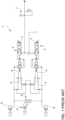
- FIG. 1 generically discloses a hydraulic arrangement according to the present invention and configured to control the actuation of rear brakes 2a, 2b of a work vehicle, not shown.
- the hydraulic arrangement 1 is configured to control a rear left brake 2a and a rear right brake 2b of the work vehicle.
- Hydraulic arrangement 1 comprises a master brake cylinder module 3 comprising a master brake cylinder 4a, 4b for each of the rear brake 2a, 2b and a respective actuation valve 5a, 5b for each of such master brake cylinders 4a, 4b.
- the disclosed exemplarily master brake cylinder module 3 comprises the same elements for left rear brake 2a and right rear brake 2b, only the elements for operating the left rear brake 2a will be described, assuming the index "a" together the reference number. The same elements with index "b" are present for operating the right rear brake 2b.
- the master brake cylinder 4a comprises a housing 6a and a piston 7a configured to slide inside the housing 6a that is further configured to house fluid in pressure.
- the housing 6a is fluidly connected via a conduit 8a to the left rear brake 2a. Indeed a motion of the piston 7a inside the housing 6a tends to push away through conduit 8a the fluid in pressure thereby activating the left rear brake 2a.
- hydraulic arrangement 1 further comprises a source 10 of fluid in pressure fluidly connected to valve 5a.
- the source 10 comprises a single accumulator 11 but it's clear that the source may be separated for each left and right rear brake 2a, 2b or may be provided with a different and more complex hydraulic arrangement.
- the source 10 is fluidly connected to a first port 5a' of actuation valve 5a via a conduit 15; indeed it's separated then into two branches 15a, 15b to be connected to each actuation valve 5a, 5b.
- a second port 5a " actuation valve 5a is fluidly connected via a conduit 16a to allow a hydraulic signal to exert a hydraulic pressure, in parallel to mechanical pedal 9a.
- Such hydraulic signal is selectively connected by connecting the second port 5a " to the first port 5a' of actuation valve 5a, as described below.
- the hydraulic signal can vary from zero in a first position of the actuation valve 5a to a maximum value in a further position of the actuation valve 5a proportionally at the pedal load applied.
- second port 5a'' i.e. conduit 16a
- conduit 16a may further be fluidly connected to output conduit 8a of housing 6a of master bake cylinder 4a via a related conduit 17a.
- the hydraulic arrangement 1 comprises an intermediate valve 18a rigidly carried by actuation valve 5a configured to allow the passage of fluid between the actuation valve 5a and the housing 16a in both directions or to allow the passage of such fluid in only one direction, e.g. from actuation valve 5a to housing 16.
- the conduit 17a comprises a central portion into which is divided into two branches and the intermediate valve 18a is fluidly interposed between such branches. Accordingly, such intermediate valve 18a is a two-position four ways valve.
- actuation valve 5a further defines a third port 5a′′′ fluidly connected to discharge 19.
- actuation valve 5a is a three ways proportional valve.
- actuation valve 5a can assume at least a first position into which the second port 5a " is connected to its third port 5a′′′ and a second position into which the second port 5a " is fluidly connected to the first port 5a'.
- hydraulic arrangement 1 further comprises pressure balancing means 20 fluidly interposed between the housings 6a of the master cylinders 4a, 4b and here not described in detail for sake of brevity.
- conduits 17a, 17b are isolated and second port 5a " , 5b " is sent to shuttle valve 21.
- both hydraulic signals come from the left or right sides of the master cylinder module 3, then a common hydraulic signal is sent to the front brakes 22, thereby activating these latter. Such activation may be more or less delayed in function of the brake design.
- the proposed hydraulic arrangement 1 can be used for different typologies of vehicle already comprising booster master brake cylinder modules for controlling rear brakes with minimal modifications.
- front brakes 22 to rear brakes 2a, 2b does not modify the pedal stroke needed to activate rear brakes 2a, 2b.
Landscapes
- Engineering & Computer Science (AREA)
- Transportation (AREA)
- Mechanical Engineering (AREA)
- Braking Systems And Boosters (AREA)
- Transmission Of Braking Force In Braking Systems (AREA)
Claims (5)
- Hydraulische Anordnung (1) zum Steuern vorderer und hinterer Bremsen (22; 2a, 2b) eines Nutzfahrzeugs mit einem Hauptbremszylindermodul (3) und einer Quelle (10; 12) von mit Druck beaufschlagtem Fluid, wobei das Hauptbremszylindermodul (3) umfasst:- einen rechten und einen linken Hauptzylinder (4a, 4b),- wobei mindestens ein Hauptzylinder (4a, 4b) mit den hinteren Bremsen (2a, 2b) fluidisch verbunden ist;- ein Betätigungsventil (5a, 5b) für jeden aus rechtem und linkem Hauptzylinder (4a, 4b), wobei das Betätigungsventil (5a, 5b) den Fluidfluss steuert, der von dem rechten und linken Hauptzylinder (4a, 4b) zu den Bremsen (2a, 2b) in Abhängigkeit von einer Kraft geleitet wird, die auf ein Pedal (9a, 9b) wirkt;wobei jedes Betätigungsventil (5a, 5b) einen ersten Anschluss (5a', 5b'), einen zweiten Anschluss (5a", 5b") und einen dritten Anschluss (5a‴, 5b‴) umfasst,wobei der erste Anschluss mit der Quelle (10; 12) fluidisch verbunden ist,wobei der zweite Anschluss (5a", 5b") mit dem Betätigungsventil (5a, 5b) fluidisch verbunden ist, um zusätzlich zu der Kraft, die auf das Pedal (9a, 9b) wirkt, einen Druck auf das Betätigungsventil (5a, 5b) auszuüben,wobei der dritte Anschluss (5a‴, 5b‴) mit einem Auslass (19) fluidisch verbunden ist,wobei jedes Betätigungsventil (5a, 5b) dazu eingerichtet ist, zwischen einer ersten Position, in der der erste Anschluss (5a', 5b') mit dem dritten Anschluss (5a‴, 5b‴) fluidisch verbunden ist und der zweite Anschluss (5a", 5b") geschlossen ist, und einer zweiten Position, in der der erste Anschluss (5a', 5b') mit dem zweiten Anschluss (5a", 5b") verbunden ist und der dritte Anschluss (5a‴, 5b‴) geschlossen ist, zu wechseln,wobei die hydraulische Anordnung (1) des Weiteren ein "UND"-Ventil (21) umfasst, das zwischen den zweiten Anschlüssen (5a", 5b") der Betätigungsventile (5a, 5b) und den vorderen Bremsen (22) angeordnet ist.
- Hydraulische Anordnung nach Anspruch 1, wobei das "UND"-Ventil (21) ein Wechselventil ist.
- Hydraulische Anordnung nach Anspruch 1 oder 2, des Weiteren umfassend ein mittleres Ventil (18a, 18b) für jedes Betätigungsventil (5a, 5b), das zwischen Leitungen (16a, 16b), die den zweiten Anschluss (5a", 5b") mit dem Betätigungsventil (5a, 5b) fluidisch verbinden, und Leitungen (8a, 8b), die jeweils einen der Hauptzylinder (4a, 4b) mit den Bremsen (2a, 2b) fluidisch verbinden, fluidisch angeordnet ist,
wobei das mittlere Ventil (18a, 18b) dazu eingerichtet ist, den Durchgang von Fluid in beide Richtungen zwischen den Leitungen (8a, 8b; 16a, 16b) zu ermöglichen oder den Durchgang von Fluid nur von dem Betätigungsventil (5a, 5b) zu den hinteren Bremsen (2a, 2b) zu ermöglichen. - Hydraulische Anordnung nach Anspruch 1 oder 2, wobei der rechte Hauptzylinder (4a) und linke Hauptzylinder (4b) mittels einer entsprechenden Leitung (8a, 8b) mit einer entsprechenden hinteren Bremse (2a, 2b) fluidisch verbunden sind.
- Nutzfahrzeug mit hinteren Bremsen (2a, 2b) und vorderen Bremsen (22) zum Bremsen des Nutzfahrzeugs, einer Quelle (12) von mit Druck beaufschlagtem Fluid und einer hydraulischen Anordnung (1) nach einem der vorhergehenden Ansprüche zum Steuern der vorderen und hinteren Bremsen (22; 2a, 2b).
Applications Claiming Priority (2)
| Application Number | Priority Date | Filing Date | Title |
|---|---|---|---|
| IT102020000012430A IT202000012430A1 (it) | 2020-05-26 | 2020-05-26 | Disposizione idraulica migliorata di controllo di un servofreno per veicoli da lavoro |
| PCT/EP2021/063981 WO2021239779A1 (en) | 2020-05-26 | 2021-05-26 | Improved boosted brake control hydraulic arrangement for work vehicles |
Publications (2)
| Publication Number | Publication Date |
|---|---|
| EP4157685A1 EP4157685A1 (de) | 2023-04-05 |
| EP4157685B1 true EP4157685B1 (de) | 2024-07-10 |
Family
ID=71994991
Family Applications (1)
| Application Number | Title | Priority Date | Filing Date |
|---|---|---|---|
| EP21726688.1A Active EP4157685B1 (de) | 2020-05-26 | 2021-05-26 | Verbesserte verstärkte bremssteuereinrichtung für arbeitsfahrzeuge |
Country Status (3)
| Country | Link |
|---|---|
| EP (1) | EP4157685B1 (de) |
| IT (1) | IT202000012430A1 (de) |
| WO (1) | WO2021239779A1 (de) |
Families Citing this family (1)
| Publication number | Priority date | Publication date | Assignee | Title |
|---|---|---|---|---|
| EP4448354A1 (de) * | 2021-12-17 | 2024-10-23 | ZF Off-Highway Solutions Minnesota Inc. | Vollkraftbremsventil mit bremsdruckversatz |
Family Cites Families (5)
| Publication number | Priority date | Publication date | Assignee | Title |
|---|---|---|---|---|
| ATE487648T1 (de) * | 2006-06-28 | 2010-11-15 | Studio Tecnico 6M Srl | Betriebsvorrichtung |
| US10556575B2 (en) * | 2015-03-04 | 2020-02-11 | Agco International Gmbh | Braking system |
| IT201800006929A1 (it) * | 2018-07-04 | 2020-01-04 | Disposizione idraulica di frenata per veicoli da fuori strada | |
| IT201800007831A1 (it) * | 2018-08-03 | 2020-02-03 | Cnh Ind Italia Spa | Valvola di potenza per freni |
| US20200047738A1 (en) * | 2018-08-13 | 2020-02-13 | Cnh Industrial America Llc | System and method for providing brake-assisted steering to a work vehicle based on work vehicle wheel speeds |
-
2020
- 2020-05-26 IT IT102020000012430A patent/IT202000012430A1/it unknown
-
2021
- 2021-05-26 WO PCT/EP2021/063981 patent/WO2021239779A1/en not_active Ceased
- 2021-05-26 EP EP21726688.1A patent/EP4157685B1/de active Active
Also Published As
| Publication number | Publication date |
|---|---|
| EP4157685A1 (de) | 2023-04-05 |
| IT202000012430A1 (it) | 2021-11-26 |
| WO2021239779A1 (en) | 2021-12-02 |
Similar Documents
| Publication | Publication Date | Title |
|---|---|---|
| CN102971192B (zh) | 用于车辆制动系统的液压组件 | |
| US4449369A (en) | Power assisted hydraulic control system | |
| US11945419B2 (en) | Brake system and motor vehicle | |
| US11964644B2 (en) | Method for operating a brake system, and brake system | |
| GB2170286A (en) | Brake system with slip control | |
| KR20160088382A (ko) | 모터 차량용 브레이크 시스템 | |
| US20120326492A1 (en) | Brake system having a pressure modulation cylinder | |
| EP4157685B1 (de) | Verbesserte verstärkte bremssteuereinrichtung für arbeitsfahrzeuge | |
| JPH02258458A (ja) | ブレーキ装置 | |
| GB1183825A (en) | Improvements in or relating to Hydraulic Systems. | |
| CN116080611A (zh) | 用于车辆的制动系统 | |
| JPS6366702B2 (de) | ||
| US10132057B2 (en) | Traveling working machine | |
| EP4172010B1 (de) | Verbesserte hydraulische anordnung für die steuerung eines bremskraftverstärkers für arbeitsfahrzeuge | |
| JPH0637162B2 (ja) | 自動車の制動力制御装置 | |
| GB2128279A (en) | Hydraulic brake master cylinder and booster arrangement | |
| CN108016420A (zh) | 电子线控制动系统的主缸结构 | |
| GB2160607A (en) | A vehicular hydraulic brake system | |
| CN101743155B (zh) | 液压式车辆制动系统和运行液压式车辆制动系统的方法 | |
| US5005918A (en) | Automotive vehicle brake system | |
| JPH031183B2 (de) | ||
| US4076323A (en) | Fluid brake system for a vehicle | |
| GB2084276A (en) | Brake force booster | |
| CN114454856A (zh) | 电动液压制动系统 | |
| CN116409298B (zh) | 电子液压制动系统及其运行方法和机动车 |
Legal Events
| Date | Code | Title | Description |
|---|---|---|---|
| STAA | Information on the status of an ep patent application or granted ep patent |
Free format text: STATUS: UNKNOWN |
|
| STAA | Information on the status of an ep patent application or granted ep patent |
Free format text: STATUS: THE INTERNATIONAL PUBLICATION HAS BEEN MADE |
|
| PUAI | Public reference made under article 153(3) epc to a published international application that has entered the european phase |
Free format text: ORIGINAL CODE: 0009012 |
|
| STAA | Information on the status of an ep patent application or granted ep patent |
Free format text: STATUS: REQUEST FOR EXAMINATION WAS MADE |
|
| 17P | Request for examination filed |
Effective date: 20230102 |
|
| AK | Designated contracting states |
Kind code of ref document: A1 Designated state(s): AL AT BE BG CH CY CZ DE DK EE ES FI FR GB GR HR HU IE IS IT LI LT LU LV MC MK MT NL NO PL PT RO RS SE SI SK SM TR |
|
| DAV | Request for validation of the european patent (deleted) | ||
| DAX | Request for extension of the european patent (deleted) | ||
| GRAP | Despatch of communication of intention to grant a patent |
Free format text: ORIGINAL CODE: EPIDOSNIGR1 |
|
| STAA | Information on the status of an ep patent application or granted ep patent |
Free format text: STATUS: GRANT OF PATENT IS INTENDED |
|
| INTG | Intention to grant announced |
Effective date: 20231221 |
|
| GRAS | Grant fee paid |
Free format text: ORIGINAL CODE: EPIDOSNIGR3 |
|
| GRAA | (expected) grant |
Free format text: ORIGINAL CODE: 0009210 |
|
| STAA | Information on the status of an ep patent application or granted ep patent |
Free format text: STATUS: THE PATENT HAS BEEN GRANTED |
|
| AK | Designated contracting states |
Kind code of ref document: B1 Designated state(s): AL AT BE BG CH CY CZ DE DK EE ES FI FR GB GR HR HU IE IS IT LI LT LU LV MC MK MT NL NO PL PT RO RS SE SI SK SM TR |
|
| REG | Reference to a national code |
Ref country code: CH Ref legal event code: EP |
|
| REG | Reference to a national code |
Ref country code: DE Ref legal event code: R096 Ref document number: 602021015508 Country of ref document: DE |
|
| REG | Reference to a national code |
Ref country code: LT Ref legal event code: MG9D |
|
| REG | Reference to a national code |
Ref country code: NL Ref legal event code: MP Effective date: 20240710 |
|
| PG25 | Lapsed in a contracting state [announced via postgrant information from national office to epo] |
Ref country code: PT Free format text: LAPSE BECAUSE OF FAILURE TO SUBMIT A TRANSLATION OF THE DESCRIPTION OR TO PAY THE FEE WITHIN THE PRESCRIBED TIME-LIMIT Effective date: 20241111 |
|
| REG | Reference to a national code |
Ref country code: AT Ref legal event code: MK05 Ref document number: 1701803 Country of ref document: AT Kind code of ref document: T Effective date: 20240710 |
|
| PG25 | Lapsed in a contracting state [announced via postgrant information from national office to epo] |
Ref country code: NL Free format text: LAPSE BECAUSE OF FAILURE TO SUBMIT A TRANSLATION OF THE DESCRIPTION OR TO PAY THE FEE WITHIN THE PRESCRIBED TIME-LIMIT Effective date: 20240710 |
|
| PG25 | Lapsed in a contracting state [announced via postgrant information from national office to epo] |
Ref country code: PT Free format text: LAPSE BECAUSE OF FAILURE TO SUBMIT A TRANSLATION OF THE DESCRIPTION OR TO PAY THE FEE WITHIN THE PRESCRIBED TIME-LIMIT Effective date: 20241111 Ref country code: NL Free format text: LAPSE BECAUSE OF FAILURE TO SUBMIT A TRANSLATION OF THE DESCRIPTION OR TO PAY THE FEE WITHIN THE PRESCRIBED TIME-LIMIT Effective date: 20240710 |
|
| PG25 | Lapsed in a contracting state [announced via postgrant information from national office to epo] |
Ref country code: NO Free format text: LAPSE BECAUSE OF FAILURE TO SUBMIT A TRANSLATION OF THE DESCRIPTION OR TO PAY THE FEE WITHIN THE PRESCRIBED TIME-LIMIT Effective date: 20241010 |
|
| PG25 | Lapsed in a contracting state [announced via postgrant information from national office to epo] |
Ref country code: FI Free format text: LAPSE BECAUSE OF FAILURE TO SUBMIT A TRANSLATION OF THE DESCRIPTION OR TO PAY THE FEE WITHIN THE PRESCRIBED TIME-LIMIT Effective date: 20240710 Ref country code: GR Free format text: LAPSE BECAUSE OF FAILURE TO SUBMIT A TRANSLATION OF THE DESCRIPTION OR TO PAY THE FEE WITHIN THE PRESCRIBED TIME-LIMIT Effective date: 20241011 Ref country code: PL Free format text: LAPSE BECAUSE OF FAILURE TO SUBMIT A TRANSLATION OF THE DESCRIPTION OR TO PAY THE FEE WITHIN THE PRESCRIBED TIME-LIMIT Effective date: 20240710 |
|
| PG25 | Lapsed in a contracting state [announced via postgrant information from national office to epo] |
Ref country code: BG Free format text: LAPSE BECAUSE OF FAILURE TO SUBMIT A TRANSLATION OF THE DESCRIPTION OR TO PAY THE FEE WITHIN THE PRESCRIBED TIME-LIMIT Effective date: 20240710 |
|
| PG25 | Lapsed in a contracting state [announced via postgrant information from national office to epo] |
Ref country code: LV Free format text: LAPSE BECAUSE OF FAILURE TO SUBMIT A TRANSLATION OF THE DESCRIPTION OR TO PAY THE FEE WITHIN THE PRESCRIBED TIME-LIMIT Effective date: 20240710 |
|
| PG25 | Lapsed in a contracting state [announced via postgrant information from national office to epo] |
Ref country code: AT Free format text: LAPSE BECAUSE OF FAILURE TO SUBMIT A TRANSLATION OF THE DESCRIPTION OR TO PAY THE FEE WITHIN THE PRESCRIBED TIME-LIMIT Effective date: 20240710 Ref country code: IS Free format text: LAPSE BECAUSE OF FAILURE TO SUBMIT A TRANSLATION OF THE DESCRIPTION OR TO PAY THE FEE WITHIN THE PRESCRIBED TIME-LIMIT Effective date: 20241110 |
|
| PG25 | Lapsed in a contracting state [announced via postgrant information from national office to epo] |
Ref country code: HR Free format text: LAPSE BECAUSE OF FAILURE TO SUBMIT A TRANSLATION OF THE DESCRIPTION OR TO PAY THE FEE WITHIN THE PRESCRIBED TIME-LIMIT Effective date: 20240710 |
|
| PG25 | Lapsed in a contracting state [announced via postgrant information from national office to epo] |
Ref country code: RS Free format text: LAPSE BECAUSE OF FAILURE TO SUBMIT A TRANSLATION OF THE DESCRIPTION OR TO PAY THE FEE WITHIN THE PRESCRIBED TIME-LIMIT Effective date: 20241010 Ref country code: ES Free format text: LAPSE BECAUSE OF FAILURE TO SUBMIT A TRANSLATION OF THE DESCRIPTION OR TO PAY THE FEE WITHIN THE PRESCRIBED TIME-LIMIT Effective date: 20240710 |
|
| PG25 | Lapsed in a contracting state [announced via postgrant information from national office to epo] |
Ref country code: RS Free format text: LAPSE BECAUSE OF FAILURE TO SUBMIT A TRANSLATION OF THE DESCRIPTION OR TO PAY THE FEE WITHIN THE PRESCRIBED TIME-LIMIT Effective date: 20241010 Ref country code: PL Free format text: LAPSE BECAUSE OF FAILURE TO SUBMIT A TRANSLATION OF THE DESCRIPTION OR TO PAY THE FEE WITHIN THE PRESCRIBED TIME-LIMIT Effective date: 20240710 Ref country code: NO Free format text: LAPSE BECAUSE OF FAILURE TO SUBMIT A TRANSLATION OF THE DESCRIPTION OR TO PAY THE FEE WITHIN THE PRESCRIBED TIME-LIMIT Effective date: 20241010 Ref country code: LV Free format text: LAPSE BECAUSE OF FAILURE TO SUBMIT A TRANSLATION OF THE DESCRIPTION OR TO PAY THE FEE WITHIN THE PRESCRIBED TIME-LIMIT Effective date: 20240710 Ref country code: IS Free format text: LAPSE BECAUSE OF FAILURE TO SUBMIT A TRANSLATION OF THE DESCRIPTION OR TO PAY THE FEE WITHIN THE PRESCRIBED TIME-LIMIT Effective date: 20241110 Ref country code: HR Free format text: LAPSE BECAUSE OF FAILURE TO SUBMIT A TRANSLATION OF THE DESCRIPTION OR TO PAY THE FEE WITHIN THE PRESCRIBED TIME-LIMIT Effective date: 20240710 Ref country code: GR Free format text: LAPSE BECAUSE OF FAILURE TO SUBMIT A TRANSLATION OF THE DESCRIPTION OR TO PAY THE FEE WITHIN THE PRESCRIBED TIME-LIMIT Effective date: 20241011 Ref country code: FI Free format text: LAPSE BECAUSE OF FAILURE TO SUBMIT A TRANSLATION OF THE DESCRIPTION OR TO PAY THE FEE WITHIN THE PRESCRIBED TIME-LIMIT Effective date: 20240710 Ref country code: ES Free format text: LAPSE BECAUSE OF FAILURE TO SUBMIT A TRANSLATION OF THE DESCRIPTION OR TO PAY THE FEE WITHIN THE PRESCRIBED TIME-LIMIT Effective date: 20240710 Ref country code: BG Free format text: LAPSE BECAUSE OF FAILURE TO SUBMIT A TRANSLATION OF THE DESCRIPTION OR TO PAY THE FEE WITHIN THE PRESCRIBED TIME-LIMIT Effective date: 20240710 Ref country code: AT Free format text: LAPSE BECAUSE OF FAILURE TO SUBMIT A TRANSLATION OF THE DESCRIPTION OR TO PAY THE FEE WITHIN THE PRESCRIBED TIME-LIMIT Effective date: 20240710 |
|
| REG | Reference to a national code |
Ref country code: DE Ref legal event code: R097 Ref document number: 602021015508 Country of ref document: DE |
|
| PG25 | Lapsed in a contracting state [announced via postgrant information from national office to epo] |
Ref country code: DK Free format text: LAPSE BECAUSE OF FAILURE TO SUBMIT A TRANSLATION OF THE DESCRIPTION OR TO PAY THE FEE WITHIN THE PRESCRIBED TIME-LIMIT Effective date: 20240710 Ref country code: SM Free format text: LAPSE BECAUSE OF FAILURE TO SUBMIT A TRANSLATION OF THE DESCRIPTION OR TO PAY THE FEE WITHIN THE PRESCRIBED TIME-LIMIT Effective date: 20240710 Ref country code: RO Free format text: LAPSE BECAUSE OF FAILURE TO SUBMIT A TRANSLATION OF THE DESCRIPTION OR TO PAY THE FEE WITHIN THE PRESCRIBED TIME-LIMIT Effective date: 20240710 |
|
| PG25 | Lapsed in a contracting state [announced via postgrant information from national office to epo] |
Ref country code: EE Free format text: LAPSE BECAUSE OF FAILURE TO SUBMIT A TRANSLATION OF THE DESCRIPTION OR TO PAY THE FEE WITHIN THE PRESCRIBED TIME-LIMIT Effective date: 20240710 |
|
| PG25 | Lapsed in a contracting state [announced via postgrant information from national office to epo] |
Ref country code: CZ Free format text: LAPSE BECAUSE OF FAILURE TO SUBMIT A TRANSLATION OF THE DESCRIPTION OR TO PAY THE FEE WITHIN THE PRESCRIBED TIME-LIMIT Effective date: 20240710 |
|
| PG25 | Lapsed in a contracting state [announced via postgrant information from national office to epo] |
Ref country code: SK Free format text: LAPSE BECAUSE OF FAILURE TO SUBMIT A TRANSLATION OF THE DESCRIPTION OR TO PAY THE FEE WITHIN THE PRESCRIBED TIME-LIMIT Effective date: 20240710 |
|
| PLBE | No opposition filed within time limit |
Free format text: ORIGINAL CODE: 0009261 |
|
| STAA | Information on the status of an ep patent application or granted ep patent |
Free format text: STATUS: NO OPPOSITION FILED WITHIN TIME LIMIT |
|
| 26N | No opposition filed |
Effective date: 20250411 |
|
| PGFP | Annual fee paid to national office [announced via postgrant information from national office to epo] |
Ref country code: DE Payment date: 20250528 Year of fee payment: 5 |
|
| PGFP | Annual fee paid to national office [announced via postgrant information from national office to epo] |
Ref country code: GB Payment date: 20250520 Year of fee payment: 5 |
|
| PGFP | Annual fee paid to national office [announced via postgrant information from national office to epo] |
Ref country code: IT Payment date: 20250522 Year of fee payment: 5 |
|
| PGFP | Annual fee paid to national office [announced via postgrant information from national office to epo] |
Ref country code: FR Payment date: 20250526 Year of fee payment: 5 |
|
| PG25 | Lapsed in a contracting state [announced via postgrant information from national office to epo] |
Ref country code: SE Free format text: LAPSE BECAUSE OF FAILURE TO SUBMIT A TRANSLATION OF THE DESCRIPTION OR TO PAY THE FEE WITHIN THE PRESCRIBED TIME-LIMIT Effective date: 20240710 |
|
| REG | Reference to a national code |
Ref country code: CH Ref legal event code: H13 Free format text: ST27 STATUS EVENT CODE: U-0-0-H10-H13 (AS PROVIDED BY THE NATIONAL OFFICE) Effective date: 20251223 |
|
| PG25 | Lapsed in a contracting state [announced via postgrant information from national office to epo] |
Ref country code: LU Free format text: LAPSE BECAUSE OF NON-PAYMENT OF DUE FEES Effective date: 20250526 |
|
| PG25 | Lapsed in a contracting state [announced via postgrant information from national office to epo] |
Ref country code: CH Free format text: LAPSE BECAUSE OF NON-PAYMENT OF DUE FEES Effective date: 20250531 |
|
| REG | Reference to a national code |
Ref country code: BE Ref legal event code: MM Effective date: 20250531 |
|
| PG25 | Lapsed in a contracting state [announced via postgrant information from national office to epo] |
Ref country code: MC Free format text: LAPSE BECAUSE OF FAILURE TO SUBMIT A TRANSLATION OF THE DESCRIPTION OR TO PAY THE FEE WITHIN THE PRESCRIBED TIME-LIMIT Effective date: 20240710 |