EP4172010B1 - Verbesserte hydraulische anordnung für die steuerung eines bremskraftverstärkers für arbeitsfahrzeuge - Google Patents
Verbesserte hydraulische anordnung für die steuerung eines bremskraftverstärkers für arbeitsfahrzeuge Download PDFInfo
- Publication number
- EP4172010B1 EP4172010B1 EP21726689.9A EP21726689A EP4172010B1 EP 4172010 B1 EP4172010 B1 EP 4172010B1 EP 21726689 A EP21726689 A EP 21726689A EP 4172010 B1 EP4172010 B1 EP 4172010B1
- Authority
- EP
- European Patent Office
- Prior art keywords
- valve
- port
- hydraulic arrangement
- remote control
- actuation
- Prior art date
- Legal status (The legal status is an assumption and is not a legal conclusion. Google has not performed a legal analysis and makes no representation as to the accuracy of the status listed.)
- Active
Links
Images

Classifications
-
- B—PERFORMING OPERATIONS; TRANSPORTING
- B60—VEHICLES IN GENERAL
- B60T—VEHICLE BRAKE CONTROL SYSTEMS OR PARTS THEREOF; BRAKE CONTROL SYSTEMS OR PARTS THEREOF, IN GENERAL; ARRANGEMENT OF BRAKING ELEMENTS ON VEHICLES IN GENERAL; PORTABLE DEVICES FOR PREVENTING UNWANTED MOVEMENT OF VEHICLES; VEHICLE MODIFICATIONS TO FACILITATE COOLING OF BRAKES
- B60T7/00—Brake-action initiating means
- B60T7/02—Brake-action initiating means for personal initiation
- B60T7/04—Brake-action initiating means for personal initiation foot actuated
- B60T7/042—Brake-action initiating means for personal initiation foot actuated by electrical means, e.g. using travel or force sensors
-
- B—PERFORMING OPERATIONS; TRANSPORTING
- B60—VEHICLES IN GENERAL
- B60T—VEHICLE BRAKE CONTROL SYSTEMS OR PARTS THEREOF; BRAKE CONTROL SYSTEMS OR PARTS THEREOF, IN GENERAL; ARRANGEMENT OF BRAKING ELEMENTS ON VEHICLES IN GENERAL; PORTABLE DEVICES FOR PREVENTING UNWANTED MOVEMENT OF VEHICLES; VEHICLE MODIFICATIONS TO FACILITATE COOLING OF BRAKES
- B60T11/00—Transmitting braking action from initiating means to ultimate brake actuator without power assistance or drive or where such assistance or drive is irrelevant
- B60T11/10—Transmitting braking action from initiating means to ultimate brake actuator without power assistance or drive or where such assistance or drive is irrelevant transmitting by fluid means, e.g. hydraulic
- B60T11/16—Master control, e.g. master cylinders
- B60T11/20—Tandem, side-by-side, or other multiple master cylinder units
- B60T11/21—Tandem, side-by-side, or other multiple master cylinder units with two pedals operating on respective circuits, pressures therein being equalised when both pedals are operated together, e.g. for steering
-
- B—PERFORMING OPERATIONS; TRANSPORTING
- B60—VEHICLES IN GENERAL
- B60T—VEHICLE BRAKE CONTROL SYSTEMS OR PARTS THEREOF; BRAKE CONTROL SYSTEMS OR PARTS THEREOF, IN GENERAL; ARRANGEMENT OF BRAKING ELEMENTS ON VEHICLES IN GENERAL; PORTABLE DEVICES FOR PREVENTING UNWANTED MOVEMENT OF VEHICLES; VEHICLE MODIFICATIONS TO FACILITATE COOLING OF BRAKES
- B60T11/00—Transmitting braking action from initiating means to ultimate brake actuator without power assistance or drive or where such assistance or drive is irrelevant
- B60T11/10—Transmitting braking action from initiating means to ultimate brake actuator without power assistance or drive or where such assistance or drive is irrelevant transmitting by fluid means, e.g. hydraulic
- B60T11/16—Master control, e.g. master cylinders
- B60T11/22—Master control, e.g. master cylinders characterised by being integral with reservoir
-
- B—PERFORMING OPERATIONS; TRANSPORTING
- B60—VEHICLES IN GENERAL
- B60T—VEHICLE BRAKE CONTROL SYSTEMS OR PARTS THEREOF; BRAKE CONTROL SYSTEMS OR PARTS THEREOF, IN GENERAL; ARRANGEMENT OF BRAKING ELEMENTS ON VEHICLES IN GENERAL; PORTABLE DEVICES FOR PREVENTING UNWANTED MOVEMENT OF VEHICLES; VEHICLE MODIFICATIONS TO FACILITATE COOLING OF BRAKES
- B60T13/00—Transmitting braking action from initiating means to ultimate brake actuator with power assistance or drive; Brake systems incorporating such transmitting means, e.g. air-pressure brake systems
- B60T13/10—Transmitting braking action from initiating means to ultimate brake actuator with power assistance or drive; Brake systems incorporating such transmitting means, e.g. air-pressure brake systems with fluid assistance, drive, or release
- B60T13/12—Transmitting braking action from initiating means to ultimate brake actuator with power assistance or drive; Brake systems incorporating such transmitting means, e.g. air-pressure brake systems with fluid assistance, drive, or release the fluid being liquid
- B60T13/14—Transmitting braking action from initiating means to ultimate brake actuator with power assistance or drive; Brake systems incorporating such transmitting means, e.g. air-pressure brake systems with fluid assistance, drive, or release the fluid being liquid using accumulators or reservoirs fed by pumps
- B60T13/141—Systems with distributor valve
-
- B—PERFORMING OPERATIONS; TRANSPORTING
- B60—VEHICLES IN GENERAL
- B60T—VEHICLE BRAKE CONTROL SYSTEMS OR PARTS THEREOF; BRAKE CONTROL SYSTEMS OR PARTS THEREOF, IN GENERAL; ARRANGEMENT OF BRAKING ELEMENTS ON VEHICLES IN GENERAL; PORTABLE DEVICES FOR PREVENTING UNWANTED MOVEMENT OF VEHICLES; VEHICLE MODIFICATIONS TO FACILITATE COOLING OF BRAKES
- B60T13/00—Transmitting braking action from initiating means to ultimate brake actuator with power assistance or drive; Brake systems incorporating such transmitting means, e.g. air-pressure brake systems
- B60T13/10—Transmitting braking action from initiating means to ultimate brake actuator with power assistance or drive; Brake systems incorporating such transmitting means, e.g. air-pressure brake systems with fluid assistance, drive, or release
- B60T13/12—Transmitting braking action from initiating means to ultimate brake actuator with power assistance or drive; Brake systems incorporating such transmitting means, e.g. air-pressure brake systems with fluid assistance, drive, or release the fluid being liquid
- B60T13/14—Transmitting braking action from initiating means to ultimate brake actuator with power assistance or drive; Brake systems incorporating such transmitting means, e.g. air-pressure brake systems with fluid assistance, drive, or release the fluid being liquid using accumulators or reservoirs fed by pumps
- B60T13/142—Systems with master cylinder
- B60T13/143—Master cylinder mechanically coupled with booster
- B60T13/144—Pilot valve provided inside booster piston
-
- B—PERFORMING OPERATIONS; TRANSPORTING
- B60—VEHICLES IN GENERAL
- B60T—VEHICLE BRAKE CONTROL SYSTEMS OR PARTS THEREOF; BRAKE CONTROL SYSTEMS OR PARTS THEREOF, IN GENERAL; ARRANGEMENT OF BRAKING ELEMENTS ON VEHICLES IN GENERAL; PORTABLE DEVICES FOR PREVENTING UNWANTED MOVEMENT OF VEHICLES; VEHICLE MODIFICATIONS TO FACILITATE COOLING OF BRAKES
- B60T13/00—Transmitting braking action from initiating means to ultimate brake actuator with power assistance or drive; Brake systems incorporating such transmitting means, e.g. air-pressure brake systems
- B60T13/10—Transmitting braking action from initiating means to ultimate brake actuator with power assistance or drive; Brake systems incorporating such transmitting means, e.g. air-pressure brake systems with fluid assistance, drive, or release
- B60T13/12—Transmitting braking action from initiating means to ultimate brake actuator with power assistance or drive; Brake systems incorporating such transmitting means, e.g. air-pressure brake systems with fluid assistance, drive, or release the fluid being liquid
- B60T13/14—Transmitting braking action from initiating means to ultimate brake actuator with power assistance or drive; Brake systems incorporating such transmitting means, e.g. air-pressure brake systems with fluid assistance, drive, or release the fluid being liquid using accumulators or reservoirs fed by pumps
- B60T13/142—Systems with master cylinder
- B60T13/145—Master cylinder integrated or hydraulically coupled with booster
- B60T13/146—Part of the system directly actuated by booster pressure
-
- B—PERFORMING OPERATIONS; TRANSPORTING
- B60—VEHICLES IN GENERAL
- B60T—VEHICLE BRAKE CONTROL SYSTEMS OR PARTS THEREOF; BRAKE CONTROL SYSTEMS OR PARTS THEREOF, IN GENERAL; ARRANGEMENT OF BRAKING ELEMENTS ON VEHICLES IN GENERAL; PORTABLE DEVICES FOR PREVENTING UNWANTED MOVEMENT OF VEHICLES; VEHICLE MODIFICATIONS TO FACILITATE COOLING OF BRAKES
- B60T13/00—Transmitting braking action from initiating means to ultimate brake actuator with power assistance or drive; Brake systems incorporating such transmitting means, e.g. air-pressure brake systems
- B60T13/10—Transmitting braking action from initiating means to ultimate brake actuator with power assistance or drive; Brake systems incorporating such transmitting means, e.g. air-pressure brake systems with fluid assistance, drive, or release
- B60T13/12—Transmitting braking action from initiating means to ultimate brake actuator with power assistance or drive; Brake systems incorporating such transmitting means, e.g. air-pressure brake systems with fluid assistance, drive, or release the fluid being liquid
- B60T13/14—Transmitting braking action from initiating means to ultimate brake actuator with power assistance or drive; Brake systems incorporating such transmitting means, e.g. air-pressure brake systems with fluid assistance, drive, or release the fluid being liquid using accumulators or reservoirs fed by pumps
- B60T13/142—Systems with master cylinder
- B60T13/147—In combination with distributor valve
-
- B—PERFORMING OPERATIONS; TRANSPORTING
- B60—VEHICLES IN GENERAL
- B60T—VEHICLE BRAKE CONTROL SYSTEMS OR PARTS THEREOF; BRAKE CONTROL SYSTEMS OR PARTS THEREOF, IN GENERAL; ARRANGEMENT OF BRAKING ELEMENTS ON VEHICLES IN GENERAL; PORTABLE DEVICES FOR PREVENTING UNWANTED MOVEMENT OF VEHICLES; VEHICLE MODIFICATIONS TO FACILITATE COOLING OF BRAKES
- B60T13/00—Transmitting braking action from initiating means to ultimate brake actuator with power assistance or drive; Brake systems incorporating such transmitting means, e.g. air-pressure brake systems
- B60T13/10—Transmitting braking action from initiating means to ultimate brake actuator with power assistance or drive; Brake systems incorporating such transmitting means, e.g. air-pressure brake systems with fluid assistance, drive, or release
- B60T13/12—Transmitting braking action from initiating means to ultimate brake actuator with power assistance or drive; Brake systems incorporating such transmitting means, e.g. air-pressure brake systems with fluid assistance, drive, or release the fluid being liquid
- B60T13/14—Transmitting braking action from initiating means to ultimate brake actuator with power assistance or drive; Brake systems incorporating such transmitting means, e.g. air-pressure brake systems with fluid assistance, drive, or release the fluid being liquid using accumulators or reservoirs fed by pumps
- B60T13/148—Arrangements for pressure supply
-
- B—PERFORMING OPERATIONS; TRANSPORTING
- B60—VEHICLES IN GENERAL
- B60T—VEHICLE BRAKE CONTROL SYSTEMS OR PARTS THEREOF; BRAKE CONTROL SYSTEMS OR PARTS THEREOF, IN GENERAL; ARRANGEMENT OF BRAKING ELEMENTS ON VEHICLES IN GENERAL; PORTABLE DEVICES FOR PREVENTING UNWANTED MOVEMENT OF VEHICLES; VEHICLE MODIFICATIONS TO FACILITATE COOLING OF BRAKES
- B60T13/00—Transmitting braking action from initiating means to ultimate brake actuator with power assistance or drive; Brake systems incorporating such transmitting means, e.g. air-pressure brake systems
- B60T13/10—Transmitting braking action from initiating means to ultimate brake actuator with power assistance or drive; Brake systems incorporating such transmitting means, e.g. air-pressure brake systems with fluid assistance, drive, or release
- B60T13/66—Electrical control in fluid-pressure brake systems
- B60T13/662—Electrical control in fluid-pressure brake systems characterised by specified functions of the control system components
-
- B—PERFORMING OPERATIONS; TRANSPORTING
- B60—VEHICLES IN GENERAL
- B60T—VEHICLE BRAKE CONTROL SYSTEMS OR PARTS THEREOF; BRAKE CONTROL SYSTEMS OR PARTS THEREOF, IN GENERAL; ARRANGEMENT OF BRAKING ELEMENTS ON VEHICLES IN GENERAL; PORTABLE DEVICES FOR PREVENTING UNWANTED MOVEMENT OF VEHICLES; VEHICLE MODIFICATIONS TO FACILITATE COOLING OF BRAKES
- B60T13/00—Transmitting braking action from initiating means to ultimate brake actuator with power assistance or drive; Brake systems incorporating such transmitting means, e.g. air-pressure brake systems
- B60T13/74—Transmitting braking action from initiating means to ultimate brake actuator with power assistance or drive; Brake systems incorporating such transmitting means, e.g. air-pressure brake systems with electrical assistance or drive
-
- B—PERFORMING OPERATIONS; TRANSPORTING
- B60—VEHICLES IN GENERAL
- B60T—VEHICLE BRAKE CONTROL SYSTEMS OR PARTS THEREOF; BRAKE CONTROL SYSTEMS OR PARTS THEREOF, IN GENERAL; ARRANGEMENT OF BRAKING ELEMENTS ON VEHICLES IN GENERAL; PORTABLE DEVICES FOR PREVENTING UNWANTED MOVEMENT OF VEHICLES; VEHICLE MODIFICATIONS TO FACILITATE COOLING OF BRAKES
- B60T15/00—Construction arrangement, or operation of valves incorporated in power brake systems and not covered by groups B60T11/00 or B60T13/00
- B60T15/02—Application and release valves
- B60T15/04—Driver's valves
- B60T15/043—Driver's valves controlling service pressure brakes
- B60T15/045—Driver's valves controlling service pressure brakes in multiple circuit systems, e.g. dual circuit systems
- B60T15/046—Driver's valves controlling service pressure brakes in multiple circuit systems, e.g. dual circuit systems with valves mounted in tandem
-
- B—PERFORMING OPERATIONS; TRANSPORTING
- B60—VEHICLES IN GENERAL
- B60T—VEHICLE BRAKE CONTROL SYSTEMS OR PARTS THEREOF; BRAKE CONTROL SYSTEMS OR PARTS THEREOF, IN GENERAL; ARRANGEMENT OF BRAKING ELEMENTS ON VEHICLES IN GENERAL; PORTABLE DEVICES FOR PREVENTING UNWANTED MOVEMENT OF VEHICLES; VEHICLE MODIFICATIONS TO FACILITATE COOLING OF BRAKES
- B60T7/00—Brake-action initiating means
- B60T7/12—Brake-action initiating means for automatic initiation; for initiation not subject to will of driver or passenger
- B60T7/16—Brake-action initiating means for automatic initiation; for initiation not subject to will of driver or passenger operated by remote control, i.e. initiating means not mounted on vehicle
-
- B—PERFORMING OPERATIONS; TRANSPORTING
- B60—VEHICLES IN GENERAL
- B60T—VEHICLE BRAKE CONTROL SYSTEMS OR PARTS THEREOF; BRAKE CONTROL SYSTEMS OR PARTS THEREOF, IN GENERAL; ARRANGEMENT OF BRAKING ELEMENTS ON VEHICLES IN GENERAL; PORTABLE DEVICES FOR PREVENTING UNWANTED MOVEMENT OF VEHICLES; VEHICLE MODIFICATIONS TO FACILITATE COOLING OF BRAKES
- B60T2260/00—Interaction of vehicle brake system with other systems
- B60T2260/02—Active Steering, Steer-by-Wire
- B60T2260/022—Rear-wheel steering; Four-wheel steering
Definitions
- the present invention concerns a brake control hydraulic arrangement, in particular a boosted brake control hydraulic arrangement for master brake cylinders of work vehicles, such as agricultural vehicles.
- All vehicles are provided with brakes and, as known, work vehicles such as agricultural vehicles are provided with main brakes on rear wheels of the vehicle that can be actuated hydraulically e.g. thanks to dedicated master brake cylinders.
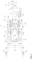
- Figure 1 discloses an exemplarily embodiment of rear brakes control hydraulic arrangement 1' as known in the art.
- such arrangement 1' comprises a brake actuation valve 2' configured to be actuated by a respective pedal 3' by the user of the work vehicle.
- Such brake actuation valve 2' is configured to move a piston 4' making part of a master brake cylinder 5' which consequently push a high pressure fluid into a respective brake 6'.
- the above synthetically defined arrangement is known as boosted master brake cylinder configuration and it is widely used in work vehicle to assist the operator when braking the vehicle.
- work vehicles such as agricultural vehicles are more and more improved to achieve a plurality of autonomous functions such as braking that would be desired to be controlled remotely.
- An aim of the present invention is to satisfy the above mentioned needs in an economic and optimized way.
- FIG. 1 generically discloses a hydraulic arrangement according to the present invention and configured to control the actuation of rear brakes 2a, 2b of a work vehicle, not shown.
- the hydraulic arrangement 1 is configured to control a rear left brake 2a and a rear right brake 2b of the work vehicle.
- Hydraulic arrangement 1 comprises a master brake cylinder module 3 preferably comprising a master brake cylinder 4a, 4b for each of the rear brake 2a, 2b and a respective actuation valve 5a, 5b for each of such master brake cylinders 4a, 4b.
- the disclosed exemplarily master brake cylinder module 3 comprises the same elements for left rear brake 2a and right rear brake 2b, only the elements for operating the left rear brake 2a will be described, assuming the index "a" together the reference number. The same elements with index "b" are present for operating the right rear brake 2b.
- the master brake cylinder 4a comprises a housing 6a and a piston 7a configured to slide inside the housing 6a that is further configured to house fluid in pressure.
- the housing 6a is fluidly connected via a conduit 8a to the left rear brake 2a. Indeed a motion of the piston 7a inside the housing 6a tends to push away through conduit 8a the fluid in pressure thereby activating the left rear brake 2a.
- the piston 7a is mechanically connected to actuation valve 5a so that its motion corresponds to a motion of actuation valve 5a.
- This latter is actuated by a pedal 9a so that the user, by pushing the pedal 9a, can move the actuation valve 5a thereby inserting the piston 7a into the housing 6a.
- hydraulic arrangement 1 further comprises a source 10 of fluid in pressure fluidly connected to valve 5a.
- the source 10 comprises a single accumulator 11 but it's clear that the source may be separated for each left and right rear brake 2a, 2b or may be provided with a different and more complex hydraulic arrangement.
- the accumulator 11 is fluidly connected to a source of fluid in pressure 12 of the work vehicle, e.g. a pump, via a conduit 13 into which it is interposed a check valve 14 to avoid contrary passage of fluid from circuit 1 to the source 12.
- a source of fluid in pressure 12 of the work vehicle e.g. a pump
- the source 10 is fluidly connected to a first port 5a' of actuation valve 5a via a conduit 15; indeed it's separated then into two branches 15a, 15b to be connected to each actuation valve 5a, 5b.
- a second port 5a" actuation valve 5a is fluidly connected via a conduit 16a to allow a hydraulic signal to exert a hydraulic pressure, in parallel to mechanical pedal 9a.
- Such hydraulic signal is selectively connected by connecting the second port 5a" to the first port 5a' of actuation valve 5a, as described below.
- the hydraulic signal can vary from zero in a first position of the actuation valve 5a to a maximum value in a further position of the actuation valve 5a.
- second port 5a'' i.e. conduit 16a
- conduit 16a may further be fluidly connected to output conduit 8a of housing 6a of master bake cylinder 4a via a related conduit 17a.
- the hydraulic arrangement 1 comprises an intermediate valve 18a rigidly carried by actuation valve 5a configured to allow the passage of fluid between the actuation valve 5a and the housing 16a in both directions or to allow the passage of such fluid in only one direction, e.g. from actuation valve 5a to housing 16.
- the conduit 17a comprises a central portion into which is divided into two branches and the intermediate valve 18a is fluidly interposed between such branches. Accordingly, such intermediate valve 18a is a two-position four ways valve.
- actuation valve 5a further defines a third port 5a′′′ fluidly connected to discharge 19.
- actuation valve 5a is a three ways proportional valve.
- actuation valve 5a can assume at least a first position into which the second port 5a'' is connected to its third port 5a''' and a second position into which the second port 5a'' is fluidly connected to the first port 5a'.
- hydraulic arrangement 1 further comprises balancing means 20 fluidly interposed between the housings 6a of the master cylinders 4a, 4b and here not described in detail for sake of brevity.
- the hydraulic arrangement 1 comprises a remote actuation valve 21 fluidly interposed between the source 10 of fluid in pressure, the discharge 19 and each of the actuation valves 5a, 5b.
- the remote actuation valve 21 defines a first port 21' configured to be fluidly connected to third port of actuation valves 5a, 5b, a second port 21", fluidly connected to the source 10 of fluid in pressure and a third port 21′′′ configured to be fluidly connected to discharge 19.
- Valve 21 is configured, in an active condition, to fluidly connect the third ports 5a′′′, 5b′′′ of the actuation valves 5a, 5b to discharge 19 and in a rest condition to fluidly connect these latter to the source 10 of fluid in pressure.
- valve 21 is an electro-actuated valve and, preferably, a proportional three-ways valve.
- a first possible mode of operation can be a standard operation into which valve 21 is activated and therefore allows direct connection of actuation valves 5a, 5b to discharge 19.
- the user of the work vehicle may press the related pedal 9a, 9b thereby starting the compression of piston 7a, 7b into housing 6a, 6b and then the passage of fluid towards brakes 2a, 2b.
- a portion of the fluid from housing is sent to the conduit 16a, 16b to generate the hydraulic signal which exerts a pressure in parallel to the pedal 9a, 9b;furthermore, the passage of fluid from first port 5a′′′, 5b"" to discharge 19 is more and more restricted while the it is fluidly connected to source 10 via conduit 15a, 15b so that also the fluid in pressure coming from conduit 15 strength the hydraulic signal acting in parallel to pedal 9a, 9b.
- the pressure needed on pedal 9a, 9b is lower because the pressure coming from the hydraulic signal in conduit 16a helps the user while pressing pedal 9a, 9b.
- a second possible mode of operation is an electric or a remote mode achieved thanks to valve 21.
- valve 21 during the above described mode of operation is always energized. If de-energized, the valve 21 allows the passage of fluid from source 10 third port 5a′′′, 5b′′′ thereby generating a hydraulic pressure through conduit 16a, 16b to actuation valve 5a, 5b.
- such hydraulic pressure substitutes the initial pedal pressure which is needed to start the boost effect which is further given by the fluid coming from master cylinder 4a, 4b and then from second port 5a'', 5b''', as described above.
- valve 21 is positioned in such limit activated state, the fluid in pressure acts on the third port 5a′′′, 5b′′′ thereby avoiding any connection with the discharge 19 of conduits 16a, 16b and 17a, 17b. In such way, the braking is maintained till it is desired.
- the represented valve 21 is a proportional valve and that the above described operation is a limit one. In normal operation the valve 21 subdivide the flow between the above two described limit conditions.
- valve 21 In order to unbrake the brakes 2a, 2b it is sufficient to energize valve 21 again thereby connecting again third port 5a′′′, 5b′′′ to discharge 19 and, then, allowing actuation valve 5a, 5b to return back to its original position.
- valve 21 In case of malfunctioning of valve 21, e.g. a loss of electrical power on the vehicle, the rest position will restore the braked position, thereby guaranteeing a fail safe activation of the rear brakes 2a, 2b.
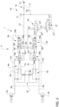
- Figure 3 discloses a second embodiment of the hydraulic arrangement 1 of the present invention that is similar to the embodiment of figure 2 except for the fact that the actuation of remote control valve 21 is different and that they hydraulic arrangement comprising a second remote control valve 22 fluidly interposed between the first remote control valve 21 and the actuation valves 5a, 5b.
- second valve 22 defines a first port 22' configured to be fluidly connected to third port of actuation valves 5a, 5b, a second port 21" fluidly connected to second port of first valve 21 and a third port 21′′′ configured to be fluidly connected to discharge 19.
- First remote control valve 21 is again an electro-actuated valve and, preferably, a proportional three-ways valve but its first port 21' is connected, as said, to second port 22'' of valve 22.
- valve 21 is configured, in active rest condition the first port 21' is connected to second port 22' of second valve 22 to the source 10 of fluid in pressure and in an active condition to fluidly connect second port 22' of second valve 22 to discharge 19.
- Second valve 22 is a bi-stable valve with mechanical detent and preferably an electro-actuated valve. According to the above second valve is a three ways-two positions bi-stable valve. In a first position of second valve 22, the first port 22' if directly connected to its third port 22′′′ while the second port 22" is closed and in a second position of second valve 22, the first port 22' if directly connected to its second port 22' while the third port 22′′′ is closed
- the hydraulic arrangement can be used only by mechanically pressing the pedal 9a, 9b independently by the status of valve 21.
- the hydraulic arrangement can be used in function of the status of valve 21 similarly to the operation described for the first embodiment.
- the first control remote valve 21 it is possible to provide a remote control of the hydraulic arrangement 1 without user intervention while, at the same time, allowing always a on-board user control of the brakes, if needed, thanks to the pedals 9a, 9b.
- remote control given by remote valve 21 may be implemented in a cost-effect way on existing master brake cylinder modules without substantially changes to the piping or to the disposition of the main elements.
- the proposed system is particularly economic, compact and can be implemented on different typologies of hydraulic arrangement.
- the use of the remote valve 21 is intrinsically fail-safe with respect to electrical failures of the work vehicle.
- second remote valve 22 allows to use a rest "non-activated" state of first remote valve 21, thereby reducing the electrical power consumed by this latter.
- a second remote valve 22 in particular a bi-stable valve, allows a clear distinction between manual and remote use and creates a fail-safe and low consumption system for controlling in a versatile way the braking of the work vehicle.
- the second remote control valve 22, as said, is optional.
- the master bake cylinder module 3, the actuation valve 5, the source of fluid in pressure 10, the intermediate valve 18 or the remote control valves 21, 22 can be of any typology suitable to accomplish their operation as claimed.
Landscapes
- Engineering & Computer Science (AREA)
- Transportation (AREA)
- Mechanical Engineering (AREA)
- Braking Systems And Boosters (AREA)
- Valves And Accessory Devices For Braking Systems (AREA)
Claims (10)
- Hydraulikanordnung (1) zum Steuern einer linken und einer rechten hinteren Bremse (2a, 2b) eines Arbeitsfahrzeugs mit einem Hauptbremszylindermodul (3) und einer Quelle (10; 12) von unter Druck stehendem Fluid, wobei das Hauptbremszylindermodul (3) umfasst:- ein Hauptzylindermodul (4a, 4b), das mit den hinteren Bremsen (2a, 2b) verbunden ist;- ein Betätigungsventil (5a, 5b) für jeweils den rechten und den linken Hauptzylinder (4a, 4b), wobei das Betätigungsventil (5a, 5b) den Fluidfluss steuert, der von dem rechten und dem linken Hauptzylinder (4a, 4b) in Abhängigkeit von einer auf ein Pedal (9a, 9b) ausgeübten Kraft zu den Bremsen (2a, 2b) gefördert wird;wobei jedes Betätigungsventil (5a, 5b) einen ersten Anschluss (5a', 5b'), einen zweiten Anschluss (5a", 5b") und einen dritten Anschluss (5a‴, 5b‴) aufweist, wobei der erste Anschluss mit der Quelle (10; 12) fluidisch verbunden ist, der zweite Anschluss (5a", 5b") mit dem Betätigungsventil (5a, 5b) fluidisch verbunden ist, um zusätzlich zu der auf das Pedal (9a, 9b) ausgeübten Kraft einen Druck auf das Betätigungsventil (5a, 5b) auszuüben, und der dritte Anschluss (5a‴, 5b‴) mit einer Ableitung (19) fluidisch verbunden ist,wobei jedes Betätigungsventil (5a, 5b) dazu eingerichtet ist, zwischen einer ersten Position, in der der erste Anschluss (5a', 5b') mit dem dritten Anschluss (5a‴, 5b‴) fluidisch verbunden ist und der zweite Anschluss (5a", 5b") geschlossen ist, und einer zweiten Position, in der der erste Anschluss (5a', 5b') mit dem zweiten Anschluss (5a", 5b") fluidisch verbunden ist und der dritte Anschluss (5a‴, 5b‴) geschlossen ist, überführt zu werden,wobei die Hydraulikanordnung (1) dadurch gekennzeichnet ist, dass sie des Weiteren ein ferngesteuertes Ventil (21) aufweist, das zwischen der Quelle (10; 12), dem dritten Anschluss (5a‴, 5b‴) und der Ableitung (19) fluidisch eingefügt ist und dazu eingerichtet ist, eine erste Position, in der es die fluidische Verbindung zwischen der Quelle (10; 12) und dem dritten Anschluss (5a‴, 5b‴) ermöglicht, und eine zweite Position, in der es die fluidische Verbindung zwischen der Ableitung (19) und dem dritten Anschluss (5a‴, 5b‴) ermöglicht, einzunehmen.
- Hydraulikanordnung nach Anspruch 1, wobei das ferngesteuerte Ventil (21) ein elektrisch betätigtes Ventil ist.
- Hydraulikanordnung nach Anspruch 1 oder 2, wobei das ferngesteuerte Ventil (21) ein Proportionalventil ist.
- Hydraulikanordnung nach einem der vorhergehenden Ansprüche, wobei das ferngesteuerte Ventil (21) elektrisch betätigt sein muss, um die zweite Position aufrechtzuerhalten.
- Hydraulikanordnung nach einem der Ansprüche 1 bis 3, wobei das ferngesteuerte Ventil (21) elektrisch betätigt sein muss, um die erste Position aufrechtzuerhalten, und wobei die Hydraulikanordnung (1) ein weiteres ferngesteuertes Ventil (22) aufweist, das zwischen dem ferngesteuerten Ventil (21), dem dritten Anschluss (5a‴, 5b‴) und der Ableitung (19) fluidisch eingefügt ist und dazu eingerichtet ist, eine erste Position, in der es die fluidische Verbindung zwischen dem ferngesteuerten Ventil (21) und dem dritten Anschluss (5a‴, 5b‴) ermöglicht, und eine zweite Position, in der es die fluidische Verbindung zwischen der Ableitung (19) und dem dritten Anschluss (5a‴, 5b‴) ermöglicht, einzunehmen.
- Hydraulikanordnung nach Anspruch 5, wobei das weitere ferngesteuerte Ventil (22) ein elektrisch betätigtes Ventil ist.
- Hydraulikanordnung nach Anspruch 5 oder 6, wobei das weitere ferngesteuerte Ventil (22) ein bistabiles Ventil ist.
- Hydraulikanordnung nach Anspruch 7, wobei das weitere ferngesteuerte Ventil (22) eine Sperre aufweist.
- Hydraulikanordnung nach einem der vorhergehenden Ansprüche, die des Weiteren ein Zwischenventil (18a, 18b) für jedes Betätigungsventil (5a, 5b) aufweist, das zwischen der Leitung (16a, 16b), die den zweiten Anschluss (5a", 5b") mit dem Betätigungsventil (5a, 5b) fluidisch verbindet, und der Leitung (8a, 8b) fluidisch eingefügt ist, die jeden Hauptzylinder (4a, 4b) mit den Bremsen (2a, 2b) fluidisch verbindet, wobei das Zwischenventil (18a, 18b) dazu eingerichtet ist, den Durchfluss von Fluid zwischen den Leitungen (8a, 8b; 16a, 16b) in beide Richtungen zu erlauben oder den Durchfluss von Fluid nur von dem Betätigungsventil (5a, 5b) in Richtung der hinteren Bremsen (2a, 2b) zu erlauben.
- Arbeitsfahrzeug mit hinteren Bremsen (2a, 2b) zum Bremsen des Arbeitsfahrzeugs, einer Quelle (12) von unter Druck stehendem Fluid und einer Hydraulikanordnung (1) nach einem der vorhergehenden Ansprüche zum Steuern der hinteren Bremsen (2a, 2b).
Applications Claiming Priority (2)
| Application Number | Priority Date | Filing Date | Title |
|---|---|---|---|
| IT102020000012421A IT202000012421A1 (it) | 2020-05-26 | 2020-05-26 | Disposizione idraulica migliorata di controllo di un servofreno per veicoli da lavoro |
| PCT/EP2021/063982 WO2021239780A1 (en) | 2020-05-26 | 2021-05-26 | Improved boosted brake control hydraulic arrangement for work vehicles |
Publications (2)
| Publication Number | Publication Date |
|---|---|
| EP4172010A1 EP4172010A1 (de) | 2023-05-03 |
| EP4172010B1 true EP4172010B1 (de) | 2024-12-18 |
Family
ID=71994990
Family Applications (1)
| Application Number | Title | Priority Date | Filing Date |
|---|---|---|---|
| EP21726689.9A Active EP4172010B1 (de) | 2020-05-26 | 2021-05-26 | Verbesserte hydraulische anordnung für die steuerung eines bremskraftverstärkers für arbeitsfahrzeuge |
Country Status (3)
| Country | Link |
|---|---|
| EP (1) | EP4172010B1 (de) |
| IT (1) | IT202000012421A1 (de) |
| WO (1) | WO2021239780A1 (de) |
Families Citing this family (1)
| Publication number | Priority date | Publication date | Assignee | Title |
|---|---|---|---|---|
| IT202200007202A1 (it) * | 2022-04-12 | 2023-10-12 | Carraro Antonio Spa | Dispositivo di frenata sterzante per veicoli da lavoro |
Family Cites Families (8)
| Publication number | Priority date | Publication date | Assignee | Title |
|---|---|---|---|---|
| DE502004006104D1 (de) * | 2003-02-28 | 2008-03-20 | Bosch Rexroth Ag | Bremssystem |
| ITMO20060213A1 (it) * | 2006-06-28 | 2007-12-29 | Studio Tecnico 6M Srl | Apparato di azionamento |
| ATE487648T1 (de) * | 2006-06-28 | 2010-11-15 | Studio Tecnico 6M Srl | Betriebsvorrichtung |
| GB2463648A (en) * | 2008-09-18 | 2010-03-24 | Valtra Oy Ab | Braking system having a dual slave cylinder arrangement |
| US9022487B2 (en) * | 2011-08-11 | 2015-05-05 | Cnh Industrial America Llc | System and method for brake assisted turning |
| US9290167B2 (en) * | 2014-08-05 | 2016-03-22 | Deere & Company | Pressure balancing brake system and method |
| US9873415B2 (en) * | 2016-02-23 | 2018-01-23 | Cnh Industrial America Llc | System for providing speed-dependent control of a brake of a hauled unit of a work vehicle and related valve assembly |
| IT201800007831A1 (it) * | 2018-08-03 | 2020-02-03 | Cnh Ind Italia Spa | Valvola di potenza per freni |
-
2020
- 2020-05-26 IT IT102020000012421A patent/IT202000012421A1/it unknown
-
2021
- 2021-05-26 WO PCT/EP2021/063982 patent/WO2021239780A1/en not_active Ceased
- 2021-05-26 EP EP21726689.9A patent/EP4172010B1/de active Active
Also Published As
| Publication number | Publication date |
|---|---|
| EP4172010A1 (de) | 2023-05-03 |
| IT202000012421A1 (it) | 2021-11-26 |
| WO2021239780A1 (en) | 2021-12-02 |
Similar Documents
| Publication | Publication Date | Title |
|---|---|---|
| US10137877B2 (en) | Brake system for motor vehicles | |
| CN111231918B (zh) | 冗余液压压力产生式车辆电动液压制动系统及其操作方法 | |
| US20220242379A1 (en) | Structure of control device in brake system | |
| KR102329651B1 (ko) | 모터 차량용 브레이크 시스템 | |
| US20250042380A1 (en) | Electrohydraulic brake control device for a motor vehicle, and brake system | |
| US20170282877A1 (en) | Braking system for a motor vehicle | |
| KR20190077543A (ko) | 두개의 압력 소스들을 갖는 브레이크 시스템, 및 브레이크 시스템을 작동하기 위한 두 방법들 | |
| US20140028084A1 (en) | Brake System for Motor Vehicles | |
| EP3168096B1 (de) | Bremssystem und verfahren zum dessen betrieb | |
| KR20160088382A (ko) | 모터 차량용 브레이크 시스템 | |
| CN103492247A (zh) | 用于机动车的制动设备以及用于运行制动设备的方法 | |
| EP3817955B1 (de) | Hydraulische bremsanordnung für geländefahrzeuge | |
| EP3713801B1 (de) | Bremssystem | |
| EP3160808B1 (de) | Automatisch gesteuertes bremssystem für fahrzeuge und verfahren zur betätigung und steuerung eines bremssystems für fahrzeuge | |
| JP7097574B2 (ja) | ブレーキ・バイ・ワイヤ式ブレーキシステム用インテグレイテッド・マスタ・シリンダ及びこれを用いたブレーキ・バイ・ワイヤ式ブレーキシステム | |
| EP4172010B1 (de) | Verbesserte hydraulische anordnung für die steuerung eines bremskraftverstärkers für arbeitsfahrzeuge | |
| JPS6366702B2 (de) | ||
| US10132057B2 (en) | Traveling working machine | |
| EP4157685B1 (de) | Verbesserte verstärkte bremssteuereinrichtung für arbeitsfahrzeuge | |
| US20230303048A1 (en) | Vehicle brake system and method for operating a brake system | |
| CN218367760U (zh) | 一种双重冗余的单轴电液制动系统 | |
| EP4308428B1 (de) | Bremssystem, brake-by-wire-modul und schaltvorrichtung | |
| CN101743155B (zh) | 液压式车辆制动系统和运行液压式车辆制动系统的方法 | |
| EP3718840B1 (de) | Verbessertes sicherheitsventil für eine hydraulische bremsanlage | |
| WO2022023048A1 (en) | Improved hydraulic brake arrangement for off-road vehicle |
Legal Events
| Date | Code | Title | Description |
|---|---|---|---|
| STAA | Information on the status of an ep patent application or granted ep patent |
Free format text: STATUS: UNKNOWN |
|
| STAA | Information on the status of an ep patent application or granted ep patent |
Free format text: STATUS: THE INTERNATIONAL PUBLICATION HAS BEEN MADE |
|
| PUAI | Public reference made under article 153(3) epc to a published international application that has entered the european phase |
Free format text: ORIGINAL CODE: 0009012 |
|
| STAA | Information on the status of an ep patent application or granted ep patent |
Free format text: STATUS: REQUEST FOR EXAMINATION WAS MADE |
|
| 17P | Request for examination filed |
Effective date: 20230102 |
|
| AK | Designated contracting states |
Kind code of ref document: A1 Designated state(s): AL AT BE BG CH CY CZ DE DK EE ES FI FR GB GR HR HU IE IS IT LI LT LU LV MC MK MT NL NO PL PT RO RS SE SI SK SM TR |
|
| DAV | Request for validation of the european patent (deleted) | ||
| DAX | Request for extension of the european patent (deleted) | ||
| GRAP | Despatch of communication of intention to grant a patent |
Free format text: ORIGINAL CODE: EPIDOSNIGR1 |
|
| STAA | Information on the status of an ep patent application or granted ep patent |
Free format text: STATUS: GRANT OF PATENT IS INTENDED |
|
| INTG | Intention to grant announced |
Effective date: 20240216 |
|
| GRAJ | Information related to disapproval of communication of intention to grant by the applicant or resumption of examination proceedings by the epo deleted |
Free format text: ORIGINAL CODE: EPIDOSDIGR1 |
|
| STAA | Information on the status of an ep patent application or granted ep patent |
Free format text: STATUS: REQUEST FOR EXAMINATION WAS MADE |
|
| GRAP | Despatch of communication of intention to grant a patent |
Free format text: ORIGINAL CODE: EPIDOSNIGR1 |
|
| STAA | Information on the status of an ep patent application or granted ep patent |
Free format text: STATUS: GRANT OF PATENT IS INTENDED |
|
| INTC | Intention to grant announced (deleted) | ||
| INTG | Intention to grant announced |
Effective date: 20240710 |
|
| GRAS | Grant fee paid |
Free format text: ORIGINAL CODE: EPIDOSNIGR3 |
|
| GRAA | (expected) grant |
Free format text: ORIGINAL CODE: 0009210 |
|
| STAA | Information on the status of an ep patent application or granted ep patent |
Free format text: STATUS: THE PATENT HAS BEEN GRANTED |
|
| AK | Designated contracting states |
Kind code of ref document: B1 Designated state(s): AL AT BE BG CH CY CZ DE DK EE ES FI FR GB GR HR HU IE IS IT LI LT LU LV MC MK MT NL NO PL PT RO RS SE SI SK SM TR |
|
| REG | Reference to a national code |
Ref country code: CH Ref legal event code: EP |
|
| REG | Reference to a national code |
Ref country code: DE Ref legal event code: R096 Ref document number: 602021023570 Country of ref document: DE |
|
| REG | Reference to a national code |
Ref country code: IE Ref legal event code: FG4D |
|
| REG | Reference to a national code |
Ref country code: LT Ref legal event code: MG9D |
|
| PG25 | Lapsed in a contracting state [announced via postgrant information from national office to epo] |
Ref country code: HR Free format text: LAPSE BECAUSE OF FAILURE TO SUBMIT A TRANSLATION OF THE DESCRIPTION OR TO PAY THE FEE WITHIN THE PRESCRIBED TIME-LIMIT Effective date: 20241218 |
|
| PG25 | Lapsed in a contracting state [announced via postgrant information from national office to epo] |
Ref country code: FI Free format text: LAPSE BECAUSE OF FAILURE TO SUBMIT A TRANSLATION OF THE DESCRIPTION OR TO PAY THE FEE WITHIN THE PRESCRIBED TIME-LIMIT Effective date: 20241218 |
|
| PG25 | Lapsed in a contracting state [announced via postgrant information from national office to epo] |
Ref country code: BG Free format text: LAPSE BECAUSE OF FAILURE TO SUBMIT A TRANSLATION OF THE DESCRIPTION OR TO PAY THE FEE WITHIN THE PRESCRIBED TIME-LIMIT Effective date: 20241218 |
|
| PG25 | Lapsed in a contracting state [announced via postgrant information from national office to epo] |
Ref country code: NO Free format text: LAPSE BECAUSE OF FAILURE TO SUBMIT A TRANSLATION OF THE DESCRIPTION OR TO PAY THE FEE WITHIN THE PRESCRIBED TIME-LIMIT Effective date: 20250318 |
|
| REG | Reference to a national code |
Ref country code: NL Ref legal event code: MP Effective date: 20241218 |
|
| PG25 | Lapsed in a contracting state [announced via postgrant information from national office to epo] |
Ref country code: LV Free format text: LAPSE BECAUSE OF FAILURE TO SUBMIT A TRANSLATION OF THE DESCRIPTION OR TO PAY THE FEE WITHIN THE PRESCRIBED TIME-LIMIT Effective date: 20241218 Ref country code: GR Free format text: LAPSE BECAUSE OF FAILURE TO SUBMIT A TRANSLATION OF THE DESCRIPTION OR TO PAY THE FEE WITHIN THE PRESCRIBED TIME-LIMIT Effective date: 20250319 |
|
| PG25 | Lapsed in a contracting state [announced via postgrant information from national office to epo] |
Ref country code: RS Free format text: LAPSE BECAUSE OF FAILURE TO SUBMIT A TRANSLATION OF THE DESCRIPTION OR TO PAY THE FEE WITHIN THE PRESCRIBED TIME-LIMIT Effective date: 20250318 |
|
| PG25 | Lapsed in a contracting state [announced via postgrant information from national office to epo] |
Ref country code: NL Free format text: LAPSE BECAUSE OF FAILURE TO SUBMIT A TRANSLATION OF THE DESCRIPTION OR TO PAY THE FEE WITHIN THE PRESCRIBED TIME-LIMIT Effective date: 20241218 |
|
| REG | Reference to a national code |
Ref country code: AT Ref legal event code: MK05 Ref document number: 1752019 Country of ref document: AT Kind code of ref document: T Effective date: 20241218 |
|
| PG25 | Lapsed in a contracting state [announced via postgrant information from national office to epo] |
Ref country code: SM Free format text: LAPSE BECAUSE OF FAILURE TO SUBMIT A TRANSLATION OF THE DESCRIPTION OR TO PAY THE FEE WITHIN THE PRESCRIBED TIME-LIMIT Effective date: 20241218 |
|
| PG25 | Lapsed in a contracting state [announced via postgrant information from national office to epo] |
Ref country code: PL Free format text: LAPSE BECAUSE OF FAILURE TO SUBMIT A TRANSLATION OF THE DESCRIPTION OR TO PAY THE FEE WITHIN THE PRESCRIBED TIME-LIMIT Effective date: 20241218 |
|
| PGFP | Annual fee paid to national office [announced via postgrant information from national office to epo] |
Ref country code: DE Payment date: 20250528 Year of fee payment: 5 |
|
| PG25 | Lapsed in a contracting state [announced via postgrant information from national office to epo] |
Ref country code: ES Free format text: LAPSE BECAUSE OF FAILURE TO SUBMIT A TRANSLATION OF THE DESCRIPTION OR TO PAY THE FEE WITHIN THE PRESCRIBED TIME-LIMIT Effective date: 20241218 |
|
| PGFP | Annual fee paid to national office [announced via postgrant information from national office to epo] |
Ref country code: GB Payment date: 20250520 Year of fee payment: 5 |
|
| PG25 | Lapsed in a contracting state [announced via postgrant information from national office to epo] |
Ref country code: IS Free format text: LAPSE BECAUSE OF FAILURE TO SUBMIT A TRANSLATION OF THE DESCRIPTION OR TO PAY THE FEE WITHIN THE PRESCRIBED TIME-LIMIT Effective date: 20250418 |
|
| PGFP | Annual fee paid to national office [announced via postgrant information from national office to epo] |
Ref country code: IT Payment date: 20250522 Year of fee payment: 5 |
|
| PG25 | Lapsed in a contracting state [announced via postgrant information from national office to epo] |
Ref country code: PT Free format text: LAPSE BECAUSE OF FAILURE TO SUBMIT A TRANSLATION OF THE DESCRIPTION OR TO PAY THE FEE WITHIN THE PRESCRIBED TIME-LIMIT Effective date: 20250421 |
|
| PG25 | Lapsed in a contracting state [announced via postgrant information from national office to epo] |
Ref country code: EE Free format text: LAPSE BECAUSE OF FAILURE TO SUBMIT A TRANSLATION OF THE DESCRIPTION OR TO PAY THE FEE WITHIN THE PRESCRIBED TIME-LIMIT Effective date: 20241218 |
|
| PGFP | Annual fee paid to national office [announced via postgrant information from national office to epo] |
Ref country code: FR Payment date: 20250526 Year of fee payment: 5 |
|
| PG25 | Lapsed in a contracting state [announced via postgrant information from national office to epo] |
Ref country code: RO Free format text: LAPSE BECAUSE OF FAILURE TO SUBMIT A TRANSLATION OF THE DESCRIPTION OR TO PAY THE FEE WITHIN THE PRESCRIBED TIME-LIMIT Effective date: 20241218 Ref country code: AT Free format text: LAPSE BECAUSE OF FAILURE TO SUBMIT A TRANSLATION OF THE DESCRIPTION OR TO PAY THE FEE WITHIN THE PRESCRIBED TIME-LIMIT Effective date: 20241218 |
|
| PG25 | Lapsed in a contracting state [announced via postgrant information from national office to epo] |
Ref country code: SK Free format text: LAPSE BECAUSE OF FAILURE TO SUBMIT A TRANSLATION OF THE DESCRIPTION OR TO PAY THE FEE WITHIN THE PRESCRIBED TIME-LIMIT Effective date: 20241218 |
|
| PG25 | Lapsed in a contracting state [announced via postgrant information from national office to epo] |
Ref country code: CZ Free format text: LAPSE BECAUSE OF FAILURE TO SUBMIT A TRANSLATION OF THE DESCRIPTION OR TO PAY THE FEE WITHIN THE PRESCRIBED TIME-LIMIT Effective date: 20241218 |
|
| PG25 | Lapsed in a contracting state [announced via postgrant information from national office to epo] |
Ref country code: SE Free format text: LAPSE BECAUSE OF FAILURE TO SUBMIT A TRANSLATION OF THE DESCRIPTION OR TO PAY THE FEE WITHIN THE PRESCRIBED TIME-LIMIT Effective date: 20241218 |
|
| REG | Reference to a national code |
Ref country code: DE Ref legal event code: R097 Ref document number: 602021023570 Country of ref document: DE |
|
| PG25 | Lapsed in a contracting state [announced via postgrant information from national office to epo] |
Ref country code: DK Free format text: LAPSE BECAUSE OF FAILURE TO SUBMIT A TRANSLATION OF THE DESCRIPTION OR TO PAY THE FEE WITHIN THE PRESCRIBED TIME-LIMIT Effective date: 20241218 |
|
| PLBE | No opposition filed within time limit |
Free format text: ORIGINAL CODE: 0009261 |
|
| STAA | Information on the status of an ep patent application or granted ep patent |
Free format text: STATUS: NO OPPOSITION FILED WITHIN TIME LIMIT |
|
| REG | Reference to a national code |
Ref country code: CH Ref legal event code: L10 Free format text: ST27 STATUS EVENT CODE: U-0-0-L10-L00 (AS PROVIDED BY THE NATIONAL OFFICE) Effective date: 20251029 |
|
| 26N | No opposition filed |
Effective date: 20250919 |
|
| REG | Reference to a national code |
Ref country code: CH Ref legal event code: H13 Free format text: ST27 STATUS EVENT CODE: U-0-0-H10-H13 (AS PROVIDED BY THE NATIONAL OFFICE) Effective date: 20251223 |
|
| PG25 | Lapsed in a contracting state [announced via postgrant information from national office to epo] |
Ref country code: LU Free format text: LAPSE BECAUSE OF NON-PAYMENT OF DUE FEES Effective date: 20250526 |
|
| PG25 | Lapsed in a contracting state [announced via postgrant information from national office to epo] |
Ref country code: CH Free format text: LAPSE BECAUSE OF NON-PAYMENT OF DUE FEES Effective date: 20250531 |
|
| REG | Reference to a national code |
Ref country code: BE Ref legal event code: MM Effective date: 20250531 |
|
| PG25 | Lapsed in a contracting state [announced via postgrant information from national office to epo] |
Ref country code: MC Free format text: LAPSE BECAUSE OF FAILURE TO SUBMIT A TRANSLATION OF THE DESCRIPTION OR TO PAY THE FEE WITHIN THE PRESCRIBED TIME-LIMIT Effective date: 20241218 |