EP4157425B1 - Applicateur a micro-aiguilles - Google Patents
Applicateur a micro-aiguilles Download PDFInfo
- Publication number
- EP4157425B1 EP4157425B1 EP21734427.4A EP21734427A EP4157425B1 EP 4157425 B1 EP4157425 B1 EP 4157425B1 EP 21734427 A EP21734427 A EP 21734427A EP 4157425 B1 EP4157425 B1 EP 4157425B1
- Authority
- EP
- European Patent Office
- Prior art keywords
- fluid product
- module
- applicator according
- actuating member
- reservoir
- Prior art date
- Legal status (The legal status is an assumption and is not a legal conclusion. Google has not performed a legal analysis and makes no representation as to the accuracy of the status listed.)
- Active
Links
Images


Classifications
-
- A—HUMAN NECESSITIES
- A61—MEDICAL OR VETERINARY SCIENCE; HYGIENE
- A61M—DEVICES FOR INTRODUCING MEDIA INTO, OR ONTO, THE BODY; DEVICES FOR TRANSDUCING BODY MEDIA OR FOR TAKING MEDIA FROM THE BODY; DEVICES FOR PRODUCING OR ENDING SLEEP OR STUPOR
- A61M37/00—Other apparatus for introducing media into the body; Percutany, i.e. introducing medicines into the body by diffusion through the skin
- A61M37/0015—Other apparatus for introducing media into the body; Percutany, i.e. introducing medicines into the body by diffusion through the skin by using microneedles
-
- A—HUMAN NECESSITIES
- A61—MEDICAL OR VETERINARY SCIENCE; HYGIENE
- A61M—DEVICES FOR INTRODUCING MEDIA INTO, OR ONTO, THE BODY; DEVICES FOR TRANSDUCING BODY MEDIA OR FOR TAKING MEDIA FROM THE BODY; DEVICES FOR PRODUCING OR ENDING SLEEP OR STUPOR
- A61M5/00—Devices for bringing media into the body in a subcutaneous, intra-vascular or intramuscular way; Accessories therefor, e.g. filling or cleaning devices, arm-rests
- A61M5/46—Devices for bringing media into the body in a subcutaneous, intra-vascular or intramuscular way; Accessories therefor, e.g. filling or cleaning devices, arm-rests having means for controlling depth of insertion
-
- A—HUMAN NECESSITIES
- A61—MEDICAL OR VETERINARY SCIENCE; HYGIENE
- A61M—DEVICES FOR INTRODUCING MEDIA INTO, OR ONTO, THE BODY; DEVICES FOR TRANSDUCING BODY MEDIA OR FOR TAKING MEDIA FROM THE BODY; DEVICES FOR PRODUCING OR ENDING SLEEP OR STUPOR
- A61M37/00—Other apparatus for introducing media into the body; Percutany, i.e. introducing medicines into the body by diffusion through the skin
- A61M2037/0007—Other apparatus for introducing media into the body; Percutany, i.e. introducing medicines into the body by diffusion through the skin having means for enhancing the permeation of substances through the epidermis, e.g. using suction or depression, electric or magnetic fields, sound waves or chemical agents
-
- A—HUMAN NECESSITIES
- A61—MEDICAL OR VETERINARY SCIENCE; HYGIENE
- A61M—DEVICES FOR INTRODUCING MEDIA INTO, OR ONTO, THE BODY; DEVICES FOR TRANSDUCING BODY MEDIA OR FOR TAKING MEDIA FROM THE BODY; DEVICES FOR PRODUCING OR ENDING SLEEP OR STUPOR
- A61M37/00—Other apparatus for introducing media into the body; Percutany, i.e. introducing medicines into the body by diffusion through the skin
- A61M37/0015—Other apparatus for introducing media into the body; Percutany, i.e. introducing medicines into the body by diffusion through the skin by using microneedles
- A61M2037/0023—Drug applicators using microneedles
-
- A—HUMAN NECESSITIES
- A61—MEDICAL OR VETERINARY SCIENCE; HYGIENE
- A61M—DEVICES FOR INTRODUCING MEDIA INTO, OR ONTO, THE BODY; DEVICES FOR TRANSDUCING BODY MEDIA OR FOR TAKING MEDIA FROM THE BODY; DEVICES FOR PRODUCING OR ENDING SLEEP OR STUPOR
- A61M37/00—Other apparatus for introducing media into the body; Percutany, i.e. introducing medicines into the body by diffusion through the skin
- A61M37/0015—Other apparatus for introducing media into the body; Percutany, i.e. introducing medicines into the body by diffusion through the skin by using microneedles
- A61M2037/0061—Methods for using microneedles
Definitions
- the present invention relates to a microneedle applicator for applying a fluid product to the skin and penetrating it into the upper layer of the epidermis.
- the field of application of the invention is that of cosmetics, and not that of tattooing.
- the aim is to reinforce the effectiveness of a cosmetic treatment in the skin, and not to color the skin.
- this type of cosmetic applicator comprises an application face provided with at least one fluid product outlet and several microneedles.
- a motor often electric, is used to vibrate the microneedles, alone or with the application face.
- a fluid reservoir is connected to the fluid outlet.
- the reservoir may or may not be integrated into the applicator. When it is integrated, the question then arises of its filling or replacement.
- the applicator can be removable or include a window to access the reservoir.
- an actuator member is also provided to convey the fluid product from the fluid product reservoir to the fluid product outlet.
- This actuating member is often the one which also controls the motor, which then has a dual function, namely to make the micro-needles vibrate and to convey the fluid product from the reservoir to the application face.
- KR 101 492 732 B1 And CN 204 293 680 U describe removable microneedle applicator systems with motor for delivering a substance.
- the aim of the present invention is to provide a very simple applicator, both in terms of design and use, with simple and intuitive fluid product distribution.
- the invention is defined in claim 1.
- Other aspects are defined in dependent claims 2 to 15.
- the distribution of fluid product is therefore managed manually by the user who acts using a finger on the actuator.
- the second module is technically very simple, since it does not include any electrical or electronic components. It constitutes an inexpensive replaceable cartridge, which the user can easily separate and connect to the first module, which integrates the motor, its power supply and its control, and therefore constitutes a complex and expensive module. This separation of the applicator into two distinct modules, one very simple and inexpensive and the other complex and expensive, is made possible by the manual actuation of the distribution of the cosmetic product by the user.
- the fluid product reservoir has a variable volume, the movement of the actuating member causing a reduction in volume of the fluid product reservoir, so that part of its contents is discharged towards the fluid product outlet.
- the actuating member acts directly on the tank without an intermediate member, such as a pump or a motor.
- the second module can comprise a connection end provided with coupling means to the first module for transmitting the vibrations generated by the motor and transmission means for transmitting to the micro-needles the vibrations received by the coupling means.
- the transmission means can be formed by the reservoir.
- the reservoir can be disengageable from the coupling means between a disengaged rest position and an engaged active position, the actuating member bringing the tank into the engaged position.
- the tank thus fulfills another function, namely to transmit the force generated by the engine.
- the transmission means may comprise a transmission rod, the reservoir extending next to the transmission rod.
- the transmission means may comprise a transmission plate, the reservoir of fluid product comprising a flexible pocket resting on the transmission plate, the actuating member crushing the flexible pocket on the transmission plate.
- the means of transmission can therefore participate in the distribution of the cosmetic product.
- the reservoir, the actuating member and the fluid product outlet can be made in one piece, for example with an elastomeric material.
- the applicator may have a general configuration of a pen, adapted to be grasped between the thumb and middle finger with the actuating member operable by means of the index finger, the first module, and advantageously also the second module, being able to present a substantially triangular cross section.
- the second module can be removably connected to the first module by a connection combining an axial movement and a rotary movement.
- the application face may comprise a plate equipped with a microneedle and crossed by the fluid product outlet.
- the fluid product can also be released at the periphery of the application face.
- the applicator can also include means for adjusting the depth of penetration of the microneedles, acting advantageously on the axial position of the motor in the first module. Indeed, it is sometimes useful to penetrate the microneedles more or less depending on the cosmetic product, the desired treatment or the quality and nature of the skin.
- the applicator may also include motor control means, which automatically deactivate it when the two modules are not connected. This is about safety of use.
- the technical effect of the invention lies in the fact of constituting a replaceable and therefore inexpensive module, like a cartridge, not integrating any active (electrical) organ: the simplicity of this module results from the implementation work of a manual actuation member, which preferably acts directly on the volume of the tank.
- the applicator of the invention is purely cosmetic, or even dermatological, excluding tattooing. It combines two means of treatment, namely the distribution of a cosmetic product, which can be a cream, an ointment, a lotion, a serum, etc., and the perforation of the epidermis, without touching the dermis, by means microneedles. Depending on the nature of the cosmetic product and the desired result, the cosmetic product is applied before, at the same time or after the micro-perforation.
- the applicator of the invention is rather for domestic use, in the sense that the user of the applicator will use it on themselves. However, it can be used professionally.
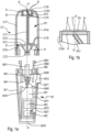
- the applicator of the invention comprises two distinct modules, namely a first module M and a second module C1, which can be connected and disconnected simply and quickly, by the user himself, for example using both hands by applying a torque and/or a push/pull between the two modules.
- the applicator has a general configuration in the shape of a pen with a longitudinal axis the index finger resting on the applicator.
- the first module M comprises an external shell M7 of substantially cylindrical or slightly frustoconical shape. Its cross section can be substantially triangular in shape.
- the M7 hull is open at its upper end and closed at its lower end by an M70 bottom insert.
- the M7 shell can include two side windows M71 and M72 for receiving two control buttons M71 and M21, as will be seen below.
- the first module M contains a motor M1, which is preferably an electric motor. It can be a small rotary motor which drives an M10 shaft to rotate on itself. We can also provide an electromagnet motor, a linear motor or a piezoelectric.
- the M1 motor is powered by an M2 battery and controlled by M3 electronics, which will manage the rotation speed of the M10 shaft, the sequences and activation times of the motor, etc.
- An external activation button M21 accessible through the side window M71 located near the bottom M70, allows the user to turn on the applicator.
- the free end of the M10 shaft is capped with an M4 wobble cap, which forms an M40 inclined cam surface. The rotation of the M10 shaft causes this inclined cam surface to rotate on itself, thus describing a rotating wobbly movement.
- the motor M1, the battery M2, the electronics M3 and the oscillating cap M4 are mounted on a mobile carriage M11 along the longitudinal axis X.
- the mobile carriage M11 includes a selection cursor M12, accessible through the side window M72, which allows the user to set or adjust the penetration depth of the microneedles, as discussed below.
- the mobile cart is however optional.
- the first module M also includes a piston M4 which moves axially back and forth.
- the M4 piston forms an inclined underside M50 which is engaged with the M40 inclined cam surface of the M4 wobble cap.
- the piston M5 is locked in rotation, so that the inclined lower face M50 remains static, while the inclined cam surface M40 is rotated by the motor M1. It follows that the piston M5 is driven in axial movement, due to the vacillating contact between the cam surface M40 and the inclined face M50.
- the piston M5 comprises a transmission head M51, located opposite the inclined face M50, which therefore moves axially back and forth, when the motor M1 is activated.
- the first module M also includes an M6 connection end which forms an M60 connection socket provided with M61 connection profiles.
- the M6 connection end is fixedly mounted in the M7 shell, for example by snap-fastening.
- the M6 connection piece is crossed by the M5 piston, whose transmission head M51 extends into the M60 connection socket.
- the M5 piston can be guided axially in the M6 connection end, so as to block it from rotating. We can thus say that the piston M5 slides axially back and forth in the connection end M6.
- the axial stroke of the M5 piston is, however, limited downwards by the M4 wobble cap and upwards by the M6 connection piece.
- the M5 piston is therefore stuck between the M4 cap and the M6 end piece with a purely axial degree of freedom, imposed by the M4 wobbly cap.
- the piston stroke can be increased or reduced by acting on the selection slider M12, which moves the wobble cap M4 relative to the connection tip M6, which remains fixed.
- this first module M contains expensive organs and components, which are intended to be preserved over an extended period of time.
- the second module C1 of this first embodiment comprises an external envelope C17 of substantially cylindrical or slightly frustoconical shape. Its cross section can be of substantially triangular shape, complementary to that of the shell M7 of the first module M.
- the envelope C17 forms a central window C18 at its upper end and is open at its lower end.
- the central window C18 can form an axial guide cylinder 181.
- the envelope C17 includes a side window C19 for receiving the actuating member R10 of the tank R, as will be seen below.
- the second module C1 comprises a plate P forming an external application face PO on which microneedles N are arranged.
- Their number can vary from 5 to 100.
- Their thickness can vary from 0.05 to 0.5 mm.
- Their length can vary from 0.1 to 0.7 mm. These values are given for purely indicative purposes.
- the plate P is crossed by a fluid product outlet O, which can be central or offset. It is also possible to provide several fluid product outlets, for example arranged in a circle.
- the outlet of fluid product can also be done at the periphery of the plate P. Optionally, the outlets can be done through hollow micro-needles.
- the design of the application face PO is not critical for the invention, insofar as it presents micro-needles N and allows the distribution of fluid product.
- the plate P is mounted on or in a support ring B to which is fixed a transmission rod C11, which extends axially in a centered manner.
- the transmission rod C11 comprises a contact heel C12 intended to come into pressed contact with the transmission head M51 of the first module M.
- the second module C1 also includes a connection sleeve D which is fixedly mounted in the lower opening of the external envelope C17, for example by snap-fastening.
- This sleeve D includes a housing D10 connection suitable for receiving the M61 connection profiles of the M60 connection socket.
- the sleeve D also includes an annular flange D11 which forms a central passage D12, through which the transmission rod C11 passes.
- the contact heel C12 is arranged in the sleeve D, with a return spring S bearing between the heel C11 and the flange D11, so that the plate P is biased towards the inside of the window C18.
- the second module C1 also includes a reservoir of cosmetic fluid product R1 which is connected to the fluid product outlet O by a supply conduit R11.
- the tank R1 includes an actuation wall R10 which is accessible through the side window C19 of the envelope C17.
- the R10 actuation wall is deformable, elastically or permanently. Pressure exerted by a finger of the user, generally the index finger, has the effect of reducing the useful volume of the reservoir R1 and putting its contents under pressure, which results in part of its contents being pushed back through the conduit d the supply R11 which opens at the fluid product outlet O. a dose of fluid product is thus distributed on the application face PO.
- the tank R1 can be made in a single piece with a suitable plastic material, such as an elastomer. Its R10 actuating wall can have a reduced wall thickness to give it greater elasticity.
- the R1 tank is housed next to the C11 transmission rod, on the right side on the figure 1a .
- the reservoir R1 can partially or completely surround the transmission rod C11. Two opposing actuation walls could be provided, which the user could press between the thumb and the index or middle finger (unclaimed variant).
- the second module C1 due to its simplicity of design and its passivity (no electrical or electronic component), constitutes an inexpensive entity, which can be considered as a cartridge or a replaceable refill.
- the applicator can for example be sold in the form of a kit comprising a first module M and several second modules C11. Protection could be sought for such a kit.
- the second module C1 comprises an actuating member R10, in the form of the flexible wall of the reservoir R1, which makes it possible to distribute fluid product at the level of the application face PO.
- This actuator acts directly on the tank R1, without any intermediary. It is accessible when the two modules are connected to each other. The user can operate it manually using one or more fingers.
- connection socket M60 To connect the second module C1 to the first module M, simply engage the connection socket M60 axially in the connection sleeve D. In doing so, the transmission head M51 of the piston M5 will come into contact with the contact heel C12 of the transmission rod C11. Spring S will eventually be compressed.
- the M61 connection profiles abut against the annular flange D11, the user can perform a rotating movement on one of the modules to lock the M61 connection profiles in the D10 connection housing of the sleeve D. A slight " click » tactile and/or audible may indicate that the connection is complete.
- the user can then select the penetration depth of the microneedles by acting on the M12 cursor. It can press on the actuation wall R10 to distribute a dose of cosmetic fluid product at the level of the application face PO. Pressing the activation button M21 puts the motor into action, which has the effect of rotating the oscillating cap M4, which will move the piston M5 back and forth axially, which will press on the heel C12 to against the spring S.
- the rod C11 transmits the vibration to the plate P with its micro-needles N, which will pierce the surface layer of the user's skin, which is already coated with cosmetic fluid product. The fluid product thus penetrates the skin superficially for enhanced action.
- the second module of the applicator particularly in level of the fluid reservoir, its actuating member and the transmission of vibration between the contact heel and the plate.
- the purpose of these embodiments is to show that the tank can be operated in various ways and even perform a transmission function. Vibrations can also be used to distribute fluid from the reservoir.
- the second modules of figures 5 to 9 are adapted to be connected to the first module M of the first embodiment.
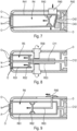
- a second module C2 with a plate P and a sleeve D comparable or identical to that of the first embodiment.
- the R2 tank is different, since it is rigid, but comprising two R23 compartments separated by an R22 partition, which still allows communication between them.
- This C2 module includes two R20 pushers connected respectively to two R21 pistons. By pressing an R20 pusher, a dose of fluid product is delivered through the plate P. The dose corresponds to approximately half the capacity of the reservoir. Of course, only one R20 pusher can be provided, or on the contrary more than two.
- the reservoir R2 which fulfills the function of the transmission rod C11 of the first embodiment by transmitting to the plate P the vibrations received by the contact heel C12.
- the compartmentalized tank can be formed by a flexible pocket which is crushed with the pistons R21.
- the tank R3 comprises a flexible pocket which can be crushed by means of a sliding slider R30.
- the flexible pocket rests on a transmission plate C31, which performs the same function as the transmission rod C11 of the first embodiment.
- the movement of the sliding cursor R30 can be perfectly linear or, on the contrary, jerky with notches to delimit doses of fluid product.
- the tank R4 comprises a sliding barrel R41, which is mounted so as to be able to pivot slightly while being connected to the plate P.
- the barrel R41 includes a beveled bottom R42 which can selectively come into contact with a beveled surface C43 of the contact heel C42.
- a pusher R40 makes it possible to rotate the barrel R41 to bring the bottom R41 into contact with the beveled surface C43 and thus establish transmission continuity.
- the barrel contains a pusher piston R43 which moves in the barrel R41 towards the plate P with the vibrations generated by the first module M.
- the reservoir R4 thus fulfills an engageable/disengageable vibration transmission function by pressing on the pusher.
- the reservoir R5 comprises a sliding barrel R51, which also fulfils a vibration transmission function.
- the barrel R51 contains a pusher piston R52 which is movable in the barrel by means of a threaded rod R53 which is engaged with a rotating actuating ring R50.
- the displacement of the rotating ring R50 can be linear or notched.
- rotating ring can act on the push piston of the tank via a rack.
- rotating ring R50 is used to twist a flexible pocket, which can extend next to or around the transmission rod C11.
- the tank R6 comprises a sliding barrel R61, which also fulfills a vibration transmission function.
- the barrel R61 contains a pusher piston R62 which can be moved in the barrel by means of a sliding slider R60 connected to the pusher piston R62 by a rod R63.
- the tank R1, R2, R3, R4, R5, R6 can perform different functions, in addition to its basic function. It can transmit vibrations to the micro-needles, serve as a clutch, as a transmission variator or even as a variator for the penetration of the micro-needles.
- the second module C1, C2, C3, C4, C5, C6 comprises an actuator member R10, R20, R30, R40, R50, R60 which is accessible and manipulatable by hand, even when the second module is connected to the first module.
- the actuating member can be presented in different forms (pusher, sliding slider, ring rotary) and moves either perpendicular to the longitudinal axis X, or axially, or in rotation. There may be several actuating members (R20) to delimit doses. The movement of the actuating member can also be notched.
- the actuating member may be an integral part of the reservoir or constitute a member associated with the reservoir.
- the fluid product outlet O can be central, offset, arranged in a single circle or concentric.
- the fluid product outlet O extends all around the plate P which supports the micro-needles N. this plate is mounted in the sliding barrel R61.
- a cosmetic product applicator with vibrating micro-needles which is designed in two separable modules, namely a “motor” module and a “reservoir/micro-needles” module which can be consider it as a cartridge or refill, whose design is simple, which makes it inexpensive and therefore disposable.
Landscapes
- Health & Medical Sciences (AREA)
- Engineering & Computer Science (AREA)
- Animal Behavior & Ethology (AREA)
- General Health & Medical Sciences (AREA)
- Biomedical Technology (AREA)
- Heart & Thoracic Surgery (AREA)
- Hematology (AREA)
- Life Sciences & Earth Sciences (AREA)
- Veterinary Medicine (AREA)
- Anesthesiology (AREA)
- Public Health (AREA)
- Dermatology (AREA)
- Medical Informatics (AREA)
- Vascular Medicine (AREA)
- Media Introduction/Drainage Providing Device (AREA)
- Percussion Or Vibration Massage (AREA)
Applications Claiming Priority (2)
| Application Number | Priority Date | Filing Date | Title |
|---|---|---|---|
| FR2005785A FR3110854B1 (fr) | 2020-06-02 | 2020-06-02 | Applicateur à micro-aiguilles |
| PCT/FR2021/050990 WO2021245348A1 (fr) | 2020-06-02 | 2021-06-01 | Applicateur a micro-aiguilles |
Publications (2)
| Publication Number | Publication Date |
|---|---|
| EP4157425A1 EP4157425A1 (fr) | 2023-04-05 |
| EP4157425B1 true EP4157425B1 (fr) | 2024-08-07 |
Family
ID=72560758
Family Applications (1)
| Application Number | Title | Priority Date | Filing Date |
|---|---|---|---|
| EP21734427.4A Active EP4157425B1 (fr) | 2020-06-02 | 2021-06-01 | Applicateur a micro-aiguilles |
Country Status (8)
| Country | Link |
|---|---|
| US (1) | US20230264005A1 (es) |
| EP (1) | EP4157425B1 (es) |
| JP (1) | JP7685528B2 (es) |
| KR (1) | KR20230017315A (es) |
| CN (1) | CN115697459A (es) |
| ES (1) | ES2987296T3 (es) |
| FR (1) | FR3110854B1 (es) |
| WO (1) | WO2021245348A1 (es) |
Families Citing this family (1)
| Publication number | Priority date | Publication date | Assignee | Title |
|---|---|---|---|---|
| FR3161860A1 (fr) | 2024-05-03 | 2025-11-07 | Aptar France Sas | Applicateur à micro-aiguilles |
Citations (1)
| Publication number | Priority date | Publication date | Assignee | Title |
|---|---|---|---|---|
| KR101492732B1 (ko) * | 2013-09-24 | 2015-02-12 | 이만규 | 피부 치료기 |
Family Cites Families (9)
| Publication number | Priority date | Publication date | Assignee | Title |
|---|---|---|---|---|
| WO2006016647A1 (ja) * | 2004-08-12 | 2006-02-16 | Hisamitsu Pharmaceutical Co., Inc. | マイクロニードル付き経皮薬物投与装置 |
| EP3073263B1 (en) * | 2009-02-13 | 2020-04-29 | The Regents of the University of California | Device, composition and method for tissue-based diagnosis |
| US9017289B2 (en) * | 2010-11-03 | 2015-04-28 | Covidien Lp | Transdermal fluid delivery device |
| WO2014158880A1 (en) * | 2013-03-14 | 2014-10-02 | Brigham And Women's Hospital, Inc. | System and method for a laparoscopic morcellator |
| CN204293680U (zh) * | 2014-11-14 | 2015-04-29 | 广州梓煊美容器材有限公司 | 一种皮肤微针美容仪 |
| US10220195B2 (en) * | 2016-06-08 | 2019-03-05 | Eclipse Medcorp, Llc | Radio frequency needling device for use with disposable needle cartridges |
| CN108434593A (zh) * | 2018-05-31 | 2018-08-24 | 浙江指云信息技术有限公司 | 一种微晶导入仪 |
| CN109395240A (zh) * | 2018-12-18 | 2019-03-01 | 威海康博尔生物药业有限公司 | 多功能给药理疗装置 |
| CN110665111A (zh) * | 2019-10-24 | 2020-01-10 | 深圳市米丽美容科技有限公司 | 一种导入美肤仪 |
-
2020
- 2020-06-02 FR FR2005785A patent/FR3110854B1/fr active Active
-
2021
- 2021-06-01 ES ES21734427T patent/ES2987296T3/es active Active
- 2021-06-01 EP EP21734427.4A patent/EP4157425B1/fr active Active
- 2021-06-01 JP JP2022574510A patent/JP7685528B2/ja active Active
- 2021-06-01 CN CN202180039363.4A patent/CN115697459A/zh active Pending
- 2021-06-01 US US18/007,666 patent/US20230264005A1/en active Pending
- 2021-06-01 KR KR1020227046319A patent/KR20230017315A/ko active Pending
- 2021-06-01 WO PCT/FR2021/050990 patent/WO2021245348A1/fr not_active Ceased
Patent Citations (1)
| Publication number | Priority date | Publication date | Assignee | Title |
|---|---|---|---|---|
| KR101492732B1 (ko) * | 2013-09-24 | 2015-02-12 | 이만규 | 피부 치료기 |
Also Published As
| Publication number | Publication date |
|---|---|
| JP2023529852A (ja) | 2023-07-12 |
| JP7685528B2 (ja) | 2025-05-29 |
| FR3110854B1 (fr) | 2022-06-24 |
| US20230264005A1 (en) | 2023-08-24 |
| ES2987296T3 (es) | 2024-11-14 |
| KR20230017315A (ko) | 2023-02-03 |
| FR3110854A1 (fr) | 2021-12-03 |
| CN115697459A (zh) | 2023-02-03 |
| WO2021245348A1 (fr) | 2021-12-09 |
| EP4157425A1 (fr) | 2023-04-05 |
Similar Documents
| Publication | Publication Date | Title |
|---|---|---|
| EP1728494B1 (fr) | Ensemble de massage et ou de distribution | |
| EP3337443B1 (fr) | Appareil de massage muni d'au moins une composition cosmetique, dermatologique et/ou pharmaceutique | |
| CA2655510C (fr) | Dispositif de traitement, notamment de massage, du tissu conjonctif de la peau | |
| EP1169938B1 (fr) | Dispositif de conditionnement et d'application d'un produit cosmétique | |
| CA2679152C (fr) | Dispositif d'ejection jetable d'un produit liquide ou pateux | |
| EP3614990B1 (fr) | Tete de massage et appareil de massage mettant en oeuvre une telle tete | |
| EP2735297A2 (fr) | Appareil de massage avec tête de massage équipee de rouleaux de massage | |
| EP2735298B1 (fr) | Appareil de massage avec tête de massage équipee d'embouts se déplacant vers le centre de la tête | |
| EP4157425B1 (fr) | Applicateur a micro-aiguilles | |
| EP1634616A1 (fr) | Dispositif d'application d'un produit muni d'un organe d'application amovible | |
| EP2854694B1 (fr) | Piece a main pour traitement endodontique | |
| EP2735295B1 (fr) | Appareil de massage équipe d'un système de distribution de produits cosmétiques | |
| EP1728495B1 (fr) | Ensemble de massage et ou de distribution | |
| EP4291281B1 (fr) | Applicateur a micro-aiguilles | |
| EP4157424B1 (fr) | Applicateur a micro-aiguilles | |
| EP1842520A1 (fr) | Dispositif vibrant de traitement cosmétique ou de soin esthétique et appareil de stockage ou d'application d'un produit cosmétique ou de soin pourvu d'un tel dispositif | |
| FR2942943A1 (fr) | Dispositif d'application comportant une source vibrante | |
| FR2863838A1 (fr) | Boitier comportant un tiroir et un miroir articule sur ce tiroir | |
| EP0028173A1 (fr) | Appareil pour l'application d'un produit liquide ou pâteux | |
| FR2943223A1 (fr) | Dispositif de conditionnement comportant un systeme electrique. | |
| FR2962031A1 (fr) | Dispositif de massage | |
| EP3072546A1 (fr) | Porte seringue pour dispositif d'injection motorisé | |
| WO2025229164A1 (fr) | Applicateur à micro-aiguilles | |
| FR2999888A1 (fr) | Embout a soufflet pour dispositif cosmetique | |
| FR3074656A1 (fr) | Dispositif de conditionnement et d'application d'un produit cosmetique fluide |
Legal Events
| Date | Code | Title | Description |
|---|---|---|---|
| STAA | Information on the status of an ep patent application or granted ep patent |
Free format text: STATUS: UNKNOWN |
|
| STAA | Information on the status of an ep patent application or granted ep patent |
Free format text: STATUS: THE INTERNATIONAL PUBLICATION HAS BEEN MADE |
|
| PUAI | Public reference made under article 153(3) epc to a published international application that has entered the european phase |
Free format text: ORIGINAL CODE: 0009012 |
|
| STAA | Information on the status of an ep patent application or granted ep patent |
Free format text: STATUS: REQUEST FOR EXAMINATION WAS MADE |
|
| 17P | Request for examination filed |
Effective date: 20221228 |
|
| AK | Designated contracting states |
Kind code of ref document: A1 Designated state(s): AL AT BE BG CH CY CZ DE DK EE ES FI FR GB GR HR HU IE IS IT LI LT LU LV MC MK MT NL NO PL PT RO RS SE SI SK SM TR |
|
| DAV | Request for validation of the european patent (deleted) | ||
| DAX | Request for extension of the european patent (deleted) | ||
| GRAP | Despatch of communication of intention to grant a patent |
Free format text: ORIGINAL CODE: EPIDOSNIGR1 |
|
| STAA | Information on the status of an ep patent application or granted ep patent |
Free format text: STATUS: GRANT OF PATENT IS INTENDED |
|
| INTG | Intention to grant announced |
Effective date: 20240212 |
|
| P01 | Opt-out of the competence of the unified patent court (upc) registered |
Effective date: 20240318 |
|
| GRAS | Grant fee paid |
Free format text: ORIGINAL CODE: EPIDOSNIGR3 |
|
| GRAA | (expected) grant |
Free format text: ORIGINAL CODE: 0009210 |
|
| STAA | Information on the status of an ep patent application or granted ep patent |
Free format text: STATUS: THE PATENT HAS BEEN GRANTED |
|
| AK | Designated contracting states |
Kind code of ref document: B1 Designated state(s): AL AT BE BG CH CY CZ DE DK EE ES FI FR GB GR HR HU IE IS IT LI LT LU LV MC MK MT NL NO PL PT RO RS SE SI SK SM TR |
|
| REG | Reference to a national code |
Ref country code: GB Ref legal event code: FG4D Free format text: NOT ENGLISH |
|
| REG | Reference to a national code |
Ref country code: CH Ref legal event code: EP |
|
| REG | Reference to a national code |
Ref country code: IE Ref legal event code: FG4D Free format text: LANGUAGE OF EP DOCUMENT: FRENCH |
|
| REG | Reference to a national code |
Ref country code: DE Ref legal event code: R096 Ref document number: 602021016869 Country of ref document: DE |
|
| REG | Reference to a national code |
Ref country code: ES Ref legal event code: FG2A Ref document number: 2987296 Country of ref document: ES Kind code of ref document: T3 Effective date: 20241114 |
|
| REG | Reference to a national code |
Ref country code: LT Ref legal event code: MG9D |
|
| REG | Reference to a national code |
Ref country code: NL Ref legal event code: MP Effective date: 20240807 |
|
| PG25 | Lapsed in a contracting state [announced via postgrant information from national office to epo] |
Ref country code: NO Free format text: LAPSE BECAUSE OF FAILURE TO SUBMIT A TRANSLATION OF THE DESCRIPTION OR TO PAY THE FEE WITHIN THE PRESCRIBED TIME-LIMIT Effective date: 20241107 |
|
| REG | Reference to a national code |
Ref country code: AT Ref legal event code: MK05 Ref document number: 1710279 Country of ref document: AT Kind code of ref document: T Effective date: 20240807 |
|
| PG25 | Lapsed in a contracting state [announced via postgrant information from national office to epo] |
Ref country code: GR Free format text: LAPSE BECAUSE OF FAILURE TO SUBMIT A TRANSLATION OF THE DESCRIPTION OR TO PAY THE FEE WITHIN THE PRESCRIBED TIME-LIMIT Effective date: 20241108 Ref country code: NL Free format text: LAPSE BECAUSE OF FAILURE TO SUBMIT A TRANSLATION OF THE DESCRIPTION OR TO PAY THE FEE WITHIN THE PRESCRIBED TIME-LIMIT Effective date: 20240807 Ref country code: FI Free format text: LAPSE BECAUSE OF FAILURE TO SUBMIT A TRANSLATION OF THE DESCRIPTION OR TO PAY THE FEE WITHIN THE PRESCRIBED TIME-LIMIT Effective date: 20240807 Ref country code: PT Free format text: LAPSE BECAUSE OF FAILURE TO SUBMIT A TRANSLATION OF THE DESCRIPTION OR TO PAY THE FEE WITHIN THE PRESCRIBED TIME-LIMIT Effective date: 20241209 Ref country code: PL Free format text: LAPSE BECAUSE OF FAILURE TO SUBMIT A TRANSLATION OF THE DESCRIPTION OR TO PAY THE FEE WITHIN THE PRESCRIBED TIME-LIMIT Effective date: 20240807 |
|
| PG25 | Lapsed in a contracting state [announced via postgrant information from national office to epo] |
Ref country code: BG Free format text: LAPSE BECAUSE OF FAILURE TO SUBMIT A TRANSLATION OF THE DESCRIPTION OR TO PAY THE FEE WITHIN THE PRESCRIBED TIME-LIMIT Effective date: 20240807 |
|
| PG25 | Lapsed in a contracting state [announced via postgrant information from national office to epo] |
Ref country code: LV Free format text: LAPSE BECAUSE OF FAILURE TO SUBMIT A TRANSLATION OF THE DESCRIPTION OR TO PAY THE FEE WITHIN THE PRESCRIBED TIME-LIMIT Effective date: 20240807 |
|
| PG25 | Lapsed in a contracting state [announced via postgrant information from national office to epo] |
Ref country code: IS Free format text: LAPSE BECAUSE OF FAILURE TO SUBMIT A TRANSLATION OF THE DESCRIPTION OR TO PAY THE FEE WITHIN THE PRESCRIBED TIME-LIMIT Effective date: 20241207 Ref country code: AT Free format text: LAPSE BECAUSE OF FAILURE TO SUBMIT A TRANSLATION OF THE DESCRIPTION OR TO PAY THE FEE WITHIN THE PRESCRIBED TIME-LIMIT Effective date: 20240807 |
|
| PG25 | Lapsed in a contracting state [announced via postgrant information from national office to epo] |
Ref country code: HR Free format text: LAPSE BECAUSE OF FAILURE TO SUBMIT A TRANSLATION OF THE DESCRIPTION OR TO PAY THE FEE WITHIN THE PRESCRIBED TIME-LIMIT Effective date: 20240807 |
|
| PG25 | Lapsed in a contracting state [announced via postgrant information from national office to epo] |
Ref country code: RS Free format text: LAPSE BECAUSE OF FAILURE TO SUBMIT A TRANSLATION OF THE DESCRIPTION OR TO PAY THE FEE WITHIN THE PRESCRIBED TIME-LIMIT Effective date: 20241107 |
|
| PG25 | Lapsed in a contracting state [announced via postgrant information from national office to epo] |
Ref country code: RS Free format text: LAPSE BECAUSE OF FAILURE TO SUBMIT A TRANSLATION OF THE DESCRIPTION OR TO PAY THE FEE WITHIN THE PRESCRIBED TIME-LIMIT Effective date: 20241107 Ref country code: PT Free format text: LAPSE BECAUSE OF FAILURE TO SUBMIT A TRANSLATION OF THE DESCRIPTION OR TO PAY THE FEE WITHIN THE PRESCRIBED TIME-LIMIT Effective date: 20241209 Ref country code: PL Free format text: LAPSE BECAUSE OF FAILURE TO SUBMIT A TRANSLATION OF THE DESCRIPTION OR TO PAY THE FEE WITHIN THE PRESCRIBED TIME-LIMIT Effective date: 20240807 Ref country code: NO Free format text: LAPSE BECAUSE OF FAILURE TO SUBMIT A TRANSLATION OF THE DESCRIPTION OR TO PAY THE FEE WITHIN THE PRESCRIBED TIME-LIMIT Effective date: 20241107 Ref country code: NL Free format text: LAPSE BECAUSE OF FAILURE TO SUBMIT A TRANSLATION OF THE DESCRIPTION OR TO PAY THE FEE WITHIN THE PRESCRIBED TIME-LIMIT Effective date: 20240807 Ref country code: LV Free format text: LAPSE BECAUSE OF FAILURE TO SUBMIT A TRANSLATION OF THE DESCRIPTION OR TO PAY THE FEE WITHIN THE PRESCRIBED TIME-LIMIT Effective date: 20240807 Ref country code: IS Free format text: LAPSE BECAUSE OF FAILURE TO SUBMIT A TRANSLATION OF THE DESCRIPTION OR TO PAY THE FEE WITHIN THE PRESCRIBED TIME-LIMIT Effective date: 20241207 Ref country code: HR Free format text: LAPSE BECAUSE OF FAILURE TO SUBMIT A TRANSLATION OF THE DESCRIPTION OR TO PAY THE FEE WITHIN THE PRESCRIBED TIME-LIMIT Effective date: 20240807 Ref country code: GR Free format text: LAPSE BECAUSE OF FAILURE TO SUBMIT A TRANSLATION OF THE DESCRIPTION OR TO PAY THE FEE WITHIN THE PRESCRIBED TIME-LIMIT Effective date: 20241108 Ref country code: FI Free format text: LAPSE BECAUSE OF FAILURE TO SUBMIT A TRANSLATION OF THE DESCRIPTION OR TO PAY THE FEE WITHIN THE PRESCRIBED TIME-LIMIT Effective date: 20240807 Ref country code: BG Free format text: LAPSE BECAUSE OF FAILURE TO SUBMIT A TRANSLATION OF THE DESCRIPTION OR TO PAY THE FEE WITHIN THE PRESCRIBED TIME-LIMIT Effective date: 20240807 Ref country code: AT Free format text: LAPSE BECAUSE OF FAILURE TO SUBMIT A TRANSLATION OF THE DESCRIPTION OR TO PAY THE FEE WITHIN THE PRESCRIBED TIME-LIMIT Effective date: 20240807 |
|
| PG25 | Lapsed in a contracting state [announced via postgrant information from national office to epo] |
Ref country code: DK Free format text: LAPSE BECAUSE OF FAILURE TO SUBMIT A TRANSLATION OF THE DESCRIPTION OR TO PAY THE FEE WITHIN THE PRESCRIBED TIME-LIMIT Effective date: 20240807 Ref country code: SM Free format text: LAPSE BECAUSE OF FAILURE TO SUBMIT A TRANSLATION OF THE DESCRIPTION OR TO PAY THE FEE WITHIN THE PRESCRIBED TIME-LIMIT Effective date: 20240807 |
|
| PG25 | Lapsed in a contracting state [announced via postgrant information from national office to epo] |
Ref country code: EE Free format text: LAPSE BECAUSE OF FAILURE TO SUBMIT A TRANSLATION OF THE DESCRIPTION OR TO PAY THE FEE WITHIN THE PRESCRIBED TIME-LIMIT Effective date: 20240807 |
|
| PG25 | Lapsed in a contracting state [announced via postgrant information from national office to epo] |
Ref country code: CZ Free format text: LAPSE BECAUSE OF FAILURE TO SUBMIT A TRANSLATION OF THE DESCRIPTION OR TO PAY THE FEE WITHIN THE PRESCRIBED TIME-LIMIT Effective date: 20240807 |
|
| PG25 | Lapsed in a contracting state [announced via postgrant information from national office to epo] |
Ref country code: SK Free format text: LAPSE BECAUSE OF FAILURE TO SUBMIT A TRANSLATION OF THE DESCRIPTION OR TO PAY THE FEE WITHIN THE PRESCRIBED TIME-LIMIT Effective date: 20240807 |
|
| REG | Reference to a national code |
Ref country code: DE Ref legal event code: R097 Ref document number: 602021016869 Country of ref document: DE |
|
| PLBE | No opposition filed within time limit |
Free format text: ORIGINAL CODE: 0009261 |
|
| STAA | Information on the status of an ep patent application or granted ep patent |
Free format text: STATUS: NO OPPOSITION FILED WITHIN TIME LIMIT |
|
| PGFP | Annual fee paid to national office [announced via postgrant information from national office to epo] |
Ref country code: DE Payment date: 20250617 Year of fee payment: 5 |
|
| 26N | No opposition filed |
Effective date: 20250508 |
|
| PGFP | Annual fee paid to national office [announced via postgrant information from national office to epo] |
Ref country code: FR Payment date: 20250627 Year of fee payment: 5 |
|
| PG25 | Lapsed in a contracting state [announced via postgrant information from national office to epo] |
Ref country code: SE Free format text: LAPSE BECAUSE OF FAILURE TO SUBMIT A TRANSLATION OF THE DESCRIPTION OR TO PAY THE FEE WITHIN THE PRESCRIBED TIME-LIMIT Effective date: 20240807 |
|
| PGFP | Annual fee paid to national office [announced via postgrant information from national office to epo] |
Ref country code: ES Payment date: 20250710 Year of fee payment: 5 |
|
| REG | Reference to a national code |
Ref country code: CH Ref legal event code: H13 Free format text: ST27 STATUS EVENT CODE: U-0-0-H10-H13 (AS PROVIDED BY THE NATIONAL OFFICE) Effective date: 20260127 |
|
| PG25 | Lapsed in a contracting state [announced via postgrant information from national office to epo] |
Ref country code: MC Free format text: LAPSE BECAUSE OF FAILURE TO SUBMIT A TRANSLATION OF THE DESCRIPTION OR TO PAY THE FEE WITHIN THE PRESCRIBED TIME-LIMIT Effective date: 20240807 |
|
| PG25 | Lapsed in a contracting state [announced via postgrant information from national office to epo] |
Ref country code: LU Free format text: LAPSE BECAUSE OF NON-PAYMENT OF DUE FEES Effective date: 20250601 |
|
| GBPC | Gb: european patent ceased through non-payment of renewal fee |
Effective date: 20250601 |
|
| REG | Reference to a national code |
Ref country code: BE Ref legal event code: MM Effective date: 20250630 |
|
| PG25 | Lapsed in a contracting state [announced via postgrant information from national office to epo] |
Ref country code: GB Free format text: LAPSE BECAUSE OF NON-PAYMENT OF DUE FEES Effective date: 20250601 |
|
| PG25 | Lapsed in a contracting state [announced via postgrant information from national office to epo] |
Ref country code: IE Free format text: LAPSE BECAUSE OF NON-PAYMENT OF DUE FEES Effective date: 20250601 |
|
| PG25 | Lapsed in a contracting state [announced via postgrant information from national office to epo] |
Ref country code: BE Free format text: LAPSE BECAUSE OF NON-PAYMENT OF DUE FEES Effective date: 20250630 Ref country code: RO Free format text: LAPSE BECAUSE OF FAILURE TO SUBMIT A TRANSLATION OF THE DESCRIPTION OR TO PAY THE FEE WITHIN THE PRESCRIBED TIME-LIMIT Effective date: 20240807 Ref country code: IT Free format text: LAPSE BECAUSE OF NON-PAYMENT OF DUE FEES Effective date: 20250601 |
|
| PG25 | Lapsed in a contracting state [announced via postgrant information from national office to epo] |
Ref country code: CH Free format text: LAPSE BECAUSE OF NON-PAYMENT OF DUE FEES Effective date: 20250630 |