EP4156877A1 - Zierteil, gehäuse einer elektronischen vorrichtung und elektronische vorrichtung - Google Patents
Zierteil, gehäuse einer elektronischen vorrichtung und elektronische vorrichtung Download PDFInfo
- Publication number
- EP4156877A1 EP4156877A1 EP22798048.9A EP22798048A EP4156877A1 EP 4156877 A1 EP4156877 A1 EP 4156877A1 EP 22798048 A EP22798048 A EP 22798048A EP 4156877 A1 EP4156877 A1 EP 4156877A1
- Authority
- EP
- European Patent Office
- Prior art keywords
- structural part
- hole
- bearing layer
- hole segment
- layer
- Prior art date
- Legal status (The legal status is an assumption and is not a legal conclusion. Google has not performed a legal analysis and makes no representation as to the accuracy of the status listed.)
- Pending
Links
- 238000005034 decoration Methods 0.000 claims abstract description 131
- 239000000853 adhesive Substances 0.000 claims description 41
- 230000001070 adhesive effect Effects 0.000 claims description 41
- 239000002131 composite material Substances 0.000 claims description 22
- 239000010985 leather Substances 0.000 claims description 16
- 241000196324 Embryophyta Species 0.000 claims description 6
- 210000004207 dermis Anatomy 0.000 claims description 6
- 229920000049 Carbon (fiber) Polymers 0.000 claims description 4
- VYPSYNLAJGMNEJ-UHFFFAOYSA-N Silicium dioxide Chemical compound O=[Si]=O VYPSYNLAJGMNEJ-UHFFFAOYSA-N 0.000 claims description 4
- 229920006231 aramid fiber Polymers 0.000 claims description 4
- 239000004917 carbon fiber Substances 0.000 claims description 4
- 239000003365 glass fiber Substances 0.000 claims description 4
- 239000000741 silica gel Substances 0.000 claims description 4
- 229910002027 silica gel Inorganic materials 0.000 claims description 4
- VNWKTOKETHGBQD-UHFFFAOYSA-N methane Chemical compound C VNWKTOKETHGBQD-UHFFFAOYSA-N 0.000 claims description 3
- 230000000149 penetrating effect Effects 0.000 claims description 3
- 238000005516 engineering process Methods 0.000 abstract description 10
- 238000004519 manufacturing process Methods 0.000 description 17
- 239000000243 solution Substances 0.000 description 14
- 239000000835 fiber Substances 0.000 description 12
- 238000010586 diagram Methods 0.000 description 9
- 230000000694 effects Effects 0.000 description 9
- 239000011159 matrix material Substances 0.000 description 9
- 238000000034 method Methods 0.000 description 9
- 230000008569 process Effects 0.000 description 9
- 230000007704 transition Effects 0.000 description 8
- 239000011347 resin Substances 0.000 description 6
- 229920005989 resin Polymers 0.000 description 6
- 238000005507 spraying Methods 0.000 description 6
- 239000004831 Hot glue Substances 0.000 description 5
- 238000001746 injection moulding Methods 0.000 description 5
- 229920001410 Microfiber Polymers 0.000 description 4
- 230000008859 change Effects 0.000 description 4
- 230000006870 function Effects 0.000 description 4
- 239000003658 microfiber Substances 0.000 description 4
- 238000012545 processing Methods 0.000 description 4
- 229920000122 acrylonitrile butadiene styrene Polymers 0.000 description 3
- XECAHXYUAAWDEL-UHFFFAOYSA-N acrylonitrile butadiene styrene Chemical compound C=CC=C.C=CC#N.C=CC1=CC=CC=C1 XECAHXYUAAWDEL-UHFFFAOYSA-N 0.000 description 3
- 239000004676 acrylonitrile butadiene styrene Substances 0.000 description 3
- 239000011248 coating agent Substances 0.000 description 3
- 238000000576 coating method Methods 0.000 description 3
- 238000005259 measurement Methods 0.000 description 3
- 239000002184 metal Substances 0.000 description 3
- 239000004033 plastic Substances 0.000 description 3
- 229920003023 plastic Polymers 0.000 description 3
- 229920003229 poly(methyl methacrylate) Polymers 0.000 description 3
- 239000004417 polycarbonate Substances 0.000 description 3
- 238000007639 printing Methods 0.000 description 3
- 239000012779 reinforcing material Substances 0.000 description 3
- 230000005236 sound signal Effects 0.000 description 3
- 239000004952 Polyamide Substances 0.000 description 2
- 230000032683 aging Effects 0.000 description 2
- 230000003666 anti-fingerprint Effects 0.000 description 2
- 230000007613 environmental effect Effects 0.000 description 2
- 239000003733 fiber-reinforced composite Substances 0.000 description 2
- 239000002649 leather substitute Substances 0.000 description 2
- 239000004973 liquid crystal related substance Substances 0.000 description 2
- 239000000463 material Substances 0.000 description 2
- 230000013011 mating Effects 0.000 description 2
- 230000035699 permeability Effects 0.000 description 2
- 229920002647 polyamide Polymers 0.000 description 2
- 229920000515 polycarbonate Polymers 0.000 description 2
- 239000004926 polymethyl methacrylate Substances 0.000 description 2
- 210000003491 skin Anatomy 0.000 description 2
- 239000007779 soft material Substances 0.000 description 2
- 239000010409 thin film Substances 0.000 description 2
- 230000009471 action Effects 0.000 description 1
- 238000013459 approach Methods 0.000 description 1
- 239000004760 aramid Substances 0.000 description 1
- 238000004364 calculation method Methods 0.000 description 1
- 239000000919 ceramic Substances 0.000 description 1
- 238000004891 communication Methods 0.000 description 1
- 238000005260 corrosion Methods 0.000 description 1
- 230000007797 corrosion Effects 0.000 description 1
- 238000009713 electroplating Methods 0.000 description 1
- 239000002657 fibrous material Substances 0.000 description 1
- 230000003862 health status Effects 0.000 description 1
- 238000010329 laser etching Methods 0.000 description 1
- 238000000465 moulding Methods 0.000 description 1
- -1 printing Substances 0.000 description 1
- 230000008093 supporting effect Effects 0.000 description 1
- 229920005992 thermoplastic resin Polymers 0.000 description 1
- 229920001187 thermosetting polymer Polymers 0.000 description 1
- 238000004804 winding Methods 0.000 description 1
Images


Classifications
-
- H—ELECTRICITY
- H05—ELECTRIC TECHNIQUES NOT OTHERWISE PROVIDED FOR
- H05K—PRINTED CIRCUITS; CASINGS OR CONSTRUCTIONAL DETAILS OF ELECTRIC APPARATUS; MANUFACTURE OF ASSEMBLAGES OF ELECTRICAL COMPONENTS
- H05K5/00—Casings, cabinets or drawers for electric apparatus
- H05K5/02—Details
- H05K5/0217—Mechanical details of casings
- H05K5/0243—Mechanical details of casings for decorative purposes
-
- H—ELECTRICITY
- H04—ELECTRIC COMMUNICATION TECHNIQUE
- H04M—TELEPHONIC COMMUNICATION
- H04M1/00—Substation equipment, e.g. for use by subscribers
- H04M1/02—Constructional features of telephone sets
- H04M1/0202—Portable telephone sets, e.g. cordless phones, mobile phones or bar type handsets
- H04M1/0279—Improving the user comfort or ergonomics
- H04M1/0283—Improving the user comfort or ergonomics for providing a decorative aspect, e.g. customization of casings, exchangeable faceplate
-
- H—ELECTRICITY
- H05—ELECTRIC TECHNIQUES NOT OTHERWISE PROVIDED FOR
- H05K—PRINTED CIRCUITS; CASINGS OR CONSTRUCTIONAL DETAILS OF ELECTRIC APPARATUS; MANUFACTURE OF ASSEMBLAGES OF ELECTRICAL COMPONENTS
- H05K5/00—Casings, cabinets or drawers for electric apparatus
- H05K5/0086—Casings, cabinets or drawers for electric apparatus portable, e.g. battery operated apparatus
Definitions
- This application relates to the field of electronic device manufacturing technologies, and in particular, to a decoration part, a housing of an electronic device, and an electronic device.
- a decoration part is an important component on a terminal product.
- a function of the component may be an appearance decoration function, and certainly also may be an identification function, for example, a LOGO, a trademark, or other identification information.
- the component is mainly used on a housing of the terminal product.
- a main objective of this application is to provide a decoration part, a housing of an electronic device, and an electronic device, so as to improve firmness of combination between the decoration part and a base layer, to avoid falling, and improve an appearance.
- the present invention uses the following technical solution.
- this application provides a decoration part for a housing of an electronic device, and the decoration part includes: a bearing layer, at least one first structural part, and at least one second structural part.
- the bearing layer includes an upper surface and a lower surface.
- the at least one first structural part is disposed on the upper surface of the bearing layer.
- An edge of an upper surface of the first structural part forms a first closed connection line, and the upper surface of the first structural part is a surface that is of the first structural part and that is away from the bearing layer.
- Each second structural part is disposed on the upper surface of the first structural part and located in a region enclosed by the first closed connection line; along a direction that is directed from the upper surface to the lower surface of the bearing layer, the second structural part includes an upper surface and a lower surface that are arranged successively, an edge of the upper surface of the second structural part forms a second closed connection line; and the first closed connection line and the second closed connection line do not overlap at least in part.
- the edge of the upper surface of the first structural part forms the first closed connection line
- the edge of the upper surface of the second structural part forms the second closed connection line
- the second structural part is located in the region enclosed by the first closed connection line
- the first structural part and the at least one second structural part may be regarded as a pattern part, and a pattern represented by the pattern part may be a letter, a Chinese character, a numeral, or another pattern.
- the pattern represented by the pattern part is a letter "O".
- the pattern part may include the first closed connection line and one second closed connection line disposed within the first closed connection line, the first closed connection line corresponds to an outer ring of the letter "O", and the second closed connection line corresponds to an inner ring of the letter "O".
- the pattern represented by the pattern part is a letter "B".
- the pattern part may include the first closed connection line and two second closed connection lines disposed within the first closed connection line, the first closed connection line corresponds to an outer ring of the letter "B", and the two second closed connection lines respectively correspond to two inner rings of the letter "B”.
- the decoration part further includes at least one third structural part disposed on the upper surface of the bearing layer, an edge of an upper surface of the third structural part forms a third closed connection line, and the upper surface of the third structural part is a surface that is of the third structural part and that is away from the bearing layer.
- a pattern represented by the third structural part includes only one closed connection line.
- the third structural part may be a pattern part of a letter "N".
- any pattern including the first closed connection line and at least one second closed connection line disposed within the first closed connection line may be regarded as a first pattern.
- letters “O”, “A”, “B”, “D”, “P”, “Q”, and “R” are all first patterns.
- Any pattern including the third closed connection line may be regarded as a second pattern.
- letters “N”, “C”, “F”, “L”, and “H” are all second patterns.
- first closed connection line and the second closed connection line do not overlap at all, and a person skilled in the art can understand that the first closed connection line and the second closed connection line may alternatively partially overlap.
- the second closed connection line in the letter "O" moves upward to partially overlap the first closed connection line, that is, the outer ring is tangent to the inner ring, and a pattern formed in this way is also applicable herein.
- the first structural part, the third structural part, and the bearing layer are of an integral structure.
- a digging hole is provided in the upper surface of the first structural part and located in the region enclosed by the first closed connection line, and the second structural part is disposed in the digging hole.
- the digging hole is formed in the upper surface of the first structural part, and the second structural part is disposed in the digging hole.
- an edge that is of the digging hole and that is on the upper surface of the first structural part may not overlap the edge of the upper surface of the second structural part; or if the upper surface of the second structural part is flush with the upper surface of the first structural part, the edge that is of the digging hole and that is on the upper surface of the first structural part may be regarded as the edge of the upper surface of the second structural part.
- the edge of the digging hole forms the second closed connection line.
- the upper surface of the second structural part may be slightly lower than the upper surface of the first structural part, and in this case, the edge of the upper surface of the second structural part forms the second closed connection line without affecting an appearance.
- the digging hole is a first groove disposed in the upper surface of the first structural part.
- the second structural part may be a coating disposed within the first groove (for example, formed through spraying).
- a depth of the first groove may be, for example, 0.02-0.5 mm.
- the digging hole is a through-hole penetrating through the upper surface of the first structural part and the lower surface of the bearing layer.
- the second structural part may be directly disposed in the through-hole by using an injection molding process or a spraying process, or may be disposed in the through-hole through mounting. This is not specifically limited herein.
- a shape of a longitudinal section of the through-hole is trapezoidal or rectangular.
- a section refers to a plane pattern obtained by using a plane to truncate a geometry.
- the through-hole is regarded as a geometry
- the longitudinal section is a plane pattern obtained by using a plane perpendicular to the upper surface of the bearing layer to truncate the through-hole.
- a longitudinal section of the second structural part and the longitudinal section of the through-hole may be of the same shape, or may be of different shapes. This is not specifically limited herein.
- the longitudinal section of the second structural part and the longitudinal section of the through-hole may be of the same shape if the second structural part is formed in the through-hole directly by using the injection molding process or the spraying process. If the second structural part is disposed in the through-hole through mounting, the longitudinal section of the second structural part and the longitudinal section of the through-hole may be of the same shape, or may be of different shapes. For example, if the shape of the longitudinal section of the through-hole is trapezoidal, the shape of the longitudinal section of the second structural part may be trapezoidal or rectangular.
- both the shape of the longitudinal section of the through-hole and the shape of the longitudinal section of the second structural part are trapezoidal.
- a position of the second structural part can be better limited, to prevent the second structural part from falling out of a side of the upper surface of the first structural part.
- a first adhesive portion is disposed between an outer wall of the second structural part and an inner wall of the through-hole, and the second structural part and the through-hole are connected by using the first adhesive portion.
- the through-hole includes a first hole segment and a second hole segment that are sequentially connected, an orthographic projection that is on the upper surface of the bearing layer and that is of an edge that is of the first hole segment and that is close to the second hole segment is located outside an orthographic projection that is on the upper surface of the bearing layer and that is of an edge that is of the second hole segment and that is close to the first hole segment, a plane portion is formed between the edge that is of the second hole segment and that is close to the first hole segment and the edge that is of the first hole segment and that is close to the second hole segment, and a shape of a longitudinal section of the first hole segment and a shape of a longitudinal section of the second hole segment are trapezoidal or rectangular.
- the orthographic projection that is on the upper surface of the bearing layer and that is of the edge that is of the first hole segment and that is close to the second hole segment is located outside the orthographic projection that is on the upper surface of the bearing layer and that is of the edge that is of the second hole segment and that is close to the first hole segment, and the plane portion is formed between the edge that is of the second hole segment and that is close to the first hole segment and the edge that is of the first hole segment and that is close to the second hole segment, a hole diameter of the second hole segment is smaller than a hole diameter of the first hole segment as a whole, and a limiting step is formed between the first hole segment and the second hole segment.
- the longitudinal section of the first hole segment and the longitudinal section of the second hole segment are trapezoidal or rectangular, the first hole segment and the second hole segment are gradually shrinking along the direction gradually away from the lower surface of the bearing layer.
- the longitudinal section of the second structural part and the longitudinal section of the through-hole may be of the same shape, or may be of different shapes.
- the second structural part may be manufactured into a stepped shape, that is, the shape of the longitudinal section of the second structural part may be the same as the shape of the longitudinal section of the through-hole.
- the second structural part may be prevented from falling out of the side of the upper surface of the first structural part when the second structural part is mounted in the through-hole.
- the second structural part is manufactured into the stepped shape, to form a grabbing portion on the second structural part, so as to facilitate grabbing during mounting.
- a second adhesive portion is disposed between the second structural part and the plane portion, and the second structural part and the through-hole are connected by using the second adhesive portion.
- the first hole segment is provided in the bearing layer and the first structural part
- the second hole segment is provided in the first structural part
- the edge that is of the first hole segment and that is close to the second hole segment is located in the region enclosed by the first closed connection line.
- That the edge that is of the first hole segment and that is close to the second hole segment is located in the region enclosed by the first closed connection line means that the orthographic projection that is on the upper surface of the bearing layer and that is of the edge that is of the first hole segment and that is close to the second hole segment and an orthographic projection that is of the first closed connection line and that is on the upper surface of the bearing layer overlap, or the orthographic projection that is on the upper surface of the bearing layer and that is of the edge that is of the first hole segment and that is close to the second hole segment is located in the region enclosed by the first closed connection line, and there is a gap between the orthographic projection that is on the upper surface of the bearing layer and that is of the edge that is of the first hole segment and that is close to the second hole segment and the orthographic projection that is of the first closed connection line and that is on the upper surface of the bearing layer.
- a depth of the first hole segment is greater than a thickness of the bearing layer
- the plane portion is disposed on the first structural part, and corresponds to a portion that is of the first structural part and that is from the edge that is of the first hole segment and that is close to the second hole segment to the edge that is of the second hole segment and that is close to the first hole segment.
- the first hole segment is provided in the bearing layer, and the edge that is of the first hole segment and that is close to the second hole segment is located in or outside the region enclosed by the first closed connection line. That the edge that is of the first hole segment and that is close to the second hole segment is located in the region enclosed by the first closed connection line means that the orthographic projection that is on the upper surface of the bearing layer and that is of the edge that is of the first hole segment and that is close to the second hole segment and an orthographic projection that is of the first closed connection line and that is on the upper surface of the bearing layer overlap, or the orthographic projection that is on the upper surface of the bearing layer and that is of the edge that is of the first hole segment and that is close to the second hole segment is located in the region enclosed by the first closed connection line, and there is a gap between the orthographic projection that is on the upper surface of the bearing layer and that is of the edge that is of the first hole segment and that is close to the second hole segment and the orthographic projection that is of the first closed connection line and
- the depth of the first hole segment is less than the thickness of the bearing layer
- the plane portion is disposed on the bearing layer, and corresponds to a portion that is of the bearing layer and that is from the edge that is of the first hole segment and that is close to the second hole segment to the edge that is of the second hole segment and that is close to the first hole segment.
- the depth of the first hole segment is equal to the thickness of the bearing layer
- the plane portion is disposed on the first structural part, and corresponds to a portion that is of the first structural part and that is from the edge that is of the first hole segment and that is close to the second hole segment to the edge that is of the second hole segment and that is close to the first hole segment.
- That the edge that is of the first hole segment and that is close to the second hole segment is located outside the region enclosed by the first closed connection line means that the orthographic projection that is on the upper surface of the bearing layer and that is of the edge that is of the first hole segment and that is close to the second hole segment is located outside the region enclosed by the first closed connection line, and there is a gap between the orthographic projection that is on the upper surface of the bearing layer and that is of the edge that is of the first hole segment and that is close to the second hole segment and the orthographic projection that is of the first closed connection line and that is on the upper surface of the bearing layer.
- an area of a portion that is of the second structural part and that is located in the first hole segment may be increased, to increase a grabbing area and improve efficiency of mounting the second structural part in the through-hole.
- each through-hole may be trapezoidal or rectangular; or each through-hole may include, along the direction gradually away from the lower surface of the bearing layer, the first hole segment and the second hole segment that are sequentially connected.
- depths of the first hole segments of all through-holes may be the same or different, and depths of the second hole segments may also be the same or different.
- the first hole segments of all through-holes are connected to each other.
- the depths of the first hole segments of all through-holes may also be the same or different, where portions that are of the plurality of second structural parts, that are located in the first hole segment and that are connected to each other each may be referred to as a connection edge, the connection edge may be disposed, for example, between two adjacent second structural parts, and the two second structural parts are connected as an integral structure by using connection edges thereof.
- a LOGO logo is letters "NOHOR"
- a longitudinal section of a through-hole in the letter “O” may be tapered or truncated cone shaped
- a longitudinal section of a through-hole in the letter “R” may also be tapered or truncated cone shaped
- a second structural part in the letter “O” and a second structural part in the letter “R” each are independent of each other.
- through-holes in the two letters "O” and the through-hole in the letter “R” each include a first hole segment and a second hole segment, and the first hole segment in the two letters "O” and the first hole segment in the letter “R” each are located outside a region thereof enclosed by the first closed connection line, and are connected as an integral structure.
- a position that is of the letter “H” in a middle of the two letters “O” and that is corresponding to the hole segment is also hollowed out, so that the edges that are of the two letters “O” and that are close to each other are opened up, and edges that are of "R” and are of "O” that is close to "R” and that are close to each other are opened up, to enable portions that are of the second structural parts in the two letters “O” and that are located in the first hole segments to cross the letter "H” and to be connected to a portion that is of the second structural part in the letter “R” and that is located in the first hole segment as an integral structure.
- Positions that are of the bearing layer and that are corresponding to the two letters "O", the letter "H”, and the letter “R” each may be hollowed out.
- a lower surface of the second structural part is flush with the lower surface of the bearing layer.
- the decoration part further includes a base, the base is disposed on a side of the lower surface of the bearing layer, and the base is connected to the at least one second structural part; and an edge of the base extends beyond an orthographic projection that is of each second structural part and that is on the upper surface of the bearing layer, a third adhesive portion is disposed between the base and the bearing layer, and the base and the bearing layer are connected by using the third adhesive portion.
- the upper surface of the second structural part is flush with the upper surface of the first structural part.
- the thickness of the bearing layer is 0.1-0.3 mm.
- a housing of an electronic device includes: a base layer, a decoration part, and a decoration layer, where an outer surface of the base layer includes a first region and a second region, and the first region and the second region are adjacent to each other; the decoration part is disposed on the outer surface of the base layer and located in the first region, where the decoration part is connected to the base layer by using a bearing layer; and the decoration layer includes a portion covering the second region and a portion covering the first region except a region enclosed by a first closed connection line. That is, the decoration layer covers the second region and a region that is of the first region and that is not covered by a first structural part and a second structural part.
- the second region may be a region on the outer surface of the base layer except the first region; that is, the decoration layer covers all regions that are of the base layer and that are not covered by the first structural part and the second structural part.
- the decorating layer includes a portion covering the second region and a portion covering the first region except a region enclosed by the first closed connection line and a third closed connection line.
- the decoration layer covers all regions that are of the base layer and that are not covered by the first structural part, the second structural part, and the third structural part.
- the decoration part is sheet-shaped and includes the bearing layer, and a LOGO pattern formed on a surface of the bearing layer by using a printing or laser process, and the LOGO pattern is a plane pattern
- the first structural part, the second structural part, and the third structural part in the decoration part have specific thicknesses, so that an overall thickness of the decoration part may be increased, thereby improving firmness of combination between the decoration part and the base layer and avoiding falling.
- the decoration part in comparison with the related technology in which the decoration part is adhered to the decoration layer by using adhesive (such as hot melt adhesive), in addition to being adhered to the base layer by using the adhesive, the decoration part may be covered by the decoration layer, so that the firmness of connection between the decoration part and the base layer may be further improved. Further, because the decoration layer covers the second region and a region that is of the first region and that is not covered by the first structural part, the second structural part, and the third structural part, the decoration layer may continuously cover at a transition position of the base layer and the bearing layer, so as to avoid forming a gap at the transition position of the base layer and the bearing layer of the decoration part.
- adhesive such as hot melt adhesive
- the first decoration layer covers the region that is of the first region and that is not covered by the first structural part, the second structural part and the third structural part, to make transition between the first decoration layer and each of the first structural part and the third structural part more natural, so as to better highlight an appearance profile of the LOGO pattern and make the LOGO display more conspicuous, thereby further improving an appearance.
- the foregoing describes a solution in which the decoration part is directly fastened to the outer surface of the base layer.
- a thickness of the base layer does not change.
- a difference is that if a portion that is of the second structural part and that is located in a first hole segment is manufactured into a base-like structure, and the portion is located on a same layer as the bearing layer, an overall thickness of the decoration part may be reduced in comparison with manufacturing the foregoing base-like structure on a side of the lower surface of the bearing layer, so that an overall thickness of the housing can be minimized.
- the solution is also suitable for manufacturing an ultra-thin base layer.
- a position that is of the outer surface of the base layer and that is corresponding to the first region is provided with a second groove, and the bearing layer is disposed in the second groove. Because the thickness of the base layer may be reduced by disposing the second groove in the base layer, the solution is not suitable for manufacturing a product with an ultra-thin base layer.
- the portion that is of the second structural part and that is located in the first hole segment is manufactured into a base-like structure, and the portion is located on the same layer as the bearing layer, a depth of the second groove may be reduced in comparison with manufacturing the foregoing base-like structure on the side of the lower surface of the bearing layer, to avoid digging through the base layer.
- an edge of an upper surface of the bearing layer is provided with a chamfer, so that the transition of a segment gap between the bearing layer and the base layer is smoother, to improve adhesion strength of the decoration layer on the base layer and the bearing layer without forming the segment gap mark on an outer surface of the first decoration layer.
- a position that is of the base layer and that is corresponding to the second groove has a protrusion towards a side that is away from the bearing layer. That is, the position that is of the base layer and that is corresponding to the second groove is thickened, to ensure that a thickened base layer has a specific thickness after the groove is cut, thereby ensuring strength of the base layer.
- a height of the protrusion is 0.05-0.2 mm.
- the base layer is an aramid fiber composite board, a glass fiber composite board, or a carbon fiber composite board, which can improve the strength of the base layer.
- the decoration layer is made of vegan leather, animal dermis, plant bark, or silica gel.
- the vegan leather is a soft material with a leather feel and appearance, is soft, durable, waterproof, and is a kind of artificial leather.
- the vegan leather is warm, skin-friendly, anti-fingerprint, anti-falling, and the like.
- the dermis is obtained by processing an animal skin, is breathable and skin-friendly, and is relatively expensive.
- the plant bark is also referred to as microfiber leather, and its full name is "microfiber reinforced leather". It has extremely excellent wear resistance, excellent air permeability, and aging resistance, is soft and comfortable, has strong flexibility, and has the currently advocated environmental protection effect.
- the base layer may alternatively be a plastic board, a metal board, or the like. This is not specifically limited herein.
- an electronic device includes the housing according to the second aspect, a display screen, and the like.
- the housing may be a rear cover of the electronic device.
- the electronic device has a same technical effect as the housing of the electronic device according to the second aspect. Details are not described herein again.
- first and second are used for descriptive purposes only, and cannot be construed as indicating or implying relative importance or implicitly indicating the quantity of technical features indicated. Therefore, the features defined with “first” and “second” may explicitly or implicitly include one or more of the features. In the descriptions of embodiments of this application, unless otherwise specified, "a plurality of" means two or more.
- phrases "at least one of A, B and C” has a same meaning as the phrase "at least one of A, B or C", and they both include the following combinations of A, B, and C: only A, only B, only C, a combination of A and B, a combination of A and C, a combination of B and C, and a combination of A, B, and C.
- a and/or B includes the following three combinations: only A, only B, and a combination of A and B.
- Exemplary embodiments are described herein with reference to sectional views and/or plan views as idealized exemplary drawings.
- thicknesses of layers and sizes of regions are enlarged for clarity. Variations in shape with respect to the accompanying drawings due to, for example, manufacturing technologies and/or tolerances may be envisaged. Therefore, the exemplary embodiments should not be construed to be limited to the shapes of the regions shown herein, but to include deviations in shape due to, for example, manufacturing.
- an etched region shown in a rectangular shape usually has a feature of being curved. Therefore, the regions shown in the accompanying drawings are schematic in nature, and their shapes are not intended to show actual shapes of the regions in a device, and are not intended to limit the scope of the exemplary embodiments.
- Some embodiments of this application provide an electronic device, including but not limited to a mobile or fixed terminal such as a mobile phone, a tablet personal computer, a notebook computer, an ultra-mobile personal computer (ultra-mobile personal computer, UMPC), a handheld computer, a walkie-talkie, a netbook, a POS terminal, a personal digital assistant (personal digital assistant, PDA), an event data recorder, a wearable device, or a virtual reality device.
- a mobile or fixed terminal such as a mobile phone, a tablet personal computer, a notebook computer, an ultra-mobile personal computer (ultra-mobile personal computer, UMPC), a handheld computer, a walkie-talkie, a netbook, a POS terminal, a personal digital assistant (personal digital assistant, PDA), an event data recorder, a wearable device, or a virtual reality device.
- a mobile or fixed terminal such as a mobile phone, a tablet personal computer, a notebook computer, an ultra-mobile personal computer (ultra-mobile personal
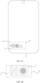
- the mobile phone 100 may include a display screen 81 and a rear cover 82; and a middle frame 83, a circuit board assembly 90, a battery 85, and a sound producing component 86 may be disposed between the display screen 81 and the rear cover 82.
- the circuit board assembly 90, the battery 85, and the sound producing component 86 may be disposed on the middle frame 83.
- the circuit board assembly 90, the battery 85, and the sound producing component 86 are disposed on a surface that is of the middle frame 83 and that faces the rear cover 82, so that the circuit board assembly 90 is located in a cavity enclosed by the rear cover 82 and the middle frame 83.
- the circuit board assembly 90, the battery 85, and the sound producing component 86 may be disposed on a surface that is of the middle frame 83 and that faces the display screen 81, so that the circuit board assembly 90 is located in a cavity enclosed by the display screen 81 and the middle frame 83.
- a battery compartment may be disposed on the surface that is of the middle frame 83 and that faces the rear cover 82, and the battery 85 is mounted in the battery compartment (as shown by a dashed-line box in FIG. 2 ) on the middle frame 83.
- the battery 85 may be connected to a charging management module and the circuit board assembly 90 by using a power management module.
- the power management module receives an input of the battery 85 and/or an input of the charging management module, and supplies power to a processor, an internal memory, an external memory, the display screen 81, a camera, a communication module, and the like.
- the power management module may be further configured to monitor parameters such as a battery capacity, a quantity of battery cycles, and a battery health status (leakage or impedance).
- the power management module may alternatively be disposed in a processor of the circuit board assembly 90.
- the power management module and the charging management module may alternatively be disposed in a same device.
- the mobile phone 100 may further include the sound producing component 86.
- the sound producing component 86 may convert an audio electrical signal into a sound signal.
- the mobile phone 100 may play music or implement hands-free calling by using the sound producing component 86.
- the sound producing component 86 may be disposed on the surface that is of the middle frame 83 and that faces the rear cover 82, so that sound producing component 86 is formed in the cavity enclosed by the rear cover 82 and the middle frame 83.
- a microphone namely, a mike, is further disposed in the mobile phone 100.
- the microphone is configured to convert a sound signal into an electrical signal.
- a user can make the user's mouth approach the microphone and emit a sound, to input a sound signal to the microphone.
- the display screen 81 may be an organic light-emitting diode (Organic Light-Emitting Diode, OLED) display screen, or may be a liquid crystal display (Liquid Crystal Display, LCD) screen. It should be understood that the display screen 81 may include a display and a touch component. The display is configured to output display content to the user, and the touch component is configured to receive a touch event entered by the user on the display screen 81.
- OLED Organic Light-Emitting Diode
- LCD liquid crystal display
- the mobile phone 100 may include more or fewer components than those shown in the figure, or combine some components, or split some components, or have different component arrangements.
- the mobile phone 100 may further include components such as a flash.
- the housing includes: a base layer 1, a first decoration layer 2, and a decoration part 3.
- the base layer 1 may include an inner surface 1a and an outer surface 1b, where the inner surface 1a is a surface that is of the base layer 1 and that faces a display screen 81, and the outer surface 1b is a surface that is of the base layer 1 and that is away from the display screen 81.
- Both the first decoration layer 2 and the decoration part 3 are disposed on the outer surface 1b of the base layer 1.
- the first decoration layer 2 may be made of vegan leather, animal dermis, plant bark, or silica gel, and the decoration part 3 may be a LOGO logo.
- the vegan leather is a soft material with a leather feel and appearance, is soft, durable, waterproof, and is a kind of artificial leather.
- the vegan leather is warm, skin-friendly, anti-fingerprint, anti-falling, and the like.
- the dermis is obtained by processing an animal skin, is breathable and skin-friendly, and is relatively expensive.
- the plant bark is also referred to as microfiber leather, and its full name is "microfiber reinforced leather". It has extremely excellent wear resistance, excellent air permeability, and aging resistance, is soft and comfortable, has strong flexibility, and has the currently advocated environmental protection effect.
- a decoration part 3 includes: a bearing layer 31, at least one first structural part 32, and at least one second structural part 33.
- the bearing layer 31 includes an upper surface 31a and a lower surface 31b.
- the at least one first structural part 32 is disposed on the upper surface 31a of the bearing layer 31, and an edge of an upper surface 32a of one first structural part 32 forms a first closed connection line 321, and the upper surface 32a of the first structural part 32 is a surface that is of the first structural part 32 and that is away from the bearing layer 31.
- Each second structural part 33 is disposed on the upper surface 32a of the first structural part 32 and located in a region enclosed by the first closed connection line 321; along a direction that is directed from the upper surface 31a to the lower surface 31b of the bearing layer 31 (as a direction indicated by arrows a in FIG. 4B and FIG. 4C ), the second structural part 33 includes an upper surface 33a and a lower surface 33b that are arranged successively, an edge of the upper surface 33a of the second structural part 33 forms a second closed connection line 331; and the first closed connection line 321 and the second closed connection line 331 do not overlap at least in part.
- the edge of the upper surface 32a of the first structural part 32 forms the first closed connection line 321
- the edge of the upper surface 33a of the second structural part 33 forms the second closed connection line 331
- the second structural part 33 is located in the region enclosed by the first closed connection line 321
- the first structural part 32 and the at least one second structural part 33 may be regarded as a pattern part, and a pattern represented by the pattern part may be a letter, a Chinese character, a numeral, or another pattern.
- the pattern represented by the pattern part is a letter "O".
- the pattern part may include the first closed connection line 321 and one second closed connection line 331 disposed within the first closed connection line 321, the first closed connection line 321 corresponds to an outer ring of the letter "O", and the second closed connection line 331 corresponds to an inner ring of the letter "O".
- the pattern represented by the pattern part is a letter "B".
- the pattern part may include the first closed connection line 321 and two second closed connection lines 331 disposed within the first closed connection line 321, the first closed connection line 321 corresponds to an outer ring of the letter "B", and the two second closed connection lines 331 respectively correspond to two inner rings of the letter "B”.
- the decoration part 3 further includes at least one third structural part 34 disposed on the upper surface 31a of the bearing layer 31.
- An edge of an upper surface 34a of one third structural part 34 forms a third closed connection line 341, and the upper surface 34a of the third structural part 34 is a surface that is of the third structural part 34 and that is away from the bearing layer 31.
- a pattern represented by the third structural part 34 includes only one closed connection line.
- the third structural part 34 may be a pattern part of a letter "N".
- any pattern including the first closed connection line 321 and at least one second closed connection line 331 disposed within the first closed connection line 321 may be regarded as a first pattern.
- letters “O”, “A”, “B”, “D”, “P”, “Q”, and “R” are all first patterns.
- Any pattern including the third closed connection line 341 may be regarded as a second pattern.
- letters “N”, “C”, “F”, “L”, and “H” are all second patterns.
- first pattern and the second pattern are letters
- all patterns other than letters also fall within the protection scope of this application, for example, the first pattern and the second pattern may also be Chinese characters or other patterns.
- first closed connection line 321 and the second closed connection line 331 do not overlap at all, and a person skilled in the art can understand that the first closed connection line 321 and the second closed connection line 331 may alternatively partially overlap.
- the second closed connection line 331 in the letter "O" moves upward, to partially overlap the first closed connection line 321, that is, the outer ring is tangent to the inner ring.
- a pattern formed in this way is applicable herein.
- the first structural part 32 and the third structural part 34 each may be, for example, plastic parts formed through injection molding; and in some embodiments, the first structural part 32, the third structural part 34, and the bearing layer 31 are of an integral structure.
- the upper surface 32a of the first structural part 32 and the upper surface 34a of the third structural part 34 are higher than the upper surface 31a of the bearing layer 31.
- the second structural part 33 may be a second decoration layer that is disposed on the upper surface 32a of the first structural part 32 and that is located in the region enclosed by the first closed connection line 321.
- the second decoration layer may be formed by using a process such as laser (laser etching), electroplating, PVD coating, printing, or thin film attaching (for example, the thin film may be made of vegan leather, animal dermis, plant bark, or silica gel). If a thickness of the second decoration layer is very thin and can be ignored, an edge of an upper surface of the second decoration layer is flush with an edge of a lower surface, that is, the edge of the upper surface 33a of the second structural part 33 may be regarded as an edge of the second decoration layer, and in this case, the edge of the second decoration layer forms the second closed connection line 331.
- a process such as laser (laser etching), electroplating, PVD coating, printing, or thin film attaching
- the thin film may be made of vegan leather, animal dermis, plant bark, or silica gel.
- a digging hole 35 is provided in the upper surface 32a of the first structural part 32 and located in the region enclosed by the first closed connection line 321, and the second structural part 33 is disposed in the digging hole 35.
- the digging hole 35 is formed in the upper surface 32a of the first structural part 32, and the second structural part 33 is disposed in the digging hole 35. Therefore, if the upper surface 33a of the second structural part 33 protrudes out of the digging hole 35, an edge that is of the digging hole 35 and that is on the upper surface 32a of the first structural part 32 may not overlap the edge of the upper surface of the second structural part 33, ; or if the upper surface 33a of the second structural part 33 is flush with the upper surface 32a of the first structural part 32, the edge that is of the digging hole 35 and that is on the upper surface 32a of the first structural part 32 may be regarded as the edge of the upper surface 33a of the second structural part 33.
- the edge of the digging hole 35 forms the second closed connection line 331.
- the upper surface 33a of the second structural part 33 may be slightly lower than the upper surface 32a of the first structural part 32, and in this case, the edge of the upper surface 33a of the second structural part 33 forms the second closed connection line 331 without affecting an appearance.
- the digging hole 35 is a first groove 351 disposed in the upper surface 32a of the first structural part 32.
- the second structural part 33 may be a coating disposed within the first groove 351 (for example, formed through spraying).
- a depth of the first groove 351 may be, for example, 0.02-0.5 mm.
- the digging hole 35 is a through-hole 352 penetrating through the upper surface 32a of the first structural part 32 and the lower surface 31b of the bearing layer 31.
- the second structural part 33 may be formed in the through-hole 352 directly by using an injection molding process or a spraying process, or may be disposed in the through-hole 352 through mounting. This is not specifically limited herein.
- a longitudinal section of the through-hole 352 is trapezoidal or rectangular.
- a section refers to a plane pattern obtained by using a plane to truncate a geometry.
- the through-hole 352 is regarded as a geometry
- the longitudinal section is a plane pattern obtained by using a plane perpendicular to the upper surface 31a of the bearing layer 31 to truncate the through-hole 352.
- a longitudinal section of the second structural part 33 and the longitudinal section of the through-hole 352 may be of the same shape, or may be of different shapes. This is not specifically limited herein.
- a person skilled in the art can understand that the longitudinal section of the second structural part 33 and the longitudinal section of the through-hole 352 may be of the same shape if the second structural part 33 is formed in the through-hole 352 directly by using an injection molding process or a spraying process. If the second structural part 33 is disposed in the through-hole 352 through mounting, the longitudinal section of the second structural part 33 and the longitudinal section of the through-hole 352 may be of the same shape, or may be of different shapes. For example, if the shape of the longitudinal section of the through-hole 352 is trapezoidal, the shape of the longitudinal section of the second structural part 33 may be trapezoidal or rectangular.
- the shape of the longitudinal section of the through-hole 352 and the shape of the longitudinal section of the second structural part 33 each are trapezoidal. Compared with a case in which the shape of the longitudinal section of the second structural part 33 is rectangular, a position of the second structural part 33 can be better limited, to prevent the second structural part 33 from falling out of a side of the upper surface 32a of the first structural part 32.
- a first adhesive portion 4 is disposed between an outer wall of the second structural part 33 and an inner wall of the through-hole 352, and the second structural part 33 and the through-hole 352 are connected by using the first adhesive portion 4.
- the first adhesive portion 4 may be hot melt adhesive.
- the through-digging hole 352 includes a first hole segment 352A and a second hole segment 352B that are sequentially connected, an orthographic projection that is on the upper surface 31a of the bearing layer 31 and that is of an edge that is of the first hole segment 352A and that is close to the second hole segment 352B is located outside an orthographic projection that is on the upper surface 31a of the bearing layer 31 and that is of an edge that is of the second hole segment 352B and that is close to the first hole segment 352A, a plane portion F is formed between the edge that is of the second hole segment 352B and that is close to the first hole segment 352A and the edge that is of the first hole segment 352A and that is close to the second hole segment 352B, and a shape of a longitudinal section of the first hole segment 352A and
- the orthographic projection that is on the upper surface 31a of the bearing layer 31 and that is of the edge that is of the first hole segment 352A and that is close to the second hole segment 352B is located outside the orthographic projection that is on the upper surface 31a of the bearing layer 31 and that is of the edge that is of the second hole segment 352B and that is close to the first hole segment 352A, and the plane portion F is formed between the edge that is of the second hole segment 352B and that is close to the first hole segment 352A and the edge that is of the first hole segment 352A and that is close to the second hole segment 352B, a hole diameter of the second hole segment 352B is smaller than a hole diameter of the first hole segment 352A as a whole, and a limiting step is formed between the first hole segment 352A and the second hole segment 352B.
- the longitudinal section of the second structural part 33 and the longitudinal section of the through-hole 352 may be of the same shape, or may be of different shapes.
- the second structural part 33 may be manufactured into a stepped shape, that is, the shape of the longitudinal section of the second structural part 33 may be the same as the shape of the longitudinal section of the through-hole 352.
- the second structural part 33 may be prevented from falling out of the side of the upper surface 32a of the first structural part 32 when the second structural part 33 is mounted in the through-hole 352.
- the second structural part 33 is manufactured into the stepped shape, to form a grabbing portion on the second structural part 33, so as to facilitate grabbing during mounting.
- a second adhesive portion 5 is disposed between the second structural part 33 and the plane portion F, and the second structural part 33 and the through-hole 352 are connected by using the second adhesive portion 5.
- the second adhesive portion 5 may also be hot melt adhesive.
- first hole segment 352A and the second hole segment 352B are sequentially disposed along the direction gradually away from the lower surface 31b of the bearing layer 31, and therefore, the first hole segment 352A may be disposed only in the bearing layer 31, and in this case, the second hole segment 352B may be disposed only in the first structural part 32, or may include both a portion disposed in the bearing layer 31 and a portion disposed in the first structural part 32.
- the first hole segment 352A may include both the portion disposed in the bearing layer 31 and the portion disposed in the first structural part 32, and in this case, the second hole segment 352B is provided only in the first structural part 32.
- the plane portion F formed in this way may be disposed on the bearing layer 31, or may be disposed on the first structural part 32.
- a first hole segment 352A is provided in the bearing layer 31 and the first structural part 32
- the second hole segment 352B is provided in the first structural part 32
- the edge that is of the first hole segment 352A and that is close to the second hole segment 352B is located in the region enclosed by the first closed connection line 321.
- that the edge that is of the first hole segment 352A and that is close to the second hole segment 352B is located in the region enclosed by the first closed connection line 321 means that the orthographic projection that is on the upper surface 31a of the bearing layer 31 and that is of the edge that is of the first hole segment 352A and that is close to the second hole segment 352B and an orthographic projection that is of the first closed connection line 321 and that is on the upper surface 31a of the bearing layer 31 overlap, or the orthographic projection that is on the upper surface 31a of the bearing layer 31 and that is of the edge that is of the first hole segment 352A and that is close to the second hole segment 352B is located in the region enclosed by the first closed connection line 321, and there is a gap G1 between the orthographic projection that is on the upper surface 31a of the bearing layer 31 and that is of the edge that is of the first hole segment 352A and that is close to the second hole segment 352B and the orthographic projection that is of the first closed connection line 321 and that is on
- a depth h1 of the first hole segment 352A is greater than a thickness d1 of the bearing layer 31, and the plane portion F is disposed on the first structural part 32, and corresponds to a portion that is of the first structural part 32 and that is from the edge that is of the first hole segment 352A and that is close to the second hole segment 352B to the edge that is of the second hole segment 352B and that is close to the first hole segment 352A.
- the first hole segment 352A is provided in the bearing layer 31, and the edge that is of the first hole segment 352A and that is close to the second hole segment 352B is located in or outside the region enclosed by the first closed connection line 321.
- that the edge that is of the first hole segment 352A and that is close to the second hole segment 352B is located in the region enclosed by the first closed connection line 321 means that the orthographic projection that is on the upper surface 31a of the bearing layer 31 and that is of the edge that is of the first hole segment 352A and that is close to the second hole segment 352B and the orthographic projection that is of the first closed connection line 321 and that is on the upper surface 31a of the bearing layer 31 overlap, or the orthographic projection that is on the upper surface 31a of the bearing layer 31 and that is of the edge that is of the first hole segment 352A and that is close to the second hole segment 352B is located in the region enclosed by the first closed connection line 321, and there is a gap G1 between the orthographic projection that is on the upper surface 31a of the bearing layer 31 and that is of the edge that is of the first hole segment 352A and that is close to the second hole segment 352B and the orthographic projection that is of the first closed connection line 321 and that is on
- the depth h1 of the first hole segment 352A is less than the thickness d1 of the bearing layer 31, and the plane portion F is disposed on the bearing layer 31, and corresponds to a portion that is of the bearing layer 31 and that is from the edge that is of the first hole segment 352A and that is close to the second hole segment 352B to the edge that is of the second hole segment 352B and that is close to the first hole segment 352A.
- the second case as shown in FIG.
- the depth h1 of the first hole segment 352A is equal to the thickness h1 of the bearing layer 31, and the plane portion F is disposed on the first structural part 33, and corresponds to the portion that is of the first structural part 33 and that is from the edge that is of the first hole segment 352A and that is close to the second hole segment 352B to the edge that is of the second hole segment 352B and that is close to the first hole segment 352A.
- That the edge that is of the first hole segment 352A and that is close to the second hole segment 352B is located outside the region enclosed by the first closed connection line 321 means that the orthographic projection that is on the upper surface 31a of the bearing layer 31 and that is of the edge that is of the first hole segment 352A and that is close to the second hole segment 352B is located outside the region enclosed by the first closed connection line 321, and there is a gap G2 between the orthographic projection that is on the upper surface 31a of the bearing layer 31 and that is of the edge that is of the first hole segment 352A and that is close to the second hole segment 352B and the orthographic projection that is of the first closed connection line 321 and that is on the upper surface 3 1a of the bearing layer 31.
- an area of a portion that is of the second structural part 33 and that is located in the first hole segment 352A may be increased, to increase a grabbing area and improve efficiency of mounting the second structural part 33 in the through-hole 352.
- the edge that is of the first hole segment 352A and that is close to the second hole segment 352B is located in the region enclosed by the first closed connection line 321, that is, the whole edge that is of the first hole segment 352A and that is close to the second hole segment 352B is located in the region enclosed by the first closed connection line 321.
- the edge that is of the first hole segment 352A and that is close to the second hole segment 352B is located outside the region enclosed by the first closed connection line 321, that is, at least a part of the edge that is of the first hole segment 352A and that is close to the second hole segment 352B is located outside the region enclosed by the first closed connection line 321, that is, if the edge that is of the first hole segment 352A and that is close to the second hole segment 352B is located outside the region enclosed by the first closed connection line 321, the portion of the edge that is of the first hole segment 352A and that is close to the second hole segment 352B is located outside the region enclosed by the first closed connection line 321, or the whole edge that is of the first hole segment 352A and that is close to the second hole segment 352B is located outside the region enclosed by the first closed connection line 321.
- the depth h1 of the first hole segment 352A is less than the thickness d1 of the bearing layer 31, and the plane portion F is disposed on the bearing layer 31, and corresponds to the portion that is of the bearing layer 31 and that is from the edge that is of the first hole segment 352A and that is close to the second hole segment 352B to the edge that is of the second hole segment 352B and that is close to the first hole segment 352A.
- the plane portion F is disposed on the bearing layer 31, and corresponds to the portion that is of the bearing layer 31 and that is from the edge that is of the first hole segment 352A and that is close to the second hole segment 352B to the edge that is of the second hole segment 352B and that is close to the first hole segment 352A.
- the depth h1 of the first hole segment 352A is equal to the thickness h1 of the bearing layer 31, and the plane portion F is disposed on the first structural part 32, and corresponds to a portion that is of the first structural part 33 and that is from the first closed connection line 321 to the edge that is of the second hole segment 352B and that is close to the first hole segment 352A.
- a portion that is of the second structural part 33 and that is located in the first hole segment 352A may be placed in the first hole segment 352A, and is connected to the plane portion by using the second adhesive portion, so that the second structural part 33 is clamped and disposed in the through-hole 352.
- the two portions of the edge that are of the first hole segment 352A, that are close to the second hole segment 352B, and that are in a linear direction are located outside the region enclosed by the first closed connection line 321, and the second structural part 33 is manufactured into a form in which a portion that is located in the first hole segment 352A and that is along two sides of the linear direction extends beyond the region enclosed by the first closed connection line 321, to ensure connection reliability of the first structural part 32 and the second structural part 33 and facilitate processing.
- the portion that is of the second structural part 33 and that is located in the first hole segment 352A is manufactured into a base-like structure, and the portion is located on a same layer as the bearing layer 31, so that an overall thickness of the decoration part 3 may be reduced in comparison with manufacturing the foregoing base-like structure on a side of the lower surface 3 1b of the bearing layer 31.
- the foregoing merely shows a case in which the edge that is of the first hole segment 352A and that is close to the second hole segment 352B is located in the region enclosed by the first closed connection line 321 when the depth h1 of the first hole segment 352A is greater than the thickness d1 of the bearing layer 31.
- the edge that is of the first hole segment 352A and that is close to the second hole segment 352B alternatively may be located outside the region enclosed by the first closed connection line 321.
- the plane portion is disposed on the first structural part 32, and an upper surface of the portion that is of the second structural part 33 and that is located in the first hole segment 352A may be higher than the upper surface 31a of the bearing layer 31, that is, a portion that is of the first hole segment 352A other than a part corresponding to the region enclosed by the first closed connection line 321, penetrates through the upper surface 31a and the lower surface 31b of the bearing layer 31, and a part of the portion that is of the second structural part 33 and that is located in the first hole segment 352A is located outside the bearing layer 31 and the first structural part 32.
- a side surface that is of the first structural part 32 and that is corresponding to the first closed connection line 321 is a vertical side surface is used for description. If the side surface that is of the first structural part 32 and that is corresponding to the first closed connection line 321 is a inclined side surface, as shown in FIG. 4E , the first hole segment 352A is provided in the bearing layer 31 and the first structural part 32, and a difference is that an edge that is of the first structural part 32 and that is close to the bearing layer 31 is located in the region enclosed by the first closed connection line 321.
- the edge that is of the first hole segment 352A and that is close to the second hole segment 352B is located outside a region enclosed by the edge that is of the first structural part 32 and that is close to the bearing layer 31, and the portion that is of the second structural part 33 and that is located in the first hole segment 352Ais located outside the bearing layer 31 and the first structural part 32.
- the edge that is of the first structural part 32 and that is close to the bearing layer 31 is located outside the region enclosed by the first closed connection line 321.
- the edge that is of the first hole segment 352A and that is close to the second hole segment 352B is located outside the region enclosed by the edge that is of the first structural part 32 and that is close to the bearing layer 31, and therefore, no through-hole is formed in the region that is of the bearing layer 31 and that is not covered by the first structural part 32.
- the portion that is of the second structural part 33 and that is located in the first hole segment 352A is located in the bearing layer 31 and the first structural part 32.
- FIG. 5A and FIG. 5B there are a plurality of second structural parts 33.
- the plurality of second structural parts 33 each are disposed independently.
- FIG. 5D , FIG. 5E, and FIG. 5F portions that are of the plurality of second structural parts 33 and that are located in the first hole segments 352A are connected as an integral structure.
- each through-hole 352 may be trapezoidal or rectangular; or each through-hole 352 may include, along a direction gradually away from the lower surface 31b of the bearing layer 31, the first hole segment 352A and the second hole segment 352B that are sequentially connected, for example, each through-hole 352 may be of a structure as shown in FIG. 4E .
- each through-hole 352 includes, along the direction gradually away from a second surface 31b, the first hole segment 352A and the second hole segment 352B that are sequentially connected, depths h1 of the first hole segments 3 52A of all through-holes 352 may be the same or different, and depths h2 of the second hole segments 352B may be the same or different.
- the first hole segments 352A of all through-holes 352 are connected to each other.
- the depths h1 of the first hole segments 352A of all through-holes 352 may be the same or different.
- FIG. 5E and FIG. 5F if the depths h1 of the first hole segment 352A of all through-holes 352 each are the same, and are the same as the thickness d1 of the bearing layer 31, portions that are of the plurality of second structural parts 33 and that are located in the first hole segments 352A are connected as an integral structure.
- connection edge may be disposed, for example, between two adjacent second structural parts 33, and the two second structural parts 33 are connected as an integral structure by using connection edges thereof.
- a LOGO logo is letters "NOHOR"
- a longitudinal section of the through-hole 352 in the letter “O” may be tapered or truncated cone shaped
- a longitudinal section of the through-hole 352 in the letter “R” may also be tapered or truncated cone shaped
- a second structural part 33 in the letter “O” and a second structural part 33 in the letter “R” each are independent of each other.
- through-holes 352 in the two letters “O” and the through-hole 352 in the letter “R” each include the first hole segment 352A and the second hole segment 352B, and edges of the first hole segments 352A in the two letters "O” and the first hole segment 352A in the letter “R” (in this case, also referred to as edges that are of two adjacent letters and that are close to each other) each are located outside a region thereof enclosed by the first closed connection line 321, and are connected as an integral structure.
- a position that is of the letter “H” in a middle of the two letters “O” and that is corresponding to the hole segment 352A is also hollowed out, so that the edges of the two letters “O” and that are close to each other are opened up, and edges that are of "R” and are of "O” that is close to "R” and that are close to each other are opened up, to enable portions that are of the second structural parts 33 in the two letters "O” and that are located in the first hole segments 352A to cross the letter "H” and to be connected to a portion that is of the second structural part 33 in the letter "R” and that is located in the first hole segment 352A as an integral structure.
- an outer surface 1b of a base layer 1 includes a first region Q1 and a second region Q2, and the first region Q1 and the second region Q2 are adjacent to each other.
- a decoration part 3 is disposed on the outer surface 1b of the base layer 1 and located in the first region Q1, and the decoration part 3 may be connected to the base layer 1 by using a bearing layer 31.
- the decoration part 3 may be connected by using adhesive disposed between the bearing layer 31 and the base layer 1.
- a first decoration layer 2 includes a portion covering the second region Q2 and a portion covering the first region Q1 except a region enclosed by a first closed connection line 321.
- the first decoration layer 2 covers the second region Q2 and a region that is of the first region Q1 and that is not covered by a first structural part 32 and a second structural part 33.
- the second region Q2 may be a region, other than the first region Q1, that is on the outer surface 1b of the base layer 1; that is, the first decoration layer 2 covers all regions that are of the base layer 1 and that are not covered by the first structural part 32 and the second structural part 33.
- the foregoing embodiment shows a case in which the decoration part 3 only includes the first structural part 32 and the second structural part 33, and a person skilled in the art can understand that if the decoration part 3 further includes a third structural part 34, the first decoration layer 2 includes the portion covering the second region Q2 and a portion covering the first region Q1 except a region enclosed by the first closed connection line 321 and a third closed connection line 341.
- the second region Q2 is a region, other than the first region Q1, that is on the outer surface 1b of the base layer 1
- the first decoration layer 2 covers all regions that are of the base layer 1 and that are not covered by the first structural part 32, the second structural part 33, and the third structural part 34.
- the decoration part 3 in comparison with a case that in a related technology, as shown in FIG. 6C , the decoration part 3 is sheet-shaped and includes the bearing layer 31, and a LOGO pattern formed on a surface of the bearing layer 31 by using a printing or laser process, and the LOGO pattern is a plane pattern (as shown in FIG. 6C , the LOGO pattern is letters "NO"), the first structural part 32, the second structural part 33, and the third structural part 34 in the decoration part 3 have specific thicknesses, so that an overall thickness of the decoration part 3 may be increased, thereby improving firmness of combination between the decoration part 3 and the base layer 1 and avoiding falling.
- the decoration part 2 in comparison with the related technology in which the decoration part 3 is adhered to the first decoration layer 2 by using the adhesive (such as hot melt adhesive), as shown in FIG. 6A and FIG. 6B , in addition to being adhered to the base layer 1 by using the adhesive, the decoration part 2 may be covered by the first decoration layer 2, so that the firmness of combination between the decoration part 3 and the base layer 1 may be further improved.
- the adhesive such as hot melt adhesive
- the first decoration layer 2 covers the second region Q2 and a region that is of the first region Q1 and that is not covered by the first structural part 32, the second structural part 33, and the third structural part 34, the first decoration layer 2 may continuously cover at a transition position of the base layer 1 and the bearing layer 31, so as to avoid forming a gap at the transition position of the base layer 1 and the bearing layer 31 of the decoration part 3, and obtain an appearance effect as shown in FIG. 6D .
- the first decoration layer 2 covers the region that is of the first region Q1 and that is not covered by the first structural part 32, the second structural part 33 and the third structural part 34, to make transition between the first decoration layer 2 and each of the first structural part 32 and the third structural part 34 more natural, so as to better highlight an appearance profile of the LOGO pattern and make the LOGO display more conspicuous, thereby further improving an appearance.
- the first decoration layer 2 is vegan leather, if the first decoration layer 2 covers the second region Q2 and the region that is of the first region Q1 and that is not covered by the first structural part 32, the second structural part 33, and the third structural part 34, as shown in FIG. 6E , a portion of the region that is of the first region Q1 and that is not covered by the first structural part 32, the second structural part 33, and the third structural part 34 may be thinned (for example, thinned through hot stamping), so that a portion that is of the first decoration layer 2 and that covers the second region Q2 and a portion that is of the first decoration layer 2 and that covers the first region Q1 are partially flush.
- a thickness of the base layer 1 does not change.
- a difference is that if a portion that is of the second structural part 33 and that is located in a first hole segment 352A is manufactured into a base-like structure, and the portion is located on a same layer as the bearing layer 31, an overall thickness of the decoration part 3 may be reduced in comparison with manufacturing the foregoing base-like structure on a side of the lower surface 31b of the bearing layer 31, so that an overall thickness of the housing can be minimized.
- the solution is also suitable for manufacturing an ultra-thin base layer 1.
- a position that is of the outer surface 1b of the base layer 1 and that is corresponding to the first region Q1 is provided with a second groove 11, and the bearing layer 31 is disposed in the second groove 11. Because the thickness d of the base layer 1 may be reduced by disposing the second groove 11 in the base layer 1, the solution is not suitable for manufacturing a product with an ultra-thin base layer 1.
- a thickness d1 of the bearing layer 31 may be 0.1-0.3 mm, and a thickness d2 of adhesive between the base layer 1 and the bearing layer 31 may be 0.01-0.05 mm.
- a depth h of the second groove 11 is equal to a sum of the thickness d1 of the bearing layer 31 and the thickness d2 of the adhesive.
- a thickness d3 (that is, a thickness of the base layer 1 after a groove in the base layer 1 is cut) of the position that is of the base layer 1 and that is corresponding to the first region Q1 may be 0.1-0.3 mm.
- the portion that is of the second structural part 33 and that is located in the first hole segment 352A is manufactured into a base-like structure, and the portion is located on the same layer as the bearing layer 31, and therefore the depth of the second groove 11 may be reduced in comparison with manufacturing the foregoing base-like structure on the side of the lower surface 3 1b of the bearing layer 31, to avoid digging through the base layer 1.
- the thickness d3 of a position that is of the base layer 1 and that is corresponding to the second groove 11 may be less than 0.15 mm, and this may result in a risk of insufficient strength of the base layer 1.
- the position that is of the base layer 1 and that is corresponding to the second groove 11 has a protrusion 12 towards a side that is away from the bearing layer 31. That is, the position that is of the base layer 1 and that is corresponding to the second groove 11 is thickened, to ensure that a thickened base layer 1 has a specific thickness after the groove is cut, thereby ensuring strength of the base layer 1.
- the thickness d of the base layer 1 is 0.2-0.45 mm
- a height d4 of the protrusion 12 may be 0.05-0.2 mm, to ensure that the base layer 1 has a relatively high strength as a whole.
- the base layer 1 is a fiber composite board.
- the fiber composite board is made of a composite material, the composite material includes two parts: a matrix and a reinforcing material.
- the matrix may be a metal matrix, a ceramic matrix, a resin matrix, or the like.
- the matrix of the fiber composite board is a resin matrix, and the reinforcing material is fiber.
- the fiber composite board is formed by winding, molding or pultrusion of these fiber materials and matrixes.
- the fiber composite board has high strength, high modulus, good corrosion resistance, and good durability.
- Fibers in the fiber composite plate are selected from aramid fibers, glass fibers, carbon fibers, or the like. That is, the base layer 1 may be an aramid fiber composite board, a glass fiber composite board, or a carbon fiber composite board. Resin in the fiber composite board is thermosetting resin, thermoplastic resin, and/or the like.
- the resin in the fiber composite board may be one or a combination of more of PC (Polycarbonate, polycarbonate), PA (Polyamide, polyamide), PMMA (poly (methyl methacrylate), polymethyl methacrylate), and ABS (Acrylonitrile Butadiene Styrene, acrylonitrile-butadiene-styrene copolymer).
- the fiber composite board is a high modulus continuous fiber reinforced composite board.
- the continuous fiber reinforced composite board is a composite board made of a composite material that uses a continuous fiber as a reinforcing material and uses a resin matrix as a matrix, so that strength of the base layer 1 is further improved.
- the base layer 1 may alternatively be a plastic board, a metal board, or the like. This is not specifically limited herein.
- the bearing layer 31 is placed in the second groove 11, and an upper surface 31a of the bearing layer 31 is flush with the outer surface 1b of the base layer 1, when the first decoration layer 2 (for example, vegan leather) covers the second region Q2 and the region that is of the first region Q1 and that is not covered by the first structural part 32, the second structural part 33, and the third structural part 34, the surface of the first decoration layer 2 is in a same plane and has a good appearance effect.
- the thickness d1 of the bearing layer 31 is greater than the depth h of the second groove 11 due to a tolerance, a segment gap mark is formed on the surface of the first decoration layer 2.
- an edge of the upper surface 31a of the bearing layer 31 is provided with a chamfer.
- a chamfer by disposing a chamfer on the edge of the upper surface 31a of the bearing layer 31, the transition of a segment gap between the bearing layer 31 and the base layer 1 is smoother, so that adhesion strength of the first decoration layer 2 on the base layer 1 and the bearing layer 31 may be improved without forming the segment gap mark on an outer surface of the first decoration layer 2.
- the second structural part 33 does not extend beyond the lower surface 3 1b of the bearing layer 31.
- the depth h of the second groove 11 may be equal to the sum of the thickness d1 of the bearing layer 31 and the thickness d2 of the adhesive between the bearing layer 31 and the base layer 1, so that a groove depth may be reduced to a maximum extent, and the solution may be used for manufacturing the ultra-thin base layer.
- the lower surface 33b of the second structural part 33 is flush with the lower surface 31b of the bearing layer 31.
- a small enough groove depth can be ensured, and it is possible to increase an adhesive area between the decoration part 3 and the base layer 31, for example, adhesive is provided on both the lower surface 31b of the bearing layer 31 and the lower surface 33b of the second structural part 33, so that the adhesive strength of the decoration part 3 and the base layer 31 can be further increased.
- the second structural part 33 may also be prevented from moving in the through-hole 352, thereby further improving an appearance effect of the LOGO.
- the first structural part 32, the bearing layer 31 and the second structural part 33 with thicknesses greater than designed values may be assembled together, and then a CNC (Computer Numerical Control, computer numerical control) process may be used to cut an appearance surface to a required thickness to make the lower surface 33b of the second structural part 33 flush with the lower surface 31b of the bearing layer 31, where a dashed-line in FIG. 6I indicates a cutting position.
- a CNC Computer Numerical Control, computer numerical control
- an upper surface 33a of the second structural part 33 and an upper surface 32a of the first structural part 32 may be flush in the foregoing manner, so as to further improve the appearance effect.
- the decoration part 3 further includes a base 36, the base 36 is disposed on a side of the lower surface 31b of the bearing layer 31, and the base 36 is connected to at least one second structural part 33.
- An edge of the base 36 extends beyond an orthographic projection that is of each second structural part 33 and that is on the upper surface 31a of the base layer 31, a third adhesive portion 6 is disposed between the base 36 and the bearing layer 31, and the base 36 and the bearing layer 31 are connected by using the third adhesive portion 6.
- the orthographic projection that is of the second structural part 33 and that is on the upper surface 31a of the base layer 31 is an orthographic projection that is of a thickness portion that has a largest area in the second structural part 33 and that is on the upper surface 31a of the base layer 31.
- the second structural part 33 includes the portion located in the first hole segment 352A and a portion located in the second hole segment 352B, and an orthographic projection that is of the portion that is of the second structural part 33 and that is located in the first hole segment 352A and that is on the upper surface 31a of the bearing layer 31 is located outside the region enclosed by the first closed connection line 321, the orthographic projection that is of the second structural part 33 and that is on the upper surface 31a of the bearing layer 31 refers to the orthographic projection that is of the portion that is of the second structural part 33 and that is located in the first hole segment 352A and that is on the upper surface 3 1a of the bearing layer 31.
- the edge of the base 36 extends beyond the orthographic projection that is of each second structural part 33 and that is on the upper surface 31a of the base layer 31, and therefore, the base 36 has a relatively large area, and a grabbing area can be further increased, thereby further improving efficiency of assembling the second structural part 33 in the through-hole 352.
- the edge of the base 36 is flush with an edge of the bearing layer 31.
- a plurality of second structural parts 33 and the base 36 may be of an integral structure, so that the plurality of second structural parts 33 can be easily mounted in all through-holes 352 under the driving of the base 36.
- the third adhesive portion 6 may alternatively be hot melt adhesive.
- the decoration part 3 further includes the base 36, when the bearing layer 31 is disposed in the second groove 11, the decoration part 3 is connected to the base layer 1 by using the base 36, and in this case, the base 36 and the base layer 31 may alternatively be connected by using adhesive, the depth h of the second groove 11 is equal to a sum of the thickness d1 of the bearing layer 31, a thickness D2 of the base, a thickness d6 of the adhesive between the base 36 and the base layer 31 and a thickness d5 of the third adhesive portion 6, so that the depth h of the second groove 11 is relatively great.
- the second groove 11 with a depth of at least 0.4 mm needs to be processed on the base layer 31, and in a case in which the base layer 1 is not dug through, the thickness d of the base layer 1 is greater than 0.5 mm, so that the solution cannot be used for manufacturing the base layer 1 with a thickness smaller than 0.5 mm.
- the second groove 11 may not be disposed in the base layer 1, and the decoration part 3 may be directly fastened on the outer surface 1b of the base layer 1.
- this solution may be used for manufacturing an ultra-thin base layer 1 may be applied.
Landscapes
- Engineering & Computer Science (AREA)
- Signal Processing (AREA)
- Microelectronics & Electronic Packaging (AREA)
- Casings For Electric Apparatus (AREA)
- Telephone Set Structure (AREA)
Applications Claiming Priority (2)
| Application Number | Priority Date | Filing Date | Title |
|---|---|---|---|
| CN202110904532.8A CN114466540B (zh) | 2021-08-06 | 2021-08-06 | 装饰件、电子设备的外壳及电子设备 |
| PCT/CN2022/095326 WO2023010963A1 (zh) | 2021-08-06 | 2022-05-26 | 装饰件、电子设备的外壳及电子设备 |
Publications (2)
| Publication Number | Publication Date |
|---|---|
| EP4156877A1 true EP4156877A1 (de) | 2023-03-29 |
| EP4156877A4 EP4156877A4 (de) | 2023-12-06 |
Family
ID=81405266
Family Applications (1)
| Application Number | Title | Priority Date | Filing Date |
|---|---|---|---|
| EP22798048.9A Pending EP4156877A4 (de) | 2021-08-06 | 2022-05-26 | Zierteil, gehäuse einer elektronischen vorrichtung und elektronische vorrichtung |
Country Status (3)
| Country | Link |
|---|---|
| EP (1) | EP4156877A4 (de) |
| CN (1) | CN114466540B (de) |
| WO (1) | WO2023010963A1 (de) |
Families Citing this family (1)
| Publication number | Priority date | Publication date | Assignee | Title |
|---|---|---|---|---|
| CN114466540B (zh) * | 2021-08-06 | 2023-02-24 | 荣耀终端有限公司 | 装饰件、电子设备的外壳及电子设备 |
Family Cites Families (11)
| Publication number | Priority date | Publication date | Assignee | Title |
|---|---|---|---|---|
| WO2014169508A1 (zh) * | 2013-06-05 | 2014-10-23 | 络派模切(北京)有限公司 | 一种带天线的logo及其制造方法以及具有该logo的电子设备 |
| CN103310705A (zh) * | 2013-06-05 | 2013-09-18 | 络派模切(北京)有限公司 | 一种带天线的logo及其制造方法以及具有该logo的电子设备 |
| CN203276723U (zh) * | 2013-06-05 | 2013-11-06 | 络派模切(北京)有限公司 | 一种带天线的logo以及具有该logo的电子设备 |
| US10874153B2 (en) * | 2014-07-03 | 2020-12-29 | Ronald Kronenberger | Adornment assembly for an article and method of forming an adornment assembly |
| CN205365001U (zh) * | 2015-12-17 | 2016-07-06 | 昇印光电(昆山)股份有限公司 | 一种具有装饰图案的装置 |
| CN106790782A (zh) * | 2016-11-24 | 2017-05-31 | 维沃移动通信有限公司 | 一种电子设备及部件装配方法 |
| CN112533430B (zh) * | 2019-09-18 | 2022-04-05 | 华为技术有限公司 | 装饰件组件、壳体组件及电子设备 |
| CN211152410U (zh) * | 2019-11-07 | 2020-07-31 | Oppo广东移动通信有限公司 | 电子设备及其壳体组件 |
| CN111295062A (zh) * | 2020-03-13 | 2020-06-16 | Oppo广东移动通信有限公司 | 壳体组件及其制备方法、电子设备 |
| CN213815284U (zh) * | 2020-11-11 | 2021-07-27 | Oppo广东移动通信有限公司 | Logo标牌、壳体组件以及电子设备 |
| CN114466540B (zh) * | 2021-08-06 | 2023-02-24 | 荣耀终端有限公司 | 装饰件、电子设备的外壳及电子设备 |
-
2021
- 2021-08-06 CN CN202110904532.8A patent/CN114466540B/zh active Active
-
2022
- 2022-05-26 EP EP22798048.9A patent/EP4156877A4/de active Pending
- 2022-05-26 WO PCT/CN2022/095326 patent/WO2023010963A1/zh active Application Filing
Also Published As
| Publication number | Publication date |
|---|---|
| CN114466540A (zh) | 2022-05-10 |
| CN114466540B (zh) | 2023-02-24 |
| EP4156877A4 (de) | 2023-12-06 |
| WO2023010963A1 (zh) | 2023-02-09 |
Similar Documents
| Publication | Publication Date | Title |
|---|---|---|
| EP1844401B1 (de) | Mobiles endgerät | |
| EP1952544B1 (de) | Wasserdichte abdeckung des typs imf (in-mould foil) mit zwei schichten für ein tragbares elektronisches gerät | |
| US9247036B2 (en) | Fascia assembly for a portable electronic device | |
| US8720720B2 (en) | Housing and method for manufacturing same | |
| EP4156877A1 (de) | Zierteil, gehäuse einer elektronischen vorrichtung und elektronische vorrichtung | |
| JP2011073438A (ja) | キーユニットの製造方法及び該方法によって製造されたキーユニット | |
| US7418282B2 (en) | Casing for portable communication device | |
| KR101275371B1 (ko) | 휴대용 단말기 커버와 그 제조방법 및 그 제조용 금형 | |
| EP1157799A1 (de) | Gehäuseschale für ein Kommunikationsgerät | |
| JP2007176108A (ja) | 電子機器のキャビネットをインサート成形する方法及び皮革製カバーによって覆われたキャビネットを有する電子機器 | |
| JP3163314U (ja) | キーユニット | |
| CN114500698B (zh) | 电子设备后盖及电子设备 | |
| US20090303669A1 (en) | Housing of electronic device | |
| EP1364519B1 (de) | Gehäuse für ein tragbares kommunikationsgerät | |
| KR100761069B1 (ko) | 휴대용 단말기의 합성수지 전면 커버 및 그 제조방법 | |
| JP4810226B2 (ja) | 電子機器のキャビネットをインサート成形する方法及び皮革製カバーによって覆われたキャビネットを有する電子機器 | |
| JP2007130890A (ja) | 電子機器のキャビネットをインサート成形する方法及び皮革製カバーによって覆われたキャビネットを有する電子機器 | |
| CN218920458U (zh) | 一种新型手机保护壳 | |
| CN220874580U (zh) | 电子设备保护壳 | |
| JP4810225B2 (ja) | 電子機器のキャビネットをインサート成形する方法 | |
| CN218276765U (zh) | 一种电子设备 | |
| JP2007176109A (ja) | 電子機器のキャビネットをインサート成形する方法 | |
| JP2007176106A (ja) | 電子機器のキャビネットをインサート成形する方法及び布製カバーによって覆われたキャビネットを有する電子機器 | |
| TWI343776B (en) | Housing for electronic device | |
| EP1821181B1 (de) | Mausstruktur |
Legal Events
| Date | Code | Title | Description |
|---|---|---|---|
| STAA | Information on the status of an ep patent application or granted ep patent |
Free format text: STATUS: UNKNOWN |
|
| STAA | Information on the status of an ep patent application or granted ep patent |
Free format text: STATUS: THE INTERNATIONAL PUBLICATION HAS BEEN MADE |
|
| PUAI | Public reference made under article 153(3) epc to a published international application that has entered the european phase |
Free format text: ORIGINAL CODE: 0009012 |
|
| STAA | Information on the status of an ep patent application or granted ep patent |
Free format text: STATUS: REQUEST FOR EXAMINATION WAS MADE |
|
| 17P | Request for examination filed |
Effective date: 20221110 |
|
| AK | Designated contracting states |
Kind code of ref document: A1 Designated state(s): AL AT BE BG CH CY CZ DE DK EE ES FI FR GB GR HR HU IE IS IT LI LT LU LV MC MK MT NL NO PL PT RO RS SE SI SK SM TR |
|
| REG | Reference to a national code |
Ref country code: DE Ref legal event code: R079 Free format text: PREVIOUS MAIN CLASS: H05K0005020000 Ipc: H04M0001020000 |
|
| A4 | Supplementary search report drawn up and despatched |
Effective date: 20231103 |
|
| RIC1 | Information provided on ipc code assigned before grant |
Ipc: H04M 1/02 20060101AFI20231027BHEP |
|
| STAA | Information on the status of an ep patent application or granted ep patent |
Free format text: STATUS: EXAMINATION IS IN PROGRESS |