EP4156713B1 - Übertragung von mikrofonaudio von zwei oder mehr audioausgabevorrichtungen an eine quellenvorrichtung - Google Patents
Übertragung von mikrofonaudio von zwei oder mehr audioausgabevorrichtungen an eine quellenvorrichtung Download PDFInfo
- Publication number
- EP4156713B1 EP4156713B1 EP22195966.1A EP22195966A EP4156713B1 EP 4156713 B1 EP4156713 B1 EP 4156713B1 EP 22195966 A EP22195966 A EP 22195966A EP 4156713 B1 EP4156713 B1 EP 4156713B1
- Authority
- EP
- European Patent Office
- Prior art keywords
- audio
- output device
- audio output
- wireless
- data
- Prior art date
- Legal status (The legal status is an assumption and is not a legal conclusion. Google has not performed a legal analysis and makes no representation as to the accuracy of the status listed.)
- Active
Links
Images



Classifications
-
- H—ELECTRICITY
- H04—ELECTRIC COMMUNICATION TECHNIQUE
- H04L—TRANSMISSION OF DIGITAL INFORMATION, e.g. TELEGRAPHIC COMMUNICATION
- H04L65/00—Network arrangements, protocols or services for supporting real-time applications in data packet communication
- H04L65/80—Responding to QoS
-
- H—ELECTRICITY
- H04—ELECTRIC COMMUNICATION TECHNIQUE
- H04R—LOUDSPEAKERS, MICROPHONES, GRAMOPHONE PICK-UPS OR LIKE ACOUSTIC ELECTROMECHANICAL TRANSDUCERS; ELECTRIC HEARING AIDS; PUBLIC ADDRESS SYSTEMS
- H04R3/00—Circuits for transducers
-
- H—ELECTRICITY
- H04—ELECTRIC COMMUNICATION TECHNIQUE
- H04R—LOUDSPEAKERS, MICROPHONES, GRAMOPHONE PICK-UPS OR LIKE ACOUSTIC ELECTROMECHANICAL TRANSDUCERS; ELECTRIC HEARING AIDS; PUBLIC ADDRESS SYSTEMS
- H04R1/00—Details of transducers, loudspeakers or microphones
- H04R1/10—Earpieces; Attachments therefor ; Earphones; Monophonic headphones
- H04R1/1016—Earpieces of the intra-aural type
-
- H—ELECTRICITY
- H04—ELECTRIC COMMUNICATION TECHNIQUE
- H04R—LOUDSPEAKERS, MICROPHONES, GRAMOPHONE PICK-UPS OR LIKE ACOUSTIC ELECTROMECHANICAL TRANSDUCERS; ELECTRIC HEARING AIDS; PUBLIC ADDRESS SYSTEMS
- H04R5/00—Stereophonic arrangements
- H04R5/033—Headphones for stereophonic communication
-
- H—ELECTRICITY
- H04—ELECTRIC COMMUNICATION TECHNIQUE
- H04W—WIRELESS COMMUNICATION NETWORKS
- H04W28/00—Network traffic management; Network resource management
- H04W28/02—Traffic management, e.g. flow control or congestion control
- H04W28/06—Optimizing the usage of the radio link, e.g. header compression, information sizing, discarding information
- H04W28/065—Optimizing the usage of the radio link, e.g. header compression, information sizing, discarding information using assembly or disassembly of packets
-
- H—ELECTRICITY
- H04—ELECTRIC COMMUNICATION TECHNIQUE
- H04W—WIRELESS COMMUNICATION NETWORKS
- H04W76/00—Connection management
- H04W76/10—Connection setup
-
- H—ELECTRICITY
- H04—ELECTRIC COMMUNICATION TECHNIQUE
- H04R—LOUDSPEAKERS, MICROPHONES, GRAMOPHONE PICK-UPS OR LIKE ACOUSTIC ELECTROMECHANICAL TRANSDUCERS; ELECTRIC HEARING AIDS; PUBLIC ADDRESS SYSTEMS
- H04R2201/00—Details of transducers, loudspeakers or microphones covered by H04R1/00 but not provided for in any of its subgroups
- H04R2201/10—Details of earpieces, attachments therefor, earphones or monophonic headphones covered by H04R1/10 but not provided for in any of its subgroups
- H04R2201/107—Monophonic and stereophonic headphones with microphone for two-way hands free communication
-
- H—ELECTRICITY
- H04—ELECTRIC COMMUNICATION TECHNIQUE
- H04R—LOUDSPEAKERS, MICROPHONES, GRAMOPHONE PICK-UPS OR LIKE ACOUSTIC ELECTROMECHANICAL TRANSDUCERS; ELECTRIC HEARING AIDS; PUBLIC ADDRESS SYSTEMS
- H04R2420/00—Details of connection covered by H04R, not provided for in its groups
- H04R2420/07—Applications of wireless loudspeakers or wireless microphones
-
- H—ELECTRICITY
- H04—ELECTRIC COMMUNICATION TECHNIQUE
- H04R—LOUDSPEAKERS, MICROPHONES, GRAMOPHONE PICK-UPS OR LIKE ACOUSTIC ELECTROMECHANICAL TRANSDUCERS; ELECTRIC HEARING AIDS; PUBLIC ADDRESS SYSTEMS
- H04R2460/00—Details of hearing devices, i.e. of ear- or headphones covered by H04R1/10 or H04R5/033 but not provided for in any of their subgroups, or of hearing aids covered by H04R25/00 but not provided for in any of its subgroups
- H04R2460/13—Hearing devices using bone conduction transducers
-
- H—ELECTRICITY
- H04—ELECTRIC COMMUNICATION TECHNIQUE
- H04R—LOUDSPEAKERS, MICROPHONES, GRAMOPHONE PICK-UPS OR LIKE ACOUSTIC ELECTROMECHANICAL TRANSDUCERS; ELECTRIC HEARING AIDS; PUBLIC ADDRESS SYSTEMS
- H04R3/00—Circuits for transducers
- H04R3/005—Circuits for transducers for combining the signals of two or more microphones
-
- H—ELECTRICITY
- H04—ELECTRIC COMMUNICATION TECHNIQUE
- H04W—WIRELESS COMMUNICATION NETWORKS
- H04W4/00—Services specially adapted for wireless communication networks; Facilities therefor
- H04W4/80—Services using short range communication, e.g. near-field communication [NFC], radio-frequency identification [RFID] or low energy communication
Definitions
- a user equipment may provide audio data to one or more audio output devices using a short-range communication protocol.
- a user may have the UE and a pair of wireless audio buds.
- the UE may communicate with the wireless audio buds using a short-range communication protocol, such as Bluetooth.
- a short-range communication protocol such as Bluetooth.
- the user may listen to music, a call or any other type of audio with the wireless audio buds.
- US 2019/104423 A1 which discusses ultra-low latency audio over Bluetooth
- US 2018/270565 A1 which discusses audio signal processing for noise reduction
- US 10 944 154 B1 which discusses wireless audio system and method for wirelessly communicating audio information using the same
- US 2019/247010 A1 which discusses an infrasound biosensor system and method
- US 2018/336901 A1 which discusses ear-borne audio device conversation recording and compressed
- Some exemplary embodiments are related to a processor of a first wireless audio output device.
- the processor establishes a communication link to a source device using a wireless communication protocol, receives source audio data from the source device, receives secondary audio data from a second wireless audio output device and combines primary audio data from the first wireless audio output device with the secondary audio data into a consolidated audio packet. The consolidated packet is then transmitted to the source device.
- exemplary embodiments are related to a first wireless audio output device comprising a transceiver configured to communicate with a source device and a processor communicatively coupled to the transceiver and configured to perform operations.
- the first wireless audio output device establishes a communication link to a source device using a wireless communication protocol, receives source audio data from the source device, receives secondary audio data from a second wireless audio output device and combines primary audio data from the first wireless audio output device with the secondary audio data into a consolidated audio packet.
- the consolidated packet is then transmitted to the source device.
- FIG. 1 For exemplary embodiments, are related to a method performed by a first wireless audio output device.
- the first wireless audio output device receives source audio data in a first slot of a first transmission interval from a source device and transmits a consolidated audio packet to the source device.
- the consolidated audio packet comprising primary audio data generated by the first wireless audio output device and secondary audio data generated by a second wireless audio output device in a second slot of the second transmission interval.
- the exemplary (or example) embodiments may be further understood with reference to the following description and the related appended drawings, wherein like elements are provided with the same reference numerals.
- the exemplary embodiments relate to implementing techniques for transmission of audio data from both of a pair of audio output devices to a user equipment (UE) .
- UE user equipment
- the exemplary embodiments are described with regard to the UE providing audio data to one or more wireless audio output devices.
- the terms "UE” and “source device” may be used interchangeably.
- any reference to a UE or a source device is merely provided for illustrative purposes.
- the exemplary embodiments may be utilized with any electronic component equipped with hardware, software, and/or firmware configured to communicate with wireless audio output devices using a short-range communication protocol.
- the UE may communicate with one or more wireless audio output devices.
- wireless audio output device generally refers to an electronic device that is configured to wirelessly receive audio data and generate audio output.
- Various examples described herein may reference wireless audio buds (e.g., ear buds, wireless headphones, etc.), which is a specific type of wireless audio output device. Throughout this description, any reference to wireless audio output devices or wireless audio buds is merely provided for illustrative purposes.
- the exemplary embodiments may be utilized with any electronic component equipped with hardware, software and/or firmware configured to communicate with a source device via a wireless communication protocol and generate audio output, e.g., wireless speakers.
- the exemplary embodiments are also described with regard to a short-range communication protocol that enables short-range communication between two or more devices.
- Various examples described herein may reference Bluetooth (e.g., Bluetooth, Bluetooth Low-Energy (BLE), etc.), which is a specific type of short-range communication protocol.
- BLE Bluetooth Low-Energy
- the exemplary embodiments may be implemented using any type of wireless communication protocol or personal area network (PAN), e.g., WiFi Direct, etc.
- PAN personal area network
- any reference to the terms such as, "Bluetooth,” “short-range communication protocol,” “short-range connection,” or “short-range communication link” is merely provided for illustrative purposes.
- the exemplary embodiments may apply to any appropriate type of communication protocol.
- audio data may be transmitted from the source device (e.g., the UE) to both audio buds.
- microphone audio data is transmitted only from one of the audio buds (e.g., the primary bud).
- the exemplary embodiments are configured to transmit microphone audio data from both wireless audio buds to the source device (e.g., the UE). As a result, improved noise cancelling of the microphone audio is realized. As will be described in more detail below, the exemplary embodiments include the secondary bud sending its microphone audio data to the primary bud, which transmits both the primary and secondary microphone audio data to the source device.
- the exemplary embodiments may include one or both wireless audio buds providing the source device voice accelerometer data in addition to the microphone audio data.
- the voice accelerometer may collect physiological data such as vocal cord movement, breathing, coughing, sneezing, etc.
- the source device may utilize this voice accelerometer data in a variety of different applications such as, for example, health-related applications, noise filtering, etc.
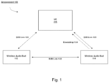
- Fig. 1 shows an example arrangement 100 of UE 110 and wireless audio buds 112, 114 according to various exemplary embodiments.
- the exemplary arrangement 100 includes a UE 110.
- the UE 110 may represent any type of electronic component that is capable of communicating with one or more wireless audio output devices.
- Specific examples of the UE 110 include, but are not limited to, mobile phones, tablet computers, desktop computers, smartphones, embedded devices, wearables, Internet of Things (IoT) devices, video game consoles, media players, entertainment devices, smart speakers, smart TVs, streaming devices, etc.
- IoT Internet of Things
- the terms "UE” and “source device” may be used interchangeably throughout this description.
- the UE 110 may communicate with a pair of wireless audio buds 112, 114 (e.g., ear buds, wireless headphones, etc.).
- wireless audio buds 112, 114 e.g., ear buds, wireless headphones, etc.
- any reference to wireless audio buds is merely provided for illustrative purposes.
- the exemplary embodiments may apply to scenarios that include any appropriate type of audio output device, including one or more wireless speakers and devices with one or more integrated speakers.
- the example arrangement 100 also illustrates various types of communication links and/or interactions that may occur when using the short-range communication protocol.
- a network of these connections may represent a PAN.
- the arrangement 100 shows a source-to-audio bud (S2B) link 120 between the UE 110 and the wireless audio bud 112 (primary bud).
- S2B source-to-audio bud
- B2B audio bud-to-audio bud
- the communication links 120, 122 may be Bluetooth connections or any other appropriate type of connection. Therefore, the UE 110 and the wireless audio buds 112, 114 may be equipped with an appropriate chipset to communicate using a short-range communication protocol.
- the wireless audio bud 114 may be enabled to eavesdrop 124 (or snoop) on data being exchanged on the S2B link 120. In some embodiments, the wireless audio bud 114 may establish a S2B link 125 with the UE 110. This additional S2B link 125 may be used instead of or in addition to the eavesdrop 124 and the B2B link 122.
- Communication links may be established using a manual approach, an automated approach or a combination thereof.
- the manual approach refers to a process in which user input at one or more of the devices triggers the initiation of a connection establishment procedure.
- the automated approach refers to a mechanism in which connection establishment is initiated without a user-supplied command, e.g., using sensor data, proximity detection, an automated trigger, and/or other operations.
- the arrangement 100 illustrates a possible network of short-range connections among the UE 110 and the wireless audio buds 112, 114.
- the UE 110 and the audio bud 112 have a primary/secondary relationship over the S2B link 120 where the UE 110 is in control and/or has priority over the audio bud 112.
- the UE 110 and the audio bud 114 may also have a primary/secondary relationship over the S2B link 125 where the UE 110 is in control and/or has priority over the audio bud 114.
- the audio bud 112 and the audio bud 114 may have a primary/secondary relationship over the B2B link 122 where the audio bud 112 is in control and/or has priority over the audio bud 114.
- devices connected via a short-range communication protocol e.g., S2B link 120, S2B link 125, B2B link 122 may have a mutual relationship where the devices share or negotiate certain responsibilities.
- a primary/secondary relationship between audio buds may be dynamic.
- the audio bud 112 may be set as the primary bud and the audio bud 114 may be set as the secondary bud.
- a predetermined condition may trigger the audio bud 114 to be set as the primary bud.
- the audio bud 114 may be set as the primary bud and the audio bud 112 may be set as the secondary bud.
- the pair of audio buds 112, 114 may switch roles any number of times.
- the wireless audio bud 112 will be referred to as the primary bud and the wireless audio bud 114 will be referred to as the secondary bud.
- Fig. 2 shows an example UE 110 according to various exemplary embodiments.
- the UE 110 will be described with regard to the arrangement 100 of Fig. 2 .
- the UE 110 may include a processor 205, a memory arrangement 210, a display device 215, an input/output (I/O) device 220, a transceiver 225 and other components 230.
- the other components 230 may include, for example, an audio input device, an audio output device, a power supply, a data acquisition device, ports to electrically connect the UE 110 to other electronic devices, etc.
- the processor 205 may be configured to execute a plurality of engines of the UE 110.
- the engines may include a packet management engine 235.
- the packet management engine 235 may be configured to perform operations related to processing microphone audio packets from both wireless audio buds 112,114 and voice accelerometer data, as will be described in greater detail below.
- the above referenced engine 235 being an application (e.g., a program) executed by the processor 205 is merely provided for illustrative purposes.
- the functionality associated with the engine 235 may also be represented as a separate incorporated component of the UE 110 or may be a modular component coupled to the UE 110, e.g., an integrated circuit with or without firmware.
- the integrated circuit may include input circuitry to receive signals and processing circuitry to process the signals and other information.
- the engines may also be embodied as one application or separate applications.
- the functionality described for the processor 205 is split among two or more processors such as a baseband processor and an applications processor.
- the exemplary embodiments may be implemented in any of these or other configurations of a UE.
- the memory arrangement 210 may be a hardware component configured to store data related to operations performed by the UE 110.
- the display device 215 may be a hardware component configured to show data to a user while the I/O device 220 may be a hardware component that enables the user to enter inputs.
- the display device 215 and the I/O device 220 may be separate components or integrated together such as a touchscreen.
- the transceiver 225 may represent one or more hardware components configured to perform operations related to wireless communication.
- the transceiver 225 may represent one or more radios configured to communicate with a cellular network, a PAN, a wireless local area network (WLAN), etc.
- the exemplary embodiments may include the UE 110 communicating with a first audio output device over a first frequency band and a second audio output device over a second different frequency band.
- the transceiver 225 may operate on a variety of different frequencies or channels (e.g., set of consecutive frequencies).
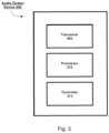
- Fig. 3 shows an example audio output device 300 according to various exemplary embodiments.
- the audio output device 300 may represent either or both of the audio buds 112, 114 shown in the arrangement 100.
- the device 300 may include a transceiver 305, a processor 310 and a controller 315.
- the device 300 may include other components (not shown) such as, but not limited to, a microphone, a memory, a battery and ports to electrically connect the device 300 to other electronic devices.
- the transceiver 305 may represent one or more hardware components configured to perform operations related to wireless communication.
- the transceiver 305 may represent one or more radios configured to communicate with a PAN or any other appropriate type of network.
- the transceiver 305 may enable a short-range connection to be established using frequencies or channels associated with the short-range connection (e.g., Bluetooth). In some embodiments, these frequencies may include the 2.4 GHz and 5 GHz bands. Accordingly, the transceiver 305 may operate on a variety of different frequencies or channels (e.g., set of consecutive frequencies).
- the processor 310 may be configured to execute a plurality of engines for the audio output device 300.
- the processor 310 may perform operations related to receiving connection information from a source device and joining an existing audio session.
- the processor 310 may be represented as a separate incorporated component of the audio output device 300 or may be a modular component coupled to the audio output device 300, e.g., an integrated circuit with or without firmware.
- the processor 310 may be a chip or integrated circuit compatible with the short-range communication protocol that includes input circuitry to receive signals and processing circuitry to process the signals and other information.
- the engines may also be embodied as one application or separate applications.
- the functionality described for the processor 310 is split among two or more processors such as a baseband processor and an applications processor.
- the transceiver 305 may also be configured to execute engines and/or operations for the audio output device 300.
- the controller 315 may be configured to control the communication functions of the transceiver 305 and/or the processor 310. In addition, the controller 315 may also control non-communication functions related to the other components such as the memory, the battery, etc. Accordingly, the controller 315 may perform operations associated with an applications processor.
- the exemplary embodiments may be implemented in any of these or other configurations of an audio output device.
- Fig. 4 shows an example method 400 of transmitting primary and secondary microphone audio data to a source device (e.g., UE 110) according to various exemplary embodiments.
- a source device e.g., UE 110
- a primary bud and a secondary bud may be references to a primary bud and a secondary bud.
- the exemplary embodiments are not limited to one of the wireless audio buds 112,114 being a primary bud and the other being a secondary bud.
- a short-range connection is established between a source device (e.g., UE 110) and a first audio output device (e.g., wireless audio bud 112).
- the short-range connection may be established using either a manual approach or an automated approach.
- the audio bud 112 may provide connection information directly to the audio bud 114. This connection information may facilitate the establishment of the B2B link 122, the eavesdrop 124 and/or the S2B link 125.
- the source device provides audio data to the first and second wireless audio output devices (wireless audio buds 112, 114).
- the primary bud e.g., wireless audio bud 112 receives the audio data from the source device over the S2B link 120.
- the secondary bud e.g., wireless audio bud 1142 may receive the audio data via the eavesdrop link 124.
- the audio data may be any type of payload data that may provide the basis for generating audio output. To provide some examples, the audio data may be part of a voice call or a data call.
- the wireless audio output device determines whether both audio output devices received the audio packets from the source device. If one of the audio output devices (e.g., wireless audio bud 114) did not receive the audio packets from the source device successfully, then, at 420, the other one of the audio output devices (e.g., wireless audio bud 112) may transmit the lost audio packet to the device that did not receive it successfully. This lost packet transmission may occur over the B2B link 122. In other embodiments, the source device may retransmit the audio packet(s) that were not received successfully by both audio output devices.
- the audio output devices e.g., wireless audio bud 112
- the primary bud e.g., wireless audio bud 112 receives microphone audio data from the secondary bud (e.g., wireless audio bud 114).
- the secondary bud may transmit its microphone audio data to the primary bud over the B2B link 122.
- This B2B link 122 is the same link referenced above for the lost packets. Thus, the same B2B link may be used to deliver the lost packets and the microphone audio data.
- the primary bud (e.g., wireless audio bud 112) transmits its microphone audio data and the secondary microphone audio data received from the secondary bud to the source device.
- the primary bud may also transmit data from a voice accelerometer to the source device.
- the voice accelerometer data is from the primary bud's accelerometer.
- the voice accelerometer data is alternatively from the secondary bud's accelerometer and is sent to the primary bud along with the secondary bud's microphone audio data at 425.
- the source device may use the accelerometer data to monitor and/or process user health-related parameters.
- the operations 410-430 may be performed for each audio data packet or for a set of one or more audio data packets provided by the source device.
- Fig. 5 shows a diagram illustrating an example of an extended synchronous connection oriented (eSCO) data traffic between a UE 110 and an audio output device (e.g., wireless ear buds 112,114) according to various exemplary embodiments.
- the UE 110 transmits audio data packets to the audio output device(s) in UE audio slot 502. If the UE transmission fails, the UE 110 may retransmit the audio data in the UE audio retransmission slot 502a.
- the primary bud e.g., wireless ear bud 112 transmits microphone audio data packets (both the primary and secondary microphone audio data) as well as any voice accelerometer data packets in the audio output device audio data slot 504. If the audio output device audio data transmission fails, then the output device may retransmit the audio data in the audio output device audio retransmission slot 504a.
- the eSCO data traffic includes B2B slots 516 in which the secondary bud (e.g., wireless ear bud 114) transmits its microphone audio data 506 to the primary bud.
- the B2B slots may also be referred to as peer-to-peer slots.
- the B2B slots 516 are used when one audio output device needs to transmit source audio to the other audio output device that did not successfully receive the source audio. However, because this happens rarely, the secondary microphone audio can be transmitted in the B2B slots 516 to advantageously save bandwidth.
- this source audio transmission can occur over the B2B slots 516 instead of the transmission of the secondary microphone audio.
- the secondary bud may continue to transmit the secondary microphone audio data in the next instance of the B2B slots (the next interval).
- Fig. 6 shows a diagram illustrating an example method of composing consolidated data packets for eSCO transmissions according to various exemplary embodiments.
- Fig. 6 shows primary mic sampling, secondary mic sampling, packet consolidation and eSCO traffic on the same time axis 601.
- the primary microphone e.g., wireless ear bud 112 microphone
- the secondary microphone e.g., wireless ear bud 114 microphone
- the sampling of the primary and secondary microphones is synchronized based on eSCO timing.
- the timing of the sampling corresponds to the duration between the eSCO traffic.
- the timing of the operations and traffic shown Fig. 6 may occur with any appropriate timing.
- the first interval of eSCO traffic includes source device audio packets 610, output device audio packets 612, and secondary bud audio packets 602b. While the plural "packets" is being used in this example, it is possible that a singular "packet” is included for one or more of the transmissions in the interval.
- the source device audio packets 610 may be transmitted by the source device over the S2B link 120 to the primary bud (e.g., wireless ear bud 112) in the UE audio slot of the first interval.
- the output device audio packets 612 in the audio output device audio data slot of the first interval of eSCO traffic may not include any payload data.
- the primary bud may wait to receive the secondary bud audio packets 602b before sending the output device audio packets to the source device in a subsequent interval.
- the secondary bud audio packets 602b are transmitted to the primary bud in the B2B slots of an eSCO transmission interval.
- the primary bud After receiving the secondary bud audio packets 602b, the primary bud performs a packet consolidation for the primary and secondary bud audio packets 602a,b.
- the source audio packets are again sent from the source device to the primary bud.
- the primary bud transmits the consolidated packet having the primary and secondary audio data (microphone audio) to the source device.
- the second interval also includes the secondary bud's subsequent audio packets 604b in the B2B slots of the eSCO interval.
- the consolidated audio packet 700 may include a packet header 702, the primary audio data 704, the secondary audio data 706, and voice accelerometer data 708.
- the packet header 702 may include information that indicates what type of data is included in the payload of the consolidated audio packet 700, e.g., each consolidated audio packet 700 is not required to include all of the primary audio data 704, the secondary audio data 706, and the voice accelerometer data 708.
- personally identifiable information should follow privacy policies and practices that are generally recognized as meeting or exceeding industry or governmental requirements for maintaining the privacy of users.
- personally identifiable information data should be managed and handled so as to minimize risks of unintentional or unauthorized access or use, and the nature of authorized use should be clearly indicated to users.
Landscapes
- Engineering & Computer Science (AREA)
- Signal Processing (AREA)
- Computer Networks & Wireless Communication (AREA)
- Physics & Mathematics (AREA)
- Acoustics & Sound (AREA)
- Multimedia (AREA)
- Circuit For Audible Band Transducer (AREA)
- Mobile Radio Communication Systems (AREA)
Claims (10)
- Verfahren, das von einer ersten drahtlosen Audioausgabevorrichtung (112) durchgeführt wird, umfassend:Herstellen (405) einer Kommunikationsverbindung zu einer Quellvorrichtung (110) unter Verwendung eines drahtlosen Kommunikationsprotokolls mit kurzer Reichweite (120);Empfangen (410) Quellaudiodaten von der Quellvorrichtung;Empfangen (425) von sekundären Audiodaten von einer zweiten drahtlosen Audioausgabevorrichtung (114) über eine Audio-Bud-to-Audio-Bud-, B2B-, Verbindung (122);Kombinieren primären Audiodaten von der ersten drahtlosen Audioausgabevorrichtung mit den sekundären Audiodaten zu einem konsolidierten Audiopaket (700); undÜbertragen (430) des konsolidierten Audiopakets an die Quellvorrichtung,wobei die erste drahtlose Audioausgabevorrichtung ein primärer drahtloser Audio-Bud (112) ist und die zweite drahtlose Audioausgabevorrichtung ein sekundärer drahtloser Audio-Bud (114) ist;und das Verfahren dadurch gekennzeichnet ist, dass das konsolidierte Audiopaket ferner Beschleunigungsmesserdaten von einem Sprachbeschleunigungsmesser von einer der ersten drahtlosen Audioausgabevorrichtung oder der zweiten drahtlosen Audioausgabevorrichtung beinhaltet.
- Verfahren nach Anspruch 1, wobei die Beschleunigungsmesserdaten physiologische Daten umfassen, die einem Benutzer der ersten und zweiten drahtlosen Audioausgabevorrichtung zugeordnet sind.
- Verfahren nach einem der Ansprüche 1 oder 2, wobei die sekundären Audiodaten von der zweiten drahtlosen Audioausgabevorrichtung in einem Peer-to-Peer-Slot eines erweiterten synchronen verbindungsorientierten, eSCO-, Datenverkehrsintervalls empfangen werden.
- Verfahren nach einem der vorhergehenden Ansprüche, wobei die primären Audiodaten erstes Mikrofonaudio von einem ersten Mikrofon der ersten drahtlosen Audioausgabevorrichtung umfassen und die sekundären Audiodaten zweites Mikrofonaudio von einem zweiten Mikrofon der zweiten drahtlosen Audioausgabevorrichtung umfassen.
- Erste drahtlose Audioausgabevorrichtung (112), umfassend: einen Sendeempfänger, der konfiguriert ist, um mit einer Quellvorrichtung (110) zu kommunizieren;
einen Prozessor, der kommunikativ mit dem Sendeempfänger gekoppelt und konfiguriert ist, um Operationen durchzuführen, umfassend:Herstellen (405) einer Kommunikationsverbindung mit der Quellvorrichtung (110) unter Verwendung eines drahtlosen Kommunikationsprotokolls mit kurzer Reichweite (120);Empfangen (410) Quellaudiodaten von der Quellvorrichtung;Empfangen (425) von sekundären Audiodaten von einer zweiten drahtlosen Audioausgabevorrichtung (114) über eine Audio-Bud-to-Audio-Bud-, B2B-, Verbindung (122);Kombinieren primären Audiodaten von der ersten drahtlosen Audioausgabevorrichtung mit den sekundären Audiodaten, um ein konsolidiertes Audiopaket (700) zu erzeugen; undÜbertragen (430) des konsolidierten Audiopakets an die Quellvorrichtung,wobei die erste drahtlose Audioausgabevorrichtung ein primärer drahtloser Audio-Bud (112) ist und die zweite drahtlose Audioausgabevorrichtung ein sekundärer drahtloser Audio-Bud (114) ist;und die erste drahtlose Audioausgabevorrichtung dadurch gekennzeichnet ist, dass das konsolidierte Audiopaket ferner Beschleunigungsmesserdaten von einem Sprachbeschleunigungsmesser von einer der ersten drahtlosen Audioausgabevorrichtung oder der zweiten drahtlosen Audioausgabevorrichtung beinhaltet. - Erste drahtlose Audioausgabevorrichtung nach Anspruch 5, wobei der Sprachbeschleunigungsmesser konfiguriert ist, um Beschleunigungsmesserdaten zu sammeln, die einem Benutzer von einer der ersten drahtlosen Audioausgabevorrichtung oder der zweiten drahtlosen Audioausgabevorrichtung zugeordnet sind.
- Erste drahtlose Audioausgabevorrichtung nach Anspruch 6, wobei die Beschleunigungsmesserdaten physiologische Daten umfassen, die dem Benutzer zugeordnet sind.
- Erste drahtlose Audioausgabevorrichtung nach einem der Ansprüche 5 bis 7, wobei die sekundären Audiodaten von der zweiten drahtlosen Audioausgabevorrichtung in einem Peer-to-Peer-Slot eines erweiterten synchronen verbindungsorientierten, eSCO-, Datenverkehrsintervalls empfangen werden.
- Erste drahtlose Audioausgabevorrichtung nach einem der Ansprüche 5 bis 8, ferner umfassend:
ein Mikrofon, das konfiguriert ist, um die primären Audiodaten zu sammeln. - Erste drahtlose Audioausgabevorrichtung nach Anspruch 9, wobei die sekundären Audiodaten Mikrofonaudio umfassen, das von einem Mikrofon der zweiten drahtlosen Audioausgabevorrichtung gesammelt wird.
Priority Applications (1)
| Application Number | Priority Date | Filing Date | Title |
|---|---|---|---|
| EP24190110.7A EP4425963A3 (de) | 2021-09-24 | 2022-09-15 | Übertragung von mikrofonaudio von zwei oder mehr audioausgabevorrichtungen an eine quellenvorrichtung |
Applications Claiming Priority (1)
| Application Number | Priority Date | Filing Date | Title |
|---|---|---|---|
| US17/448,758 US11665473B2 (en) | 2021-09-24 | 2021-09-24 | Transmitting microphone audio from two or more audio output devices to a source device |
Related Child Applications (2)
| Application Number | Title | Priority Date | Filing Date |
|---|---|---|---|
| EP24190110.7A Division EP4425963A3 (de) | 2021-09-24 | 2022-09-15 | Übertragung von mikrofonaudio von zwei oder mehr audioausgabevorrichtungen an eine quellenvorrichtung |
| EP24190110.7A Division-Into EP4425963A3 (de) | 2021-09-24 | 2022-09-15 | Übertragung von mikrofonaudio von zwei oder mehr audioausgabevorrichtungen an eine quellenvorrichtung |
Publications (2)
| Publication Number | Publication Date |
|---|---|
| EP4156713A1 EP4156713A1 (de) | 2023-03-29 |
| EP4156713B1 true EP4156713B1 (de) | 2025-01-15 |
Family
ID=83594444
Family Applications (2)
| Application Number | Title | Priority Date | Filing Date |
|---|---|---|---|
| EP24190110.7A Pending EP4425963A3 (de) | 2021-09-24 | 2022-09-15 | Übertragung von mikrofonaudio von zwei oder mehr audioausgabevorrichtungen an eine quellenvorrichtung |
| EP22195966.1A Active EP4156713B1 (de) | 2021-09-24 | 2022-09-15 | Übertragung von mikrofonaudio von zwei oder mehr audioausgabevorrichtungen an eine quellenvorrichtung |
Family Applications Before (1)
| Application Number | Title | Priority Date | Filing Date |
|---|---|---|---|
| EP24190110.7A Pending EP4425963A3 (de) | 2021-09-24 | 2022-09-15 | Übertragung von mikrofonaudio von zwei oder mehr audioausgabevorrichtungen an eine quellenvorrichtung |
Country Status (3)
| Country | Link |
|---|---|
| US (1) | US11665473B2 (de) |
| EP (2) | EP4425963A3 (de) |
| CN (1) | CN115866488A (de) |
Family Cites Families (10)
| Publication number | Priority date | Publication date | Assignee | Title |
|---|---|---|---|---|
| US9313572B2 (en) | 2012-09-28 | 2016-04-12 | Apple Inc. | System and method of detecting a user's voice activity using an accelerometer |
| US10499139B2 (en) | 2017-03-20 | 2019-12-03 | Bose Corporation | Audio signal processing for noise reduction |
| US10410634B2 (en) | 2017-05-18 | 2019-09-10 | Smartear, Inc. | Ear-borne audio device conversation recording and compressed data transmission |
| US20190104424A1 (en) | 2017-09-29 | 2019-04-04 | Apple Inc. | Ultra-low latency audio over bluetooth |
| KR20200120660A (ko) | 2018-02-13 | 2020-10-21 | 마인드마익스 인코포레이티드 | 초저주파 음파 바이오센서 시스템 및 방법 |
| TWI668972B (zh) * | 2018-02-13 | 2019-08-11 | 絡達科技股份有限公司 | 無線音訊輸出裝置 |
| US10419853B2 (en) * | 2018-02-21 | 2019-09-17 | Apple Inc. | Binaural audio capture using untethered wireless headset |
| WO2021137569A1 (en) * | 2019-12-31 | 2021-07-08 | Samsung Electronics Co., Ltd. | Method for transceiving data in bluetooth network environment and electronic device thereof |
| US10944154B1 (en) | 2020-09-24 | 2021-03-09 | Bestechnic (Shanghai) Co., Ltd. | Wireless audio system and method for wirelessly communicating audio information using the same |
| CN112867138B (zh) * | 2020-10-13 | 2023-02-24 | 恒玄科技(上海)股份有限公司 | 音频系统及无线耳机对 |
-
2021
- 2021-09-24 US US17/448,758 patent/US11665473B2/en active Active
-
2022
- 2022-09-15 EP EP24190110.7A patent/EP4425963A3/de active Pending
- 2022-09-15 EP EP22195966.1A patent/EP4156713B1/de active Active
- 2022-09-15 CN CN202211121045.5A patent/CN115866488A/zh active Pending
Also Published As
| Publication number | Publication date |
|---|---|
| EP4425963A3 (de) | 2024-10-09 |
| EP4425963A2 (de) | 2024-09-04 |
| US11665473B2 (en) | 2023-05-30 |
| CN115866488A (zh) | 2023-03-28 |
| EP4156713A1 (de) | 2023-03-29 |
| US20230096843A1 (en) | 2023-03-30 |
Similar Documents
| Publication | Publication Date | Title |
|---|---|---|
| CN112868244B (zh) | 一种点对多点的数据传输方法及设备 | |
| US8983384B2 (en) | Apparatus and method for extending Bluetooth device range | |
| CN106911857B (zh) | 一种语音数据交互方法及装置 | |
| CN109995479A (zh) | 一种音频数据通信方法、系统及音频通信设备 | |
| CN102331727B (zh) | 一种蓝牙媒体播放控制方法和相关装置 | |
| CN112188344B (zh) | Tws耳机及其控制方法 | |
| US20250106920A1 (en) | Variable physical layer symbol rate for a wireless communication link | |
| EP4093070A1 (de) | Audioübertragungsverfahren und elektronische vorrichtung | |
| US12627960B2 (en) | Physical layer improvements for short range wireless communications | |
| EP4156713A1 (de) | Übertragung von mikrofonaudio von zwei oder mehr audioausgabevorrichtungen an eine quellenvorrichtung | |
| EP4009699B1 (de) | Datensendeverfahren und benutzerausrüstung | |
| US20210218505A1 (en) | Data transmission method, terminal, and network device | |
| US10015652B2 (en) | Near-field wireless communication equipment, and near-field wireless communication method | |
| CN113472379B (zh) | 一种对讲通信方法、耳机盒、耳机及存储介质 | |
| CN115175159B (zh) | 一种蓝牙耳机播放方法及设备 | |
| KR102044523B1 (ko) | 근거리 무선 통신 장치 및 방법 | |
| EP3624356B1 (de) | Drahtloses headset und signalübertragungsverfahren dafür | |
| EP4266711A1 (de) | Verfahren und system zur drahtlosen kommunikation | |
| CN115604689B (zh) | 用于加入现有音频会话的方法和设备 | |
| US20260095733A1 (en) | Cross-Device Guest Pairing and Sensor Data Routing | |
| EP4123642B1 (de) | Audioübertragungsverfahren und elektronische vorrichtung | |
| WO2024081111A1 (en) | Physical layer improvements for short range wireless communications | |
| US20230100388A1 (en) | Feedback-Based Frequency Hopping | |
| EP4578201A1 (de) | Systeme und verfahren zur verbesserung der sprachanrufqualität und vorrichtungslatenz | |
| HK40066273A (en) | Data sending method and user equipment |
Legal Events
| Date | Code | Title | Description |
|---|---|---|---|
| PUAI | Public reference made under article 153(3) epc to a published international application that has entered the european phase |
Free format text: ORIGINAL CODE: 0009012 |
|
| STAA | Information on the status of an ep patent application or granted ep patent |
Free format text: STATUS: REQUEST FOR EXAMINATION WAS MADE |
|
| 17P | Request for examination filed |
Effective date: 20220915 |
|
| AK | Designated contracting states |
Kind code of ref document: A1 Designated state(s): AL AT BE BG CH CY CZ DE DK EE ES FI FR GB GR HR HU IE IS IT LI LT LU LV MC MK MT NL NO PL PT RO RS SE SI SK SM TR |
|
| GRAP | Despatch of communication of intention to grant a patent |
Free format text: ORIGINAL CODE: EPIDOSNIGR1 |
|
| STAA | Information on the status of an ep patent application or granted ep patent |
Free format text: STATUS: GRANT OF PATENT IS INTENDED |
|
| RIC1 | Information provided on ipc code assigned before grant |
Ipc: H04R 3/12 20060101ALI20240229BHEP Ipc: H04R 1/10 20060101ALI20240229BHEP Ipc: H04L 65/80 20220101ALI20240229BHEP Ipc: H04W 4/80 20180101ALI20240229BHEP Ipc: H04R 5/033 20060101AFI20240229BHEP |
|
| INTG | Intention to grant announced |
Effective date: 20240327 |
|
| GRAJ | Information related to disapproval of communication of intention to grant by the applicant or resumption of examination proceedings by the epo deleted |
Free format text: ORIGINAL CODE: EPIDOSDIGR1 |
|
| STAA | Information on the status of an ep patent application or granted ep patent |
Free format text: STATUS: REQUEST FOR EXAMINATION WAS MADE |
|
| P01 | Opt-out of the competence of the unified patent court (upc) registered |
Free format text: CASE NUMBER: APP_36194/2024 Effective date: 20240617 |
|
| GRAP | Despatch of communication of intention to grant a patent |
Free format text: ORIGINAL CODE: EPIDOSNIGR1 |
|
| STAA | Information on the status of an ep patent application or granted ep patent |
Free format text: STATUS: GRANT OF PATENT IS INTENDED |
|
| INTC | Intention to grant announced (deleted) | ||
| INTG | Intention to grant announced |
Effective date: 20240801 |
|
| GRAS | Grant fee paid |
Free format text: ORIGINAL CODE: EPIDOSNIGR3 |
|
| GRAA | (expected) grant |
Free format text: ORIGINAL CODE: 0009210 |
|
| STAA | Information on the status of an ep patent application or granted ep patent |
Free format text: STATUS: THE PATENT HAS BEEN GRANTED |
|
| AK | Designated contracting states |
Kind code of ref document: B1 Designated state(s): AL AT BE BG CH CY CZ DE DK EE ES FI FR GB GR HR HU IE IS IT LI LT LU LV MC MK MT NL NO PL PT RO RS SE SI SK SM TR |
|
| REG | Reference to a national code |
Ref country code: CH Ref legal event code: EP Ref country code: GB Ref legal event code: FG4D |
|
| REG | Reference to a national code |
Ref country code: DE Ref legal event code: R096 Ref document number: 602022009533 Country of ref document: DE |
|
| REG | Reference to a national code |
Ref country code: NL Ref legal event code: FP |
|
| REG | Reference to a national code |
Ref country code: IE Ref legal event code: FG4D |
|
| PG25 | Lapsed in a contracting state [announced via postgrant information from national office to epo] |
Ref country code: RS Free format text: LAPSE BECAUSE OF FAILURE TO SUBMIT A TRANSLATION OF THE DESCRIPTION OR TO PAY THE FEE WITHIN THE PRESCRIBED TIME-LIMIT Effective date: 20250415 |
|
| PG25 | Lapsed in a contracting state [announced via postgrant information from national office to epo] |
Ref country code: FI Free format text: LAPSE BECAUSE OF FAILURE TO SUBMIT A TRANSLATION OF THE DESCRIPTION OR TO PAY THE FEE WITHIN THE PRESCRIBED TIME-LIMIT Effective date: 20250115 |
|
| PG25 | Lapsed in a contracting state [announced via postgrant information from national office to epo] |
Ref country code: PL Free format text: LAPSE BECAUSE OF FAILURE TO SUBMIT A TRANSLATION OF THE DESCRIPTION OR TO PAY THE FEE WITHIN THE PRESCRIBED TIME-LIMIT Effective date: 20250115 |
|
| PG25 | Lapsed in a contracting state [announced via postgrant information from national office to epo] |
Ref country code: ES Free format text: LAPSE BECAUSE OF FAILURE TO SUBMIT A TRANSLATION OF THE DESCRIPTION OR TO PAY THE FEE WITHIN THE PRESCRIBED TIME-LIMIT Effective date: 20250115 |
|
| REG | Reference to a national code |
Ref country code: LT Ref legal event code: MG9D |
|
| PG25 | Lapsed in a contracting state [announced via postgrant information from national office to epo] |
Ref country code: NO Free format text: LAPSE BECAUSE OF FAILURE TO SUBMIT A TRANSLATION OF THE DESCRIPTION OR TO PAY THE FEE WITHIN THE PRESCRIBED TIME-LIMIT Effective date: 20250415 Ref country code: IS Free format text: LAPSE BECAUSE OF FAILURE TO SUBMIT A TRANSLATION OF THE DESCRIPTION OR TO PAY THE FEE WITHIN THE PRESCRIBED TIME-LIMIT Effective date: 20250515 |
|
| REG | Reference to a national code |
Ref country code: AT Ref legal event code: MK05 Ref document number: 1760601 Country of ref document: AT Kind code of ref document: T Effective date: 20250115 |
|
| PG25 | Lapsed in a contracting state [announced via postgrant information from national office to epo] |
Ref country code: HR Free format text: LAPSE BECAUSE OF FAILURE TO SUBMIT A TRANSLATION OF THE DESCRIPTION OR TO PAY THE FEE WITHIN THE PRESCRIBED TIME-LIMIT Effective date: 20250115 |
|
| PG25 | Lapsed in a contracting state [announced via postgrant information from national office to epo] |
Ref country code: LV Free format text: LAPSE BECAUSE OF FAILURE TO SUBMIT A TRANSLATION OF THE DESCRIPTION OR TO PAY THE FEE WITHIN THE PRESCRIBED TIME-LIMIT Effective date: 20250115 Ref country code: PT Free format text: LAPSE BECAUSE OF FAILURE TO SUBMIT A TRANSLATION OF THE DESCRIPTION OR TO PAY THE FEE WITHIN THE PRESCRIBED TIME-LIMIT Effective date: 20250515 |
|
| PG25 | Lapsed in a contracting state [announced via postgrant information from national office to epo] |
Ref country code: BG Free format text: LAPSE BECAUSE OF FAILURE TO SUBMIT A TRANSLATION OF THE DESCRIPTION OR TO PAY THE FEE WITHIN THE PRESCRIBED TIME-LIMIT Effective date: 20250115 Ref country code: GR Free format text: LAPSE BECAUSE OF FAILURE TO SUBMIT A TRANSLATION OF THE DESCRIPTION OR TO PAY THE FEE WITHIN THE PRESCRIBED TIME-LIMIT Effective date: 20250416 |
|
| PG25 | Lapsed in a contracting state [announced via postgrant information from national office to epo] |
Ref country code: AT Free format text: LAPSE BECAUSE OF FAILURE TO SUBMIT A TRANSLATION OF THE DESCRIPTION OR TO PAY THE FEE WITHIN THE PRESCRIBED TIME-LIMIT Effective date: 20250115 |
|
| PGFP | Annual fee paid to national office [announced via postgrant information from national office to epo] |
Ref country code: NL Payment date: 20250704 Year of fee payment: 4 |
|
| PG25 | Lapsed in a contracting state [announced via postgrant information from national office to epo] |
Ref country code: SE Free format text: LAPSE BECAUSE OF FAILURE TO SUBMIT A TRANSLATION OF THE DESCRIPTION OR TO PAY THE FEE WITHIN THE PRESCRIBED TIME-LIMIT Effective date: 20250115 |
|
| PG25 | Lapsed in a contracting state [announced via postgrant information from national office to epo] |
Ref country code: SM Free format text: LAPSE BECAUSE OF FAILURE TO SUBMIT A TRANSLATION OF THE DESCRIPTION OR TO PAY THE FEE WITHIN THE PRESCRIBED TIME-LIMIT Effective date: 20250115 |
|
| PG25 | Lapsed in a contracting state [announced via postgrant information from national office to epo] |
Ref country code: DK Free format text: LAPSE BECAUSE OF FAILURE TO SUBMIT A TRANSLATION OF THE DESCRIPTION OR TO PAY THE FEE WITHIN THE PRESCRIBED TIME-LIMIT Effective date: 20250115 |
|
| PGFP | Annual fee paid to national office [announced via postgrant information from national office to epo] |
Ref country code: DE Payment date: 20250702 Year of fee payment: 4 |
|
| PG25 | Lapsed in a contracting state [announced via postgrant information from national office to epo] |
Ref country code: IT Free format text: LAPSE BECAUSE OF FAILURE TO SUBMIT A TRANSLATION OF THE DESCRIPTION OR TO PAY THE FEE WITHIN THE PRESCRIBED TIME-LIMIT Effective date: 20250115 |
|
| REG | Reference to a national code |
Ref country code: DE Ref legal event code: R097 Ref document number: 602022009533 Country of ref document: DE |
|
| PG25 | Lapsed in a contracting state [announced via postgrant information from national office to epo] |
Ref country code: EE Free format text: LAPSE BECAUSE OF FAILURE TO SUBMIT A TRANSLATION OF THE DESCRIPTION OR TO PAY THE FEE WITHIN THE PRESCRIBED TIME-LIMIT Effective date: 20250115 Ref country code: CZ Free format text: LAPSE BECAUSE OF FAILURE TO SUBMIT A TRANSLATION OF THE DESCRIPTION OR TO PAY THE FEE WITHIN THE PRESCRIBED TIME-LIMIT Effective date: 20250115 |
|
| PG25 | Lapsed in a contracting state [announced via postgrant information from national office to epo] |
Ref country code: RO Free format text: LAPSE BECAUSE OF FAILURE TO SUBMIT A TRANSLATION OF THE DESCRIPTION OR TO PAY THE FEE WITHIN THE PRESCRIBED TIME-LIMIT Effective date: 20250115 |
|
| PG25 | Lapsed in a contracting state [announced via postgrant information from national office to epo] |
Ref country code: SK Free format text: LAPSE BECAUSE OF FAILURE TO SUBMIT A TRANSLATION OF THE DESCRIPTION OR TO PAY THE FEE WITHIN THE PRESCRIBED TIME-LIMIT Effective date: 20250115 |
|
| PLBE | No opposition filed within time limit |
Free format text: ORIGINAL CODE: 0009261 |
|
| STAA | Information on the status of an ep patent application or granted ep patent |
Free format text: STATUS: NO OPPOSITION FILED WITHIN TIME LIMIT |
|
| REG | Reference to a national code |
Ref country code: CH Ref legal event code: L10 Free format text: ST27 STATUS EVENT CODE: U-0-0-L10-L00 (AS PROVIDED BY THE NATIONAL OFFICE) Effective date: 20251126 |
|
| 26N | No opposition filed |
Effective date: 20251016 |
|
| REG | Reference to a national code |
Ref country code: CH Ref legal event code: H13 Free format text: ST27 STATUS EVENT CODE: U-0-0-H10-H13 (AS PROVIDED BY THE NATIONAL OFFICE) Effective date: 20260504 |