EP4009699B1 - Datensendeverfahren und benutzerausrüstung - Google Patents
Datensendeverfahren und benutzerausrüstung Download PDFInfo
- Publication number
- EP4009699B1 EP4009699B1 EP20848227.3A EP20848227A EP4009699B1 EP 4009699 B1 EP4009699 B1 EP 4009699B1 EP 20848227 A EP20848227 A EP 20848227A EP 4009699 B1 EP4009699 B1 EP 4009699B1
- Authority
- EP
- European Patent Office
- Prior art keywords
- path
- data
- uplink data
- target
- transmitting
- Prior art date
- Legal status (The legal status is an assumption and is not a legal conclusion. Google has not performed a legal analysis and makes no representation as to the accuracy of the status listed.)
- Active
Links
Images

Classifications
-
- H—ELECTRICITY
- H04—ELECTRIC COMMUNICATION TECHNIQUE
- H04W—WIRELESS COMMUNICATION NETWORKS
- H04W36/00—Hand-off or reselection arrangements
- H04W36/0005—Control or signalling for completing the hand-off
- H04W36/0055—Transmission or use of information for re-establishing the radio link
- H04W36/0077—Transmission or use of information for re-establishing the radio link of access information of target access point
-
- H—ELECTRICITY
- H04—ELECTRIC COMMUNICATION TECHNIQUE
- H04L—TRANSMISSION OF DIGITAL INFORMATION, e.g. TELEGRAPHIC COMMUNICATION
- H04L5/00—Arrangements affording multiple use of the transmission path
- H04L5/0091—Signalling for the administration of the divided path, e.g. signalling of configuration information
- H04L5/0096—Indication of changes in allocation
- H04L5/0098—Signalling of the activation or deactivation of component carriers, subcarriers or frequency bands
-
- H—ELECTRICITY
- H04—ELECTRIC COMMUNICATION TECHNIQUE
- H04W—WIRELESS COMMUNICATION NETWORKS
- H04W28/00—Network traffic management; Network resource management
- H04W28/02—Traffic management, e.g. flow control or congestion control
- H04W28/08—Load balancing or load distribution
- H04W28/0858—Load balancing or load distribution among entities in the uplink
-
- H—ELECTRICITY
- H04—ELECTRIC COMMUNICATION TECHNIQUE
- H04W—WIRELESS COMMUNICATION NETWORKS
- H04W28/00—Network traffic management; Network resource management
- H04W28/02—Traffic management, e.g. flow control or congestion control
- H04W28/08—Load balancing or load distribution
- H04W28/086—Load balancing or load distribution among access entities
- H04W28/0861—Load balancing or load distribution among access entities between base stations
-
- H—ELECTRICITY
- H04—ELECTRIC COMMUNICATION TECHNIQUE
- H04W—WIRELESS COMMUNICATION NETWORKS
- H04W28/00—Network traffic management; Network resource management
- H04W28/02—Traffic management, e.g. flow control or congestion control
- H04W28/08—Load balancing or load distribution
- H04W28/09—Management thereof
-
- H—ELECTRICITY
- H04—ELECTRIC COMMUNICATION TECHNIQUE
- H04W—WIRELESS COMMUNICATION NETWORKS
- H04W36/00—Hand-off or reselection arrangements
- H04W36/0005—Control or signalling for completing the hand-off
- H04W36/0011—Control or signalling for completing the hand-off for data sessions of end-to-end connection
- H04W36/0027—Control or signalling for completing the hand-off for data sessions of end-to-end connection for a plurality of data sessions of end-to-end connections, e.g. multi-call or multi-bearer end-to-end data connections
-
- H—ELECTRICITY
- H04—ELECTRIC COMMUNICATION TECHNIQUE
- H04W—WIRELESS COMMUNICATION NETWORKS
- H04W36/00—Hand-off or reselection arrangements
- H04W36/02—Buffering or recovering information during reselection ; Modification of the traffic flow during hand-off
-
- H—ELECTRICITY
- H04—ELECTRIC COMMUNICATION TECHNIQUE
- H04W—WIRELESS COMMUNICATION NETWORKS
- H04W72/00—Local resource management
- H04W72/20—Control channels or signalling for resource management
- H04W72/23—Control channels or signalling for resource management in the downlink direction of a wireless link, i.e. towards a terminal
-
- H—ELECTRICITY
- H04—ELECTRIC COMMUNICATION TECHNIQUE
- H04W—WIRELESS COMMUNICATION NETWORKS
- H04W76/00—Connection management
- H04W76/10—Connection setup
- H04W76/15—Setup of multiple wireless link connections
-
- H—ELECTRICITY
- H04—ELECTRIC COMMUNICATION TECHNIQUE
- H04W—WIRELESS COMMUNICATION NETWORKS
- H04W76/00—Connection management
- H04W76/10—Connection setup
- H04W76/19—Connection re-establishment
-
- H—ELECTRICITY
- H04—ELECTRIC COMMUNICATION TECHNIQUE
- H04W—WIRELESS COMMUNICATION NETWORKS
- H04W76/00—Connection management
- H04W76/20—Manipulation of established connections
-
- H—ELECTRICITY
- H04—ELECTRIC COMMUNICATION TECHNIQUE
- H04W—WIRELESS COMMUNICATION NETWORKS
- H04W76/00—Connection management
- H04W76/30—Connection release
-
- H—ELECTRICITY
- H04—ELECTRIC COMMUNICATION TECHNIQUE
- H04W—WIRELESS COMMUNICATION NETWORKS
- H04W36/00—Hand-off or reselection arrangements
- H04W36/0005—Control or signalling for completing the hand-off
- H04W36/0055—Transmission or use of information for re-establishing the radio link
- H04W36/0069—Transmission or use of information for re-establishing the radio link in case of dual connectivity, e.g. decoupled uplink/downlink
- H04W36/00692—Transmission or use of information for re-establishing the radio link in case of dual connectivity, e.g. decoupled uplink/downlink using simultaneous multiple data streams, e.g. cooperative multipoint [CoMP], carrier aggregation [CA] or multiple input multiple output [MIMO]
-
- H—ELECTRICITY
- H04—ELECTRIC COMMUNICATION TECHNIQUE
- H04W—WIRELESS COMMUNICATION NETWORKS
- H04W36/00—Hand-off or reselection arrangements
- H04W36/24—Reselection being triggered by specific parameters
- H04W36/32—Reselection being triggered by specific parameters by location or mobility data, e.g. speed data
- H04W36/324—Reselection being triggered by specific parameters by location or mobility data, e.g. speed data by mobility data, e.g. speed data
Definitions
- This disclosure relates to the field of communications technologies, and in particular, to a data transmission method and user equipment.
- Dual-connectivity means that UE may establish a connection with each of two cell groups (that is, a master cell group (MCG) and a secondary cell group (SCG)) at the same time.
- MCG includes at least a primary cell (PCell), and may further include at least one secondary cell (SCell); and the SCG includes at least a primary secondary cell (PSCell), and may further include at least one SCell.
- PCell primary cell
- SCell secondary cell
- PSCell primary secondary cell
- Both the PCell and the PSCell may also be referred to as a SpCell (Special Cell).
- the UE may establish a connection with both a source cell and a target cell at the same time, and then the UE releases the connection with the source cell, and only maintains the connection with the target cell.
- SCG change secondary cell group change
- the UE may only be capable of transmitting uplink data on one path at a same moment.
- EP 2389029A1 relates to a method for managing uplink carrier frequencies.
- EP 3328119A1 relates to a communication method and system for converging a 5 th generation communication system for supporting higher data rates beyond a 4 th generation system with a technology for Internet of Things (IoT).
- IoT Internet of Things
- Embodiments of this disclosure provide a data transmission method and user equipment, to resolve a problem in a dual-connectivity mobility management procedure that an uplink data transmission is interrupted or delayed.
- the present invention provides a data transmission method, applied to user equipment UE according to claim 1 and further detailed in the dependent claims referring back to this claim.
- a corresponding User equipment UE and a corresponding computer-readable storage medium are provided in claims 12 and 14.
- an embodiment of this disclosure provides a data transmission method, applied to UE, and the method includes: performing a target operation on first uplink data according to first information in a dual-connectivity mobility management procedure, where the target operation includes: in a case that the first information is used to indicate that a first path is capable of transmitting uplink data, transmitting the first uplink data on the first path, and/or in a case that the first information is used to indicate that a second path is incapable of transmitting target uplink data, and that the first uplink data belongs to the target uplink data, skipping transmitting the first uplink data on the second path; and the first path is a source path between the UE and a source cell, the second path is a target path between the UE and a target cell; or, the first path is the target path, and the second path is the source path.
- an embodiment of this disclosure provides UE, including: an execution module, configured to perform a target operation on first uplink data according to first information in a dual-connectivity mobility management procedure, where the target operation includes: in a case that the first information is used to indicate that a first path is capable of transmitting uplink data, transmitting the first uplink data on the first path, and/or in a case that the first information is used to indicate that a second path is incapable of transmitting target uplink data, and that the first uplink data belongs to the target uplink data, skipping transmitting the first uplink data on the second path; and the first path is a source path between the UE and a source cell, the second path is a target path between the UE and a target cell, or, the first path is the target path, and the second path is the source path.
- an embodiment of this disclosure provides UE, including a processor, a memory, and a computer program stored in the memory and capable of running on the processor, where when the computer program is executed by the processor, the steps of the data transmission method according to the first aspect are implemented.
- an embodiment of this disclosure provides a computer-readable storage medium, where the computer-readable storage medium stores a computer program, and when the computer program is executed by a processor, the steps of the foregoing data transmission method are implemented.
- UE performs a target operation on first uplink data according to first information, which means that in a case that the first information is used to indicate that a first path is capable of transmitting uplink data, the UE transmits the first uplink data on the first path (a source path or a target path), and in a case that the first information is used to indicate that a second path (a source path or a target path) is incapable of transmitting target uplink data, and that the first uplink data belongs to the target uplink data, the UE skips transmitting the first uplink data on the second path. In this way, the UE determines whether the source path or the target path is capable of transmitting uplink data based on the first information, so that the uplink data are transmitted only on one path at a same moment, avoiding uplink data transmission interruption and delay.
- first information which means that in a case that the first information is used to indicate that a first path is capable of transmitting uplink data, the UE transmits the first uplink data on the first path (a source path or
- A/B in the embodiments of this disclosure represents or, for example, A/B may represent A or B; and that the term "and/or" in this specification describes only an association relationship for describing associated objects and represents that three relationships may exist, for example, A and/or B may represent the following three cases: A alone, both A and B, and B alone.
- first and second are used in the embodiments of this disclosure to distinguish between same items or similar items that have a basically same function or usage.
- terms, such as “first” and “second” are not intended to limit a quantity or an execution sequence.
- a first timer and a second timer are used to distinguish different timers, but not to describe a specific order of the timers.
- plural means at least two, for example, a plurality of processing units mean two or more processing units, and a plurality of components mean two or more components.
- the technical solutions provided in this disclosure can be applied to various communications systems such as a 5G communications system, a future evolved system, or a plurality of communication fusion systems.
- a plurality of application scenarios may be included, such as machine to machine (M2M), D2M, macro-micro communications, enhanced mobile Internet (enhance Mobile Broadband, eMBB), ultra reliable and low latency communications (ultra Reliable & Low Latency Communication, uRLLC), and massive machine type communications (mMTC).
- M2M machine to machine
- D2M macro-micro communications
- enhanced mobile Internet enhanced Mobile Broadband, eMBB
- ultra reliable and low latency communications ultra Reliable & Low Latency Communication, uRLLC
- mMTC massive machine type communications
- These scenarios include but are not limited to communication between UEs, communication between network devices, and communication between a network device and UE.
- the embodiments of this disclosure may be applied to communication between a network device and UE, or between UEs, or between network devices in a 5G
- FIG 1 is a possible schematic structural diagram of a communications system in an embodiment of this disclosure.
- the communications system includes at least one network device 10 (only one is shown in FIG. 1 as an example) and one or more UE 20 (only one is shown in FIG 1 as an example) to which each network device 10 is connected.
- the at least one network device 10 may serve at least one cell group (such as an MCG or SCG).
- One MCG at least includes one PCell, and may further include at least one SCell; and one MCG includes at least one PSCell, and may further include at least one SCell.
- the UE 20 may be a terminal device, and the terminal device may be a wireless terminal device or a wired terminal device.
- the wireless terminal device may be a device that provides voice and/or other service data connectivity to a user, a handheld device having a wireless communication function, a computing device or other processing devices connected to a wireless modem, an in-vehicle device, a wearable device, a terminal device in a future 5G network, a terminal device in a future evolved PLMN network, or the like.
- the wireless terminal device may communicate with one or more core networks through a radio access network (RAN).
- RAN radio access network
- the wireless terminal device may be a mobile terminal device, such as a mobile phone (also referred to as a "cellular" phone) and a computer provided with a mobile terminal device, for example, may be a portable mobile apparatus, a pocket-sized mobile apparatus, a handheld mobile apparatus, a computer built-in mobile apparatus, or an in-vehicle mobile apparatus that exchanges voice and/or data with the radio access network, and a device such as a personal communications service (PCS) phone, a cordless telephone set, a session initiation protocol (SIP) phone, a wireless local loop (WLL) station, or a personal digital assistant (PDA).
- PCS personal communications service
- SIP session initiation protocol
- WLL wireless local loop
- PDA personal digital assistant
- the wireless terminal device may also be a mobile device, a UE terminal device, an access terminal device, a wireless communications device, a terminal device unit, a terminal device station, a mobile station, a mobile, a remote station, a remote terminal unit, a remote terminal, a subscriber unit, a subscriber station, a user agent, a terminal device apparatus, or the like.
- the UE shown in FIG 1 is a mobile phone.
- the UE may only be capable of transmitting uplink data on one path at a same moment. In this way, before the UE releases the connection with the source cell, the UE maintains connection with the source cell and the target cell at the same time, causing that the UE may transmit uplink data on a path incapable of transmitting uplink data, and further resulting in uplink data transmission interruption or delay.
- the embodiments of this disclosure provide a data transmission method and a device.
- UE performs a target operation on first uplink data according to first information, which means that in a case that the first information is used to indicate that a first path is capable of transmitting uplink data, the UE transmits the first uplink data on the first path, and in a case that the first information is used to indicate that a second path is incapable of transmitting target uplink data, and that the first uplink data belongs to the target uplink data, the UE skips transmitting the first uplink data on the second path. In this way, the UE determines whether the source path or the target path is capable of transmitting uplink data based on the first information, so that the uplink data are transmitted only on one path at a same moment, avoiding uplink data transmission interruption and delay.
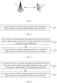
- an embodiment of this disclosure provides a data transmission method.
- the data transmission method may include step 201.
- Step 201 In a dual-connectivity mobility management procedure, UE performs a target operation on first uplink data according to first information.
- the target operation includes: in a case that the first information is used to indicate that a first path is capable of transmitting uplink data, transmitting the first uplink data on the first path, and/or in a case that the first information is used to indicate that a second path is incapable of transmitting target uplink data, and that the first uplink data belongs to the target uplink data, skipping transmitting the first uplink data on the second path.
- the first path is a source path (that is a path between the UE and a source cell), and the second path is a target path (that is a path between the UE and a target cell); or the first path is the target path, and the second path is the source path.
- the source path may be referred to as a source connection (a connection established between the UE and the source cell)
- the target path may be referred to as a target connection (that is, a connection established between the UE and the target cell).
- the dual-connectivity mobility procedure includes a handover procedure or an SCG change procedure (that is, SCG change procedure).
- SCG change procedure that is, SCG change procedure.
- the UE when the UE changes its serving cell, the UE establishes connection with both a source cell and a target cell, then releases the connection with the source cell, and only maintains the connection with the target cell.
- a PCell serving cell of the UE changes from cell 1 to cell 2.
- the change procedure the UE establishes connection with both the cell 1 and the cell 2, then releases the connection with the cell 1, and only maintains the connection with the cell 2.
- the UE before the UE releases the connection with the source cell, the UE can only transmit uplink data on one of the source connection and the target connection at a same moment. In this way, at the same moment, one of the two connections of the UE (the source connection or the target connection) is a connection capable of transmitting uplink data, and the other connection (the target connection or the source connection) is a connection incapable of transmitting the target uplink data.
- a data type of the target uplink data includes any one of the following: PDCP (Packet Data Convergence Protocol) layer data packet, PDCP layer control packet, and PDCP layer data.
- the PDCP layer data packet may be a PDCP Data PDU
- the PDCP layer control packet may be a PDCP control PDU (such as a robust header compression (ROHC) feedback packet)
- the PDCP layer data may be a PDCP PDU.
- ROHC robust header compression
- the PDCP layer data (such as PDCP PDU) includes but is not limited to: signaling radio bearer (SRB) control packet, SRB data packet, data radio bearer (SRB) control packet, DRB data packet, PDCP control packet, and PDCP data packet.
- SRB signaling radio bearer
- SRB data radio bearer
- SRB data radio bearer
- a data type of the target uplink data includes any one of the following: PDCP layer data packet of a data bearer, PDCP layer control packet of a data bearer, and PDCP layer data of a data bearer.
- the UE cannot transmit uplink PDCP Data PDUs on the target connection or the source connection; if the target connection or the source connection is a connection incapable of transmitting the target uplink data, the UE cannot transmit PDCP PDUs of an uplink DRB on the target connection or the source connection; and if the target connection or the source connection is a connection incapable of transmitting the target uplink data, the UE cannot transmit PDCP Data PDUs of an uplink DRB on the target connection or the source connection.
- the first information in a case that the first information is used to indicate that a second path is incapable of transmitting target uplink data, the first information is specifically used to indicate that no uplink resources can be allocated to a target channel for the second path.
- the target channel in a case that the first information is used to indicate that a second path is incapable of transmitting target uplink data, when the second path is the source path, the target channel includes a logical channel for a data bearer of the source path and/or a logical channel for a signaling bearer of the source path; or, when the second path is the target path, the target channel includes a logical channel for a data bearer of the target path.
- the data transmission method provided in this embodiment of this disclosure further includes step 201a.
- Step 201a In a case that a transmission path for first uplink data has changed to a first path, no uplink resources are allocated to a target channel for a second path according to a target uplink grant.
- the target uplink grant is used to indicate an uplink resource for the second path.
- the target channel refers to a logical channel.
- a MAC entity of the UE may allocate no uplink resources to a target channel for the second path according to the target uplink grant.
- another entity of the UE may alternatively be used to implement the procedure, which is not limited in this embodiment of this disclosure.
- a MAC entity of the UE allocates no uplink resources to "a target channel incapable of transmitting uplink data" through restriction by a logical channel prioritization (LCP) procedure.
- LCP logical channel prioritization
- Example a1 The UE currently can transmit uplink data only through the source connection, and "a logical channel incapable of transmitting uplink data" of the UE refers to a logical channel for a DRB corresponding to the target connection.
- a MAC entity of the UE allocates no uplink transmission resource to the logical channel for the DRB of the target connection when allocating uplink resources, but can still allocate uplink resources to a logical channel for the SRB, where the uplink grant 1 indicates an uplink transmission resource for the target connection.
- Example a2 The UE currently can transmit uplink data only through the target connection, and "a logical channel incapable of transmitting uplink data" of the UE refers to logical channels of all RBs (including DRBs and SRBs) corresponding to the source connection.
- a MAC entity of the UE allocates no uplink transmission resource to the logical channels for the RBs to which the source connection is connected when allocating uplink resources, where the uplink grant 1 indicates an uplink transmission resource for the target connection.
- the first information includes: a path ID of the first path and/or a path ID of the second path, where the path ID of the first path is used to identify the first path as a path capable of transmitting uplink data, and the path ID of the second path is used to identify the second path as a path incapable of transmitting the target uplink data.
- the method further includes step 201b.
- Step 201b In a case that UE receives a mobility management command, the UE marks a first path as a path capable of transmitting uplink data, and/or marks a second path as a path incapable of transmitting target uplink data.
- the first path is a path capable of transmitting uplink data by default
- the second path is a path incapable of transmitting the target uplink data by default.
- the mobility management command includes: a handover command, an SCG change command, and the like.
- the data transmission method provided in this embodiment of this disclosure further includes step 201c.
- Step 201c In a case that a transmission path for target uplink data has changed, the UE marks a first path as a path capable of transmitting uplink data, and/or marks a second path as a path incapable of transmitting target uplink data.
- the first path is a path previously incapable of transmitting uplink data
- the second path is a path previously capable of transmitting target uplink data.
- the UE marks the source path as a path capable of transmitting uplink data, and/or marks the target path as a path incapable of transmitting the target uplink data.
- the UE marks the source path (that is, the path previously incapable of transmitting uplink data) as a path incapable of transmitting the target uplink data, and marks the target path (that is, the path previously incapable of transmitting the target uplink data) as a path capable of transmitting uplink data.
- the marking the first path as a path capable of transmitting uplink data may specifically means that: a PDCP entity of the UE marks the first path as a path capable of transmitting uplink data; and the marking the second path as a path incapable of transmitting the target uplink data may specifically means that: a PDCP entity of the UE marks the second path as a path incapable of transmitting the target uplink data.
- another entity of the UE may alternatively be used to implement the procedure, which is not limited in this embodiment of this disclosure.
- the PDCP entity of the UE marks the uplink transmission path as "an uplink transmission path capable of transmitting uplink data" or "an uplink path incapable of transmitting uplink data”.
- the PDCP entity receives data transmission indication information from an lower layer and the data transmission indication information is data transmission indication information corresponding to "an uplink path incapable of transmitting uplink data"
- the PDCP entity of the UE does not generate or transmit data to the " the uplink path incapable of transmitting uplink data”.
- Example b1 A DRB of the UE currently can transmit uplink data only through the source connection, so that a PDCP entity of the DRB marks the target connection as "an uplink path incapable of transmitting uplink data".
- a MAC entity of the UE allocates an uplink resource for use by the target connection for the DRB and instructs the PDCP entity of the DRB to transmit data to the target connection.
- the PDCP entity of the DRB of the UE does not generate or transmit uplink data to the target connection.
- Example b2 A DRB of the UE currently can transmit uplink data only through the target connection, so that a PDCP entity of the DRB marks the source connection as "an uplink path incapable of transmitting uplink data".
- a MAC entity of the UE allocates an uplink resource for use by the source connection for the DRB and instructs the PDCP entity of the DRB to transmit data to the source connection.
- the PDCP entity of the DRB of the UE does not generate or transmit uplink data to the target connection.
- the MAC/RRC entity of the UE when the MAC entity/RRC entity of the UE receives information for uplink path change, the MAC/RRC entity indicates the transmission path for uplink data of a target PDCP entity.
- Example b3 When the UE receives a DC handover RRC message, an RRC entity of the UE indicates that a transmission path for uplink data of a PDCP entity of a DRB is a source path, and the PDCP entity of the DRB of the UE marks the source connection as "an uplink path capable of transmitting uplink data", and marks a target path as "an uplink path incapable of transmitting uplink data”.
- Example b4 After a successful random access of a target connection, or a successful handover, or a successful SCG change, and after a MAC entity of the UE receives an uplink grant for changing a transmission path for uplink data from a source path to a target path, the MAC entity of the UE indicates that a transmission path for uplink data of a PDCP entity of a DRB is the target path, then the PDCP entity of the DRB of the UE marks the source path as "an uplink transmission path incapable of transmitting uplink data", and marks the target path as "an uplink path capable of transmitting uplink data”.
- the UE performs a target operation on first uplink data according to first information, which means that in a case that the first information is used to indicate that a first path is capable of transmitting uplink data, the UE transmits the first uplink data on the first path, and in a case that the first information is used to indicate that a second path is incapable of transmitting target uplink data, and that the first uplink data belongs to the target uplink data, the UE skips transmitting the first uplink data on the second path. In this way, the UE determines whether the source path or the target path is capable of transmitting uplink data based on the first information, so that the uplink data are transmitted only on one path at a same moment, avoiding uplink data transmission interruption and delay.
- first information means that in a case that the first information is used to indicate that a first path is capable of transmitting uplink data, the UE transmits the first uplink data on the first path, and in a case that the first information is used to indicate that a second path is incapable of transmitting target
- the procedure of the UE transmitting the first uplink data on the first path specifically includes the following step 301a.
- Step 301a After a PDCP entity of the UE receives an uplink data transmission indication from an lower layer entity, the UE transmits first uplink data on a first path.
- the lower layer entity of the PDCP entity of the UE may be an RRC entity or a MAC entity.
- a first path is a target path
- a dual-connectivity mobility management procedure performed by a PDCP entity of UE when the target path is "an uplink transmission path incapable of transmitting uplink data", the PDCP entity of the UE is not allowed to transmit uplink data to the target path without receiving uplink data transmission indication from an lower layer entity; and/or, when the target path is "an uplink transmission path capable of transmitting uplink data", the PDCP entity of the UE is allowed to transmit uplink data to the target path without receiving uplink data transmission indication from an lower layer entity.
- the UE in a dual-connectivity mobility management procedure performed by UE, the UE cannot transmit uplink data to a first path without receiving uplink data transmission indication from an lower layer entity, thereby ensuring a successful uplink data transmission.
- the procedure of the UE transmitting the first uplink data on the first path specifically includes the following step 301b.
- the after the dual-connectivity mobility management procedure includes any one of the following: successful completion of a random access to the target cell, completion of a handover, completion of an SCG change, and release by the UE of a connection with the source cell.
- the lower layer entity of the PDCP entity of the UE may be an RRC entity or a MAC entity.
- a first path is a target path
- a dual-connectivity mobility management procedure by a PDCP entity of UE after a dual-connectivity mobility management procedure by a PDCP entity of UE, the PDCP entity of the UE is allowed to transmit uplink data to the target path without receiving uplink data transmission indication from an lower layer entity.
- the UE after the dual-connectivity mobility management procedure performed by UE, the UE re-allows uplink data to be transmitted to a first path without receiving uplink data transmission indication from an lower layer entity, thereby reducing uplink data transmission delay.
- the data transmission method provided in this embodiment of this disclosure further includes the following step 401a or step 401b.
- the UE transmits second information on a first path and transmits third information on a second path.
- the UE transmits second information on a first path.
- the second information is used to indicate a data amount of the second data
- the third information is used to indicate a data amount of the third data.
- the PDCP entity When a PDCP entity of the UE contains uplink data for a source connection and uplink data for a target connection, the PDCP entity distinguishes the different connections, collects data amounts for the different connections, and indicates them to a MAC entity of a corresponding connection.
- a method of indicating data for different connections to a MAC entity of a corresponding connection includes the following examples.
- Example 1 For a path capable of transmitting uplink data, a PDCP entity of the UE indicates to a MAC entity corresponding to the path capable of transmitting uplink data an amount of data that are buffered by the PDCP of the path and are to be transmitted through the path. For a path incapable of transmitting uplink data, a PDCP entity of the UE does not indicate to a MAC entity corresponding to the path incapable of transmitting uplink data an amount of data that are buffered by the PDCP of the path for transmission through the path. Correspondingly, the corresponding MAC entity may generate a corresponding buffer status report (BSR) according to the amount of data indicated by the PDCP entity.
- BSR buffer status report
- Example c1 Connections corresponding to a PDCP entity of one DRB include a source connection (for example, logical channel 1 of a source cell group) and a target connection (for example, logical channel 2 of a target cell group), where the source connection corresponds to a source MAC entity, and the target connection corresponds to a target MAC entity.
- a connection of the PDCP entity of the DRB that currently is capable of transmitting data is the source connection
- a connection of the PDCP entity of the DRB that currently is incapable of transmitting data is the target connection.
- data packets generated by the PDCP entity for the source connection includes: PDCP data PDUs and PDCP Control PDUs that are to be transmitted through the source connection
- data packets generated by the PDCP entity for the target connection include: PDCP Control PDUs that is to be transmitted through the target connection.
- the PDCP entity collects an amount of data transmitted through the source connection and indicates the amount to a source MAC entity, and does not indicate an amount of data transmitted through the target connection to a target MAC entity.
- Example 2 For a connection capable of transmitting uplink data, a PDCP entity of the UE indicates to a MAC entity corresponding to the connection capable of transmitting uplink data an amount of data that are buffered by the PDCP of the connection for transmission through the path. For a connection incapable of transmitting uplink data, a PDCP entity of the UE still first indicates to a MAC entity corresponding to the connection incapable of transmitting uplink data an amount of data that are buffered by the PDCP of the connection for transmission through the connection. The MAC entity generates a corresponding BSR (Buffer Status Report) according to the amount of data indicated by the PDCP.
- BSR Buffer Status Report
- Example c2 Connections corresponding to a PDCP entity of one DRB include a source connection (for example, logical channel 1 of a source cell group) and a target connection (for example, logical channel 2 of a target cell group), where the source connection corresponds to a source MAC entity, and the target connection corresponds to a target MAC entity.
- a connection of the PDCP entity of the DRB that currently is capable of transmitting data is the source connection
- a connection of the PDCP entity of the DRB that currently is incapable of transmitting data is the target connection.
- data packets generated by the PDCP entity of the DRB for the source connection includes: PDCP data PDUs and PDCP Control PDUs that are to be transmitted through the source connection
- data packets generated by the PDCP entity of the DRB for the target connection include: PDCP Control PDUs (such as a ROHC feedback packet) that is to be transmitted through the target connection.
- the PDCP entity of the DRB collects an amount of data transmitted through the source connection and indicates the amount to a source MAC entity, and collects and indicates to a target MAC entity an amount of data transmitted through the target connection.
- an execution order between steps 201a and 201b is not limited, nor an execution order between steps 201a, 201b, and 401a is limited, nor an execution order between steps 201a, 201b, and 401b is limited. This is not limited in this embodiment of this disclosure.
- the data transmission method provided in this embodiment of this disclosure can be implemented through the foregoing step 201 or through a combination scheme by combining step 201 and at least one of the foregoing steps 201a, 201b, 301a, 301b, 401a, and 401b. This is not limited in this embodiment of this disclosure.
- the foregoing first information is specifically used to indicate that no uplink resources can be allocated to a target channel for the second path.
- the foregoing target channel includes a logical channel for a data bearer of the source path and/or a logical channel for a signaling bearer of the source path; or, in a case that the second path is the target path, the target channel includes a logical channel for a data bearer of the target path.
- the execution module 501 is further configured to: in a case that a transmission path for the first uplink data has changed to the first path, allocate no uplink resources to a target channel for the second path according to a target uplink grant, where the target uplink grant is used to indicate an uplink resource for the second path.
- the execution module 501 is further configured to: in a case that the UE 500 receives a mobility management command, mark the first path as a path capable of transmitting uplink data, and/or mark the second path as a path incapable of transmitting the target uplink data, where the first path is a path capable of transmitting uplink data by default, and the second path is a path incapable of transmitting the target uplink data by default.
- the execution module 501 is further configured to: in a case that a transmission path for the target uplink data has changed, mark the first path as a path capable of transmitting uplink data, and/or mark the second path as a path incapable of transmitting the target uplink data, where the first path is a path previously incapable of transmitting uplink data, and the second path is a path previously capable of transmitting target uplink data.
- the UE 500 further includes a transmission module 502, where the transmission module 502 is configured to: after a PDCP entity the UE 500 receives an uplink data transmission indication from an lower layer entity, transmit first uplink data on a first path.
- the transmission module 502 is configured to: after the dual-connectivity mobility management procedure, in a case that the PDCP entity of the UE 500 receives no uplink data transmission indication from the lower layer entity, transmit the first uplink data on the first path, where the after the dual-connectivity mobility management procedure includes any one of the following: successful completion of a random access to the target cell, completion of a handover, completion of an SCG change, and release by the UE 500 of a connection with the source cell.
- the transmission module 502 is configured to: in a case that a PDCP entity of the UE 500 buffers second data and third data, that the second data is data transmitted through the first path, and that the third data is data transmitted through the second path, transmit second information on the first path and transmit third information on the second path, where the second information is used to indicate a data amount of the second data, and the third information is used to indicate a data amount of the third data.
- a data type of the foregoing target uplink data includes any one of the following: PDCP layer data packet, PDCP layer control packet, and PDCP layer data.
- the PDCP layer data packet is a PDCP layer data packet of a data bearer; and/or the PDCP layer data packet is a PDCP layer control packet of a data bearer; and/or the PDCP layer data packet is PDCP layer data of a data bearer.
- the module that must be included in the UE 500 is indicated by a solid line frame, such as the execution module 501; and the module that may or may not be included in the UE 500 is indicated by a dashed frame, such as the transmission module 502.
- the terminal device provided in this embodiment of this disclosure can implement all procedures in the foregoing method embodiment. To avoid repetition, details are not described herein again.
- the UE performs a target operation on first uplink data according to first information, which means that in a case that the first information is used to indicate that a first path is capable of transmitting uplink data, the UE transmits the first uplink data on the first path, and in a case that the first information is used to indicate that a second path is incapable of transmitting target uplink data, and that the first uplink data belongs to the target uplink data, the UE skips transmitting the first uplink data on the second path. In this way, the UE determines whether the source path or the target path is capable of transmitting uplink data based on the first information, so that the uplink data are transmitted only on one path at a same moment, avoiding uplink data transmission interruption and delay.
- first information which means that in a case that the first information is used to indicate that a first path is capable of transmitting uplink data, the UE transmits the first uplink data on the first path, and in a case that the first information is used to indicate that a second path is incapable of transmitting
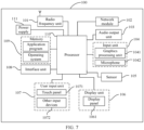
- FIG 7 is a schematic diagram of a hardware structure of a terminal device for implementing the embodiments of this disclosure.
- the terminal device 100 includes but is not limited to components such as a radio frequency unit 101, a network module 102, an audio output unit 103, an input unit 104, a sensor 105, a display unit 106, a user input unit 107, an interface unit 108, a memory 109, a processor 110, and a power supply 111.
- a radio frequency unit 101 such as a radio frequency unit 101, a network module 102, an audio output unit 103, an input unit 104, a sensor 105, a display unit 106, a user input unit 107, an interface unit 108, a memory 109, a processor 110, and a power supply 111.
- Persons skilled in the art can understand that the structure of the terminal device 100 shown in FIG. 7 does not constitute any limitation on the terminal device.
- the terminal device 100 may include more or fewer components than those shown in the figure, or combine some
- the terminal device 100 includes but is not limited to a mobile phone, a tablet computer, a laptop computer, a palmtop computer, an in-vehicle terminal device, a wearable device, a pedometer, and the like.
- the processor 110 is configured to perform a target operation on first uplink data according to first information in a dual-connectivity mobility management procedure, where the target operation includes: in a case that the first information is used to indicate that a first path is capable of transmitting uplink data, transmitting the first uplink data on the first path, and/or in a case that the first information is used to indicate that a second path is incapable of transmitting target uplink data, and that the first uplink data belongs to the target uplink data, skipping transmitting the first uplink data on the second path; and the first path is a source path between the UE and a source cell, the second path is a target path between the UE and a target cell, or, the first path is the target path, and the second path is the source path.
- the terminal device performs a target operation on first uplink data according to first information, which means that in a case that the first information is used to indicate that a first path is capable of transmitting uplink data, the terminal device transmits the first uplink data on the first path, and in a case that the first information is used to indicate that a second path is incapable of transmitting target uplink data, and that the first uplink data belongs to the target uplink data, the terminal device skips transmitting the first uplink data on the second path. In this way, the terminal device determines whether the source path or the target path is capable of transmitting uplink data based on the first information, so that the uplink data are transmitted only on one path at a same moment, avoiding uplink data transmission interruption and delay.
- first information which means that in a case that the first information is used to indicate that a first path is capable of transmitting uplink data, the terminal device transmits the first uplink data on the first path, and in a case that the first information is used to indicate that a second path is incapable of transmitting
- the radio frequency unit 101 may be configured to transmit or receive a signal in an information transmitting/receiving or call process. Specifically, the radio frequency unit 101 receives downlink data from a base station, transmits the downlink data to the processor 110 for processing, and transmits uplink data to the base station.
- the radio frequency unit 101 includes but is not limited to an antenna, at least one amplifier, a transceiver, a coupler, a low noise amplifier, a duplexer, and the like.
- the radio frequency unit 101 may further communicate with a network and other devices via a wireless communications system.
- the audio output unit 103 may convert audio data received by the radio frequency unit 101 or the network module 102 or stored in the memory 109 into an audio signal and output the audio signal as a sound.
- the audio output unit 103 may further provide audio output (for example, a call signal received sound or a message received sound) related to a specific function performed by the terminal device 100.
- the audio output unit 103 includes a speaker, a buzzer, a receiver, and the like.
- the input unit 104 is configured to receive an audio signal or a video signal.
- the input unit 104 may include a graphics processing unit (GPU) 1041 and a microphone 1042.
- the graphics processing unit 1041 processes image data of a static picture or a video obtained by an image capture apparatus (for example, a camera) in an image capture mode or a video capture mode.
- a processed image frame may be displayed on the display unit 106.
- the image frame processed by the graphics processing unit 1041 may be stored in the memory 109 (or another storage medium) or transmitted by using the radio frequency unit 101 or the network module 102.
- the microphone 1042 is capable of receiving sounds and processing such sounds into audio data.
- the processed audio data can be converted into a format output that can be transmitted to a mobile communication base station through the radio frequency unit 101 in a telephone call mode.
- the terminal device 100 further includes at least one sensor 105, for example, an optical sensor, a motion sensor, and other sensors.
- the optical sensor includes an ambient light sensor and a proximity sensor.
- the ambient light sensor may adjust brightness of a display panel 1061 based on intensity of ambient light.
- the proximity sensor may disable the display panel 1061 and/or backlight.
- an accelerometer sensor may detect magnitudes of accelerations in all directions (usually three axes), may detect a magnitude and a direction of gravity when the terminal is in a static state, and may be applied to posture recognition of the terminal device (for example, landscape/portrait mode switching, a related games, or magnetometer posture calibration), functions related to vibration recognition (for example, a pedometer or tapping), or the like.
- the sensor 105 may further include a fingerprint sensor, a pressure sensor, an iris sensor, a molecular sensor, a gyroscope, a barometer, a hygrometer, a thermometer, or an infrared sensor. Details are not described herein.
- the display unit 106 is configured to display information input by the user or information provided to the user.
- the display unit 106 may include the display panel 1061.
- the display panel 1061 may be configured in a form of a liquid crystal display (LCD), an organic light-emitting diode (OLED), or the like.
- the user input unit 107 may be configured to receive entered numerical or character information, and generate key signal input that is related to user setting and function control of the terminal device 100.
- the user input unit 107 includes a touch panel 1071 and other input devices 1072.
- the touch panel 1071 also referred to as a touchscreen, may capture a touch operation performed by a user on or near the touch panel (for example, an operation performed by the user on the touch panel 1071 or near the touch panel 1071 by using a finger or any appropriate object or accessory such as a stylus).
- the touch panel 1071 may include two parts: a touch detection apparatus and a touch controller.
- the touch detection apparatus detects a touch orientation of the user, detects a signal brought by the touch operation, and transmits the signal to the touch controller.
- the touch controller receives touch information from the touch detection apparatus, converts the touch information into contact coordinates, transmits the contact coordinates to the processor 110, receives a command transmitted by the processor 110, and executes the command.
- the touch panel 1071 may be implemented in a plurality of forms, for example, as a resistive, capacitive, infrared, or surface acoustic wave touch panel.
- the user input unit 107 may further include other input devices 1072.
- the other input devices 1072 may include but are not limited to a physical keyboard, a function key (such as a volume control key or a switch key), a trackball, a mouse, and a joystick. Details are not described herein.
- the touch panel 1071 may cover the display panel 1061.
- the touch panel 1071 transmits the touch operation to the processor 110 to determine a type of a touch event.
- the processor 110 provides a corresponding visual output on the display panel 1061 based on the type of the touch event.
- the touch panel 1071 and the display panel 1061 serve as two separate components to implement input and output functions of the terminal device 100.
- the touch panel 1071 and the display panel 1061 may be integrated to implement the input and output functions of the terminal device 100. This is not specifically limited herein.
- the interface unit 108 is an interface for connecting an external apparatus to the terminal device 100.
- the external apparatus may include a wired or wireless headphone port, an external power supply (or battery charger) port, a wired or wireless data port, a memory card port, a port for connecting an apparatus with an identification module, an audio input/output (I/O) port, a video I/O port, a headset port, or the like.
- the interface unit 108 may be configured to receive an input (for example, data information or power) from an external apparatus and transmit the received input to one or more elements within the terminal device 100, or may be configured to transmit data between the terminal device 100 and the external apparatus.
- the memory 109 may be configured to store software programs and various data.
- the memory 109 may mainly include a program storage region and a data storage region.
- the program storage region may store an operating system, an application program required by at least one function (for example, an audio play function or an image play function), and the like.
- the data storage region may store data (for example, audio data and a phone book) created based on usage of the mobile phone.
- the memory 109 may include a high-speed random access memory, and may further include a non-volatile memory such as a disk storage device, a flash memory device, or another volatile solid-state storage device.
- the processor 110 is a control center of the terminal device 100, uses various interfaces and lines to connect all parts of the entire terminal device 100, and performs various functions and data processing of the terminal device 100 by running or executing the software program and/or module stored in the memory 109 and invoking data stored in the memory 109, thereby performing overall monitoring on the terminal device 100.
- the processor 110 may include one or more processing units.
- the processor 110 may integrate an application processor and a modem processor.
- the application processor mainly processes an operating system, a user interface, an application program, and the like.
- the modem processor mainly processes wireless communication. It can be understood that the modem processor may alternatively be not integrated in the processor 110.
- the terminal device 100 may further include a power supply 111 (for example, a battery) that supplies power to the components.
- a power supply 111 for example, a battery
- the power supply 111 may be logically connected to the processor 110 by using a power management system, so as to implement functions such as charging management, discharging management, and power consumption management by using the power management system.
- the terminal device 100 includes some functional modules that are not illustrated. Details are not described herein.
- an embodiment of this disclosure further provides a terminal device, including a processor, a memory, and a computer program stored in the memory and capable of running on the processor.
- a terminal device including a processor, a memory, and a computer program stored in the memory and capable of running on the processor.
- the computer program is executed by the processor, the procedures of the data transmission method in the foregoing embodiment are implemented, with the same technical effects achieved. To avoid repetition, details are not described herein again.
- An embodiment of this disclosure further provides a computer-readable storage medium, where the computer-readable storage medium stores a computer program, and when the computer program is executed by a processor, the plurality of procedures of the data transmission method in the foregoing embodiment are implemented, with the same technical effects achieved. To avoid repetition, details are not described herein again.
- the computer-readable storage medium includes a read-only memory (ROM), a random access memory (RAM), a magnetic disk, an optical disc, or the like.
- the computer software product is stored in a storage medium (for example, a ROM/RAM, a magnetic disc, or an optical disc), and includes several instructions for instructing a terminal Device(which may be a mobile phone, a computer, a server, an air conditioner, a network device, or the like) to perform the methods described in the plurality of embodiments of this disclosure.
- a storage medium for example, a ROM/RAM, a magnetic disc, or an optical disc
Landscapes
- Engineering & Computer Science (AREA)
- Signal Processing (AREA)
- Computer Networks & Wireless Communication (AREA)
- Mobile Radio Communication Systems (AREA)
Claims (14)
- Datenübertragungsverfahren, das auf ein Benutzergerät UE angewendet wird, wobei das Verfahren die folgenden Schritte umfasst:in einem Dual-Konnektivität-Mobilitätsmanagementverfahren in einem Fall, in dem erste Informationen verwendet werden, um anzuzeigen, dass ein erster Pfad in der Lage ist, Uplink-Daten zu übertragen, Übertragen von ersten Uplink-Daten auf dem ersten Pfad, und/oder in einem Fall, in dem die erste Informationen verwendet werden, um anzuzeigen, dass ein zweiter Pfad nicht in der Lage ist, Ziel-Uplink-Daten zu übertragen, und dass die ersten Uplink-Daten die Ziel-Uplink-Daten sind, Überspringen von Übertragen von ersten Uplink-Daten auf dem zweiten Pfad; und dadurch gekennzeichnet, dass ein Datentyp der Ziel-Uplink-Daten Folgendes umfasst: PDCP-Schicht-Datenpaket, oder PDCP-Schicht-Steuerpaket, oder PDCP-Schicht-Daten,wobei in einem Fall, dass eine PDCP-Entität des UE zweite Daten und dritte Daten puffert, dass die zweiten Daten Daten sind, die über den ersten Pfad übertragen werden, und dass die dritten Daten Daten sind, die über einen zweiten Pfad übertragen werden, das Verfahren ferner die folgenden Schritte umfasst:Übertragen von zweiten Informationen an eine MAC-Entität, die dem ersten Pfad entspricht, und Übertragen von dritten Informationen an eine MAC-Entität, die dem zweiten Pfad entspricht; wobeidie zweiten Informationen verwendet werden, um eine Datenmenge der zweiten Daten anzuzeigen, und die dritten Informationen verwendet werden, um eine Datenmenge der dritten Daten anzuzeigen, der erste Pfad ein Zielpfad eines Übergabeverfahrens oder eines SCG-Änderungsverfahrens ist und der zweite Pfad ein Quellpfad eines Übergabeverfahrens oder eines SCG-Änderungsverfahrens ist.
- Verfahren nach Anspruch 1, wobei in einem Fall, in dem die ersten Informationen verwendet werden, um anzuzeigen, dass der zweite Pfad nicht in der Lage ist, die Ziel-Uplink-Daten zu übertragen, die ersten Informationen speziell verwendet werden, um anzuzeigen, dass einem Zielkanal für den zweiten Pfad keine Uplink-Ressourcen zugewiesen werden können.
- Verfahren gemäß Anspruch 2, wobei in einem Fall, in dem der zweite Pfad der Quellpfad eines Übergabeverfahrens oder eines SCG-Änderungsverfahrens ist, der Zielkanal einen logischen Kanal für einen Datenträger des Quellpfads eines Übergabeverfahrens oder eines SCG-Änderungsverfahrens und/oder einen logischen Kanal für einen Signalisierungsträger des Quellpfads eines Übergabeverfahrens oder eines SCG-Änderungsverfahrens aufweist; oder
in einem Fall, in dem der zweite Pfad der Zielpfad eines Übergabeverfahrens oder eines SCG-Änderungsverfahrens ist, der Zielkanal einen logischen Kanal für einen Datenträger des Zielpfads eines Übergabeverfahrens oder eines SCG-Änderungsverfahrens aufweist. - Verfahren gemäß Anspruch 2 oder 3, wobei das Verfahren vor dem Übertragen der ersten Uplink-Daten auf dem ersten Pfad ferner den folgenden Schritt umfasst:in einem Fall, in dem ein Übertragungspfad für die ersten Uplink-Daten zu dem ersten Pfad geändert wurde, Zuweisen von keinen Uplink-Ressourcen zu einem Zielkanal für den zweiten Pfad gemäß einer Ziel-Uplink-Gewährung; wobeidie Ziel-Uplink-Gewährung verwendet wird, um eine Uplink-Ressource für den zweiten Pfad anzuzeigen.
- Verfahren gemäß Anspruch 4, wobei das Zuweisen von keinen Uplink-Ressourcen zu einem Zielkanal für den zweiten Pfad gemäß einer Ziel-Uplink-Gewährung umfasst:
Zuweisen von keinen Uplink-Ressourcen zu einem Zielkanal für den zweiten Pfad gemäß einer Ziel-Uplink-Zuweisung durch eine MAC-Entität des UE. - Verfahren gemäß Anspruch 1, wobei das Verfahren vor dem Übertragen der ersten Uplink-Daten auf dem ersten Pfad ferner umfasst:in einem Fall, in dem das UE einen Mobilitätsverwaltungsbefehl empfängt, Markieren des ersten Pfads als einen Pfad, der Uplink-Daten übertragen kann, und/oder Markieren des zweiten Pfads als einen Pfad, der die Ziel-Uplink-Daten nicht übertragen kann; wobeider erste Pfad standardmäßig ein Pfad ist, der Uplink-Daten übertragen kann, und der zweite Pfad standardmäßig ein Pfad ist, der die Ziel-Uplink-Daten nicht übertragen kann.
- Verfahren nach Anspruch 1, wobei das Verfahren vor dem Übertragen der ersten Uplink-Daten auf dem ersten Pfad ferner umfasst:in einem Fall, in dem sich ein Übertragungspfad für die Ziel-Uplink-Daten geändert hat, Markieren des ersten Pfads als einen Pfad, der Uplink-Daten übertragen kann, und/oder Markieren des zweiten Pfads als einen Pfad, der die Ziel-Uplink-Daten nicht übertragen kann; wobeider erste Pfad ein Pfad ist, der zuvor nicht in der Lage war, Uplink-Daten zu übertragen, und der zweite Pfad ein Pfad ist, der zuvor in der Lage war, Ziel-Uplink-Daten zu übertragen.
- Verfahren gemäß Anspruch 6 oder 7, wobeidas Markieren des ersten Pfads als ein Pfad, der in der Lage ist, Uplink-Daten zu übertragen, umfasst:Markieren des ersten Pfads als ein Pfad, der in der Lage ist, Uplink-Daten zu übertragen, durch eine PDCP-Entität des UE; unddas Markieren des zweiten Pfads als ein Pfad, der nicht in der Lage ist, die Ziel-Uplink-Daten zu übertragen, umfasst:
Markieren des zweiten Pfads als ein Pfad, der nicht in der Lage ist, die Ziel-Uplink-Daten zu übertragen, durch die PDCP-Entität des UE. - Verfahren gemäß Anspruch 1, wobei das Übertragen der ersten Uplink-Daten auf dem ersten Pfad umfasst:
nachdem eine PDCP-Entität des UE eine Uplink-Datenübertragungsanzeige von einer Entität einer niedrigeren Schicht empfängt, Übertragen der ersten Uplink-Daten auf dem ersten Pfad. - Verfahren gemäß Anspruch 1, wobei das Verfahren nach dem Dual-Konnektivität-Mobilitätsmanagementverfahren ferner umfasst:in einem Fall, dass eine PDCP-Entität des UE keine Uplink-Datenübertragungsanzeige von einer Entität einer niedrigeren Schicht empfängt, Übertragen der ersten Uplink-Daten auf dem ersten Pfad; wobeidas Dual-Konnektivität-Mobilitätsmanagementverfahren eines der folgenden umfasst: erfolgreichen Abschluss eines wahlfreien Zugriffs auf die Zielzelle eines Übergabeverfahrens oder eines SCG-Änderungsverfahrens, Abschluss einer Übergabe, Abschluss einer SCG-Änderung und Freigabe einer Verbindung mit der Quellzelle eines Übergabeverfahrens oder eines SCG-Änderungsverfahrens durch das UE.
- Verfahren nach Anspruch 1, wobei das PDCP-Schicht-Datenpaket ein PDCP-Schicht-Datenpaket eines Datenträgers ist; und/oder das PDCP-Schicht-Datenpaket ein PDCP-Schicht-Steuerpaket eines Datenträgers ist; und/oder das PDCP-Schicht-Datenpaket PDCP-Schicht-Daten eines Datenträgers ist.
- Benutzergerät UE (500), aufweisend:ein Ausführungsmodul (501), das so konfiguriert ist, dass es: in einem Dual-Konnektivität-Mobilitätsmanagementverfahren in einem Fall, in dem erste Informationen verwendet werden, um anzuzeigen, dass ein erster Pfad in der Lage ist, Uplink-Daten zu übertragen, die ersten Uplink-Daten auf dem ersten Pfad überträgt, und/oder in einem Fall, in dem die ersten Informationen verwendet werden, um anzuzeigen, dass ein zweiter Pfad nicht in der Lage ist, Ziel-Uplink-Daten zu übertragen, und dass die ersten Uplink-Daten die Ziel-Uplink-Daten sind, Übertragen der ersten Uplink-Daten auf dem zweiten Pfad überspringt; und dadurch gekennzeichnet, dass ein Datentyp der Ziel-Uplink-Daten aufweist: PDCP-Schicht-Datenpaket, oder PDCP-Schicht-Steuerpaket oder PDCP-Schicht-Daten,wobei das Übertragungsmodul (502) so konfiguriert ist, dass es in einem Fall, in dem eine PDCP-Entität des UE zweite Daten und dritte Daten puffert, wobei die zweiten Daten Daten sind, die über den ersten Pfad übertragen werden, und die dritten Daten Daten sind, die über den zweiten Pfad übertragen werden, zweite Informationen an eine MAC-Entität überträgt, die dem ersten Pfad entspricht, und dritte Informationen an eine MAC-Entität überträgt, die dem zweiten Pfad entspricht; wobeidie zweiten Informationen verwendet werden, um eine Datenmenge der zweiten Daten anzuzeigen, und die dritten Informationen verwendet werden, um eine Datenmenge der dritten Daten anzuzeigen;der erste Pfad ein Zielpfad eines Übergabeverfahrens oder eines SCG-Änderungsverfahrens ist und der zweite Pfad der Quellpfad eines Übergabeverfahrens oder eines SCG-Änderungsverfahrens ist.
- UE gemäß Anspruch 12, wobei in einem Fall, in dem die ersten Informationen verwendet werden, um anzuzeigen, dass der zweite Pfad nicht in der Lage ist, die Ziel-Uplink-Daten zu übertragen, die ersten Informationen speziell verwendet werden, um anzuzeigen, dass einem Zielkanal für den zweiten Pfad keine Uplink-Ressourcen zugewiesen sind.
- Computerlesbares Speichermedium, wobei das computerlesbare Speichermedium ein Computerprogramm speichert und bei Ausführung des Computerprogramms durch einen Prozessor die Schritte des Datenübertragungsverfahrens gemäß einem der Ansprüche 1 bis 11 implementiert werden.
Applications Claiming Priority (2)
| Application Number | Priority Date | Filing Date | Title |
|---|---|---|---|
| CN201910708720.6A CN111800832B (zh) | 2019-08-01 | 2019-08-01 | 数据发送方法、用户设备ue及介质 |
| PCT/CN2020/100278 WO2021017755A1 (zh) | 2019-08-01 | 2020-07-03 | 数据发送方法及用户设备 |
Publications (4)
| Publication Number | Publication Date |
|---|---|
| EP4009699A1 EP4009699A1 (de) | 2022-06-08 |
| EP4009699A4 EP4009699A4 (de) | 2022-10-05 |
| EP4009699B1 true EP4009699B1 (de) | 2025-03-12 |
| EP4009699C0 EP4009699C0 (de) | 2025-03-12 |
Family
ID=72804955
Family Applications (1)
| Application Number | Title | Priority Date | Filing Date |
|---|---|---|---|
| EP20848227.3A Active EP4009699B1 (de) | 2019-08-01 | 2020-07-03 | Datensendeverfahren und benutzerausrüstung |
Country Status (8)
| Country | Link |
|---|---|
| US (1) | US12200474B2 (de) |
| EP (1) | EP4009699B1 (de) |
| JP (1) | JP7392106B2 (de) |
| KR (1) | KR102755273B1 (de) |
| CN (1) | CN111800832B (de) |
| BR (1) | BR112022001361A2 (de) |
| ES (1) | ES3021815T3 (de) |
| WO (1) | WO2021017755A1 (de) |
Families Citing this family (2)
| Publication number | Priority date | Publication date | Assignee | Title |
|---|---|---|---|---|
| CN111800832B (zh) * | 2019-08-01 | 2021-09-17 | 维沃移动通信有限公司 | 数据发送方法、用户设备ue及介质 |
| CN114557036B (zh) * | 2019-11-07 | 2024-04-02 | Lg电子株式会社 | 利用有条件的pscell配置的scg故障处理 |
Family Cites Families (42)
| Publication number | Priority date | Publication date | Assignee | Title |
|---|---|---|---|---|
| CN100463560C (zh) * | 2005-06-06 | 2009-02-18 | 上海原动力通信科技有限公司 | 基于时分双工系统的小区切换方法 |
| GB2449629A (en) | 2007-05-01 | 2008-12-03 | Nec Corp | Buffering numbered unsegmented PDCP SDUs in 3GPP system to assist efficient hard handover |
| CN103281782B (zh) * | 2009-01-23 | 2016-08-24 | 华为技术有限公司 | 上行载频管理方法、设备和系统 |
| KR20140102112A (ko) | 2013-02-13 | 2014-08-21 | 주식회사 케이티 | 스몰셀 활성화 또는 비활성화 방법 및 장치 |
| KR102206431B1 (ko) * | 2013-02-22 | 2021-01-22 | 삼성전자 주식회사 | 다수의 E-NodeB들과 사용자 단말 간에 동시 접속을 제공하기 위한 방법 및 시스템 |
| US20160286449A1 (en) | 2013-03-22 | 2016-09-29 | Lg Electronics Inc. | Method for performing handover in wireless access system supporting double connection mode, and apparatus supporting same |
| WO2014161170A1 (en) * | 2013-04-03 | 2014-10-09 | Broadcom Corporation | Method and apparatus for time switched uplink in a dual connectivity environment |
| WO2015012591A1 (ko) | 2013-07-25 | 2015-01-29 | 주식회사 케이티 | 캐리어 병합을 수행하는 방법과 그 장치 |
| US9730152B2 (en) * | 2013-09-27 | 2017-08-08 | Mediatek Inc. | UE enhancement in FDD-TDD joint operation networks |
| WO2015062043A1 (zh) | 2013-10-31 | 2015-05-07 | 华为技术有限公司 | 双连接模式下的资源请求方法及终端、主基站和辅基站 |
| WO2015113207A1 (zh) * | 2014-01-28 | 2015-08-06 | 华为技术有限公司 | 一种安全密钥更改方法和基站及用户设备 |
| US9867096B2 (en) * | 2014-05-09 | 2018-01-09 | Telefonaktiebolaget Lm Ericsson (Publ) | Uplink reconfiguration for split bearer in dual connectivity |
| WO2016021662A1 (ja) * | 2014-08-06 | 2016-02-11 | 株式会社Nttドコモ | ユーザ装置及び基地局 |
| JP5852193B1 (ja) | 2014-08-06 | 2016-02-03 | 株式会社Nttドコモ | ユーザ装置 |
| US10383009B2 (en) | 2014-11-06 | 2019-08-13 | Nokia Solutions And Networks Oy | Handover of a terminal in dual connectivity mode |
| CN105874856B (zh) | 2014-12-05 | 2019-10-22 | 华为技术有限公司 | 一种tdd上下行不同配置的定位方法和装置 |
| EP4145757A1 (de) * | 2015-01-28 | 2023-03-08 | Interdigital Patent Holdings, Inc. | Auslösen von aperiodischen sondierungsreferenzsignalen |
| CN107710667B (zh) * | 2015-07-01 | 2021-05-04 | Lg 电子株式会社 | 在双连接中发送数据的方法及其设备 |
| EP3941108B1 (de) * | 2015-07-20 | 2023-10-11 | Samsung Electronics Co., Ltd. | Kommunikationsverfahren und -vorrichtung in einem kommunikationssystem |
| KR102038500B1 (ko) * | 2016-03-24 | 2019-10-31 | 주식회사 케이티 | 업링크 데이터 처리 방법 및 그 장치 |
| CN106060870B (zh) * | 2016-06-02 | 2018-08-14 | 爱立信(中国)通信有限公司 | 一种无线网络接入节点、用户设备以及调整用户设备上行传输和切换上行数据链路的方法 |
| CN107690163A (zh) * | 2016-08-03 | 2018-02-13 | 中兴通讯股份有限公司 | 小区切换方法及装置 |
| CN107708104B (zh) * | 2016-08-03 | 2022-03-01 | 中兴通讯股份有限公司 | 辅基站变更的方法及装置 |
| US20180084464A1 (en) * | 2016-09-22 | 2018-03-22 | Qualcomm Incorporated | Long term evolution (lte) handover with the same secondary link |
| US11303701B2 (en) * | 2016-12-11 | 2022-04-12 | Nicira Inc. | Handling failure at logical routers |
| US20180270679A1 (en) * | 2017-03-20 | 2018-09-20 | Nokia Technologies Oy | Reliability-based multi-link communications |
| CN112738858B (zh) | 2017-03-24 | 2022-05-31 | 华为技术有限公司 | 切换的方法和设备 |
| US11516796B2 (en) * | 2017-04-14 | 2022-11-29 | Asustek Computer Inc. | Method and apparatus of requesting semi-persistent scheduling resource for transmission of data duplication in a wireless communication system |
| US11089504B2 (en) * | 2017-05-16 | 2021-08-10 | Lg Electronics Inc. | Apparatus and method for a user equipment (UE) operating a split bearer |
| US10609589B2 (en) * | 2017-06-02 | 2020-03-31 | Motorola Mobility Llc | Determining data available for transmission |
| CN109150425B (zh) * | 2017-06-15 | 2020-04-24 | 维沃移动通信有限公司 | 一种数据处理方法、移动终端及计算机可读存储介质 |
| EP3641258B1 (de) * | 2017-08-03 | 2021-10-13 | Huawei Technologies Co., Ltd. | Datenübertragungsverfahren |
| US10785778B2 (en) * | 2017-08-12 | 2020-09-22 | Lg Electronics Inc. | Method for handling for an uplink split operation in wireless communication system and a device therefor |
| JP2021503194A (ja) * | 2017-09-28 | 2021-02-04 | オッポ広東移動通信有限公司Guangdong Oppo Mobile Telecommunications Corp., Ltd. | パスハンドオーバー方法及び端末装置 |
| KR102089358B1 (ko) * | 2017-09-28 | 2020-03-16 | 텔레폰악티에볼라겟엘엠에릭슨(펍) | Pdcp ul 스플릿 및 사전-처리 |
| EP4184834B1 (de) * | 2018-01-10 | 2025-03-05 | Sharp Kabushiki Kaisha | Verfahren zur datenübertragung des paketdatenkonvergenzprotokolls (pdcp) in drahtlosen kommunikationssystemen |
| KR20200046372A (ko) * | 2018-10-24 | 2020-05-07 | 에스케이텔레콤 주식회사 | 업링크 스케줄링장치 및 업링크 스케줄링 방법, 단말장치 |
| CN109673023B (zh) * | 2018-11-12 | 2022-04-01 | 中国科学院上海高等研究院 | 链路通信模式的操作方法、系统、计算机存储介质、设备 |
| CN113424620A (zh) * | 2019-02-19 | 2021-09-21 | 华为技术有限公司 | 跨LF和mmWave的服务连续性的方法和装置 |
| US11146992B2 (en) * | 2019-02-25 | 2021-10-12 | Samsung Electronics Co., Ltd. | Method and apparatus for handling uplink bearer split configuration in multi-connectivity system |
| KR102810683B1 (ko) * | 2019-05-17 | 2025-05-22 | 삼성전자 주식회사 | 무선 통신 시스템에서 지연 감소를 위한 전송 경로 결정 방법 및 장치 |
| CN111800832B (zh) * | 2019-08-01 | 2021-09-17 | 维沃移动通信有限公司 | 数据发送方法、用户设备ue及介质 |
-
2019
- 2019-08-01 CN CN201910708720.6A patent/CN111800832B/zh active Active
-
2020
- 2020-07-03 BR BR112022001361A patent/BR112022001361A2/pt unknown
- 2020-07-03 ES ES20848227T patent/ES3021815T3/es active Active
- 2020-07-03 JP JP2022506173A patent/JP7392106B2/ja active Active
- 2020-07-03 WO PCT/CN2020/100278 patent/WO2021017755A1/zh not_active Ceased
- 2020-07-03 KR KR1020227002912A patent/KR102755273B1/ko active Active
- 2020-07-03 EP EP20848227.3A patent/EP4009699B1/de active Active
-
2022
- 2022-01-27 US US17/586,371 patent/US12200474B2/en active Active
Also Published As
| Publication number | Publication date |
|---|---|
| CN111800832B (zh) | 2021-09-17 |
| EP4009699C0 (de) | 2025-03-12 |
| ES3021815T3 (en) | 2025-05-27 |
| KR102755273B1 (ko) | 2025-01-14 |
| JP7392106B2 (ja) | 2023-12-05 |
| BR112022001361A2 (pt) | 2022-03-22 |
| EP4009699A1 (de) | 2022-06-08 |
| CN111800832A (zh) | 2020-10-20 |
| US20220150773A1 (en) | 2022-05-12 |
| EP4009699A4 (de) | 2022-10-05 |
| WO2021017755A1 (zh) | 2021-02-04 |
| KR20220028009A (ko) | 2022-03-08 |
| JP2022544071A (ja) | 2022-10-17 |
| US12200474B2 (en) | 2025-01-14 |
Similar Documents
| Publication | Publication Date | Title |
|---|---|---|
| US11502737B2 (en) | Beam failure recovery method in multi-carrier system and apparatus | |
| US12127286B2 (en) | Wireless communication method and terminal device | |
| US12177653B2 (en) | Path switching method and device | |
| US12143838B2 (en) | Processing method and terminal | |
| US11477669B2 (en) | Method of transmitting beam failure recovery request and user equipment | |
| US12245326B2 (en) | Message transmission method and terminal | |
| WO2021057655A1 (zh) | 信息指示方法、设备及系统 | |
| US12200474B2 (en) | Data transmission method and user equipment | |
| US20210058817A1 (en) | Operation control method, mobile communications terminal, and network-side device | |
| US12035351B2 (en) | Data processing method and device using transmission priorities | |
| CN112788769B (zh) | 一种信息处理方法、设备及系统 | |
| HK40066273B (en) | Data sending method and user equipment | |
| HK40066273A (en) | Data sending method and user equipment | |
| CA3153084C (en) | Message transmission method and terminal | |
| CN111132293A (zh) | 信息传输方法、设备及系统 | |
| HK40067932A (en) | Message transmission method and terminal |
Legal Events
| Date | Code | Title | Description |
|---|---|---|---|
| STAA | Information on the status of an ep patent application or granted ep patent |
Free format text: STATUS: THE INTERNATIONAL PUBLICATION HAS BEEN MADE |
|
| PUAI | Public reference made under article 153(3) epc to a published international application that has entered the european phase |
Free format text: ORIGINAL CODE: 0009012 |
|
| STAA | Information on the status of an ep patent application or granted ep patent |
Free format text: STATUS: REQUEST FOR EXAMINATION WAS MADE |
|
| 17P | Request for examination filed |
Effective date: 20220225 |
|
| AK | Designated contracting states |
Kind code of ref document: A1 Designated state(s): AL AT BE BG CH CY CZ DE DK EE ES FI FR GB GR HR HU IE IS IT LI LT LU LV MC MK MT NL NO PL PT RO RS SE SI SK SM TR |
|
| REG | Reference to a national code |
Ref country code: HK Ref legal event code: DE Ref document number: 40066273 Country of ref document: HK |
|
| A4 | Supplementary search report drawn up and despatched |
Effective date: 20220906 |
|
| RIC1 | Information provided on ipc code assigned before grant |
Ipc: H04W 36/18 20090101ALI20220831BHEP Ipc: H04W 76/15 20180101ALI20220831BHEP Ipc: H04W 36/00 20090101AFI20220831BHEP |
|
| DAV | Request for validation of the european patent (deleted) | ||
| DAX | Request for extension of the european patent (deleted) | ||
| STAA | Information on the status of an ep patent application or granted ep patent |
Free format text: STATUS: EXAMINATION IS IN PROGRESS |
|
| 17Q | First examination report despatched |
Effective date: 20231117 |
|
| GRAP | Despatch of communication of intention to grant a patent |
Free format text: ORIGINAL CODE: EPIDOSNIGR1 |
|
| STAA | Information on the status of an ep patent application or granted ep patent |
Free format text: STATUS: GRANT OF PATENT IS INTENDED |
|
| INTG | Intention to grant announced |
Effective date: 20241009 |
|
| GRAS | Grant fee paid |
Free format text: ORIGINAL CODE: EPIDOSNIGR3 |
|
| GRAA | (expected) grant |
Free format text: ORIGINAL CODE: 0009210 |
|
| STAA | Information on the status of an ep patent application or granted ep patent |
Free format text: STATUS: THE PATENT HAS BEEN GRANTED |
|
| AK | Designated contracting states |
Kind code of ref document: B1 Designated state(s): AL AT BE BG CH CY CZ DE DK EE ES FI FR GB GR HR HU IE IS IT LI LT LU LV MC MK MT NL NO PL PT RO RS SE SI SK SM TR |
|
| REG | Reference to a national code |
Ref country code: GB Ref legal event code: FG4D |
|
| REG | Reference to a national code |
Ref country code: CH Ref legal event code: EP |
|
| REG | Reference to a national code |
Ref country code: DE Ref legal event code: R096 Ref document number: 602020047706 Country of ref document: DE |
|
| REG | Reference to a national code |
Ref country code: IE Ref legal event code: FG4D |
|
| U01 | Request for unitary effect filed |
Effective date: 20250327 |
|
| U07 | Unitary effect registered |
Designated state(s): AT BE BG DE DK EE FI FR IT LT LU LV MT NL PT RO SE SI Effective date: 20250403 |
|
| REG | Reference to a national code |
Ref country code: ES Ref legal event code: FG2A Ref document number: 3021815 Country of ref document: ES Kind code of ref document: T3 Effective date: 20250527 |
|
| PG25 | Lapsed in a contracting state [announced via postgrant information from national office to epo] |
Ref country code: RS Free format text: LAPSE BECAUSE OF FAILURE TO SUBMIT A TRANSLATION OF THE DESCRIPTION OR TO PAY THE FEE WITHIN THE PRESCRIBED TIME-LIMIT Effective date: 20250612 |
|
| PGFP | Annual fee paid to national office [announced via postgrant information from national office to epo] |
Ref country code: GB Payment date: 20250529 Year of fee payment: 6 |
|
| PG25 | Lapsed in a contracting state [announced via postgrant information from national office to epo] |
Ref country code: NO Free format text: LAPSE BECAUSE OF FAILURE TO SUBMIT A TRANSLATION OF THE DESCRIPTION OR TO PAY THE FEE WITHIN THE PRESCRIBED TIME-LIMIT Effective date: 20250612 |
|
| PG25 | Lapsed in a contracting state [announced via postgrant information from national office to epo] |
Ref country code: HR Free format text: LAPSE BECAUSE OF FAILURE TO SUBMIT A TRANSLATION OF THE DESCRIPTION OR TO PAY THE FEE WITHIN THE PRESCRIBED TIME-LIMIT Effective date: 20250312 |
|
| U20 | Renewal fee for the european patent with unitary effect paid |
Year of fee payment: 6 Effective date: 20250606 |
|
| PG25 | Lapsed in a contracting state [announced via postgrant information from national office to epo] |
Ref country code: GR Free format text: LAPSE BECAUSE OF FAILURE TO SUBMIT A TRANSLATION OF THE DESCRIPTION OR TO PAY THE FEE WITHIN THE PRESCRIBED TIME-LIMIT Effective date: 20250613 |
|
| PG25 | Lapsed in a contracting state [announced via postgrant information from national office to epo] |
Ref country code: SM Free format text: LAPSE BECAUSE OF FAILURE TO SUBMIT A TRANSLATION OF THE DESCRIPTION OR TO PAY THE FEE WITHIN THE PRESCRIBED TIME-LIMIT Effective date: 20250312 |
|
| PGFP | Annual fee paid to national office [announced via postgrant information from national office to epo] |
Ref country code: ES Payment date: 20250804 Year of fee payment: 6 |
|
| PG25 | Lapsed in a contracting state [announced via postgrant information from national office to epo] |
Ref country code: PL Free format text: LAPSE BECAUSE OF FAILURE TO SUBMIT A TRANSLATION OF THE DESCRIPTION OR TO PAY THE FEE WITHIN THE PRESCRIBED TIME-LIMIT Effective date: 20250312 |
|
| PG25 | Lapsed in a contracting state [announced via postgrant information from national office to epo] |
Ref country code: CZ Free format text: LAPSE BECAUSE OF FAILURE TO SUBMIT A TRANSLATION OF THE DESCRIPTION OR TO PAY THE FEE WITHIN THE PRESCRIBED TIME-LIMIT Effective date: 20250312 |
|
| PG25 | Lapsed in a contracting state [announced via postgrant information from national office to epo] |
Ref country code: SK Free format text: LAPSE BECAUSE OF FAILURE TO SUBMIT A TRANSLATION OF THE DESCRIPTION OR TO PAY THE FEE WITHIN THE PRESCRIBED TIME-LIMIT Effective date: 20250312 |
|
| PG25 | Lapsed in a contracting state [announced via postgrant information from national office to epo] |
Ref country code: IS Free format text: LAPSE BECAUSE OF FAILURE TO SUBMIT A TRANSLATION OF THE DESCRIPTION OR TO PAY THE FEE WITHIN THE PRESCRIBED TIME-LIMIT Effective date: 20250712 |
|
| PLBE | No opposition filed within time limit |
Free format text: ORIGINAL CODE: 0009261 |
|
| STAA | Information on the status of an ep patent application or granted ep patent |
Free format text: STATUS: NO OPPOSITION FILED WITHIN TIME LIMIT |
|
| REG | Reference to a national code |
Ref country code: CH Ref legal event code: L10 Free format text: ST27 STATUS EVENT CODE: U-0-0-L10-L00 (AS PROVIDED BY THE NATIONAL OFFICE) Effective date: 20260121 |
|
| 26N | No opposition filed |
Effective date: 20251215 |
|
| REG | Reference to a national code |
Ref country code: CH Ref legal event code: H13 Free format text: ST27 STATUS EVENT CODE: U-0-0-H10-H13 (AS PROVIDED BY THE NATIONAL OFFICE) Effective date: 20260224 |