US10785778B2 - Method for handling for an uplink split operation in wireless communication system and a device therefor - Google Patents
Method for handling for an uplink split operation in wireless communication system and a device therefor Download PDFInfo
- Publication number
- US10785778B2 US10785778B2 US16/100,739 US201816100739A US10785778B2 US 10785778 B2 US10785778 B2 US 10785778B2 US 201816100739 A US201816100739 A US 201816100739A US 10785778 B2 US10785778 B2 US 10785778B2
- Authority
- US
- United States
- Prior art keywords
- entity
- data
- data volume
- threshold
- pdcp
- Prior art date
- Legal status (The legal status is an assumption and is not a legal conclusion. Google has not performed a legal analysis and makes no representation as to the accuracy of the status listed.)
- Active, expires
Links
- 238000004891 communication Methods 0.000 title claims abstract description 35
- 238000000034 method Methods 0.000 title claims abstract description 21
- 230000005540 biological transmission Effects 0.000 claims abstract description 49
- 230000001960 triggered effect Effects 0.000 claims description 6
- 238000010586 diagram Methods 0.000 description 29
- 230000006870 function Effects 0.000 description 25
- 238000007726 management method Methods 0.000 description 22
- 230000011664 signaling Effects 0.000 description 14
- 238000007781 pre-processing Methods 0.000 description 13
- 238000013459 approach Methods 0.000 description 8
- 238000004364 calculation method Methods 0.000 description 8
- 238000013507 mapping Methods 0.000 description 6
- 230000009977 dual effect Effects 0.000 description 5
- 230000008859 change Effects 0.000 description 4
- 230000007774 longterm Effects 0.000 description 4
- 230000007246 mechanism Effects 0.000 description 4
- 238000005516 engineering process Methods 0.000 description 3
- 238000005259 measurement Methods 0.000 description 3
- 238000010295 mobile communication Methods 0.000 description 3
- 238000012546 transfer Methods 0.000 description 3
- 230000006835 compression Effects 0.000 description 2
- 238000007906 compression Methods 0.000 description 2
- 238000010276 construction Methods 0.000 description 2
- 230000003247 decreasing effect Effects 0.000 description 2
- 238000001914 filtration Methods 0.000 description 2
- 238000007689 inspection Methods 0.000 description 2
- 241000760358 Enodes Species 0.000 description 1
- 230000004913 activation Effects 0.000 description 1
- 230000006978 adaptation Effects 0.000 description 1
- 230000002776 aggregation Effects 0.000 description 1
- 238000004220 aggregation Methods 0.000 description 1
- 238000003491 array Methods 0.000 description 1
- 230000006399 behavior Effects 0.000 description 1
- 230000008901 benefit Effects 0.000 description 1
- 238000013461 design Methods 0.000 description 1
- 238000011161 development Methods 0.000 description 1
- 238000012545 processing Methods 0.000 description 1
- 238000012795 verification Methods 0.000 description 1
- 239000002699 waste material Substances 0.000 description 1
Images


Classifications
-
- H04W72/10—
-
- H—ELECTRICITY
- H04—ELECTRIC COMMUNICATION TECHNIQUE
- H04W—WIRELESS COMMUNICATION NETWORKS
- H04W72/00—Local resource management
- H04W72/50—Allocation or scheduling criteria for wireless resources
- H04W72/56—Allocation or scheduling criteria for wireless resources based on priority criteria
-
- H—ELECTRICITY
- H04—ELECTRIC COMMUNICATION TECHNIQUE
- H04W—WIRELESS COMMUNICATION NETWORKS
- H04W24/00—Supervisory, monitoring or testing arrangements
- H04W24/10—Scheduling measurement reports ; Arrangements for measurement reports
-
- H—ELECTRICITY
- H04—ELECTRIC COMMUNICATION TECHNIQUE
- H04W—WIRELESS COMMUNICATION NETWORKS
- H04W28/00—Network traffic management; Network resource management
- H04W28/02—Traffic management, e.g. flow control or congestion control
- H04W28/06—Optimizing the usage of the radio link, e.g. header compression, information sizing, discarding information
-
- H—ELECTRICITY
- H04—ELECTRIC COMMUNICATION TECHNIQUE
- H04W—WIRELESS COMMUNICATION NETWORKS
- H04W28/00—Network traffic management; Network resource management
- H04W28/02—Traffic management, e.g. flow control or congestion control
- H04W28/08—Load balancing or load distribution
- H04W28/082—Load balancing or load distribution among bearers or channels
-
- H04W28/085—
-
- H04W72/042—
-
- H—ELECTRICITY
- H04—ELECTRIC COMMUNICATION TECHNIQUE
- H04W—WIRELESS COMMUNICATION NETWORKS
- H04W72/00—Local resource management
- H04W72/20—Control channels or signalling for resource management
- H04W72/23—Control channels or signalling for resource management in the downlink direction of a wireless link, i.e. towards a terminal
-
- H—ELECTRICITY
- H04—ELECTRIC COMMUNICATION TECHNIQUE
- H04W—WIRELESS COMMUNICATION NETWORKS
- H04W76/00—Connection management
- H04W76/10—Connection setup
- H04W76/15—Setup of multiple wireless link connections
-
- H—ELECTRICITY
- H04—ELECTRIC COMMUNICATION TECHNIQUE
- H04W—WIRELESS COMMUNICATION NETWORKS
- H04W28/00—Network traffic management; Network resource management
- H04W28/02—Traffic management, e.g. flow control or congestion control
- H04W28/0278—Traffic management, e.g. flow control or congestion control using buffer status reports
-
- H—ELECTRICITY
- H04—ELECTRIC COMMUNICATION TECHNIQUE
- H04W—WIRELESS COMMUNICATION NETWORKS
- H04W28/00—Network traffic management; Network resource management
- H04W28/02—Traffic management, e.g. flow control or congestion control
- H04W28/08—Load balancing or load distribution
Definitions
- the present invention relates to a wireless communication system and, more particularly, to a method for handling for an uplink split operation in wireless communication system and a device therefor.
- LTE 3rd Generation Partnership Project Long Term Evolution
- FIG. 1 is a view schematically illustrating a network structure of an E-UMTS as an exemplary radio communication system.
- An Evolved Universal Mobile Telecommunications System (E-UMTS) is an advanced version of a conventional Universal Mobile Telecommunications System (UMTS) and basic standardization thereof is currently underway in the 3GPP.
- E-UMTS may be generally referred to as a Long Term Evolution (LTE) system. Details of the technical specifications of UMTS and E-UMTS are provided in Release 7 and Release 8 of “3rd Generation Partnership Project; Technical Specification Group Radio Access Network”, for example.
- the E-UMTS includes a User Equipment (UE), eNode Bs (eNBs), and an Access Gateway (AG) which is located at an end of the network (E-UTRAN) and connected to an external network.
- the eNBs may simultaneously transmit multiple data streams for a broadcast service, a multicast service, and/or a unicast service.
- One or more cells may exist per eNB.
- the cell is set to operate in one of bandwidths such as 1.25, 2.5, 5, 10, 15, and 20 MHz and provides a downlink (DL) or uplink (UL) transmission service to a plurality of UEs in the bandwidth. Different cells may be set to provide different bandwidths.
- the eNB controls data transmission or reception to and from a plurality of UEs.
- the eNB transmits DL scheduling information of DL data to a corresponding UE so as to inform the UE of a time/frequency domain in which the DL data is supposed to be transmitted, coding, a data size, and hybrid automatic repeat and request (HARQ)-related information.
- HARQ hybrid automatic repeat and request
- the eNB transmits UL scheduling information of UL data to a corresponding UE so as to inform the UE of a time/frequency domain which may be used by the UE, coding, a data size, and HARQ-related information.
- An interface for transmitting user traffic or control traffic may be used between eNBs.
- a core network (CN) may include the AG and a network node or the like for user registration of UEs.
- the AG manages the mobility of a UE on a tracking area (TA) basis.
- One TA includes a plurality of cells.
- WCDMA wideband code division multiple access
- next generation communication NR, New Radio
- eMBB Enhanced Mobile BroadBand
- URLLC ultra-reliable and low latency communication
- the object of the present invention can be achieved by providing a method for User Equipment (UE) operating in a wireless communication system as set forth in the appended claims.
- UE User Equipment
- FIG. 1 is a diagram showing a network structure of an Evolved Universal Mobile Telecommunications System (E-UMTS) as an example of a wireless communication system.
- E-UMTS Evolved Universal Mobile Telecommunications System
- FIG. 2A is a block diagram illustrating network structure of an evolved universal mobile telecommunication system (E-UMTS), and FIG. 2B is a block diagram depicting architecture of a typical E-UTRAN and a typical EPC.
- E-UMTS evolved universal mobile telecommunication system
- FIG. 3 is a diagram showing a control plane and a user plane of a radio interface protocol between a UE and an E-UTRAN based on a 3rd generation partnership project (3GPP) radio access network standard.
- 3GPP 3rd generation partnership project
- FIG. 4A is a block diagram illustrating network structure of NG Radio Access Network (NG-RAN) architecture
- FIG. 4B is a block diagram depicting architecture of functional Split between NG-RAN and 5G Core Network (5GC).
- NG-RAN NG Radio Access Network
- 5GC 5G Core Network
- FIG. 5 is a diagram showing a control plane and a user plane of a radio interface protocol between a UE and a NG-RAN based on a 3rd generation partnership project (3GPP) radio access network standard.
- 3GPP 3rd generation partnership project
- FIG. 6 is a block diagram of a communication apparatus according to an embodiment of the present invention.
- FIG. 7A is a diagram for Radio Protocol Architecture for Dual Connectivity (DC);
- FIG. 7B is a diagram for LWA Radio Protocol Architecture for the Collocated Scenario;
- FIG. 7C is a diagram for Radio Protocol Architecture for MCG, SCG and split bearers from a UE perspective in MR-DC with EPC (EN-DC);
- FIG. 7D is a diagram for Radio Protocol Architecture for MCG, SCG and split bearers from a UE perspective in MR-DC with 5GC (NGEN-DC, NE-DC);
- FIG. 7E is a diagram for Network side protocol termination options for MCG, SCG and split bearers in MR-DC with EPC (EN-DC);
- FIG. 7F is a diagram for Network side protocol termination options for MCG, SCG and split bearers in MR-DC with 5GC (NGEN-DC, NE-DC).
- FIG. 8 is an example for operation using LTE threshold based approach for uplink split bearer.
- FIG. 9 is an example for pre-processing with threshold based approach.
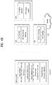
- FIG. 10 is a conceptual diagram handling for an uplink split operation in wireless communication system according to embodiments of the present invention.
- FIG. 11 is an example for handling for an uplink split operation in wireless communication system according to embodiments of the present invention.
- Universal mobile telecommunications system is a 3rd Generation (3G) asynchronous mobile communication system operating in wideband code division multiple access (WCDMA) based on European systems, global system for mobile communications (GSM) and general packet radio services (GPRS).
- 3G 3rd Generation
- WCDMA wideband code division multiple access
- GSM global system for mobile communications
- GPRS general packet radio services
- LTE long-term evolution
- 3GPP 3rd generation partnership project
- the 3GPP LTE is a technology for enabling high-speed packet communications. Many schemes have been proposed for the LTE objective including those that aim to reduce user and provider costs, improve service quality, and expand and improve coverage and system capacity.
- the 3G LTE requires reduced cost per bit, increased service availability, flexible use of a frequency band, a simple structure, an open interface, and adequate power consumption of a terminal as an upper-level requirement.
- LTE long term evolution
- LTE-A LTE-advanced
- TDD time division duplex
- FIG. 2A is a block diagram illustrating network structure of an evolved universal mobile telecommunication system (E-UMTS).
- E-UMTS may be also referred to as an LTE system.
- the communication network is widely deployed to provide a variety of communication services such as voice (VoIP) through IMS and packet data.
- VoIP voice
- IMS packet data
- the E-UMTS network includes an evolved UMTS terrestrial radio access network (E-UTRAN), an Evolved Packet Core (EPC) and one or more user equipment.
- the E-UTRAN may include one or more evolved NodeB (eNodeB) 20 , and a plurality of user equipment (UE) 10 may be located in one cell.
- eNodeB evolved NodeB
- UE user equipment
- MME mobility management entity
- SAE gateways 30 may be positioned at the end of the network and connected to an external network.
- downlink refers to communication from eNodeB 20 to UE 10
- uplink refers to communication from the UE to an eNodeB
- UE 10 refers to communication equipment carried by a user and may be also referred to as a mobile station (MS), a user terminal (UT), a subscriber station (SS) or a wireless device.
- MS mobile station
- UT user terminal
- SS subscriber station
- FIG. 2B is a block diagram depicting architecture of a typical E-UTRAN and a typical EPC.
- an eNodeB 20 provides end points of a user plane and a control plane to the UE 10 .
- MME/SAE gateway 30 provides an end point of a session and mobility management function for UE 10 .
- the eNodeB and MME/SAE gateway may be connected via an S1 interface.
- the eNodeB 20 is generally a fixed station that communicates with a UE 10 , and may also be referred to as a base station (BS) or an access point.
- BS base station
- One eNodeB 20 may be deployed per cell.
- An interface for transmitting user traffic or control traffic may be used between eNodeBs 20 .
- the MME provides various functions including NAS signaling to eNodeBs 20 , NAS signaling security, AS Security control, Inter CN node signaling for mobility between 3GPP access networks, Idle mode UE Reachability (including control and execution of paging retransmission), Tracking Area list management (for UE in idle and active mode), PDN GW and Serving GW selection, MME selection for handovers with MME change, SGSN selection for handovers to 2G or 3G 3GPP access networks, Roaming, Authentication, Bearer management functions including dedicated bearer establishment, Support for PWS (which includes ETWS and CMAS) message transmission.
- the SAE gateway host provides assorted functions including Per-user based packet filtering (by e.g.
- MME/SAE gateway 30 will be referred to herein simply as a “gateway,” but it is understood that this entity includes both an MME and an SAE gateway.
- a plurality of nodes may be connected between eNodeB 20 and gateway 30 via the S1 interface.
- the eNodeBs 20 may be connected to each other via an X2 interface and neighboring eNodeBs may have a meshed network structure that has the X2 interface.
- eNodeB 20 may perform functions of selection for gateway 30 , routing toward the gateway during a Radio Resource Control (RRC) activation, scheduling and transmitting of paging messages, scheduling and transmitting of Broadcast Channel (BCCH) information, dynamic allocation of resources to UEs 10 in both uplink and downlink, configuration and provisioning of eNodeB measurements, radio bearer control, radio admission control (RAC), and connection mobility control in LTE_ACTIVE state.
- gateway 30 may perform functions of paging origination, LTE-IDLE state management, ciphering of the user plane, System Architecture Evolution (SAE) bearer control, and ciphering and integrity protection of Non-Access Stratum (NAS) signaling.
- SAE System Architecture Evolution
- NAS Non-Access Stratum
- the EPC includes a mobility management entity (MME), a serving-gateway (S-GW), and a packet data network-gateway (PDN-GW).
- MME mobility management entity
- S-GW serving-gateway
- PDN-GW packet data network-gateway
- FIG. 3 is a diagram showing a control plane and a user plane of a radio interface protocol between a UE and an E-UTRAN based on a 3GPP radio access network standard.
- the control plane refers to a path used for transmitting control messages used for managing a call between the UE and the E-UTRAN.
- the user plane refers to a path used for transmitting data generated in an application layer, e.g., voice data or Internet packet data.
- a physical (PHY) layer of a first layer provides an information transfer service to a higher layer using a physical channel.
- the PHY layer is connected to a medium access control (MAC) layer located on the higher layer via a transport channel.
- Data is transported between the MAC layer and the PHY layer via the transport channel.
- Data is transported between a physical layer of a transmitting side and a physical layer of a receiving side via physical channels.
- the physical channels use time and frequency as radio resources.
- the physical channel is modulated using an orthogonal frequency division multiple access (OFDMA) scheme in downlink and is modulated using a single carrier frequency division multiple access (SC-FDMA) scheme in uplink.
- OFDMA orthogonal frequency division multiple access
- SC-FDMA single carrier frequency division multiple access
- the MAC layer of a second layer provides a service to a radio link control (RLC) layer of a higher layer via a logical channel.
- the RLC layer of the second layer supports reliable data transmission.
- a function of the RLC layer may be implemented by a functional block of the MAC layer.
- a packet data convergence protocol (PDCP) layer of the second layer performs a header compression function to reduce unnecessary control information for efficient transmission of an Internet protocol (IP) packet such as an IP version 4 (IPv4) packet or an IP version 6 (IPv6) packet in a radio interface having a relatively small bandwidth.
- IP Internet protocol
- IPv4 IP version 4
- IPv6 IP version 6
- a radio resource control (RRC) layer located at the bottom of a third layer is defined only in the control plane.
- the RRC layer controls logical channels, transport channels, and physical channels in relation to configuration, re-configuration, and release of radio bearers (RBs).
- An RB refers to a service that the second layer provides for data transmission between the UE and the E-UTRAN.
- the RRC layer of the UE and the RRC layer of the E-UTRAN exchange RRC messages with each other.
- One cell of the eNB is set to operate in one of bandwidths such as 1.25, 2.5, 5, 10, 15, and 20 MHz and provides a downlink or uplink transmission service to a plurality of UEs in the bandwidth. Different cells may be set to provide different bandwidths.
- Downlink transport channels for transmission of data from the E-UTRAN to the UE include a broadcast channel (BCH) for transmission of system information, a paging channel (PCH) for transmission of paging messages, and a downlink shared channel (SCH) for transmission of user traffic or control messages.
- BCH broadcast channel
- PCH paging channel
- SCH downlink shared channel
- Traffic or control messages of a downlink multicast or broadcast service may be transmitted through the downlink SCH and may also be transmitted through a separate downlink multicast channel (MCH).
- MCH downlink multicast channel
- Uplink transport channels for transmission of data from the UE to the E-UTRAN include a random access channel (RACH) for transmission of initial control messages and an uplink SCH for transmission of user traffic or control messages.
- Logical channels that are defined above the transport channels and mapped to the transport channels include a broadcast control channel (BCCH), a paging control channel (PCCH), a common control channel (CCCH), a multicast control channel (MCCH), and a multicast traffic channel (MTCH).
- BCCH broadcast control channel
- PCCH paging control channel
- CCCH common control channel
- MCCH multicast control channel
- MTCH multicast traffic channel
- FIG. 4A is a block diagram illustrating network structure of NG Radio Access Network (NG-RAN) architecture
- FIG. 4B is a block diagram depicting architecture of functional Split between NG-RAN and 5G Core Network (5GC).
- NG-RAN NG Radio Access Network
- 5GC 5G Core Network
- An NG-RAN node is a gNB, providing NR user plane and control plane protocol terminations towards the UE, or an ng-eNB, providing E-UTRA user plane and control plane protocol terminations towards the UE.
- the gNBs and ng-eNBs are interconnected with each other by means of the Xn interface.
- the gNBs and ng-eNBs are also connected by means of the NG interfaces to the 5GC, more specifically to the AMF (Access and Mobility Management Function) by means of the NG-C interface and to the UPF (User Plane Function) by means of the NG-U interface.
- AMF Access and Mobility Management Function
- UPF User Plane Function
- the Xn Interface includes Xn user plane (Xn-U), and Xn control plane (Xn-C).
- the Xn User plane (Xn-U) interface is defined between two NG-RAN nodes.
- the transport network layer is built on IP transport and GTP-U is used on top of UDP/IP to carry the user plane PDUs.
- Xn-U provides non-guaranteed delivery of user plane PDUs and supports the following functions: i) Data forwarding, and ii) Flow control.
- the Xn control plane interface (Xn-C) is defined between two NG-RAN nodes.
- the transport network layer is built on SCTP on top of IP.
- the application layer signalling protocol is referred to as XnAP (Xn Application Protocol).
- the SCTP layer provides the guaranteed delivery of application layer messages.
- point-to-point transmission is used to deliver the signalling PDUs.
- the Xn-C interface supports the following functions: i) Xn interface management, ii) UE mobility management, including context transfer and RAN paging, and iii) Dual connectivity.
- the NG Interface includes NG User Plane (NG-U) and NG Control Plane (NG-C).
- NG-U NG User Plane
- NG-C NG Control Plane
- the NG user plane interface (NG-U) is defined between the NG-RAN node and the UPF.
- the transport network layer is built on IP transport and GTP-U is used on top of UDP/IP to carry the user plane PDUs between the NG-RAN node and the UPF.
- NG-U provides non-guaranteed delivery of user plane PDUs between the NG-RAN node and the UPF.
- the NG control plane interface (NG-C) is defined between the NG-RAN node and the AMF.
- the transport network layer is built on IP transport.
- SCTP is added on top of IP.
- the application layer signalling protocol is referred to as NGAP (NG Application Protocol).
- NGAP NG Application Protocol
- the SCTP layer provides guaranteed delivery of application layer messages.
- IP layer point-to-point transmission is used to deliver the signalling PDUs.
- NG-C provides the following functions: i) NG interface management, ii) UE context management, iii) UE mobility management, iv) Configuration Transfer, and v) Warning Message Transmission.
- the gNB and ng-eNB host the following functions: i) Functions for Radio Resource Management: Radio Bearer Control, Radio Admission Control, Connection Mobility Control, Dynamic allocation of resources to UEs in both uplink and downlink (scheduling), ii) IP header compression, encryption and integrity protection of data, iii) Selection of an AMF at UE attachment when no routing to an AMF can be determined from the information provided by the UE, iv) Routing of User Plane data towards UPF(s), v) Routing of Control Plane information towards AMF, vi) Connection setup and release, vii) Scheduling and transmission of paging messages (originated from the AMF), viii) Scheduling and transmission of system broadcast information (originated from the AMF or O&M), ix) Measurement and measurement reporting configuration for mobility and scheduling, x) Transport level packet marking in the uplink, xi) Session Management, xii) Support of Network Slicing, and xiii) QoS Flow management
- the Access and Mobility Management Function hosts the following main functions: i) NAS signalling termination, ii) NAS signalling security, iii) AS Security control, iv) Inter CN node signalling for mobility between 3GPP access networks, v) Idle mode UE Reachability (including control and execution of paging retransmission), vi) Registration Area management, vii) Support of intra-system and inter-system mobility, viii) Access Authentication, ix) Mobility management control (subscription and policies), x) Support of Network Slicing, and xi) SMF selection.
- the User Plane Function hosts the following main functions: i) Anchor point for Intra-/Inter-RAT mobility (when applicable), ii) External PDU session point of interconnect to Data Network, iii) Packet inspection and User plane part of Policy rule enforcement, iv) Traffic usage reporting, v) Uplink classifier to support routing traffic flows to a data network, vi) QoS handling for user plane, e.g. packet filtering, gating, UL/DL rate enforcement, and vii) Uplink Traffic verification (SDF to QoS flow mapping).
- SDF Uplink Traffic verification
- the Session Management function hosts the following main functions: i) Session Management, ii) UE IP address allocation and management, iii) Selection and control of UP function, iv) Configures traffic steering at UPF to route traffic to proper destination, v) Control part of policy enforcement and QoS, vi) Downlink Data Notification.
- FIG. 5 is a diagram showing a control plane and a user plane of a radio interface protocol between a UE and a NG-RAN based on a 3rd generation partnership project (3GPP) radio access network standard.
- 3GPP 3rd generation partnership project
- the user plane protocol stack contains Phy, MAC, RLC, PDCP and SDAP (Service Data Adaptation Protocol) which is newly introduced to support 5G QoS model.
- the main services and functions of SDAP entity include i) Mapping between a QoS flow and a data radio bearer, and ii) Marking QoS flow ID (QFI) in both DL and UL packets.
- QFI QoS flow ID
- the transmitting SDAP entity may map the SDAP SDU to the default DRB if there is no stored QoS flow to DRB mapping rule for the QoS flow. If there is a stored QoS flow to DRB mapping rule for the QoS flow, the SDAP entity may map the SDAP SDU to the DRB according to the stored QoS flow to DRB mapping rule. And the SDAP entity may construct the SDAP PDU and deliver the constructed SDAP PDU to the lower layers.
- FIG. 6 is a block diagram of a communication apparatus according to an embodiment of the present invention.
- the apparatus shown in FIG. 6 can be a user equipment (UE) and/or eNB or gNB adapted to perform the above mechanism, but it can be any apparatus for performing the same operation.
- UE user equipment
- the apparatus may comprises a DSP/microprocessor ( 110 ) and RF module (transmiceiver; 135 ).
- the DSP/microprocessor ( 110 ) is electrically connected with the transciver ( 135 ) and controls it.
- the apparatus may further include power management module ( 105 ), battery ( 155 ), display ( 115 ), keypad ( 120 ), SIM card ( 125 ), memory device ( 130 ), speaker ( 145 ) and input device ( 150 ), based on its implementation and designer's choice.
- FIG. 6 may represent a UE comprising a receiver ( 135 ) configured to receive a request message from a network, and a transmitter ( 135 ) configured to transmit the transmission or reception timing information to the network. These receiver and the transmitter can constitute the transceiver ( 135 ).
- the UE further comprises a processor ( 110 ) connected to the transceiver ( 135 : receiver and transmitter).
- FIG. 6 may represent a network apparatus comprising a transmitter ( 135 ) configured to transmit a request message to a UE and a receiver ( 135 ) configured to receive the transmission or reception timing information from the UE. These transmitter and receiver may constitute the transceiver ( 135 ).
- the network further comprises a processor ( 110 ) connected to the transmitter and the receiver. This processor ( 110 ) may be configured to calculate latency based on the transmission or reception timing information.
- FIG. 7 is examples for radio bearers supporting UL split operation in LTE and NR system.
- FIG. 7A is a diagram for Radio Protocol Architecture for Dual Connectivity (DC).
- DC Radio Protocol Architecture for Dual Connectivity
- MCG bearer Three bearer types exist: MCG bearer, SCG bearer and split bearer. Those three bearer types are depicted on FIG. 7A .
- RRC is located in MeNB and SRBs are always configured as MCG bearer type and therefore only use the radio resources of the MeNB.
- S1-U connection to the S-GW is terminated in the MeNB.
- PDCP data is transferred between the MeNB and the SeNB via X2-U.
- the SeNB and MeNB are involved in transmitting data of this bearer type over the Uu.
- FIG. 7B is a diagram for LWA Radio Protocol Architecture for the Collocated Scenario.
- LWA LTE-WLAN Aggregation
- the radio protocol architecture that a particular bearer uses depends on the LWA backhaul scenario and how the bearer is set up.
- FIG. 7B is for the collocated scenario.
- LWA supports split bearer operation where the PDCP sublayer supports in-sequence delivery of upper layer PDUs based on the reordering procedure introduced for DC.
- FIG. 7C is a diagram for Radio Protocol Architecture for MCG, SCG and split bearers from a UE perspective in MR-DC with EPC (EN-DC)
- FIG. 7D is a diagram for Radio Protocol Architecture for MCG, SCG and split bearers from a UE perspective in MR-DC with 5GC (NGEN-DC, NE-DC).
- MCG bearer MCG bearer
- SCG bearer SCG bearer
- split bearer MCG bearer
- FIG. 7C depicted in FIG. 7C for MR-DC with EPC (EN-DC) and in FIG. 7D for MR-DC with 5GC (NGEN-DC, NE-DC).
- the network can configure either E-UTRA PDCP or NR PDCP for MCG bearers while NR PDCP is always used for SCG and split bearers.
- NR PDCP In MR-DC with 5GC, NR PDCP is always used for all bearer types.
- E-UTRA RLC/MAC In NGEN-DC, E-UTRA RLC/MAC is used in the MN while NR RLC/MAC is used in the SN.
- NR RLC/MAC In NE-DC, NR RLC/MAC is used in the MN while E-UTRA RLC/MAC is used in the SN.
- FIG. 7E is a diagram for Network side protocol termination options for MCG, SCG and split bearers in MR-DC with EPC (EN-DC)
- FIG. 7F is a diagram for Network side protocol termination options for MCG, SCG and split bearers in MR-DC with 5GC (NGEN-DC, NE-DC).
- split bearer structures mentioned above have common in that a transmitting PDCP entity is associated with two RLC entities. Since one PDCP entity and two RLC entities are configured for a radio bearer, and each of RLC entities is associated with a respective MAC entity, we discussed how to deal with PDCP data volumes in the past in the UL split operation.
- FIG. 8 is an example for operation using LTE threshold based approach for uplink split bearer.
- the PDCP entity indicates PDCP data volume to a MAC entity when there is change in PDCP data volume (or every TTI). Based on the change in PDCP data volume, the MAC entity may trigger BSR if triggering condition is met, e.g. if PDCP data volume is changed from 0 to finite value.
- the PDCP entity For UL split bearers in Rel-12 of 3GPP, the PDCP entity indicates the PDCP data volume to only one MAC entity depending on the configuration (ul-DataSplitDRB-ViaSCG). For the other MAC entity, the PDCP entity does not indicate PDCP data volume at all. If the total amount of PDCP data volume is equal to or larger than ul-DataSplitThreshold, the PDCP entity indicate the PDCP data volume to both the MAC entity configured for SCG and the MAC entity configured for MCG.
- a threshold based approach is used in uplink data transmission and buffer status reporting.
- the UE is configured with a threshold (ul-DataSplitThreshold), and the PDCP entity compares the amount of data available for transmission in the PDCP entity with the threshold.
- the PDCP entity performs comparison when the PDCP entity is requested to submit PDCP PDUs from lower layers. If amount of PDCP data exceeds the threshold, the PDCP entity submits the PDCP PDU to either RLC entity for MCG or SCG. Otherwise if amount of PDCP data doesn't exceed the threshold, the PDCP entity submits the PDCP PDU to one RLC entity which is configured by the eNB (ul-DataSplitDRB-ViaSCG).
- the PDCP entity indicates the PDCP data volume to a MAC entity configured for SCG, only if ul-DataSplitDRB-ViaSCG is set to TRUE by upper layer, while the PDCP entity indicates the PDCP data volume as 0 to the MAC entity configured for MCG.
- the PDCP entity indicates the PDCP data volume to the MAC entity. If ul-LWA-DataSplitThreshold is configured and the PDCP data volume is less than or ul-LWA-DataSplitThreshold, the PDCP entity indicates the PDCP data volume as 0 to the MAC entity if ul-LWA-DRB-ViaWLAN is set to TRUE by upper layers. Else, the PDCP entity indicates the PDCP data volume to the MAC entity. For LWA bearers, only the data that may be sent over LTE (i.e., excluding UL data already sent or decided to be sent over WLAN) is considered as “data available for transmission”.
- the PDCP entity uses both paths only if PDCP data volume is high while using one configured path if PDCP data volume is low.
- the reason of using PDCP data volume as a threshold is to use both paths when many PDCP data is arrived at the PDCP entity considering that using one path is sufficient when there is not many PDCP data arriving at the PDCP entity.
- FIG. 9 is an example for pre-processing with threshold based approach.
- NR there are some agreements in the UL split operation.
- pre-processing is an important key to consider when designing a Layer 2 protocol. In this sense, it was agreed that RLC concatenation is removed and RLC delivers out-of sequence RLC SDU to upper layer.
- LTE threshold based approach may prevent use of two uplink paths when pre-processing is performed in the PDCP entity.
- LTE threshold based approach would mean that the PDCP entity compares the amount of PDCP data to the threshold when the PDCP entity performs pre-processing even before the PDCP entity is requested to deliver PDCP PDUs. If the PDCP entity performs pre-processing frequently, e.g., for every PDCP SDU reception, the amount of PDCP data is not likely to exceed the threshold. Accordingly, the PDCP entity would submit the PDCP SDU always to one path.
- PDCP data volume is increasing and becomes larger than the threshold, the PDCP entity starts to use both paths. Then, PDCP data volume would soon become less than the threshold. Accordingly, the PDCP entity starts to use one path. As soon as the PDCP entity starts to use one path, it is likely that PDCP data volume exceeds the threshold again. In summary, PDCP data volume is frequently alternating above threshold and below threshold. We consider that this frequent change of PDCP data volume around the threshold would make the network scheduling more complex. Once the gNB/eNB is reported the buffer size from the UE, the gNB/eNB would schedule the UE.
- the UL grant may not be used by the the PDCP entity if PDCP data volume becomes less than the threshold due to UL grant from other gNB/eNB.
- the UE may trigger BSR because PDCP data is considered to become available for the path which has not be used previously.
- FIG. 10 is a conceptual diagram handling for an uplink split operation in wireless communication system according to embodiments of the present invention.
- the PDCP entity is configured with two thresholds, i.e., TH1 and TH2, (TH1 is less than TH2), where one is for condition to start using two paths while the other one is for condition to start using one path.
- this idea is different from the previous art in that the amount of the first data, was transmitted immediately before the second data, is considered when determining a path in which the second data is to be transmitted.
- the PDCP entity When first PDCP data becomes available for transmission in a PDCP entity, the PDCP entity indicates first data volume to a first and/or a second MAC entities. The UE determines a path where the first PDCP data is submitted based on the first data volume if there is no data available for transmission in the PDCP entity.
- the PDCP is configured with two different thresholds, i.e., TH1 and TH2, where TH1 is less than TH2.
- the transmitting PDCP entity shall consider the following as PDCP data volume: i) PDCP SDUs for which no PDCP Data PDUs have been constructed, ii) PDCP Data PDUs that have not been submitted to lower layers, and iii) PDCP Control PDUs. So, when the PDCP entity generates data (i.e. PDCP Control PDUs), and receives data (i.e. PDCP SDUs received from upper layers), the data becomes available for transmission in the PDCP entity.
- PDCP data volume i) PDCP SDUs for which no PDCP Data PDUs have been constructed, ii) PDCP Data PDUs that have not been submitted to lower layers, and iii) PDCP Control PDUs. So, when the PDCP entity generates data (i.e. PDCP Control PDUs), and receives data (i.e. PDCP SDUs received from upper layers), the data becomes available for transmission in the PDCP entity.
- the first data volume includes an amount of the PDCP data available for transmission and RLC data volume pending for initial transmission in the two associated RLC entities if pre-processing is configured for the PDCP entity.
- the UE should minimize the amount of PDCP PDUs submitted to lower layers before receiving request from lower layers and minimize the PDCP SN gap between PDCP PDUs submitted to two associated RLC entities to minimize PDCP reordering delay in the receiving PDCP entity.
- the method of determining an initial path for submitting the first data is the same as the legacy operation. It is advantageous for the UE to set a legacy TH used for determining the path to TH1.
- the initial path is a path to be used to submit initial data, when the first PDCP data becomes available for transmission from zero.
- the PDCP entity use a path for submitting the first PDCP data. So, the UE indicates the PDCP data volume to a MAC entity associated with the primary RLC entity when indicating the PDCP data volume to a MAC entity for BSR triggering and Buffer Size calculation, and the UE submits the first PDCP data to the primary RLC entity.
- the PDCP entity use all paths for submitting the first PDCP data. So, the UE indicates the PDCP data volume to both the MAC entity associated with the primary RLC entity and the MAC entity associated with the secondary RLC entity when indicating the PDCP data volume to a MAC entity for BSR triggering and Buffer Size calculation, and the UE submits the first PDCP data to either the primary RLC entity or the secondary RLC entity.
- the other method of determining an initial path is advantageous for the eNB. This method is to set a legacy TH used for determining the path to TH2.
- the PDCP entity use a path for submitting the first PDCP data. So, the UE indicates the PDCP data volume to a MAC entity associated with the primary RLC entity when indicating the PDCP data volume to a MAC entity for BSR triggering and Buffer Size calculation, and the UE submits the first PDCP data to the primary RLC entity.
- the PDCP entity use all paths for submitting the first PDCP data. So, the UE indicates the PDCP data volume to both the MAC entity associated with the primary RLC entity and the MAC entity associated with the secondary RLC entity when indicating the PDCP data volume to a MAC entity for BSR triggering and Buffer Size calculation, and the UE submits the first PDCP data to either the primary RLC entity or the secondary RLC entity.
- the UE determines a second data volume for indicating the second data volume to the first MAC entity and/or a second MAC entity after indicating the first data volume to the first MAC entity and/or the second MAC entity (S 1001 ).
- the transmitting PDCP entity shall consider the following as PDCP data volume: i) PDCP SDUs for which no PDCP Data PDUs have been constructed, ii) PDCP Data PDUs that have not been submitted to lower layers, and iii) PDCP Control PDUs. So, when the PDCP entity generates data (i.e. PDCP Control PDUs), and receives data (i.e. PDCP SDUs received from upper layers), the data becomes available for transmission in the PDCP entity.
- PDCP data volume i) PDCP SDUs for which no PDCP Data PDUs have been constructed, ii) PDCP Data PDUs that have not been submitted to lower layers, and iii) PDCP Control PDUs. So, when the PDCP entity generates data (i.e. PDCP Control PDUs), and receives data (i.e. PDCP SDUs received from upper layers), the data becomes available for transmission in the PDCP entity.
- the second data volume includes amount of the PDCP data available for transmission and RLC data volume pending for initial transmission in the two associated RLC entities if pre-processing is configured for the PDCP entity.
- the PDCP entity use a path for submitting the second PDCP data according to legacy mechanism (S 1003 ). So, the UE indicates the PDCP data volume to a MAC entity associated with the primary RLC entity when indicating the PDCP data volume to a MAC entity for BSR triggering and Buffer Size calculation, and the UE submits the first PDCP data to the primary RLC entity.
- the PDCP entity use two paths for submitting the second PDCP data according to legacy mechanism (S 1005 ). So, the UE indicates the PDCP data volume to both the MAC entity associated with the primary RLC entity and the MAC entity associated with the secondary RLC entity when indicating the PDCP data volume to a MAC entity for BSR triggering and Buffer Size calculation, and the UE submits the first PDCP data to either the primary RLC entity or the secondary RLC entity.
- Our invention proposes that if the second data volume becomes larger than TH1 but smaller than TH2, the PDCP entity changes to use either one path or two paths depending on whether the first PDCP data volume is smaller than TH1 or larger than TH2.
- the UE can keep using the previous path when determining a RLC entity to be used for submitting the second data based on first data volume.
- the UE keeps using one path (S 1007 ).
- the one path which is associated with a primary RLC entity, is configured by a network via RRC signaling.
- the primary RLC entity operates for a Master Node for dual connectivity.
- PDCP data volume is indicated to a MAC entity associated with the primary RLC entity, and iii) PDCP data is submitted to the primary RLC entity.
- the PDCP entity indicates the PDCP data volume to a MAC entity associated with the primary RLC entity when indicating the PDCP data volume to a MAC entity for BSR triggering and Buffer Size calculation, and the UE submits the first PDCP data to the primary RLC entity.
- the UE keeps using all/both paths (S 1009 ).
- the PDCP decides to keep using all/both paths: i) PDCP data volume is indicated to all MAC entities associated with all RLC entities, and ii) PDCP data is submitted to one of RLC entities.
- the UE indicates the PDCP data volume to both the MAC entity associated with the primary RLC entity and the MAC entity associated with the secondary RLC entity when indicating the PDCP data volume to a MAC entity for BSR triggering and Buffer Size calculation, and the UE submits the first PDCP data to either the primary RLC entity or the secondary RLC entity.
- the first MAC entity when a first MAC entity associated with the primary RLC entity receives the indication indicating PDCP data volume, the first MAC entity triggers a buffer status reporting if the second data belongs to a logical channel with higher priority than the priorities of the logical channels which belong to any LCG and for which data is already available for transmission. Otherwise, when a second MAC entity associated with the secondary RLC entity receives the indication indicating PDCP data volume, the second MAC entity triggers a buffer status reporting if the second data belongs to a logical channel with higher priority than the priorities of the logical channels which belong to any LCG and for which data is already available for transmission.
- the first MAC entity When the first MAC entity triggers a buffer status reporting, the first MAC entity the triggered buffer status reporting to a first base station for the first MAC entity. And when the second MAC entity triggers a buffer status reporting, the second MAC entity the triggered buffer status reporting to a second base station for the second MAC entity.
- the PDCP data is transmitted to a first base station for the primary RLC entity.
- the PDCP data is transmitted to a second base station for the secondary RLC entity.
- FIG. 11 is an example for handling for an uplink split operation in wireless communication system according to embodiments of the present invention.
- the PDCP entity determines using all paths of the split bearer.
- PDCP data volume becomes a value which is larger than TH1 but smaller than TH2, from a value which is larger than TH2 (B), the PDCP entity keeps using all paths of the split bearer.
- the PDCP entity determines using one path of the split bearer.
- the one path which is associated with a primary RLC entity, is configured by a network via RRC signaling.
- the primary RLC entity operates for a Master Node for dual connectivity.
- PDCP data volume is indicated to a MAC entity associated with the primary RLC entity, and
- PDCP data is submitted to the primary RLC entity.
- PDCP data volume is indicated to all MAC entities associated with all RLC entities, and ii) PDCP data is submitted to one of RLC entities.
- a specific operation described as performed by the BS may be performed by an upper node of the BS. Namely, it is apparent that, in a network comprised of a plurality of network nodes including a BS, various operations performed for communication with an MS may be performed by the BS, or network nodes other than the BS.
- the term ‘eNB’ may be replaced with the term ‘fixed station’, ‘Node B’, ‘Base Station (BS)’, ‘access point’, etc.
- the method according to the embodiments of the present invention may be implemented by one or more Application Specific Integrated Circuits (ASICs), Digital Signal Processors (DSPs), Digital Signal Processing Devices (DSPDs), Programmable Logic Devices (PLDs), Field Programmable Gate Arrays (FPGAs), processors, controllers, microcontrollers, or microprocessors.
- ASICs Application Specific Integrated Circuits
- DSPs Digital Signal Processors
- DSPDs Digital Signal Processing Devices
- PLDs Programmable Logic Devices
- FPGAs Field Programmable Gate Arrays
- processors controllers, microcontrollers, or microprocessors.
- the method according to the embodiments of the present invention may be implemented in the form of modules, procedures, functions, etc. performing the above-described functions or operations.
- Software code may be stored in a memory unit and executed by a processor.
- the memory unit may be located at the interior or exterior of the processor and may transmit and receive data to and from the processor via various known means.
Abstract
Description
Claims (14)
Priority Applications (1)
| Application Number | Priority Date | Filing Date | Title |
|---|---|---|---|
| US16/100,739 US10785778B2 (en) | 2017-08-12 | 2018-08-10 | Method for handling for an uplink split operation in wireless communication system and a device therefor |
Applications Claiming Priority (2)
| Application Number | Priority Date | Filing Date | Title |
|---|---|---|---|
| US201762544777P | 2017-08-12 | 2017-08-12 | |
| US16/100,739 US10785778B2 (en) | 2017-08-12 | 2018-08-10 | Method for handling for an uplink split operation in wireless communication system and a device therefor |
Publications (2)
| Publication Number | Publication Date |
|---|---|
| US20190069308A1 US20190069308A1 (en) | 2019-02-28 |
| US10785778B2 true US10785778B2 (en) | 2020-09-22 |
Family
ID=65435911
Family Applications (1)
| Application Number | Title | Priority Date | Filing Date |
|---|---|---|---|
| US16/100,739 Active 2038-10-11 US10785778B2 (en) | 2017-08-12 | 2018-08-10 | Method for handling for an uplink split operation in wireless communication system and a device therefor |
Country Status (1)
| Country | Link |
|---|---|
| US (1) | US10785778B2 (en) |
Families Citing this family (14)
| Publication number | Priority date | Publication date | Assignee | Title |
|---|---|---|---|---|
| US10237784B2 (en) * | 2017-03-24 | 2019-03-19 | Motorola Mobility Llc | Split bearer packet data converge protocol protocol data unit routing |
| WO2018212535A1 (en) * | 2017-05-16 | 2018-11-22 | Lg Electronics Inc. | Apparatus and method for a user equipment (ue) operating a split bearer |
| CN111132375B (en) * | 2018-10-31 | 2021-09-10 | 维沃移动通信有限公司 | Control method for separated load bearing and related equipment |
| EP3723444A1 (en) | 2019-04-12 | 2020-10-14 | Samsung Electronics Co., Ltd. | Electronic device supporting dual connectivity and method of operating the same |
| AU2019442498A1 (en) * | 2019-04-26 | 2021-05-06 | Guangdong Oppo Mobile Telecommunications Corp., Ltd. | Method or device for integrity protection |
| KR20210009730A (en) * | 2019-07-17 | 2021-01-27 | 삼성전자주식회사 | Electronic device for transmitting data by using split bearer and method for the same |
| KR20210009734A (en) * | 2019-07-17 | 2021-01-27 | 삼성전자주식회사 | Electronic device for transmitting data by using split bearer and method for the same |
| US11546968B2 (en) | 2019-08-15 | 2023-01-03 | Apple Inc. | Traffic-rate based branch deactivation for UE power efficiency in a dual-connectivity mode |
| WO2021030970A1 (en) * | 2019-08-16 | 2021-02-25 | Qualcomm Incorporated | Ul transmission method for endc dual connection device |
| US11323983B2 (en) * | 2019-10-01 | 2022-05-03 | Qualcomm Incorporated | Efficient usage of resources in an uplink split bearer configuration |
| WO2021188852A1 (en) * | 2020-03-20 | 2021-09-23 | Nokia Technologies Oy | Ue-based energy efficient uplink data split in dual connectivity |
| CN113453274B (en) * | 2020-03-25 | 2023-03-03 | 华为技术有限公司 | Uplink data distribution method and terminal |
| CN114339877A (en) * | 2020-09-30 | 2022-04-12 | 展讯通信(上海)有限公司 | BSR (buffer status report) triggering method of relay and related product |
| WO2023115301A1 (en) * | 2021-12-21 | 2023-06-29 | Oppo广东移动通信有限公司 | Data transmission method and apparatus, and computer device and storage medium |
Citations (12)
| Publication number | Priority date | Publication date | Assignee | Title |
|---|---|---|---|---|
| US20090190554A1 (en) * | 2008-01-25 | 2009-07-30 | Cho Yoon Jung | Method for performing handover procedure and creating data |
| US20100118781A1 (en) * | 2007-04-20 | 2010-05-13 | Panasonic Corporation | Transmission Scheme of Protocol Data Units During a Procedure That Comprises the Reset of the Protocol Layer |
| US20120275381A1 (en) * | 2009-12-11 | 2012-11-01 | Samsung Electronics Co. Ltd. | Method and apparatus for performing contention-based access in a mobile communication system |
| US20130242859A1 (en) * | 2012-03-17 | 2013-09-19 | Zahide Ozlem Celik | Handling Packet Data Convergence Protocol Data Units |
| US20150181461A1 (en) * | 2012-05-21 | 2015-06-25 | Samsung Electronics Co., Ltd. | Method and device for transmitting and receiving data in mobile communication system |
| US20160037526A1 (en) * | 2013-09-27 | 2016-02-04 | Samsung Electronics Co., Ltd | Method and apparatus for transmitting and receiving data using plurality of carriers in mobile communication system |
| US20160249232A1 (en) * | 2013-10-31 | 2016-08-25 | Ntt Docomo, Inc. | User equipment and method |
| US20160286429A1 (en) * | 2013-11-11 | 2016-09-29 | Zte Corporation | BSR reporting method, Evolved Node B, UE and computer storage medium |
| US20170111927A1 (en) * | 2014-03-21 | 2017-04-20 | Samsung Electronics Co., Ltd | Method and apparatus for reporting buffer state by user equipment in communication system |
| US20170135151A1 (en) * | 2014-07-24 | 2017-05-11 | Kyocera Corporation | User terminal, communication control method and chipset |
| US20180027443A1 (en) * | 2015-03-30 | 2018-01-25 | Lg Electronics Inc. | Method for performing a buffer status reporting in a wireless communication system and device therefor |
| US20180352468A1 (en) * | 2016-01-08 | 2018-12-06 | Nec Corporation | Radio station system, radio terminal, and methods therein |
-
2018
- 2018-08-10 US US16/100,739 patent/US10785778B2/en active Active
Patent Citations (12)
| Publication number | Priority date | Publication date | Assignee | Title |
|---|---|---|---|---|
| US20100118781A1 (en) * | 2007-04-20 | 2010-05-13 | Panasonic Corporation | Transmission Scheme of Protocol Data Units During a Procedure That Comprises the Reset of the Protocol Layer |
| US20090190554A1 (en) * | 2008-01-25 | 2009-07-30 | Cho Yoon Jung | Method for performing handover procedure and creating data |
| US20120275381A1 (en) * | 2009-12-11 | 2012-11-01 | Samsung Electronics Co. Ltd. | Method and apparatus for performing contention-based access in a mobile communication system |
| US20130242859A1 (en) * | 2012-03-17 | 2013-09-19 | Zahide Ozlem Celik | Handling Packet Data Convergence Protocol Data Units |
| US20150181461A1 (en) * | 2012-05-21 | 2015-06-25 | Samsung Electronics Co., Ltd. | Method and device for transmitting and receiving data in mobile communication system |
| US20160037526A1 (en) * | 2013-09-27 | 2016-02-04 | Samsung Electronics Co., Ltd | Method and apparatus for transmitting and receiving data using plurality of carriers in mobile communication system |
| US20160249232A1 (en) * | 2013-10-31 | 2016-08-25 | Ntt Docomo, Inc. | User equipment and method |
| US20160286429A1 (en) * | 2013-11-11 | 2016-09-29 | Zte Corporation | BSR reporting method, Evolved Node B, UE and computer storage medium |
| US20170111927A1 (en) * | 2014-03-21 | 2017-04-20 | Samsung Electronics Co., Ltd | Method and apparatus for reporting buffer state by user equipment in communication system |
| US20170135151A1 (en) * | 2014-07-24 | 2017-05-11 | Kyocera Corporation | User terminal, communication control method and chipset |
| US20180027443A1 (en) * | 2015-03-30 | 2018-01-25 | Lg Electronics Inc. | Method for performing a buffer status reporting in a wireless communication system and device therefor |
| US20180352468A1 (en) * | 2016-01-08 | 2018-12-06 | Nec Corporation | Radio station system, radio terminal, and methods therein |
Also Published As
| Publication number | Publication date |
|---|---|
| US20190069308A1 (en) | 2019-02-28 |
Similar Documents
| Publication | Publication Date | Title |
|---|---|---|
| US10785778B2 (en) | Method for handling for an uplink split operation in wireless communication system and a device therefor | |
| US10972935B2 (en) | Method for performing reflective quality of service (QoS) in wireless communication system and a device therefor | |
| US11032740B2 (en) | Method for performing a re-establishment of a PDCP entity associated with UM RLC entity in wireless communication system and a device therefor | |
| US11115855B2 (en) | Method for transmitting UL packet based on quality of service (QoS) flow in wireless communication system and a device therefor | |
| US10601535B2 (en) | Method for performing SCG re-establishment in dual connectivity in wireless communication system and a device therefor | |
| US10680967B2 (en) | Method for handling state variables of a PDCP entity in wireless communication system and a device therefor | |
| US11343703B2 (en) | Method for performing reflective quality of service in wireless communication system and a device therefor | |
| EP3603168B1 (en) | Method for transmitting lossless data packet based on quality of service (qos) framework in wireless communication system and a device therefor | |
| US11212669B2 (en) | Method for handling of a prohibit timer to transmit a RRC message related to UE capability restriction in wireless communication system and a device therefor | |
| US11019527B2 (en) | Method for transmitting TCP ACK packet in wireless communication system and a device therefor | |
| US11160119B2 (en) | Method for requesting an uplink resource in a wireless communication system and a device therefor | |
| US11297638B2 (en) | Method for triggering a buffer status reporting in wireless communication system and a device therefor | |
| US11160107B2 (en) | Method for performing a LCP procedure in wireless communication system and a device therefor | |
| US11190977B2 (en) | Method for handling data lossless in a UM RLC entity in wireless communication system and a device therefor | |
| US11363624B2 (en) | Method for receiving DL data on SPS resources in wireless communication system and a device therefor | |
| EP3689078B1 (en) | Method for transmitting uplink data which is robust to collision on shared uplink resource in wireless communication system and a device therefor |
Legal Events
| Date | Code | Title | Description |
|---|---|---|---|
| AS | Assignment |
Owner name: LG ELECTRONICS INC., KOREA, REPUBLIC OF Free format text: ASSIGNMENT OF ASSIGNORS INTEREST;ASSIGNORS:LEE, SUNYOUNG;YI, SEUNGJUNE;REEL/FRAME:046618/0946 Effective date: 20180807 |
|
| FEPP | Fee payment procedure |
Free format text: ENTITY STATUS SET TO UNDISCOUNTED (ORIGINAL EVENT CODE: BIG.); ENTITY STATUS OF PATENT OWNER: LARGE ENTITY |
|
| STPP | Information on status: patent application and granting procedure in general |
Free format text: DOCKETED NEW CASE - READY FOR EXAMINATION |
|
| STPP | Information on status: patent application and granting procedure in general |
Free format text: NON FINAL ACTION MAILED |
|
| STPP | Information on status: patent application and granting procedure in general |
Free format text: RESPONSE TO NON-FINAL OFFICE ACTION ENTERED AND FORWARDED TO EXAMINER |
|
| STPP | Information on status: patent application and granting procedure in general |
Free format text: NOTICE OF ALLOWANCE MAILED -- APPLICATION RECEIVED IN OFFICE OF PUBLICATIONS |
|
| STPP | Information on status: patent application and granting procedure in general |
Free format text: PUBLICATIONS -- ISSUE FEE PAYMENT VERIFIED |
|
| STCF | Information on status: patent grant |
Free format text: PATENTED CASE |
|
| MAFP | Maintenance fee payment |
Free format text: PAYMENT OF MAINTENANCE FEE, 4TH YEAR, LARGE ENTITY (ORIGINAL EVENT CODE: M1551); ENTITY STATUS OF PATENT OWNER: LARGE ENTITY Year of fee payment: 4 |