EP4156477A1 - Demontage- und montageverfahren für ein motorlager ohne umpositionierung - Google Patents
Demontage- und montageverfahren für ein motorlager ohne umpositionierung Download PDFInfo
- Publication number
- EP4156477A1 EP4156477A1 EP20941584.3A EP20941584A EP4156477A1 EP 4156477 A1 EP4156477 A1 EP 4156477A1 EP 20941584 A EP20941584 A EP 20941584A EP 4156477 A1 EP4156477 A1 EP 4156477A1
- Authority
- EP
- European Patent Office
- Prior art keywords
- rotating shaft
- distal
- positioning
- disassembly
- axially
- Prior art date
- Legal status (The legal status is an assumption and is not a legal conclusion. Google has not performed a legal analysis and makes no representation as to the accuracy of the status listed.)
- Pending
Links
Images



Classifications
-
- H—ELECTRICITY
- H02—GENERATION; CONVERSION OR DISTRIBUTION OF ELECTRIC POWER
- H02K—DYNAMO-ELECTRIC MACHINES
- H02K15/00—Processes or apparatus specially adapted for manufacturing, assembling, maintaining or repairing of dynamo-electric machines
- H02K15/14—Casings; Enclosures; Supports
-
- H—ELECTRICITY
- H02—GENERATION; CONVERSION OR DISTRIBUTION OF ELECTRIC POWER
- H02K—DYNAMO-ELECTRIC MACHINES
- H02K15/00—Processes or apparatus specially adapted for manufacturing, assembling, maintaining or repairing of dynamo-electric machines
- H02K15/50—Disassembling, repairing or modifying dynamo-electric machines
-
- B—PERFORMING OPERATIONS; TRANSPORTING
- B25—HAND TOOLS; PORTABLE POWER-DRIVEN TOOLS; MANIPULATORS
- B25B—TOOLS OR BENCH DEVICES NOT OTHERWISE PROVIDED FOR, FOR FASTENING, CONNECTING, DISENGAGING, OR HOLDING
- B25B27/00—Hand tools, specially adapted for fitting together or separating parts or objects whether or not involving some deformation, not otherwise provided for
- B25B27/02—Hand tools, specially adapted for fitting together or separating parts or objects whether or not involving some deformation, not otherwise provided for for connecting objects by press fit or detaching same
- B25B27/06—Hand tools, specially adapted for fitting together or separating parts or objects whether or not involving some deformation, not otherwise provided for for connecting objects by press fit or detaching same inserting or withdrawing sleeves or bearing races
-
- H—ELECTRICITY
- H02—GENERATION; CONVERSION OR DISTRIBUTION OF ELECTRIC POWER
- H02K—DYNAMO-ELECTRIC MACHINES
- H02K5/00—Casings; Enclosures; Supports
- H02K5/04—Casings or enclosures characterised by the shape, form or construction thereof
- H02K5/16—Means for supporting bearings, e.g. insulating supports or means for fitting bearings in the bearing-shields
- H02K5/173—Means for supporting bearings, e.g. insulating supports or means for fitting bearings in the bearing-shields using bearings with rolling contact, e.g. ball bearings
- H02K5/1732—Means for supporting bearings, e.g. insulating supports or means for fitting bearings in the bearing-shields using bearings with rolling contact, e.g. ball bearings radially supporting the rotary shaft at both ends of the rotor
Definitions
- the present application relates to the technical field of motors, and in particular to an anti-over-positioning motor bearing disassembly-free dismounting and mounting method.
- a bearing is a core component of a motor, which is used to support a rotor to rotate, and ensure the smooth operation of the motor.
- the bearing is prone to wear and needs to be replaced regularly.
- the motor generally needs to be disassembled, the motor rotor is pulled out from the motor, and then the bearing is pulled out by a specific device.
- the disassembly of the motor takes a long time, and there is a risk of motor damage caused by human error during the disassembly and reassembly, which lays a quality hidden danger for the safe operation of the motor.
- a two-bearing structure is adopted by most motors, that is, a positioning bearing (such as a deep groove ball bearing or a cylindrical roller bearing with retaining edge, etc., since an inner ring and an outer ring of the bearing cannot be separated, the rotor can be fixed at the original design position, so that the bearing is called positioning bearing) is adopted at one end, and a non-positioning bearing (such as an ordinary cylindrical roller bearing, an inner ring and an outer ring of the bearing can be separated, so that the bearing is called non-positioning bearing or floating end bearing) is adopted at the other end.
- a positioning bearing such as a deep groove ball bearing or a cylindrical roller bearing with retaining edge, etc., since an inner ring and an outer ring of the bearing cannot be separated, the rotor can be fixed at the original design position, so that the bearing is called positioning bearing
- a non-positioning bearing such as an ordinary cylindrical roller bearing, an inner ring and an outer ring of the bearing can be separated, so that the bearing is called non-position
- the characteristic of this kind of motor is that the position of the rotor may not change because the rotor is fixed by the positioning bearing, and the position of the rotor may change accordingly only when the position of the positioning bearing is changed, so the disassembly and assembly of the positioning bearing is difficult.
- the method for disassembling, replacing and assembling the positioning bearing generally operates through two sets of complex tooling at two ends of the rotor.
- the rotor is fixed by the tooling. Since the position of the rotor remains unchanged, an assembly positional relationship between the bearing seat and the end cover must remain unchanged at all when the new positioning bearing is replaced, so as to ensure that the positioning bearing can be mounted at the correct position on the rotating shaft. That is to say, the positioning bearing is over-constrained or over-positioned on the rotating shaft.
- the assembly position relationship between the bearing seat and the end cover changes, which easily leads to incorrect mounting of the bearing, thereby resulting in product quality problems.
- An object according to the present application is to provide an anti-over-positioning motor bearing disassembly-free dismounting and mounting method, which can realize the disassembly-free dismounting and replacement of the motor bearing, improve the efficiency of the dismounting and replacement, avoid over-positioning of the positioning bearing during the dismounting and replacement, and improve product quality.
- an anti-over-positioning motor bearing disassembly-free dismounting and mounting method which includes:
- the method before pushing a rotating shaft axially to move the rotating shaft by a preset distance, the method further includes: abutting an output end of a driving component oppositely against an end surface of one end of the rotating shaft.
- the pushing a rotating shaft axially to move the rotating shaft by a preset distance specifically includes: pushing, by the output end of the driving component, the rotating shaft axially to move toward an end where the positioning bearing assembly is located by the preset distance.
- the pushing a rotating shaft axially to move the rotating shaft by a preset distance specifically includes: pushing, by the output end of the driving component according to a preset feeding speed, the rotating shaft axially to move at a constant speed until the preset distance is reached.
- the driving an inner sealing ring to axially abut against an inner wall of a distal-end end cover specifically includes: driving an outer bevel edge of the inner sealing ring to abut against a tail end of an extending plate on the inner wall of the distal-end end cover.
- the method before driving an inner sealing ring to axially abut against an inner wall of a distal-end end cover, the method further includes: processing the outer bevel edge of the inner sealing ring and the tail end of the extending plate of the distal-end end cover, so that a surface of the outer bevel edge of the inner sealing ring tightly abuts against a surface of the tail end of the extending plate of the distal-end end cover.
- the method before driving an inner sealing ring to axially abut against an inner wall of a distal-end end cover, the method further includes: adjusting an axial mounting position of the distal-end end cover on a rotor, so that an axial gap between the outer bevel edge of the inner sealing ring and the tail end of the extending plate of the distal-end end cover is smaller than an axial gap between an outer surface of the inner sealing ring and an inner wall of the positioning bearing seat.
- the inserting multiple long ejector rods into multiple mounting holes specifically includes: inserting the long ejector rods axially into the mounting holes which are distributed circumferentially respectively, and threadedly connecting each long ejector rod with the corresponding mounting hole respectively.
- the method further includes: processing the tail ends of the long ejector rods, so that surface shapes of the tail ends of the long ejector rods are matched with a surface shape of the rotor pressing ring.
- the anti-over-positioning motor bearing disassembly-free dismounting and mounting method mainly includes four steps.
- the rotating shaft is pushed axially to move the rotating shaft by the preset distance.
- the rotating shaft drives the inner sealing ring fixed on the surface of the distal end of the rotating shaft (an end close to the force application point is the proximal end, and an end away from the force application point is the distal end) to move synchronously, until the preset distance is reached, and the inner sealing ring axially abuts against the inner wall of the distal-end end cover.
- the positioning bearing assembly since the positioning bearing assembly is sleeved on the rotating shaft, the positioning bearing assembly moves axially synchronously when the rotating shaft moves axially, so that a certain gap is generated between the positioning bearing seat in the positioning bearing assembly and the distal-end end cover, and the value of the gap is the value of the preset distance.
- the long ejector rods are mounted by using the multiple mounting holes reserved in the proximal-end end cover, the long ejector rods are inserted and mounted in the mounting holes respectively, and the tail ends of all the long ejector rods abut against the rotor pressing ring sleeved on the middle surface of the rotating shaft; so far, the two axial ends of the rotating shaft abut against other structural member, the freedom of axial movement of the rotating shaft is limited, and the rotor is fixed axially.
- the current positioning bearing assembly can be dismounted at the distal end of the rotating shaft, and then a new positioning bearing assembly is remounted at the mounting position on the rotating shaft.
- the current non-positioning bearing assembly is dismounted at the proximal end of the rotating shaft, and then a new non-positioning bearing assembly is remounted at the mounting position on the rotating shaft.
- all the long ejector rods are removed, in this case, the movement limit of the axial proximal end of the rotating shaft is released, then the positioning bearing seat in the positioning bearing assembly and the distal-end end cover are mounted in place, the gap between the positioning bearing seat and the distal-end end cover disappears after the mount is in place, and the rotating shaft moves reversely axially during the mount until the rotating shaft is reset.
- the anti-over-positioning motor bearing disassembly-free dismounting and mounting method can fix the rotating shaft axially by axially moving the rotating shaft and by using the abutment between the inner sealing ring and the distal-end end cover on the rotating shaft and the abutment between the externally-inserted long ejector rods and the rotor pressing ring, which can realize the disassembly-free dismounting and replacement of the motor bearing, and improve the efficiency of the dismounting and replacement.
- the certain gap is generated between the positioning bearing seat and the distal-end end cover by the axial movement of the rotating shaft, and the gap can be used for the mounting allowance of the positioning bearing assembly, which avoids the over-positioning of the positioning bearing during the dismounting and replacement, and improves the product quality.
- FIG. 1 is a flowchart of a specific embodiment according to the present application.
- an anti-over-positioning motor bearing disassembly-free dismounting and mounting method includes four steps, which are respectively as follows.
- the rotating shaft 1 is pushed axially to move the rotating shaft 1 by the preset distance.
- the rotating shaft 1 drives the inner sealing ring 8 fixed on the surface of the distal end of the rotating shaft 1 (an end close to the force application point is the proximal end, an end away from the force application point is the distal end) to move synchronously, until the preset distance is reached, and the inner sealing ring 8 axially abuts against the inner wall of the distal-end end cover 10.
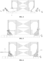
- FIG. 2 is a schematic structural view of a motor bearing according to the specific embodiment of the present application before the motor bearing is dismounted and replaced.
- FIG. 3 is a partially schematic structural view of FIG. 2 .
- the long ejector rods 11 are mounted by the multiple mounting holes reserved in the proximal-end end cover 5, the long ejector rods 11 are inserted and mounted in the mounting holes respectively, and the tail ends of all the long ejector rods 11 abut against the rotor pressing ring 4 sleeved on the middle surface of the rotating shaft 1, and the rotor pressing ring 4 presses against a left side surface and a right side surface of the rotor iron core 2. So far, the two axial ends of the rotating shaft 1 abut against other structural member, the freedom of axial movement of the rotating shaft 1 is limited, and the rotor is fixed axially.
- FIG. 4 is a schematic structural view of the motor bearing according to the specific embodiment of the present application when the motor bearing is dismounted and replaced.
- the current positioning bearing assembly can be dismounted at the distal end of the rotating shaft 1, and then a new positioning bearing assembly is remounted at the mounting position on the rotating shaft 1.
- the current non-positioning bearing assembly 6 is dismounted at the proximal end of the rotating shaft 1, and then a new non-positioning bearing assembly 6 is remounted at the mounting position on the rotating shaft 1.
- the positioning bearing assembly mainly includes a positioning bearing 7 and a positioning bearing seat 9, and the non-positioning bearing assembly 6 mainly includes a non-positioning bearing and a non-positioning bearing seat.
- FIG. 5 is a schematic structural view of the motor bearing according to the specific embodiment of the present application after the motor bearing is dismounted and replaced.
- FIG. 6 is a schematic structural view of the motor bearing according to the specific embodiment of the present application after the positioning bearing seat is mounted in place.
- the anti-over-positioning motor bearing disassembly-free dismounting and mounting method can fix the rotating shaft 1 axially by axially moving the rotating shaft 1 and by using the abutment between the inner sealing ring 8 of the rotating shaft 1 and the distal-end end cover 10 and the abutment between the externally-inserted long ejector rods 11 and the rotor pressing ring 4, which can realize the disassembly-free dismounting and replacement of the motor bearing, and improve the efficiency of the dismounting and replacement.
- the certain gap is generated between the positioning bearing seat 9 and the distal-end end cover 10 by the axial movement of the rotating shaft 1, and the gap can be used for the mounting allowance of the positioning bearing assembly, which avoids the over-positioning of the positioning bearing 7 during the dismounting and replacement, and improves the product quality.
- an output end of a driving component oppositely abuts against an end surface of one end of the rotating shaft 1, so that the output end of the driving component can conveniently push the rotating shaft to move axially.
- a hydraulic cylinder may be selected as the driving component.
- the output end of the driving component generally abuts against an end surface (the left end surface shown in the figure, that is, an end surface of the proximal end) of an end where the non-positioning bearing assembly 6 on the rotating shaft 1 is located, so that the rotating shaft 1 can move axially from the left end surface shown in the figure to the right end surface shown in the figure (that is, an end surface of the distal end).
- FIG. 7 is a schematic structural view of the motor bearing according to another specific embodiment of the present application when the motor bearing is dismounted and replaced.
- the output end of the driving component can push the rotating shaft 1 axially to move toward an end where the positioning bearing assembly 7 is located by the preset distance.
- the non-positioning bearing assembly 6 and the positioning bearing 7 are respectively arranged at two ends of the rotating shaft 1, the embodiment is described with the non-positioning bearing assembly 6 arranged at the illustrated left end (the proximal end) of the rotating shaft 1 and the positioning bearing 7 arranged at the illustrated right end (the distal end) of the rotating shaft 1 as an example.
- the driving component when the driving component outputs power, the driving component can push the rotating shaft 1 according to a preset feeding speed axially to move at a constant speed until the preset distance is reached.
- an outer bevel edge of the inner sealing ring 8 can abut against a tail end of an extending plate on the inner wall of the distal-end end cover 10 when the rotating shaft 1 is driven to move axially by the preset distance.
- FIG. 9 is a schematic structural view showing three abutment structures between the inner sealing ring 8 and the distal-end end cover 10 according to another specific embodiment of the present application.
- the outer bevel edge of the inner sealing ring 8 may be an inclined surface or an arc surface
- the tail end of the extending plate on the inner wall of the distal-end end cover 10 may also be an inclined surface or an arc surface.
- an axial mounting position of the distal-end end cover 10 on the rotor can be adjusted first before the dismounting and replacement, so that an axial gap between the outer bevel edge of the inner sealing ring 8 and the tail end of the extending plate of the distal-end end cover 10 is smaller than an axial gap between an outer surface of the inner sealing ring 8 and an inner wall of the positioning bearing 7. As shown in FIG. 3 , line A is shorter than line B.
- each long ejector rod 11 is threadedly connected with the corresponding mounting hole respectively, that is, the long ejector rods 11 can be gradually screwed and mounted in the corresponding mounting hole.
- FIG. 8 is a schematic structural view showing two abutment structures between a long ejector rod 11 and a rotor pressing ring 4 according to another specific embodiment of the present application.
- the tail end of the long ejector rod 11 may be a flat surface, a conical surface or an arc surface.
Landscapes
- Engineering & Computer Science (AREA)
- Power Engineering (AREA)
- Manufacturing & Machinery (AREA)
- Mechanical Engineering (AREA)
- Manufacture Of Motors, Generators (AREA)
Applications Claiming Priority (2)
| Application Number | Priority Date | Filing Date | Title |
|---|---|---|---|
| CN202010574519.6A CN111669020B (zh) | 2020-06-22 | 2020-06-22 | 一种防过定位电机轴承免解体拆装方法 |
| PCT/CN2020/126393 WO2021258603A1 (zh) | 2020-06-22 | 2020-11-04 | 一种防过定位电机轴承免解体拆装方法 |
Publications (2)
| Publication Number | Publication Date |
|---|---|
| EP4156477A1 true EP4156477A1 (de) | 2023-03-29 |
| EP4156477A4 EP4156477A4 (de) | 2024-07-03 |
Family
ID=72389114
Family Applications (1)
| Application Number | Title | Priority Date | Filing Date |
|---|---|---|---|
| EP20941584.3A Pending EP4156477A4 (de) | 2020-06-22 | 2020-11-04 | Demontage- und montageverfahren für ein motorlager ohne umpositionierung |
Country Status (3)
| Country | Link |
|---|---|
| EP (1) | EP4156477A4 (de) |
| CN (1) | CN111669020B (de) |
| WO (1) | WO2021258603A1 (de) |
Cited By (1)
| Publication number | Priority date | Publication date | Assignee | Title |
|---|---|---|---|---|
| EP4686053A1 (de) * | 2024-07-26 | 2026-01-28 | Zollern GmbH & Co. KG | Lagertausch bei einer elektrischen maschine, insbesondere einem elektromotor |
Families Citing this family (6)
| Publication number | Priority date | Publication date | Assignee | Title |
|---|---|---|---|---|
| CN111669020B (zh) * | 2020-06-22 | 2021-09-24 | 中车株洲电机有限公司 | 一种防过定位电机轴承免解体拆装方法 |
| CN113676012A (zh) * | 2021-08-23 | 2021-11-19 | 中车株洲电机有限公司 | 一种辅助电机轴承更换工具及电机轴承更换方法 |
| CN113691070B (zh) * | 2021-08-25 | 2022-07-05 | 中车株洲电机有限公司 | 一种电机结构及其轴承更换方法 |
| CN114337045A (zh) * | 2021-11-25 | 2022-04-12 | 中车永济电机有限公司 | 一种可实现轴承防护的电机 |
| CN114337132B (zh) * | 2022-01-13 | 2024-04-26 | 中车株洲电机有限公司 | 一种用于大型电机运输用轴承防护方法 |
| CN115347717A (zh) * | 2022-08-04 | 2022-11-15 | 东风电驱动系统有限公司 | 一种电机结构及电机轴承拆卸方法 |
Family Cites Families (11)
| Publication number | Priority date | Publication date | Assignee | Title |
|---|---|---|---|---|
| US6608422B2 (en) * | 1999-05-06 | 2003-08-19 | Prestolite Electric, Inc. | Alternator with an electric contact bearing assembly |
| JP4939894B2 (ja) * | 2006-10-13 | 2012-05-30 | 株式会社東芝 | 電動機 |
| JP5535014B2 (ja) * | 2010-09-09 | 2014-07-02 | 株式会社東芝 | 電動機 |
| JP5462829B2 (ja) * | 2011-03-30 | 2014-04-02 | 株式会社日立製作所 | 電動機の軸受部構造 |
| JP5694477B2 (ja) * | 2013-10-02 | 2015-04-01 | 株式会社東芝 | 電動機 |
| CN205453426U (zh) * | 2016-03-23 | 2016-08-10 | 中车永济电机有限公司 | 电机运输用轴承防护装置 |
| CN110695920B (zh) * | 2019-11-14 | 2021-07-06 | 中车株洲电机有限公司 | 一种牵引电机轴承的拆卸装置 |
| CN110829746B (zh) * | 2019-11-14 | 2020-12-25 | 中车株洲电机有限公司 | 一种牵引电机轴承的拆卸装置及应用于该装置的方法 |
| CN110829745B (zh) * | 2019-11-14 | 2021-09-21 | 中车株洲电机有限公司 | 一种免解体拆装电机轴承方法 |
| CN110784055A (zh) * | 2019-11-14 | 2020-02-11 | 中车株洲电机有限公司 | 一种牵引电机及其转子轴承免解体拆装结构 |
| CN111669020B (zh) * | 2020-06-22 | 2021-09-24 | 中车株洲电机有限公司 | 一种防过定位电机轴承免解体拆装方法 |
-
2020
- 2020-06-22 CN CN202010574519.6A patent/CN111669020B/zh active Active
- 2020-11-04 EP EP20941584.3A patent/EP4156477A4/de active Pending
- 2020-11-04 WO PCT/CN2020/126393 patent/WO2021258603A1/zh not_active Ceased
Cited By (1)
| Publication number | Priority date | Publication date | Assignee | Title |
|---|---|---|---|---|
| EP4686053A1 (de) * | 2024-07-26 | 2026-01-28 | Zollern GmbH & Co. KG | Lagertausch bei einer elektrischen maschine, insbesondere einem elektromotor |
Also Published As
| Publication number | Publication date |
|---|---|
| CN111669020A (zh) | 2020-09-15 |
| WO2021258603A1 (zh) | 2021-12-30 |
| EP4156477A4 (de) | 2024-07-03 |
| CN111669020B (zh) | 2021-09-24 |
Similar Documents
| Publication | Publication Date | Title |
|---|---|---|
| CN111669020A (zh) | 一种防过定位电机轴承免解体拆装方法 | |
| WO2021258602A1 (zh) | 一种防过定位电机轴承免解体拆装方法 | |
| CN206922525U (zh) | 转子构件、转子以及电动机 | |
| CN108723699B (zh) | 一种定子铁芯与机壳的热套定位工装 | |
| EP1895641B1 (de) | Lagerloser Direktantrieb | |
| EP3975395A1 (de) | Demontagefreie motorlagerdemontage und montageverfahren | |
| US20220271607A1 (en) | Electric motor | |
| EP3361610A1 (de) | Stator für einen linearschrittmotor und verfahren zu dessen herstellung | |
| US7658365B2 (en) | Assemblies and methods for coupling a component to an actuator | |
| CN116652022B (zh) | 一种排气扩压器旋压夹具的工作方法 | |
| CN108080925B (zh) | 一种环形腔内滚子轴承外圈分解装置及方法 | |
| CN112622116A (zh) | 一种用于模具型腔曲面快速构造的柔性基体装置 | |
| EP4427631A1 (de) | Schiebestruktur, montageverfahren und aktuator | |
| CN218693723U (zh) | 一种压铸机可调节抽哥机构 | |
| CN118842248A (zh) | 一种永磁伺服电机定转子合装与分离装置 | |
| CN218454886U (zh) | 版辊轴承自动拆装设备 | |
| CN216290602U (zh) | 一种伺服电机定子精车双锥度治具 | |
| CN211959027U (zh) | 具有防抖功能的电机机壳端部辊压成型装置及电机 | |
| CN111669019A (zh) | 一种防过定位电机轴承免解体拆装方法 | |
| CN222570452U (zh) | 一种具有压紧固定功能的固定组件 | |
| CN115589095B (zh) | 一种电动机转动轴安装结构及其安装方法 | |
| KR20030030828A (ko) | 리니어 액츄에이터 | |
| CN117282824B (zh) | 一种用于制备定子屏蔽套上膨胀节的工装 | |
| CN121670608A (zh) | 执行器 | |
| CN218582210U (zh) | 一种变速器合箱装置 |
Legal Events
| Date | Code | Title | Description |
|---|---|---|---|
| STAA | Information on the status of an ep patent application or granted ep patent |
Free format text: STATUS: THE INTERNATIONAL PUBLICATION HAS BEEN MADE |
|
| PUAI | Public reference made under article 153(3) epc to a published international application that has entered the european phase |
Free format text: ORIGINAL CODE: 0009012 |
|
| STAA | Information on the status of an ep patent application or granted ep patent |
Free format text: STATUS: REQUEST FOR EXAMINATION WAS MADE |
|
| 17P | Request for examination filed |
Effective date: 20221219 |
|
| AK | Designated contracting states |
Kind code of ref document: A1 Designated state(s): AL AT BE BG CH CY CZ DE DK EE ES FI FR GB GR HR HU IE IS IT LI LT LU LV MC MK MT NL NO PL PT RO RS SE SI SK SM TR |
|
| DAV | Request for validation of the european patent (deleted) | ||
| DAX | Request for extension of the european patent (deleted) | ||
| REG | Reference to a national code |
Ref country code: DE Ref legal event code: R079 Free format text: PREVIOUS MAIN CLASS: H02K0015140000 Ipc: H02K0015000000 |
|
| A4 | Supplementary search report drawn up and despatched |
Effective date: 20240603 |
|
| RIC1 | Information provided on ipc code assigned before grant |
Ipc: H02K 5/173 20060101ALI20240527BHEP Ipc: H02K 15/00 20060101AFI20240527BHEP |