EP4156476B1 - Antriebseinheit für ein serielles hybridfahrzeug - Google Patents
Antriebseinheit für ein serielles hybridfahrzeug Download PDFInfo
- Publication number
- EP4156476B1 EP4156476B1 EP20936710.1A EP20936710A EP4156476B1 EP 4156476 B1 EP4156476 B1 EP 4156476B1 EP 20936710 A EP20936710 A EP 20936710A EP 4156476 B1 EP4156476 B1 EP 4156476B1
- Authority
- EP
- European Patent Office
- Prior art keywords
- cooling passage
- passage
- inner housing
- electric motor
- helical
- Prior art date
- Legal status (The legal status is an assumption and is not a legal conclusion. Google has not performed a legal analysis and makes no representation as to the accuracy of the status listed.)
- Active
Links
Images







Classifications
-
- H—ELECTRICITY
- H02—GENERATION; CONVERSION OR DISTRIBUTION OF ELECTRIC POWER
- H02K—DYNAMO-ELECTRIC MACHINES
- H02K5/00—Casings; Enclosures; Supports
- H02K5/04—Casings or enclosures characterised by the shape, form or construction thereof
- H02K5/20—Casings or enclosures characterised by the shape, form or construction thereof with channels or ducts for flow of cooling medium
- H02K5/203—Casings or enclosures characterised by the shape, form or construction thereof with channels or ducts for flow of cooling medium specially adapted for liquids, e.g. cooling jackets
-
- B—PERFORMING OPERATIONS; TRANSPORTING
- B60—VEHICLES IN GENERAL
- B60K—ARRANGEMENT OR MOUNTING OF PROPULSION UNITS OR OF TRANSMISSIONS IN VEHICLES; ARRANGEMENT OR MOUNTING OF PLURAL DIVERSE PRIME-MOVERS IN VEHICLES; AUXILIARY DRIVES FOR VEHICLES; INSTRUMENTATION OR DASHBOARDS FOR VEHICLES; ARRANGEMENTS IN CONNECTION WITH COOLING, AIR INTAKE, GAS EXHAUST OR FUEL SUPPLY OF PROPULSION UNITS IN VEHICLES
- B60K1/00—Arrangement or mounting of electrical propulsion units
-
- B—PERFORMING OPERATIONS; TRANSPORTING
- B60—VEHICLES IN GENERAL
- B60K—ARRANGEMENT OR MOUNTING OF PROPULSION UNITS OR OF TRANSMISSIONS IN VEHICLES; ARRANGEMENT OR MOUNTING OF PLURAL DIVERSE PRIME-MOVERS IN VEHICLES; AUXILIARY DRIVES FOR VEHICLES; INSTRUMENTATION OR DASHBOARDS FOR VEHICLES; ARRANGEMENTS IN CONNECTION WITH COOLING, AIR INTAKE, GAS EXHAUST OR FUEL SUPPLY OF PROPULSION UNITS IN VEHICLES
- B60K6/00—Arrangement or mounting of plural diverse prime-movers for mutual or common propulsion, e.g. hybrid propulsion systems comprising electric motors and internal combustion engines
- B60K6/20—Arrangement or mounting of plural diverse prime-movers for mutual or common propulsion, e.g. hybrid propulsion systems comprising electric motors and internal combustion engines the prime-movers consisting of electric motors and internal combustion engines, e.g. HEVs
- B60K6/22—Arrangement or mounting of plural diverse prime-movers for mutual or common propulsion, e.g. hybrid propulsion systems comprising electric motors and internal combustion engines the prime-movers consisting of electric motors and internal combustion engines, e.g. HEVs characterised by apparatus, components or means specially adapted for HEVs
- B60K6/26—Arrangement or mounting of plural diverse prime-movers for mutual or common propulsion, e.g. hybrid propulsion systems comprising electric motors and internal combustion engines the prime-movers consisting of electric motors and internal combustion engines, e.g. HEVs characterised by apparatus, components or means specially adapted for HEVs characterised by the motors or the generators
-
- B—PERFORMING OPERATIONS; TRANSPORTING
- B60—VEHICLES IN GENERAL
- B60K—ARRANGEMENT OR MOUNTING OF PROPULSION UNITS OR OF TRANSMISSIONS IN VEHICLES; ARRANGEMENT OR MOUNTING OF PLURAL DIVERSE PRIME-MOVERS IN VEHICLES; AUXILIARY DRIVES FOR VEHICLES; INSTRUMENTATION OR DASHBOARDS FOR VEHICLES; ARRANGEMENTS IN CONNECTION WITH COOLING, AIR INTAKE, GAS EXHAUST OR FUEL SUPPLY OF PROPULSION UNITS IN VEHICLES
- B60K6/00—Arrangement or mounting of plural diverse prime-movers for mutual or common propulsion, e.g. hybrid propulsion systems comprising electric motors and internal combustion engines
- B60K6/20—Arrangement or mounting of plural diverse prime-movers for mutual or common propulsion, e.g. hybrid propulsion systems comprising electric motors and internal combustion engines the prime-movers consisting of electric motors and internal combustion engines, e.g. HEVs
- B60K6/42—Arrangement or mounting of plural diverse prime-movers for mutual or common propulsion, e.g. hybrid propulsion systems comprising electric motors and internal combustion engines the prime-movers consisting of electric motors and internal combustion engines, e.g. HEVs characterised by the architecture of the hybrid electric vehicle
- B60K6/46—Series type
-
- B—PERFORMING OPERATIONS; TRANSPORTING
- B60—VEHICLES IN GENERAL
- B60L—PROPULSION OF ELECTRICALLY-PROPELLED VEHICLES; SUPPLYING ELECTRIC POWER FOR AUXILIARY EQUIPMENT OF ELECTRICALLY-PROPELLED VEHICLES; ELECTRODYNAMIC BRAKE SYSTEMS FOR VEHICLES IN GENERAL; MAGNETIC SUSPENSION OR LEVITATION FOR VEHICLES; MONITORING OPERATING VARIABLES OF ELECTRICALLY-PROPELLED VEHICLES; ELECTRIC SAFETY DEVICES FOR ELECTRICALLY-PROPELLED VEHICLES
- B60L50/00—Electric propulsion with power supplied within the vehicle
- B60L50/10—Electric propulsion with power supplied within the vehicle using propulsion power supplied by engine-driven generators, e.g. generators driven by combustion engines
- B60L50/16—Electric propulsion with power supplied within the vehicle using propulsion power supplied by engine-driven generators, e.g. generators driven by combustion engines with provision for separate direct mechanical propulsion
-
- H—ELECTRICITY
- H02—GENERATION; CONVERSION OR DISTRIBUTION OF ELECTRIC POWER
- H02K—DYNAMO-ELECTRIC MACHINES
- H02K11/00—Structural association of dynamo-electric machines with electric components or with devices for shielding, monitoring or protection
- H02K11/30—Structural association with control circuits or drive circuits
- H02K11/33—Drive circuits, e.g. power electronics
-
- H—ELECTRICITY
- H02—GENERATION; CONVERSION OR DISTRIBUTION OF ELECTRIC POWER
- H02K—DYNAMO-ELECTRIC MACHINES
- H02K7/00—Arrangements for handling mechanical energy structurally associated with dynamo-electric machines, e.g. structural association with mechanical driving motors or auxiliary dynamo-electric machines
- H02K7/006—Structural association of a motor or generator with the drive train of a motor vehicle
-
- H—ELECTRICITY
- H02—GENERATION; CONVERSION OR DISTRIBUTION OF ELECTRIC POWER
- H02K—DYNAMO-ELECTRIC MACHINES
- H02K9/00—Arrangements for cooling or ventilating
- H02K9/19—Arrangements for cooling or ventilating for machines with closed casing and closed-circuit cooling using a liquid cooling medium, e.g. oil
-
- H—ELECTRICITY
- H02—GENERATION; CONVERSION OR DISTRIBUTION OF ELECTRIC POWER
- H02K—DYNAMO-ELECTRIC MACHINES
- H02K9/00—Arrangements for cooling or ventilating
- H02K9/22—Arrangements for cooling or ventilating by solid heat conducting material embedded in, or arranged in contact with, the stator or rotor, e.g. heat bridges
-
- B—PERFORMING OPERATIONS; TRANSPORTING
- B60—VEHICLES IN GENERAL
- B60K—ARRANGEMENT OR MOUNTING OF PROPULSION UNITS OR OF TRANSMISSIONS IN VEHICLES; ARRANGEMENT OR MOUNTING OF PLURAL DIVERSE PRIME-MOVERS IN VEHICLES; AUXILIARY DRIVES FOR VEHICLES; INSTRUMENTATION OR DASHBOARDS FOR VEHICLES; ARRANGEMENTS IN CONNECTION WITH COOLING, AIR INTAKE, GAS EXHAUST OR FUEL SUPPLY OF PROPULSION UNITS IN VEHICLES
- B60K11/00—Arrangement in connection with cooling of propulsion units
- B60K11/02—Arrangement in connection with cooling of propulsion units with liquid cooling
-
- B—PERFORMING OPERATIONS; TRANSPORTING
- B60—VEHICLES IN GENERAL
- B60K—ARRANGEMENT OR MOUNTING OF PROPULSION UNITS OR OF TRANSMISSIONS IN VEHICLES; ARRANGEMENT OR MOUNTING OF PLURAL DIVERSE PRIME-MOVERS IN VEHICLES; AUXILIARY DRIVES FOR VEHICLES; INSTRUMENTATION OR DASHBOARDS FOR VEHICLES; ARRANGEMENTS IN CONNECTION WITH COOLING, AIR INTAKE, GAS EXHAUST OR FUEL SUPPLY OF PROPULSION UNITS IN VEHICLES
- B60K1/00—Arrangement or mounting of electrical propulsion units
- B60K2001/003—Arrangement or mounting of electrical propulsion units with means for cooling the electrical propulsion units
-
- B—PERFORMING OPERATIONS; TRANSPORTING
- B60—VEHICLES IN GENERAL
- B60K—ARRANGEMENT OR MOUNTING OF PROPULSION UNITS OR OF TRANSMISSIONS IN VEHICLES; ARRANGEMENT OR MOUNTING OF PLURAL DIVERSE PRIME-MOVERS IN VEHICLES; AUXILIARY DRIVES FOR VEHICLES; INSTRUMENTATION OR DASHBOARDS FOR VEHICLES; ARRANGEMENTS IN CONNECTION WITH COOLING, AIR INTAKE, GAS EXHAUST OR FUEL SUPPLY OF PROPULSION UNITS IN VEHICLES
- B60K1/00—Arrangement or mounting of electrical propulsion units
- B60K2001/003—Arrangement or mounting of electrical propulsion units with means for cooling the electrical propulsion units
- B60K2001/006—Arrangement or mounting of electrical propulsion units with means for cooling the electrical propulsion units the electric motors
-
- B—PERFORMING OPERATIONS; TRANSPORTING
- B60—VEHICLES IN GENERAL
- B60Y—INDEXING SCHEME RELATING TO ASPECTS CROSS-CUTTING VEHICLE TECHNOLOGY
- B60Y2200/00—Type of vehicle
- B60Y2200/90—Vehicles comprising electric prime movers
- B60Y2200/92—Hybrid vehicles
-
- B—PERFORMING OPERATIONS; TRANSPORTING
- B60—VEHICLES IN GENERAL
- B60Y—INDEXING SCHEME RELATING TO ASPECTS CROSS-CUTTING VEHICLE TECHNOLOGY
- B60Y2306/00—Other features of vehicle sub-units
- B60Y2306/05—Cooling
-
- B—PERFORMING OPERATIONS; TRANSPORTING
- B60—VEHICLES IN GENERAL
- B60Y—INDEXING SCHEME RELATING TO ASPECTS CROSS-CUTTING VEHICLE TECHNOLOGY
- B60Y2400/00—Special features of vehicle units
- B60Y2400/60—Electric Machines, e.g. motors or generators
-
- B—PERFORMING OPERATIONS; TRANSPORTING
- B60—VEHICLES IN GENERAL
- B60Y—INDEXING SCHEME RELATING TO ASPECTS CROSS-CUTTING VEHICLE TECHNOLOGY
- B60Y2400/00—Special features of vehicle units
- B60Y2400/61—Arrangements of controllers for electric machines, e.g. inverters
-
- Y—GENERAL TAGGING OF NEW TECHNOLOGICAL DEVELOPMENTS; GENERAL TAGGING OF CROSS-SECTIONAL TECHNOLOGIES SPANNING OVER SEVERAL SECTIONS OF THE IPC; TECHNICAL SUBJECTS COVERED BY FORMER USPC CROSS-REFERENCE ART COLLECTIONS [XRACs] AND DIGESTS
- Y02—TECHNOLOGIES OR APPLICATIONS FOR MITIGATION OR ADAPTATION AGAINST CLIMATE CHANGE
- Y02T—CLIMATE CHANGE MITIGATION TECHNOLOGIES RELATED TO TRANSPORTATION
- Y02T10/00—Road transport of goods or passengers
- Y02T10/60—Other road transportation technologies with climate change mitigation effect
- Y02T10/62—Hybrid vehicles
-
- Y—GENERAL TAGGING OF NEW TECHNOLOGICAL DEVELOPMENTS; GENERAL TAGGING OF CROSS-SECTIONAL TECHNOLOGIES SPANNING OVER SEVERAL SECTIONS OF THE IPC; TECHNICAL SUBJECTS COVERED BY FORMER USPC CROSS-REFERENCE ART COLLECTIONS [XRACs] AND DIGESTS
- Y02—TECHNOLOGIES OR APPLICATIONS FOR MITIGATION OR ADAPTATION AGAINST CLIMATE CHANGE
- Y02T—CLIMATE CHANGE MITIGATION TECHNOLOGIES RELATED TO TRANSPORTATION
- Y02T10/00—Road transport of goods or passengers
- Y02T10/60—Other road transportation technologies with climate change mitigation effect
- Y02T10/64—Electric machine technologies in electromobility
Definitions
- the present invention relates to a drive unit for a series hybrid vehicle.
- WO2015/098328A1 discloses an electric motor of cooler-liquid-cooled type in which a helical cooling passage is formed inside a housing in which a stator is fixed, and a coolant inlet provided at one end of the cooling passage and a coolant outlet provided at the other end open to the outer periphery of the housing.
- JP 2003 087908 A discloses the features as defined in the preamble part of the appended claim 1.
- the two electric motors are arranged in close proximity with the rotational axes parallel to each other in order to make a drive unit including the two electric motors more compact. If a cooling passage, which has the coolant inlet and the coolant outlet as in the above-described document, is applied to the two electric motors of a series hybrid vehicle, the cooling passage of one and the cooling passage of the other would be connected in series. That is, the coolant outlet of one electric motor is connected to the coolant inlet of the other electric motor.
- the coolant outlet of the one electric motor and the coolant inlet of the other electric motor are separated in the axial direction, resulting in a longer connecting passage to connect them and, hence, a larger drive unit.
- the longer cooling liquid passage also results in greater pressure loss.
- an object of the present invention is to provide a drive unit that is compact and also able to suppress pressure loss in the cooling passage.
- FIG. 1 is an external view of a drive unit 100 according to an embodiment.
- the drive unit 100 is used to drive a series hybrid vehicle and includes a drive motor 15, a generator motor 17, an inverter 13, a speed reduction mechanism 18, and a speed increase mechanism 19, which will be described further below.
- the drive motor 15 and the generator motor 17 are cooler-liquid-cooled types, and the drive unit 100 is equipped with a cooling system of cooler-liquid-cooled type.
- the cooling system consists of a radiator 1, a water pump 2, external cooling passages 3-6, and internal cooling passages.
- the internal cooling passages consist of an inverter cooling passage 42 formed integrally with the inverter 13, a drive motor cooling passage (not shown) that cools the drive motor 15, and a generator motor cooling passage (not shown) that cools the generator motor 17, which are interconnected in the housing of the drive unit 100. These internal cooling passages will be described in detail below.
- Coolant cooled by the radiator 1 flows into the inverter cooling passage 42 via the first external cooling passage 3, the water pump 2, and the second external cooling passage 4, passes through the drive motor cooling passage and the generator motor cooling passage, and returns to the radiator 1 via the third external cooling passage 6.
- the inverter 13, the drive motor 15, and the generator motor 17 are cooled using the internal cooling passages, so that the external cooling passages only require two paths, the path from the radiator 1 to the drive unit 100 (first external cooling passage 3 and second external cooling passage 4), and the path from the drive unit 100 to the radiator 1 (the third external cooling passage 6).
- FIG 2 shows a drive unit 101 as a comparative example.
- the drive unit 101 of the comparative example is the same as the drive unit 100 in that the inverter 13, the drive motor 15, and the generator motor 17 are integrated, but the cooling passages for cooling these elements are connected via external cooling passages. That is, in addition to the first external cooling passage 3, the second external cooling passage 4, and the third external cooling passage 6 of Figure 1 , an external cooling passage 7 that connects a cooling passage for the inverter and a cooling passage for the drive motor, as well as an external cooling passage 8 that connects the cooling passage for the drive motor and a cooling passage for the generator motor are required.
- the drive unit 100 and the cooling system of this embodiment have fewer external cooling passages than the drive unit 101 and the cooling system of the comparative example. That is, the drive unit 100 and the cooling system of this embodiment have a more compact configuration than the configuration of the comparative example and have greater flexibility of design of the layout when mounted in a vehicle.
- Figure 3 is an exploded view of the drive unit 100 according to this embodiment.
- the housing of the drive unit 100 comprises an outer housing 10, a gear cover 11 that is attached to one end portion of the outer housing 10, and a rear cover 12 that is attached to the other end portion of the outer housing 10.
- the outer housing 10 has the form of two parallel cylindrical sections.
- the drive motor 15 and a first inner housing 14 in which the drive motor is accommodated are housed in one cylindrical portion, and the generator motor 17 and a second inner housing 16 in which the generator motor is accommodated are housed in the other cylindrical portion.
- the drive motor 15 consists of a stator 15B that is fixed inside the inner housing 14 and a rotor 15A that is fixed to the rear cover 12.
- the generator motor 17 also consists of a stator 17B that is fixed inside the inner housing 16 and a rotor 17A that is fixed to the rear cover 12.
- the inverter 13 is mounted on the upper portion of the outer housing 10.
- the upper portion here is the part above the plane that includes the axis of rotation of the drive motor 15 and the axis of rotation of the generator motor 17.
- the drive unit 100 may be mounted in the vehicle in a state in which the plane that includes the axes of rotation of the two motors 15, 17 is inclined with respect to the horizontal direction, as shown in Figure 4 , in this embodiment, the part above the plane in the perpendicular direction is referred to as the upper side, and the part below the plane is referred to as the lower side.
- the gear cover 11 houses the speed reduction mechanism 18 connected to the drive motor 15, the speed increase mechanism 19 connected to the generator motor 17, and a mechanical pump 20.
- a sensor 21 that detects the rotational speed of the drive motor 15, a sensor 22 that detects the rotational speed of the generator motor 17, and a sensor cover 23 that covers these sensors are attached to the rear cover 12.
- a shielding plate 24, described further below, is attached to the outer housing 10.
- the inner housings 14, 16 will now be described.
- the first inner housing 14 and the second inner housing 16 have the same structure and are thus referred to as inner housing IHSG when there is no need to distinguish between them.
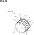
- Figure 5 is an external view of the inner housing IHSG.
- the stators of the motors 15, 17 are fixed to inner circumference 30 of the inner housing IHSG.
- a helical groove 32 is formed from one end to the other of outer circumferential surface 31 of the inner housing IHSG.
- the helical cooling passage 32 When the inner housing IHSG is housed in the outer housing 10, the upper opening of the groove 32 is closed by the inner circumferential surface of the outer housing 10, thereby forming a helical cooling passage (hereinafter referred to as the helical cooling passage 32).
- the upper openings at both ends of the helical cooling passage 32 are not closed, even when housed in the outer housing 10, and function as an inlet for introducing coolant into, or an outlet for discharging coolant from, the helical cooling passage 32.
- the end portion on the opposite side of a flange 33 of the helical cooling passage 32 is referred to as a first opening 35, and the end portion on the flange side is referred to as a second opening 36.
- the reason for providing the helical cooling passage 32 from one end of the inner housing IHSG to the other is to cover the cooling passage 32 from one axial end to the other of the outer periphery of each of the motors 15, 17 in contact with the inner circumference 30 of the inner housing IHSG, in order to further enhance the cooling effect.
- the helical cooling passage 32 is formed such that the first opening 35 and the second opening 36 are positioned to form a prescribed angle with respect to the central axis when seen from the direction of the rotor axis, as shown in Figure 7 , described further below.
- the helical cooling passage 32 is provided from one end of the inner housing IHSG to the other from the standpoint of the cooling effect, so that if the position of the first opening 35 is set, the position of the second opening 36 will also be set. That is, it is not possible to set the position of the first opening 35 independently of the position of the second opening 36.
- one end of the inner housing IHSG has a flange 33 with a plurality of fastening parts 34 for securing the inner housing to the rear cover 12 using bolts or the like.
- the rear cover 12 is fixed to the outer housing 10, resulting in the inner housing IHSG being fixed to the outer housing 10 via the rear cover 12.
- the inner housing IHSG may be directly fixed to the outer housing 10.
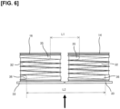
- Figure 6 is a top view of the first inner housing 14 and the second inner housing 16 in the housed state.
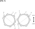
- Figure 7 is a view of the first inner housing 14 and the second inner housing 16 of Figure 6 as seen from the flange 33 side.
- phase means the mounting angle with respect to the outer housing 10. That is, for example, as shown in Figure 7 , the straight line connecting the first opening 35 and the second opening 36 of the first inner housing 14 and the straight line connecting the first opening 35 and the second opening 36 of the second inner housing 16 are at different angles to the vertical direction of the outer housing 10 (the direction of the arrow in the figure).
- the inner housings IHSG are housed in the outer housing 10 with a phase in which the first openings 35 of the adjacent inner housings IHSG are close to each other, and the second openings 36 of the adjacent inner housings IHSG are far from each other. This makes the distance L1 from the first opening 35 of the first inner housing 14 to the first opening 35 of the second inner housing 16 shorter than the distance L2 from the second opening 36 of the first inner housing 14 to the second opening 36 of the second inner housing 16.
- Figure 8 is a schematic diagram of the drive unit 100 as seen from the same direction as in Figure 7 .
- the inverter 13 has a first power module 40 and a second power module 41 that constitute an inverter circuit and the inverter cooling passage 42 that cools the power modules.
- the inverter cooling passage 42 is configured such that coolant introduced from the water pump 2 cools the first power module 40 and then cools the second power module 41.
- a liquid seal 47 for ensuring airtightness is interposed between the inverter 13 and the outer housing 10.
- An O-ring 48 for ensuring watertightness which will be described further below, is disposed at a connecting portion between the inverter cooling passage 42 and an outer housing introduction passage 43, also described further below.
- the inverter cooling passage 42 after passing through the second power module 41 is connected to the outer housing introduction passage 43 provided in the outer housing 10.
- the outer housing introduction passage 43 is connected to the second opening 36 of the first inner housing 14. That is, the second opening 36 of the first inner housing 14 functions as a coolant inlet. On the other hand, the first opening 35 of the first inner housing 14 functions as a coolant outlet.
- the first opening 35 of the first inner housing 14A is connected to the first vertical passage 45A of a connecting channel 45, which includes the first vertical passage 45A, a horizontal passage 45B, a second vertical passage 45C, and a cover 46.
- the connecting passage 45 will be described further below.
- the second vertical passage 45C of the connecting passage 45 is connected to the first opening 35 of the second inner housing 16. That is, the first opening 35 of the second inner housing 16 functions as a coolant inlet. On the other hand, the second opening 36 of the second inner housing 16 functions as a coolant outlet. An outer housing discharge passage 44 is connected to the second opening 36 of the second inner housing 16.
- a connecting portion 49 between the inverter cooling passage 42 and the outer housing introduction passage 43 will now be described with reference to Figures 9 and 10 .
- Figure 9 is an enlarged view in the vicinity of the connecting portion 49 of the outer housing 10.
- Figure 10 shows a cross section of the connecting portion 49.
- An inverter circuit placement area 52 is surrounded by a liquid seal placement surface 51.
- the outer housing introduction passage 43 is located on the outside of the inverter circuit placement area 52.
- a trap groove 50 is provided between the liquid seal placement surface 51 and the connecting portion 49. As shown in Figure 10 , a groove may be formed in the inverter at a location opposite the trap groove 50.
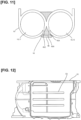
- Figure 11 schematically shows a cross section of the outer housing 10, in which is housed the first inner housing 14, the drive motor 15, the second inner housing 16, and the generator motor 17, as seen from the direction of the rotor axis of the motors 15, 17.
- Figure 12 shows the outer housing 10 as seen from below.
- the outer housing 10 has the form of connected cylinders that house the drive motor 15 and the generator motor 17.
- a plurality of ribs 53 are formed in the valley sandwiched between the two cylindrical portions at prescribed intervals in the axial direction, as shown in Figure 12 .
- the ribs 53 may be provided not only on the lower surface of the outer housing 10, but also on the upper surface.
- One of the plurality of ribs 53 is provided such that the position thereof in the direction of the rotor axis is aligned with the first opening 35 of the first inner housing 14 and the first opening 35 of the second inner housing 16.
- the connecting passage 45 is formed on this rib 53.
- the first vertical passage 45A penetrates from a lower end surface of the rib 53 to the interior of the outer housing 10.
- the end portion of the first vertical passage 45A on the inner side of the outer housing 10 opens opposite to the first opening 35 of the first inner housing 14.
- the second vertical passage 45C penetrates from the lower end surface of the rib 53 to the interior of the outer housing 10.
- the end portion of the second vertical passage 45C on the inner side of the outer housing 10 opens opposite to the first opening 35 of the second inner housing 16.
- the horizontal passage 45B is a groove provided in the lower end surface of the rib 53, connecting the opening of the first vertical passage 45A and the opening of the second vertical passage 45C. When this groove is closed by the cover 46 from below, the first vertical passage 45A, the horizontal passage 45B, and the second vertical passage 45C form the connecting passage 45 that connects the first opening 35 of the first inner housing 14 and the first opening 35 of the second inner housing 16.
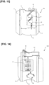
- Figure 13 is a top view of the drive unit 100.
- Figure 14 is a view of the drive unit 100 from the side on which the drive motor 15 is housed, that is, the drive unit 100 is viewed from above the plane of the paper of Figure 13 .
- Figure 15 is an enlarged view in the vicinity of the connecting passage 45 as seen from the rear cover 12 side.
- Figure 16 is a view of the drive unit 100 as seen from the generator motor 17 side.
- the coolant cooled by the radiator 1 flows into the inverter cooling passage 42, as shown in Figure 13 .
- the coolant that has cooled the drive motor 15 flows into the helical cooling passage 32 of the second inner housing 16 via the connecting passage 45, as shown in Figure 15 , and cools the generator motor 17, as shown in Figure 16 .
- the coolant cools the inverter 13, the drive motor 15, and the generator motor 17, in that order. That is, in this embodiment, when viewed in the order of the coolant flow, the drive motor 15 is the upstream side motor and the generator motor 17 is the downstream side motor.
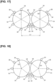
- phase setting method will be described with reference to Figures 17 to 20 .
- Figure 17 shows the case of an equally spaced arrangement of six fastening parts 34 in the circumferential direction, in the same manner as shown in Figure 8 , etc.
- the distance L3 between the axes of the first inner housing 14 and the second inner housing 16 must be reduced.
- the outer peripheries of the first inner housing 14 and the second inner housing 16 must be brought close together.
- two of the fastening parts 34 on the second inner housing 16 side, from among the six fastening parts 34 of the second inner housing 16, and two of the fastening parts 34 on the first inner housing 14 side, from among the six fastening parts 34 of the first inner housing 14, must be respectively in phases opposite each other.
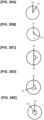
- the phase difference patterns that satisfy this condition are shown in Figures 19A to 19F .
- Figure 19A to 19F are diagrams in which the first inner housing 14 and the second inner housing 16 are concentrically superposed, and the phase difference is represented by reference lines D1, D2 that connect the centers and the respective reference fastening parts 34.
- Figure 19A shows the state of Figure 17 , that is, the case in which the phase difference ⁇ is zero.
- the phase difference ⁇ is a multiple of the value obtained by dividing 360 degrees by the number of fastening parts 34 (six), i.e., a multiple of 60 degrees.
- the arrangement of the fastening parts 34 will be the same as that shown in Figure 17 for any phase difference ⁇ .
- the outer peripheries of the first inner housing 14 and the second inner housing 16 must still be brought close together in order to make the drive unit 100 have a compact configuration, in the same manner as when there are an even number of the fastening parts 34.
- the arrangement would be as shown in Figure 18 .
- there is a phase difference between the first inner housing 14 and the second inner housing 16. That is, the reference line D3 of the first inner housing 14 and the reference line D4 of the second inner housing 16 are not parallel, and the phase difference ⁇ is 360 degrees ⁇ 5 ⁇ 2 36 degrees.
- phase differences ⁇ when the number of the fastening parts 34 is five are as shown in Figures 20A to 20E.
- Figures 20A to 20E show the phase differences ⁇ , in the same manner as in Figures 19A to 19F
- Figure 20A shows the state of Figure 18 .
- phase difference ⁇ out of the possible phase differences ⁇ described above will be adopted in accordance with the drive unit 100 to be used.
- the drive unit 100 is a drive unit of a series hybrid vehicle and comprises the drive motor 15 (first electric motor for driving) and the generator motor 17 (second electric motor).
- the first cylindrical inner housing 14 provided on the outer periphery of the stator of the drive motor 15 and the second cylindrical inner housing 16 provided on the outer periphery of the stator of the generator motor are each provided with the helical cooling passage 32 on the respective outer periphery, formed so as to surround each stator in helical fashion.
- the drive motor 15 and the generator motor 17 are housed in the outer housing 10 such that the rotor axes are parallel.
- the helical cooling passage 32 of the drive motor 15 and the helical cooling passage 32 of the generator motor 17 are connected in series via the connecting passage 45, and the first opening 35 (coolant outlet) of the helical cooling passage 32 on the upstream side to which one end of the connecting passage 45 is connected and the first opening 35 (coolant inlet) of the helical cooling passage 32 on the downstream side to which the other end of the connecting passage 45 is connected are arranged at the end portions on the same side in the direction of the rotor axis.
- the first opening 35 becomes the coolant outlet
- the first opening 35 becomes the coolant inlet.
- the length of the channel of the connecting passage 45 can be suppressed, compared with the case in which the first opening 35 is set as the coolant outlet and the second opening 36 is set as the coolant inlet.
- the drive unit 100 can be made compact.
- the first inner housing 14 and the second inner housing 16 are housed in the outer housing 10 so that the respective helical cooling passages 32 have different phases.
- the same parts can be used for the inner housing 14 that houses the drive motor 15 and the inner housing 16 that houses the generator motor 17.
- the parts count is reduced compared with the case in which two types of inner housings IHSGs are used, so that the manufacturing cost of the drive unit 100 can be suppressed.
- the diameter of the drive motor 15 and the diameter of the generator motor 17 are the same was described in the above embodiment, no limitation is imposed thereby; for example, if the motors to be used are changed and the diameter of the drive motor 15 and the diameter of the generator motor 17 are different, two types of inner housings IHSG could be used. However, even in this case, if the pitch of the helix of the helical cooling passage 32 on the upstream side matches the pitch of the helix of the helical cooling passage 32 on the downstream side, the flow path need not be redesigned.
- the pitch of the helix is the distance between the valleys of the inner housing IHSG in the axial direction.
- the distance between the first opening 35 (coolant outlet) of the helical cooling passage 32 on the upstream side and the first opening 35 (coolant inlet) of the helical cooling passage 32 on the downstream side is shorter than the distance between the second opening 36 (coolant outlet) of the helical cooling passage 32 on the downstream side and the second opening 36 (coolant inlet) of the helical cooling passage 32 on the upstream side.
- the length of the channel of the connecting passage 45 can be further suppressed.
- the inverter 13 is disposed on the upper portion of the outer housing 10, the first opening 35 (coolant outlet) of the helical cooling passage 32 on the upstream side is disposed below the rotor axis of the drive motor 15 (the electric motor on the upstream side), and the first opening 35 (coolant inlet) of the helical cooling passage 32 on the downstream side is disposed below the rotor axis of the generator motor 17 (the electric motor on the downstream side). That is, the inverter 13 is disposed in a position higher than the connecting portion between the connecting passage 45 and the two helical cooling passages 32. Thus, even in the event of a leak due to a problem in the connecting portion, leakage into the inverter circuit can be prevented.
- the inverter 13 is disposed on the upper portion of the outer housing 10, and, as shown in Figures 9 and 10 , the outlet of the inverter cooling passage 42 is provided on the outside of the airtight seal of the inverter 13.
- the outlet of the inverter cooling passage 42 and the coolant inlet of the helical cooling passage 32 on the upstream side are connected via the outer housing introduction passage 43.
- the first opening 35 (the coolant outlet) of the helical cooling passage 32 on the upstream side is disposed on the side away from the generator motor 17 (the electric motor on the downstream side) with respect to the rotor axis of the drive motor 15 (the electric motor on the upstream side) as seen from the axial direction of the rotor axis.
- the coolant inlet of the helical cooling passage 32 on the upstream side is disposed on the side close to the outer edge of the outer housing 10 on the first inner housing 14 side.
- the coolant outlet of the helical cooling passage 32 on the upstream side is thus positioned near the helical cooling passage 32 on the downstream side, as shown in Figure 8 , and it is possible to suppress the length of the channel of the connecting passage 45.
- the outer housing 10 has a form in which a first cylindrical portion 10A housing the drive motor 15 (the first electric motor) and a second cylindrical portion 10B housing the generator motor 17 (the second electric motor) are adjacent, and has at least one rib 53 that connects the first cylindrical portion 10A and the second cylindrical portion 10B in the lower side valley between the first cylindrical portion 10A and the second cylindrical portion 10B.
- One of the ribs 53 has the connecting passage 45 (the channel) composed of the first vertical passage 45A (the first through-hole) that runs from the lower end surface of the rib 53 to the interior of the first cylindrical portion 10A, the second vertical passage 45C (the second through-hole) that runs from the lower end surface of the rib 53 to the interior of the second cylindrical portion 10B, the horizontal passage (the connection groove) 45B that is provided on the lower end surface of the rib 53 and that connects the first vertical passage 45A and the second vertical passage 45C, and the cover 46 (the lid member) that closes the horizontal passage 45B.
- the first inner housing 14 and the second inner housing 16 are fixed to the outer housing 10 via the plurality of fastening parts 34 provided on the respective outer peripheral portions at equal intervals in the circumferential direction. If there are an even number of fastening parts 34, the phase difference between the first inner housing 14 and the second inner housing 16 is a multiple of the angle obtained by dividing 360 degrees by the number of the fastening parts 34 of each inner housing IHSG, and if there are an odd number of fastening parts 34, the phase difference is a multiple of the angle obtained by dividing 360 degrees by the number of the fastening parts 34 of each inner housing IHSG plus half of said angle.
- the angle for which the length of the channel of the connecting passage 45 is shorter is selected from the angles described above, in accordance with the positions of the first opening 35 and the second opening 36.
- the cover 46 is a plate-shaped member that only has the function of closing the horizontal passage 45B, but in the case that the drive motor 15, etc., are oil/cooler-liquid-cooled types, which use both oil and a coolant, the cover 46 may have the function of an oil cooler.
- an oil passage may be formed inside the cover 46, and the configuration is such that heat is exchanged between the oil and the coolant that flows in the horizontal passage 45B.
Landscapes
- Engineering & Computer Science (AREA)
- Power Engineering (AREA)
- Transportation (AREA)
- Mechanical Engineering (AREA)
- Chemical & Material Sciences (AREA)
- Combustion & Propulsion (AREA)
- Microelectronics & Electronic Packaging (AREA)
- Motor Or Generator Frames (AREA)
- Motor Or Generator Cooling System (AREA)
- Hybrid Electric Vehicles (AREA)
- Electric Propulsion And Braking For Vehicles (AREA)
Claims (8)
- Antriebseinheit (100), die mit einem wassergekühlten Kühlsystem ausgestattet ist, wobei die Antriebseinheit aufweist:einen ersten Elektromotor (15), der einen ersten Stator (15B) aufweist;einen zweiten Elektromotor (17), der einen zweiten Stator (17B) aufweist;ein erstes zylindrisches Innengehäuse (14), das an einem Außenumfang des ersten Stators (15B) vorgesehen ist, wobei das erste zylindrische Innengehäuse (14) mit einem ersten schraubenförmigen Kühlkanal (32) an dem Außenumfang des ersten Stators (15B) versehen ist,
wobei der erste schraubenförmige Kühlkanal (32) so ausgebildet ist, dass er den ersten Stator (15B) in einer schraubenförmigen Weise umgibt, und konfiguriert ist, den ersten Elektromotor (15) durch Kühlmittel zu kühlen, das in den ersten schraubenförmigen Kühlkanal (32) fließt;ein zweites zylindrisches Innengehäuse (16), das an einem Außenumfang des zweiten Stators (17B) vorgesehen ist, wobei das zweite zylindrische Innengehäuse (16) mit einem zweiten schraubenförmigen Kühlkanal (32) an dem Außenumfang des zweiten Stators (17B) versehen ist,
wobei der zweite schraubenförmige Kühlkanal (32) so ausgebildet ist, dass er den zweiten Stator (17B) in einer schraubenförmigen Weise umgibt, und konfiguriert ist, den zweiten Elektromotor (17) durch Kühlmittel zu kühlen, das in den zweiten schraubenförmigen Kühlkanal (32) fließt;ein Außengehäuse (10), das den ersten Elektromotor (15), den zweiten Elektromotor (17), das erste zylindrische Innengehäuse (14) und das zweite zylindrische Innengehäuse (16) so beherbergt, dass die Rotorachsen des ersten Elektromotors (15) und des zweiten Elektromotors (17) parallel sind; undeinen Verbindungskanal (45), über den der erste schraubenförmige Kühlkanal (32) und der zweite schraubenförmige Kühlkanal (32) in Reihe geschaltet sind, wobei das Kühlmittel eine Kühlflüssigkeit ist,dadurch gekennzeichnet, dass:ein Kühlmittelauslass (35) des ersten schraubenförmigen Kühlkanals (32) auf einer stromaufwärts gelegenen Seite, mit dem ein Ende des Verbindungskanals (45) verbunden ist, und ein Kühlmitteleinlass (35) des zweiten schraubenförmigen Kühlkanals (32) auf einer stromabwärts gelegenen Seite, mit dem das andere Ende des Verbindungskanals (45) verbunden ist, an Endabschnitten auf derselben Seite in einer Richtung der Rotorachsen angeordnet sind;die Antriebseinheit ferner einen Wechselrichter (13) aufweist, der ein erstes Leistungsmodul (40) und ein zweites Leistungsmodul (41), die eine Wechselrichterschaltung bilden, einen Drehzahlreduzierungsmechanismus (18) und einen Drehzahlerhöhungsmechanismus (19) hat;die Antriebseinheit ferner als das Kühlsystem einen Kühler (1), eine Wasserpumpe (2), externe Kühlkanäle (3-6) und interne Kühlkanäle aufweist,
wobei die internen Kühlkanäle aus einem Wechselrichter-Kühlkanal (42), der integral mit dem Wechselrichter (13) ausgebildet ist, dem ersten schraubenförmigen Kühlkanal (32) und dem zweiten schraubenförmigen Kühlkanal (32) bestehen;ein Auslass des Wechselrichter-Kühlkanals (42) und ein Kühlmitteleinlass (36) des ersten schraubenförmigen Kühlkanals (32) auf der stromaufwärts gelegenen Seite über einen Außengehäuse-Einleitungskanal (43) verbunden sind;ein Verbindungsabschnitt (49) zwischen dem Wechselrichter-Kühlkanal (42) und dem Außengehäuse-Einleitungskanal (43) ausgebildet ist;der erste Elektromotor (15) konfiguriert ist, ein Serien-Hybridfahrzeug anzutreiben;der zweite Elektromotor (17) konfiguriert ist, elektrischen Strom zu erzeugen; unddie Antriebseinheit (100) so konfiguriert ist, dass Kühlmittel vom Kühler (1) in den Wechselrichter-Kühlkanal (42) fließen kann,wobeidas Kühlmittel, das das erste Leistungsmodul (40) und das zweite Leistungsmodul (41) gekühlt hat, während es durch den Wechselrichter-Kühlkanal (42) strömt, über den Verbindungsabschnitt (49) und den Außengehäuse-Einleitungskanal (43) in den ersten schraubenförmigen Kühlkanal (32) fließt und den ersten Elektromotor (15) kühlt, unddas Kühlmittel, das den ersten Elektromotor (15) gekühlt hat, über den Verbindungskanal (45) in den zweiten schraubenförmigen Kühlkanal (32) fließt und den zweiten Elektromotor (17) kühlt. - Antriebseinheit (100) nach Anspruch 1, wobei
das erste zylindrische Innengehäuse (14) und das zweite zylindrische Innengehäuse (16) so in dem Außengehäuse (10) untergebracht sind, dass die jeweiligen schraubenförmigen Kühlkanäle (32) unterschiedliche Phasen aufweisen. - Antriebseinheit (100) nach Anspruch 1 oder 2, wobei
ein Abstand (L1) zwischen dem Kühlmittelauslass (35) des ersten schraubenförmigen Kühlkanals (32) und dem Kühlmitteleinlass (35) des zweiten schraubenförmigen Kühlkanals (32) kürzer ist als ein Abstand (L2) zwischen einem Kühlmittelauslass (35) des zweiten schraubenförmigen Kühlkanals (32) und dem Kühlmitteleinlass (35) des ersten schraubenförmigen Kühlkanals (32). - Antriebseinheit (100) nach einem der Ansprüche 1 bis 3, wobeider Wechselrichter (13) an einem oberen Abschnitt des Außengehäuses (10) angeordnet ist, der Kühlmittelauslass (35) des ersten schraubenförmigen Kühlkanals (32) unterhalb der Rotorachse des ersten Elektromotors (15) angeordnet ist, undder Kühlmitteleinlass (35) des zweiten schraubenförmigen Kühlkanals (32) unterhalb der Rotorachse des zweiten Elektromotors (17) angeordnet ist.
- Antriebseinheit (100) nach einem der Ansprüche 1 bis 4, wobeider Wechselrichter (13) am oberen Abschnitt des Außengehäuses (10) angeordnet ist,ein Kühlmittelauslass des Wechselrichters (13) außerhalb einer luftdichten Abdichtung des Wechselrichters (13) vorgesehen ist, undder Kühlmittelauslass des Wechselrichters (13) und der Kühlmitteleinlass (35) des ersten schraubenförmigen Kühlkanals (32) verbunden sind.
- Antriebseinheit (100) nach Anspruch 4 oder 5, wobei
der Kühlmittelauslass (35) des ersten schraubenförmigen Kühlkanals (32) auf einer Seite angeordnet ist, die in Bezug auf die Rotorachse des ersten Elektromotors (15) aus einer axialen Richtung der Rotorachse gesehen weiter vom zweiten Elektromotor (17) entfernt ist. - Antriebseinheit (100) nach einem der Ansprüche 1 bis 6, wobeidas Außengehäuse (10) eine Form aufweist, in der ein erster zylindrischer Abschnitt (10A), der den ersten Elektromotor (15) beherbergt, und ein zweiter zylindrischer Abschnitt (10B), der den zweiten Elektromotor (17) beherbergt, benachbart sind, und mindestens eine Rippe (53) aufweist, die den ersten zylindrischen Abschnitt (10A) und den zweiten zylindrischen Abschnitt (10B) in einem Unterseitental zwischen dem ersten zylindrischen Abschnitt (10A) und dem zweiten zylindrischen Abschnitt (10B) verbindet, unddie mindestens eine Rippe (53) den Verbindungskanal (45) aufweist, der ein erstes Durchgangsloch (45A), das sich von einer unteren Endfläche der Rippe (53) zu einem Inneren des ersten zylindrischen Abschnitts (10A) erstreckt, ein zweites Durchgangsloch (45C), das sich von der unteren Endfläche der Rippe (53) zu einem Inneren des zweiten zylindrischen Abschnitts (10B) erstreckt, eine Verbindungsnut (45B), die an der unteren Endfläche der Rippe (53) vorgesehen ist und die das erste Durchgangsloch (45A) und das zweite Durchgangsloch (45C) verbindet, und ein Deckelelement aufweist, das die Verbindungsnut (45B) verschließt.
- Antriebseinheit (100) nach Anspruch 2, wobei:das erste zylindrische Innengehäuse (14) und das zweite zylindrische Innengehäuse (16) an dem Außengehäuse (10) über mehrere Befestigungsteile (34) befestigt sind, die an jeweiligen Außenumfangsabschnitten in gleichen Abständen in einer Umfangsrichtung vorgesehen sind;wenn es eine gerade Anzahl der Befestigungsteile (34) gibt, eine Phasendifferenz zwischen dem ersten zylindrischen Innengehäuse (14) und dem zweiten zylindrischen Innengehäuse (16) ein Vielfaches eines Winkels beträgt, der durch Teilen von 360 Grad durch eine Anzahl der Befestigungsteile (34) jedes der ersten und zweiten zylindrischen Innengehäuse (14, 16) erhalten wird; undwenn es eine ungerade Anzahl von Befestigungsteilen (34) gibt, die Phasendifferenz zwischen dem ersten zylindrischen Innengehäuse (14) und dem zweiten zylindrischen Innengehäuse (16) ein Vielfaches des Winkels beträgt, der durch Teilen von 360 Grad durch die Anzahl der Befestigungsteile (34) jedes der ersten und zweiten zylindrischen Innengehäuse (14, 16) plus die Hälfte des Winkels erhalten wird.
Applications Claiming Priority (1)
| Application Number | Priority Date | Filing Date | Title |
|---|---|---|---|
| PCT/IB2020/000504 WO2021234425A1 (ja) | 2020-05-22 | 2020-05-22 | シリーズハイプリッド車両の駆動ユニット |
Publications (3)
| Publication Number | Publication Date |
|---|---|
| EP4156476A1 EP4156476A1 (de) | 2023-03-29 |
| EP4156476A4 EP4156476A4 (de) | 2023-07-26 |
| EP4156476B1 true EP4156476B1 (de) | 2025-05-14 |
Family
ID=78708142
Family Applications (1)
| Application Number | Title | Priority Date | Filing Date |
|---|---|---|---|
| EP20936710.1A Active EP4156476B1 (de) | 2020-05-22 | 2020-05-22 | Antriebseinheit für ein serielles hybridfahrzeug |
Country Status (7)
| Country | Link |
|---|---|
| US (1) | US12289029B2 (de) |
| EP (1) | EP4156476B1 (de) |
| JP (1) | JP7300560B2 (de) |
| CN (1) | CN115666993B (de) |
| BR (1) | BR112022023703A2 (de) |
| MX (1) | MX2022014539A (de) |
| WO (1) | WO2021234425A1 (de) |
Family Cites Families (9)
| Publication number | Priority date | Publication date | Assignee | Title |
|---|---|---|---|---|
| JP4788088B2 (ja) * | 2001-09-12 | 2011-10-05 | トヨタ自動車株式会社 | 電気自動車のモータユニット |
| JP2004327283A (ja) | 2003-04-25 | 2004-11-18 | Nissan Motor Co Ltd | 燃料電池車両用モータの冷却システム |
| US8937414B2 (en) | 2011-04-27 | 2015-01-20 | Lg Electronics Inc. | Electric motor and electric vehicle having the same |
| JP5647946B2 (ja) | 2011-06-07 | 2015-01-07 | 本田技研工業株式会社 | 車両用駆動装置 |
| JP6084421B2 (ja) * | 2012-10-03 | 2017-02-22 | 株式会社Schaft | 水冷モータ構造および水冷用ハウジング |
| JP6314158B2 (ja) | 2013-12-27 | 2018-04-18 | 日立オートモティブシステムズ株式会社 | 回転電機 |
| JP2017047698A (ja) * | 2015-08-31 | 2017-03-09 | Ntn株式会社 | 電気自動車 |
| US10396631B2 (en) * | 2017-10-31 | 2019-08-27 | Nio Usa, Inc. | Dual inverter and electric motor split-flow cooling system |
| JP6914904B2 (ja) | 2018-11-09 | 2021-08-04 | 本田技研工業株式会社 | 回転電機のステータユニット |
-
2020
- 2020-05-22 CN CN202080101242.3A patent/CN115666993B/zh active Active
- 2020-05-22 EP EP20936710.1A patent/EP4156476B1/de active Active
- 2020-05-22 BR BR112022023703A patent/BR112022023703A2/pt unknown
- 2020-05-22 WO PCT/IB2020/000504 patent/WO2021234425A1/ja not_active Ceased
- 2020-05-22 JP JP2022523734A patent/JP7300560B2/ja active Active
- 2020-05-22 MX MX2022014539A patent/MX2022014539A/es unknown
- 2020-05-22 US US17/996,792 patent/US12289029B2/en active Active
Also Published As
| Publication number | Publication date |
|---|---|
| US20230155445A1 (en) | 2023-05-18 |
| CN115666993A (zh) | 2023-01-31 |
| BR112022023703A2 (pt) | 2022-12-20 |
| US12289029B2 (en) | 2025-04-29 |
| MX2022014539A (es) | 2022-12-15 |
| CN115666993B (zh) | 2024-02-13 |
| EP4156476A1 (de) | 2023-03-29 |
| JP7300560B2 (ja) | 2023-06-29 |
| WO2021234425A1 (ja) | 2021-11-25 |
| EP4156476A4 (de) | 2023-07-26 |
| JPWO2021234425A1 (de) | 2021-11-25 |
Similar Documents
| Publication | Publication Date | Title |
|---|---|---|
| KR101901089B1 (ko) | 구동 장치 | |
| EP2955047B1 (de) | Fahrzeugantriebsvorrichtung | |
| CN113498573A (zh) | 马达单元 | |
| US10264705B2 (en) | Power conversion apparatus | |
| EP4542829A1 (de) | Gehäuse für ein elektrisches antriebssystem für ein fahrzeug und fahrzeug | |
| CN110957842A (zh) | 旋转电机 | |
| EP4385796B1 (de) | Antriebsvorrichtung für ein fahrzeug | |
| EP4385795A1 (de) | Antriebsvorrichtung für ein fahrzeug | |
| CN117545946A (zh) | 组件 | |
| EP4156476B1 (de) | Antriebseinheit für ein serielles hybridfahrzeug | |
| CN117545943A (zh) | 组件 | |
| WO2023095751A1 (ja) | 車両用駆動装置 | |
| CN112787456B (zh) | 车辆、电机及壳体结构 | |
| KR100446791B1 (ko) | 수냉식모터 | |
| CN218771560U (zh) | 用于车辆的电驱系统壳体和车辆 | |
| JP2025070560A (ja) | 駆動装置 | |
| JP6680083B2 (ja) | 機電一体駆動ユニット | |
| CN223502673U (zh) | 一种电机 | |
| US12385563B2 (en) | Drive device | |
| CN221081094U (zh) | 带有分体式迷宫结构的电机、动力总成及电动车 | |
| JP7578149B2 (ja) | 回転電機の筐体構造 | |
| US20260055807A1 (en) | Vehicle drive device | |
| US20240413699A1 (en) | Drive device | |
| CN118739741A (zh) | 电驱动力总成以及车辆 | |
| JP2025117306A (ja) | モータ |
Legal Events
| Date | Code | Title | Description |
|---|---|---|---|
| STAA | Information on the status of an ep patent application or granted ep patent |
Free format text: STATUS: THE INTERNATIONAL PUBLICATION HAS BEEN MADE |
|
| PUAI | Public reference made under article 153(3) epc to a published international application that has entered the european phase |
Free format text: ORIGINAL CODE: 0009012 |
|
| STAA | Information on the status of an ep patent application or granted ep patent |
Free format text: STATUS: REQUEST FOR EXAMINATION WAS MADE |
|
| 17P | Request for examination filed |
Effective date: 20221213 |
|
| AK | Designated contracting states |
Kind code of ref document: A1 Designated state(s): AL AT BE BG CH CY CZ DE DK EE ES FI FR GB GR HR HU IE IS IT LI LT LU LV MC MK MT NL NO PL PT RO RS SE SI SK SM TR |
|
| A4 | Supplementary search report drawn up and despatched |
Effective date: 20230622 |
|
| RIC1 | Information provided on ipc code assigned before grant |
Ipc: H02K 5/20 20060101ALI20230616BHEP Ipc: B60L 3/00 20190101ALI20230616BHEP Ipc: B60K 6/46 20071001ALI20230616BHEP Ipc: B60K 6/40 20071001ALI20230616BHEP Ipc: H02K 9/19 20060101AFI20230616BHEP |
|
| DAV | Request for validation of the european patent (deleted) | ||
| DAX | Request for extension of the european patent (deleted) | ||
| STAA | Information on the status of an ep patent application or granted ep patent |
Free format text: STATUS: EXAMINATION IS IN PROGRESS |
|
| 17Q | First examination report despatched |
Effective date: 20240102 |
|
| REG | Reference to a national code |
Ref country code: DE Ref legal event code: R079 Free format text: PREVIOUS MAIN CLASS: H02K0009190000 Ipc: H02K0007000000 Ref country code: DE Ref legal event code: R079 Ref document number: 602020051453 Country of ref document: DE Free format text: PREVIOUS MAIN CLASS: H02K0009190000 Ipc: H02K0007000000 |
|
| GRAP | Despatch of communication of intention to grant a patent |
Free format text: ORIGINAL CODE: EPIDOSNIGR1 |
|
| STAA | Information on the status of an ep patent application or granted ep patent |
Free format text: STATUS: GRANT OF PATENT IS INTENDED |
|
| RIC1 | Information provided on ipc code assigned before grant |
Ipc: H02K 9/19 20060101ALI20250124BHEP Ipc: H02K 5/20 20060101ALI20250124BHEP Ipc: B60L 50/16 20190101ALI20250124BHEP Ipc: B60K 11/02 20060101ALI20250124BHEP Ipc: B60K 1/00 20060101ALI20250124BHEP Ipc: H02K 7/00 20060101AFI20250124BHEP |
|
| INTG | Intention to grant announced |
Effective date: 20250206 |
|
| GRAS | Grant fee paid |
Free format text: ORIGINAL CODE: EPIDOSNIGR3 |
|
| GRAA | (expected) grant |
Free format text: ORIGINAL CODE: 0009210 |
|
| STAA | Information on the status of an ep patent application or granted ep patent |
Free format text: STATUS: THE PATENT HAS BEEN GRANTED |
|
| RAP3 | Party data changed (applicant data changed or rights of an application transferred) |
Owner name: RENAULT S.A.S. Owner name: NISSAN MOTOR CO., LTD. |
|
| RAP3 | Party data changed (applicant data changed or rights of an application transferred) |
Owner name: RENAULT S.A.S. Owner name: NISSAN MOTOR CO., LTD. |
|
| AK | Designated contracting states |
Kind code of ref document: B1 Designated state(s): AL AT BE BG CH CY CZ DE DK EE ES FI FR GB GR HR HU IE IS IT LI LT LU LV MC MK MT NL NO PL PT RO RS SE SI SK SM TR |
|
| REG | Reference to a national code |
Ref country code: GB Ref legal event code: FG4D |
|
| REG | Reference to a national code |
Ref country code: CH Ref legal event code: EP |
|
| REG | Reference to a national code |
Ref country code: DE Ref legal event code: R096 Ref document number: 602020051453 Country of ref document: DE |
|
| REG | Reference to a national code |
Ref country code: IE Ref legal event code: FG4D |
|
| REG | Reference to a national code |
Ref country code: NL Ref legal event code: MP Effective date: 20250514 |
|
| PG25 | Lapsed in a contracting state [announced via postgrant information from national office to epo] |
Ref country code: PT Free format text: LAPSE BECAUSE OF FAILURE TO SUBMIT A TRANSLATION OF THE DESCRIPTION OR TO PAY THE FEE WITHIN THE PRESCRIBED TIME-LIMIT Effective date: 20250915 Ref country code: FI Free format text: LAPSE BECAUSE OF FAILURE TO SUBMIT A TRANSLATION OF THE DESCRIPTION OR TO PAY THE FEE WITHIN THE PRESCRIBED TIME-LIMIT Effective date: 20250514 Ref country code: ES Free format text: LAPSE BECAUSE OF FAILURE TO SUBMIT A TRANSLATION OF THE DESCRIPTION OR TO PAY THE FEE WITHIN THE PRESCRIBED TIME-LIMIT Effective date: 20250514 |
|
| PGFP | Annual fee paid to national office [announced via postgrant information from national office to epo] |
Ref country code: DE Payment date: 20250707 Year of fee payment: 6 |
|
| REG | Reference to a national code |
Ref country code: LT Ref legal event code: MG9D |
|
| PG25 | Lapsed in a contracting state [announced via postgrant information from national office to epo] |
Ref country code: NO Free format text: LAPSE BECAUSE OF FAILURE TO SUBMIT A TRANSLATION OF THE DESCRIPTION OR TO PAY THE FEE WITHIN THE PRESCRIBED TIME-LIMIT Effective date: 20250814 Ref country code: GR Free format text: LAPSE BECAUSE OF FAILURE TO SUBMIT A TRANSLATION OF THE DESCRIPTION OR TO PAY THE FEE WITHIN THE PRESCRIBED TIME-LIMIT Effective date: 20250815 |
|
| PG25 | Lapsed in a contracting state [announced via postgrant information from national office to epo] |
Ref country code: NL Free format text: LAPSE BECAUSE OF FAILURE TO SUBMIT A TRANSLATION OF THE DESCRIPTION OR TO PAY THE FEE WITHIN THE PRESCRIBED TIME-LIMIT Effective date: 20250514 Ref country code: PL Free format text: LAPSE BECAUSE OF FAILURE TO SUBMIT A TRANSLATION OF THE DESCRIPTION OR TO PAY THE FEE WITHIN THE PRESCRIBED TIME-LIMIT Effective date: 20250514 |
|
| REG | Reference to a national code |
Ref country code: AT Ref legal event code: MK05 Ref document number: 1795665 Country of ref document: AT Kind code of ref document: T Effective date: 20250514 |
|
| PG25 | Lapsed in a contracting state [announced via postgrant information from national office to epo] |
Ref country code: BG Free format text: LAPSE BECAUSE OF FAILURE TO SUBMIT A TRANSLATION OF THE DESCRIPTION OR TO PAY THE FEE WITHIN THE PRESCRIBED TIME-LIMIT Effective date: 20250514 |
|
| PGFP | Annual fee paid to national office [announced via postgrant information from national office to epo] |
Ref country code: GB Payment date: 20250702 Year of fee payment: 6 |
|
| PG25 | Lapsed in a contracting state [announced via postgrant information from national office to epo] |
Ref country code: HR Free format text: LAPSE BECAUSE OF FAILURE TO SUBMIT A TRANSLATION OF THE DESCRIPTION OR TO PAY THE FEE WITHIN THE PRESCRIBED TIME-LIMIT Effective date: 20250514 |
|
| PG25 | Lapsed in a contracting state [announced via postgrant information from national office to epo] |
Ref country code: AT Free format text: LAPSE BECAUSE OF FAILURE TO SUBMIT A TRANSLATION OF THE DESCRIPTION OR TO PAY THE FEE WITHIN THE PRESCRIBED TIME-LIMIT Effective date: 20250514 |
|
| PGFP | Annual fee paid to national office [announced via postgrant information from national office to epo] |
Ref country code: FR Payment date: 20250703 Year of fee payment: 6 |
|
| PG25 | Lapsed in a contracting state [announced via postgrant information from national office to epo] |
Ref country code: RS Free format text: LAPSE BECAUSE OF FAILURE TO SUBMIT A TRANSLATION OF THE DESCRIPTION OR TO PAY THE FEE WITHIN THE PRESCRIBED TIME-LIMIT Effective date: 20250814 |
|
| PG25 | Lapsed in a contracting state [announced via postgrant information from national office to epo] |
Ref country code: IS Free format text: LAPSE BECAUSE OF FAILURE TO SUBMIT A TRANSLATION OF THE DESCRIPTION OR TO PAY THE FEE WITHIN THE PRESCRIBED TIME-LIMIT Effective date: 20250914 |
|
| PG25 | Lapsed in a contracting state [announced via postgrant information from national office to epo] |
Ref country code: LV Free format text: LAPSE BECAUSE OF FAILURE TO SUBMIT A TRANSLATION OF THE DESCRIPTION OR TO PAY THE FEE WITHIN THE PRESCRIBED TIME-LIMIT Effective date: 20250514 |
|
| REG | Reference to a national code |
Ref country code: CH Ref legal event code: H13 Free format text: ST27 STATUS EVENT CODE: U-0-0-H10-H13 (AS PROVIDED BY THE NATIONAL OFFICE) Effective date: 20251223 |
|
| PG25 | Lapsed in a contracting state [announced via postgrant information from national office to epo] |
Ref country code: SM Free format text: LAPSE BECAUSE OF FAILURE TO SUBMIT A TRANSLATION OF THE DESCRIPTION OR TO PAY THE FEE WITHIN THE PRESCRIBED TIME-LIMIT Effective date: 20250514 Ref country code: DK Free format text: LAPSE BECAUSE OF FAILURE TO SUBMIT A TRANSLATION OF THE DESCRIPTION OR TO PAY THE FEE WITHIN THE PRESCRIBED TIME-LIMIT Effective date: 20250514 |
|
| PG25 | Lapsed in a contracting state [announced via postgrant information from national office to epo] |
Ref country code: LU Free format text: LAPSE BECAUSE OF NON-PAYMENT OF DUE FEES Effective date: 20250522 |
|
| PG25 | Lapsed in a contracting state [announced via postgrant information from national office to epo] |
Ref country code: CH Free format text: LAPSE BECAUSE OF NON-PAYMENT OF DUE FEES Effective date: 20250531 |
|
| PG25 | Lapsed in a contracting state [announced via postgrant information from national office to epo] |
Ref country code: CZ Free format text: LAPSE BECAUSE OF FAILURE TO SUBMIT A TRANSLATION OF THE DESCRIPTION OR TO PAY THE FEE WITHIN THE PRESCRIBED TIME-LIMIT Effective date: 20250514 |
|
| PG25 | Lapsed in a contracting state [announced via postgrant information from national office to epo] |
Ref country code: EE Free format text: LAPSE BECAUSE OF FAILURE TO SUBMIT A TRANSLATION OF THE DESCRIPTION OR TO PAY THE FEE WITHIN THE PRESCRIBED TIME-LIMIT Effective date: 20250514 |
|
| PG25 | Lapsed in a contracting state [announced via postgrant information from national office to epo] |
Ref country code: SK Free format text: LAPSE BECAUSE OF FAILURE TO SUBMIT A TRANSLATION OF THE DESCRIPTION OR TO PAY THE FEE WITHIN THE PRESCRIBED TIME-LIMIT Effective date: 20250514 |
|
| PG25 | Lapsed in a contracting state [announced via postgrant information from national office to epo] |
Ref country code: IT Free format text: LAPSE BECAUSE OF FAILURE TO SUBMIT A TRANSLATION OF THE DESCRIPTION OR TO PAY THE FEE WITHIN THE PRESCRIBED TIME-LIMIT Effective date: 20250514 |
|
| REG | Reference to a national code |
Ref country code: BE Ref legal event code: MM Effective date: 20250531 |
|
| PG25 | Lapsed in a contracting state [announced via postgrant information from national office to epo] |
Ref country code: RO Free format text: LAPSE BECAUSE OF FAILURE TO SUBMIT A TRANSLATION OF THE DESCRIPTION OR TO PAY THE FEE WITHIN THE PRESCRIBED TIME-LIMIT Effective date: 20250514 |
|
| REG | Reference to a national code |
Ref country code: DE Ref legal event code: R097 Ref document number: 602020051453 Country of ref document: DE |
|
| PG25 | Lapsed in a contracting state [announced via postgrant information from national office to epo] |
Ref country code: MC Free format text: LAPSE BECAUSE OF FAILURE TO SUBMIT A TRANSLATION OF THE DESCRIPTION OR TO PAY THE FEE WITHIN THE PRESCRIBED TIME-LIMIT Effective date: 20250514 |
|
| PLBE | No opposition filed within time limit |
Free format text: ORIGINAL CODE: 0009261 |
|
| STAA | Information on the status of an ep patent application or granted ep patent |
Free format text: STATUS: NO OPPOSITION FILED WITHIN TIME LIMIT |
|
| REG | Reference to a national code |
Ref country code: CH Ref legal event code: L10 Free format text: ST27 STATUS EVENT CODE: U-0-0-L10-L00 (AS PROVIDED BY THE NATIONAL OFFICE) Effective date: 20260325 |
|
| PG25 | Lapsed in a contracting state [announced via postgrant information from national office to epo] |
Ref country code: IE Free format text: LAPSE BECAUSE OF NON-PAYMENT OF DUE FEES Effective date: 20250522 |
|
| PG25 | Lapsed in a contracting state [announced via postgrant information from national office to epo] |
Ref country code: BE Free format text: LAPSE BECAUSE OF NON-PAYMENT OF DUE FEES Effective date: 20250531 |
|
| 26N | No opposition filed |
Effective date: 20260217 |