EP4156425A1 - Kabelkanal - Google Patents
Kabelkanal Download PDFInfo
- Publication number
- EP4156425A1 EP4156425A1 EP22191465.8A EP22191465A EP4156425A1 EP 4156425 A1 EP4156425 A1 EP 4156425A1 EP 22191465 A EP22191465 A EP 22191465A EP 4156425 A1 EP4156425 A1 EP 4156425A1
- Authority
- EP
- European Patent Office
- Prior art keywords
- cable
- duct
- connection
- housing
- longitudinal direction
- Prior art date
- Legal status (The legal status is an assumption and is not a legal conclusion. Google has not performed a legal analysis and makes no representation as to the accuracy of the status listed.)
- Granted
Links
Images



Classifications
-
- H—ELECTRICITY
- H02—GENERATION; CONVERSION OR DISTRIBUTION OF ELECTRIC POWER
- H02G—INSTALLATION OF ELECTRIC CABLES OR LINES, OR OF COMBINED OPTICAL AND ELECTRIC CABLES OR LINES
- H02G3/00—Installations of electric cables or lines or protective tubing therefor in or on buildings, equivalent structures or vehicles
- H02G3/02—Details
- H02G3/06—Joints for connecting lengths of protective tubing or channels, to each other or to casings, e.g. to distribution boxes; Ensuring electrical continuity in the joint
- H02G3/0608—Joints for connecting non cylindrical conduits, e.g. channels
-
- B—PERFORMING OPERATIONS; TRANSPORTING
- B60—VEHICLES IN GENERAL
- B60R—VEHICLES, VEHICLE FITTINGS, OR VEHICLE PARTS, NOT OTHERWISE PROVIDED FOR
- B60R16/00—Electric or fluid circuits specially adapted for vehicles and not otherwise provided for; Arrangement of elements of electric or fluid circuits specially adapted for vehicles and not otherwise provided for
- B60R16/02—Electric or fluid circuits specially adapted for vehicles and not otherwise provided for; Arrangement of elements of electric or fluid circuits specially adapted for vehicles and not otherwise provided for electric constitutive elements
- B60R16/0207—Wire harnesses
- B60R16/0215—Protecting, fastening and routing means therefor
-
- H—ELECTRICITY
- H02—GENERATION; CONVERSION OR DISTRIBUTION OF ELECTRIC POWER
- H02G—INSTALLATION OF ELECTRIC CABLES OR LINES, OR OF COMBINED OPTICAL AND ELECTRIC CABLES OR LINES
- H02G3/00—Installations of electric cables or lines or protective tubing therefor in or on buildings, equivalent structures or vehicles
- H02G3/02—Details
- H02G3/04—Protective tubing or conduits, e.g. cable ladders or cable troughs
- H02G3/0431—Wall trunking
-
- H—ELECTRICITY
- H02—GENERATION; CONVERSION OR DISTRIBUTION OF ELECTRIC POWER
- H02G—INSTALLATION OF ELECTRIC CABLES OR LINES, OR OF COMBINED OPTICAL AND ELECTRIC CABLES OR LINES
- H02G3/00—Installations of electric cables or lines or protective tubing therefor in or on buildings, equivalent structures or vehicles
- H02G3/02—Details
- H02G3/04—Protective tubing or conduits, e.g. cable ladders or cable troughs
- H02G3/0437—Channels
-
- H—ELECTRICITY
- H02—GENERATION; CONVERSION OR DISTRIBUTION OF ELECTRIC POWER
- H02G—INSTALLATION OF ELECTRIC CABLES OR LINES, OR OF COMBINED OPTICAL AND ELECTRIC CABLES OR LINES
- H02G3/00—Installations of electric cables or lines or protective tubing therefor in or on buildings, equivalent structures or vehicles
- H02G3/02—Details
- H02G3/04—Protective tubing or conduits, e.g. cable ladders or cable troughs
- H02G3/0437—Channels
- H02G3/045—Channels provided with perforations or slots permitting introduction or exit of wires
-
- H—ELECTRICITY
- H02—GENERATION; CONVERSION OR DISTRIBUTION OF ELECTRIC POWER
- H02G—INSTALLATION OF ELECTRIC CABLES OR LINES, OR OF COMBINED OPTICAL AND ELECTRIC CABLES OR LINES
- H02G3/00—Installations of electric cables or lines or protective tubing therefor in or on buildings, equivalent structures or vehicles
- H02G3/30—Installations of cables or lines on walls, floors or ceilings
- H02G3/34—Installations of cables or lines on walls, floors or ceilings using separate protective tubing
-
- H—ELECTRICITY
- H02—GENERATION; CONVERSION OR DISTRIBUTION OF ELECTRIC POWER
- H02G—INSTALLATION OF ELECTRIC CABLES OR LINES, OR OF COMBINED OPTICAL AND ELECTRIC CABLES OR LINES
- H02G5/00—Installations of bus-bars
- H02G5/02—Open installations
- H02G5/025—Supporting structures
-
- H—ELECTRICITY
- H02—GENERATION; CONVERSION OR DISTRIBUTION OF ELECTRIC POWER
- H02G—INSTALLATION OF ELECTRIC CABLES OR LINES, OR OF COMBINED OPTICAL AND ELECTRIC CABLES OR LINES
- H02G3/00—Installations of electric cables or lines or protective tubing therefor in or on buildings, equivalent structures or vehicles
- H02G3/02—Details
- H02G3/04—Protective tubing or conduits, e.g. cable ladders or cable troughs
- H02G3/0406—Details thereof
- H02G3/0418—Covers or lids; Their fastenings
Definitions
- the invention relates to a cable duct for accommodating at least one cable.
- cable ducts are used, for example, to fix electrical lines or bundles of lines in a desired position and to protect them from any damage in this desired position.
- the cable duct must be adapted to a specific design of the cable or cable set, which is relatively expensive.
- the object of the present invention is to provide a cable duct which is suitable for accommodating cables in an economical manner.
- the cable duct has a combination of several duct-like cable housings for accommodating at least one cable.
- the cable housing has at least one mating connection which is detachably connected to a corresponding mating connection of a further cable housing.
- two cable housings can be detachably lined up next to one another.
- any number of cable housings can be detachably connected to one another in a geometrically structured manner.
- This enables a variable and thus cost-effective adaptation of the cable duct to the specific configuration and the specific requirements (eg predetermined course on a vehicle) of the respective cable.
- the cable housing are similar or identical in terms of essential geometric and functional features, whereby different cable ducts can be provided inexpensively with a single type of cable housing.
- the aforementioned single type of cable housing means in particular that all cable housings used are constructed identically, which supports economical production of different cable ducts.
- the cable duct with its cable housing has a modular or modular design and can thus be easily and inexpensively adapted to different design requirements of the cable in terms of assembly technology.
- a provision of differently prefabricated cable ducts according to the different cable variants with regard to course and design is therefore superfluous.
- connection connection and a corresponding mating connection is designed, for example, as a latching connection and/or a form-fitting connection.
- the term "cable” is representative of a single cable or multiple cables.
- the latter are preferably designed as a common bundle of cables or a set of cables.
- the cable preferably represents one or more electrical lines.
- other lines e.g. hydraulic and/or pneumatic lines, are also conceivable.
- the cable duct can have different technical applications. It is preferably used in a vehicle. In particular, agricultural vehicles, forestry vehicles and construction machines come into consideration as vehicles.
- the cable housing preferably has both at least one connection connection and the respective corresponding mating connection. This supports the modular structure of the cable duct.
- connection terminal and the corresponding counter-connection are releasably connected to one another in such a way that two connected cable housings are lined up in a row in the longitudinal direction of the duct.
- the cable duct can be lengthened individually in the longitudinal direction of the duct or the longitudinal direction of the cable and can therefore be cost-effectively adapted to the respective circumstances of the cable.
- the connecting connection and the corresponding mating connection are preferably arranged on an end section of the respective cable housing on the longitudinal side of the duct.
- connection terminal and/or the corresponding counter-connection of the cable housing is detachably connected to a terminating part.
- this terminating part replaces the optional connection of an additional cable housing.
- the terminating part carries flanking means for radially flanking a cable accommodated by the cable housing.
- the flanking means extend at least in the longitudinal direction of the duct and/or in a circumferential direction running transversely to the longitudinal direction of the duct.
- the flanking means are in Flanking webs aligned in the longitudinal direction of the channel and/or a flanking ring surrounding the cable.
- flanking means When flanking the cable, the flanking means can be arranged at a radial distance or without a radial distance from the outer sheath of the cable, depending on their geometric configuration.
- the use of the terminating part with its flanking means enables the cable to be fixed to a free end or end section of the cable housing and thereby ensures that a desired desired position of the cable is maintained in a technically simple manner.
- At least one of the existing connection connections and the corresponding mating connection are designed and detachably connected to one another in such a way that two cable housings are lined up transversely to the longitudinal direction of the duct.
- a large number of cables can be stored next to one another in a structured manner within a single cable duct. This in turn makes it easier to handle the cables during assembly, for example when installing them in a vehicle.
- the detachable connection is preferably maintained by a spring force acting transversely to the longitudinal direction of the channel between the two cable housings.
- at least one spring element can be arranged on an outside of the cable housing, which spring element acts on the further cable housing with a spring force transversely to the longitudinal direction of the channel.
- connection terminal preferably arranged on an outer side of the cable housing and designed as a cantilever extending approximately transversely to the longitudinal direction of the channel.
- This cantilever is then detachably connected to the corresponding mating connection, which is arranged on an outside of the further cable housing.
- This detachable connection is preferably maintained by the aforementioned spring force.
- the detachable connection can be released by applying a counterforce that is greater than the spring force.
- the cable housing has two housing shells that interact with one another, which are detachably connected to one another and, in the connected state, delimit a channel-like cavity for the cable.
- the shell-like structure allows for easy construction and assembly of the cable housing.
- such a cable housing supports easy handling of the cable in terms of assembly technology during its installation in the cable duct.
- a first housing shell of the cable housing preferably acts as a receiving shell for receiving the cable.
- the second housing shell then acts as a cover shell or a cover for effective mechanical protection of the cable inserted into the first housing shell.
- the housing shell acting as a cover has a planar outer side or outer surface.
- the entire cable duct can have an essentially planar outer side or outer surface, which facilitates the installation of the cable duct in an installation area (e.g. in a vehicle).
- the cable housing carries several on an outer area along the longitudinal direction of the channel spaced-apart fixing elements for releasably fixing a line.
- the cable duct in an additional function, also enables structured positioning and laying of line or cable-like objects outside of its housing.
- the line can be designed differently. For example, it is designed in the manner of a band or strip with a number of flat lines, which are used for data or signal transmission.
- the line is designed as an electrical busbar (e.g. current busbar or grounding busbar). Due to its stable and possibly rigid material properties, the rail fixed to the cable duct acts as a kind of mechanically stabilizing backbone for maintaining the mechanical connection between the cable housings.
- electrical busbar e.g. current busbar or grounding busbar
- two fixing rows running equidistantly in the longitudinal direction of the duct are provided on the cable duct, each of which has a plurality of fixing elements spaced apart from one another.
- the cable duct 10 for receiving a cable 12, which is designed in particular as an electrical cable with one or more electrical lines.
- the cable duct 10 has a combination of several (in particular identically designed) cable housings 14 which accommodate the cable 12 at least in sections along an axial cable longitudinal direction or duct longitudinal direction 16 - here along a section 18 .
- All cable housings 14 are designed to be identical, at least functionally and in particular with regard to their dimensioning and geometrical dimensions.
- the Connection terminals and corresponding mating terminals are therefore preferably present on each cable housing 14 .
- the connecting terminals and corresponding mating terminals to be described below are designed in such a way that a large number of cable housings 14 can be lined up in a row in the longitudinal direction 16 of the channel and/or in a transverse direction 20 transversely to the longitudinal direction of the channel 16 ( 1 , 2 ).
- the cable housing 14 has two housing shells 22, 24 that interact with one another.
- a first housing shell of the cable housing 14 acts as a receiving shell 22 for receiving the cable 12 .
- a second housing shell then acts as a cover shell 24 or a cover for effective mechanical protection of the cable 12 inserted into the receiving shell 22.
- the cover shell 24 has a flat outer surface 28 on its cover outside 26.
- the entire cable duct 10 can have a substantially planar cover outside 26 or outer surface, which facilitates its assembly-related handling, for example its installation in a vehicle.
- the cover shell 24 is detachably connected to the receiving shell 22 to complete the cable housing 14 and to form a channel-like cavity 23 for the cable 12 ( 2 ).
- assembly lugs 30 of the cover shell 24 engage in assembly recesses 32 of the receiving shell 22.
- These mounting elements 30, 32 are preferably designed such that they support a detachable connection (eg positive and/or non-positive locking, locking) of the two shells 22, 24.
- two cable housings 14 are lined up in the longitudinal direction 16 of the channel, so that two parallel longitudinal rows 34 are formed. Viewed in the transverse direction 20, two cable housings 14 are also lined up, so that two transverse rows 36 are formed. However, the cable housings 14 of the transverse row 36 are arranged regularly offset in the longitudinal direction 16 of the duct for assembly reasons.
- the receiving shell 22 has a connection connection 40 on its one end section 38 along the length of the channel, which is detachably connected to a corresponding mating connection 42 of a further end section 44 of the adjacent receiving shell 22 .
- the individual receiving shells 22 each have both the connection connection 40 and the corresponding mating connection 42 . In this way, any number of cable housings 14 can be lined up in the longitudinal direction 16 of the channel.
- a detachable connection of the connecting connection 40 and/or the corresponding mating connection 42 is provided with a closing part 46.
- the closing part 46 carries flanking means in the form of several flanking webs 48 and possibly also a flanking ring 50.
- flanking webs 48 are spaced apart from one another in a circumferential direction 52 running transversely to the longitudinal direction 16 of the channel arranged and extend substantially in the channel longitudinal direction 16.
- the flanking ring 50 runs in the circumferential direction 52 and is seen radially partly inside and partly outside the flanking webs 48 arranged.
- flanking means 48, 50 flank the cable 12 outside of the cable housing 14 adjacent the end portion 38 or end portion 44.
- individual flanking means 48, 50 can flank the cable 12 with or without a radial spacing. They help ensure that the section 18 of the cable 12 received by one or more cable housings 14 remains in the desired target position and consequently no significant relative movements between the section 18 of the cable 12 and the receiving one or both axially or in the longitudinal direction 16 of the channel Cable housing(s) arise.
- flanking ring 50 is designed, for example, as a cable tie, which is lashed down until the cable 12 is pressed radially against individual flanking webs 48 .
- the termination members 46 also help the cable 12 maintain free sections 54 outside of the received sections 18 which provide flexible bend sections for flexible routing of the entire cable duct 10 at the installation site, e.g., in a vehicle.
- the receiving shell 22 has a plurality of connection terminals on its outer side 56 in the form of flat terminal brackets 58 which essentially extend in the transverse direction 20 .
- Each connecting arm 58 has a through hole 60 passing through it and corresponds to a connecting pin 62, which acts as a corresponding one Mating connector on the outside 56 of the other receiving shell 22 is arranged.
- the connecting bracket 58 and the corresponding connecting pin 62 form a connection that is easy to detach from two cable housings 14 in the transverse direction 20 in terms of assembly becomes.
- the spring force F is generated by a plurality of spring blocks 68 arranged on an outer flank 66 of the receiving shell 22 .
- the spring force F of the spring blocks 68 acts on a counter-block 70 in each case. If the two cable housings 14 lined up in a row in the transverse direction 20 are pressed against one another in the transverse direction 20 with a counterforce that is greater than the spring force F of the spring blocks 68, the detachable connection 58, 62 can be released.
- the spring blocks 68 as well as the counter-blocks 70 in the receiving shell 22 are closed with walls 74, 76 which can be broken off and which can be removed by hand to form a cable outlet or a protected cable transition running between adjacent cable housings 14.
- sections 78 that can be broken out are provided in the cover shell 24 and can also be removed in the area of the associated spring block 68 or counter-block 70 to enlarge the cable outlet or cable passage in question.
- figure 5 shows the already in 4 recognizable underside of the cable duct 10 with the outer sides 56 of the receiving shells 22.
- a line 80 is detachably fixed to this underside.
- the line 80 is preferably designed as a busbar, in particular a grounding busbar, and thereby contributes to the mechanical stabilization of the cable duct 10 .
- each fixing row 82 has a plurality of fixing elements 84 spaced apart from one another in the longitudinal direction 16 of the channel. These are designed, for example, in the manner of latching webs, which can be resiliently flexible in the transverse direction 20 .
Landscapes
- Engineering & Computer Science (AREA)
- Architecture (AREA)
- Civil Engineering (AREA)
- Structural Engineering (AREA)
- Mechanical Engineering (AREA)
- Details Of Connecting Devices For Male And Female Coupling (AREA)
- Details Of Indoor Wiring (AREA)
Abstract
Description
- Die Erfindung betrifft einen Kabelkanal zur Aufnahme mindestens eines Kabels.
- Im Fahrzeugbau werden Kabelkanäle verwendet, um beispielsweise elektrische Leitungen oder Leitungsbündel in einer Soll-Position zu fixieren und in dieser Soll-Position vor etwaigen Beschädigungen zu schützen. Dabei muss der Kabelkanal an eine spezifische Ausgestaltung des Kabels oder Kabelsatzes angepasst werden, was verhältnismäßig kostenaufwändig ist.
- Der vorliegenden Erfindung liegt die Aufgabe zugrunde, einen Kabelkanal bereitzustellen, der auf wirtschaftliche Weise zur Aufnahme von Kabeln geeignet ist.
- Diese Aufgabe wird durch einen Kabelkanal mit den Merkmalen des Patentanspruchs 1 gelöst.
- Gemäß Patentanspruch 1 weist der Kabelkanal zur Aufnahme mindestens eines Kabels eine Kombination mehrerer kanalartiger Kabelgehäuse auf. Dabei weist das Kabelgehäuse mindestens einen Gegenanschluss auf, welcher mit einem korrespondierenden Gegenanschluss eines weiteren Kabelgehäuses lösbar verbunden ist. Hierdurch können zwei Kabelgehäuse lösbar aneinandergereiht werden.
- Somit kann eine beliebige Anzahl von Kabelgehäusen in einer geometrisch strukturierten Weise miteinander lösbar verbunden werden. Dies ermöglicht eine variable und somit kostengünstige Anpassung des Kabelkanals an die spezifische Ausgestaltung und die spezifischen Erfordernisse (z.B. vorbestimmter Verlauf an einem Fahrzeug) des jeweiligen Kabels. Vorzugsweise sind die Kabelgehäuse hinsichtlich wesentlicher geometrischer und funktioneller Merkmale ähnlich oder identisch ausgebildet, wodurch mit einem einzigen Typ eines Kabelgehäuses unterschiedliche Kabelkanäle kostengünstig bereitgestellt werden können.
- Der vorgenannte einzige Typ eines Kabelgehäuses bedeutet insbesondere, dass alle verwendeten Kabelgehäuse identisch aufgebaut sind, wodurch eine wirtschaftliche Fertigung unterschiedlicher Kabelkanäle unterstützt wird.
- Insgesamt ist der Kabelkanal mit seinen Kabelgehäusen modular bzw. baukastenartig aufgebaut und kann hierdurch montagetechnisch einfach und kostengünstig an unterschiedliche Design-Anforderungen des Kabels angepasst werden. Eine Bereitstellung unterschiedlich vorgefertigter Kabelkanäle entsprechend der unterschiedlichen Kabelvarianten hinsichtlich Verlauf und Ausgestaltung ist folglich überflüssig.
- Die lösbare Verbindung zwischen dem Verbindungsanschluss und einem korrespondierenden Gegenanschluss ist beispielsweise als eine Rastverbindung und/oder eine formschlüssige Verbindung ausgebildet.
- Der Begriff "Kabel" steht hier stellvertretend für ein einzelnes Kabel oder mehrere Kabel. Letztere sind vorzugsweise als ein gemeinsames Kabelbündel oder ein Kabelsatz ausgestaltet. Das Kabel repräsentiert vorzugsweise eine oder mehrere elektrische Leitungen. Es sind jedoch auch andere Leitungen, z.B. hydraulische und/oder pneumatische Leitungen, denkbar.
- Der Kabelkanal kann unterschiedliche technische Einsatzgebiete haben. Vorzugsweise wird er in einem Fahrzeug verwendet. Als Fahrzeuge kommen insbesondere landwirtschaftliche Fahrzeuge, forstwirtschaftliche Fahrzeuge und Baumaschinen in Frage.
- Weitere vorteilhafte Ausgestaltungen des erfindungsgemäßen Kabelkanals gehen aus den Unteransprüchen hervor.
- Vorzugsweise weist das Kabelgehäuse sowohl mindestens einen Verbindungsanschluss als auch den jeweiligen korrespondierenden Gegenanschluss auf. Auf diese Weise wird der modulare Aufbau des Kabelkanals unterstützt.
- Vorzugsweise sind der Verbindungsanschluss und der korrespondierende Gegenanschluss miteinander derart lösbar verbunden, das zwei verbundene Kabelgehäuse in Kanallängsrichtung aneinandergereiht sind. Somit kann der Kabelkanal in Kanallängsrichtung bzw. Kabellängsrichtung individuell verlängert werden und folglich kostengünstig an die jeweiligen Gegebenheiten des Kabels angepasst werden.
- Für eine montagetechnisch einfache Realisierung der individuellen Verlängerung des Kabelkanals in Kanallängsrichtung sind der Verbindungsanschluss und der korrespondierende Gegenanschluss vorzugsweise an einem kanallängsseitigen Endabschnitt des jeweiligen Kabelgehäuses angeordnet.
- In einer bevorzugten Ausführungsform ist der Verbindungsanschluss und/oder der korrespondierende Gegenanschluss des Kabelgehäuses jeweils mit einem Abschlussteil lösbar verbunden. Dieses Abschlussteil ersetzt gewissermaßen das optionale Anschließen eines weiteren Kabelgehäuses. Das Abschlussteil trägt Flankiermittel zur radialen Flankierung eines vom Kabelgehäuse aufgenommenen Kabels. Hierbei erstrecken sich die Flankiermittel zumindest in Kanallängsrichtung und/oder in einer quer zur Kanallängsrichtung verlaufenden Umfangsrichtung. Beispielsweise handelt es sich bei den Flankiermitteln um in Kanallängsrichtung ausgerichtete Flankierstege und/oder einen das Kabel umgebenden Flankierring. Bei der Flankierung des Kabels können die Flankiermittel abhängig von deren geometrischer Ausgestaltung mit radialem Abstand oder ohne radialen Abstand zum Außenmantel des Kabels angeordnet sein. Die Verwendung des Abschlussteiles mit seinen Flankiermitteln ermöglicht eine Fixierung des Kabels an einem Freiende oder Endabschnitt des Kabelgehäuses und gewährleistet hierdurch auf technisch einfache Weise die Aufrechterhaltung einer gewünschten Soll-Position des Kabels.
- In einer weiteren bevorzugten Ausführungsform sind mindestens einer der vorhandenen Verbindungsanschlüsse und der korrespondierende Gegenanschluss derart ausgebildet und miteinander lösbar verbunden, dass zwei Kabelgehäuse quer zur Kanallängsrichtung aneinandergereiht sind. Somit kann die modulare, variable Erweiterung des Kabelkanals auch quer zur Kanallängsrichtung erfolgen. Hierdurch kann bedarfsweise auch eine Vielzahl von Kabeln strukturiert nebeneinander innerhalb eines einzigen Kabelkanals gelagert werden. Dies wiederum erleichtert die Handhabung der Kabel während der Montage, beispielsweise beim Einbau in ein Fahrzeug.
- Vorzugsweise wird die lösbare Verbindung durch eine quer zur Kanallängsrichtung zwischen den beiden Kabelgehäusen wirksame Federkraft aufrechterhalten. Hierzu kann an einer Außenseite des Kabelgehäuses mindestens ein Federelement angeordnet sein, welches mit einer Federkraft quer zur Kanallängsrichtung auf das weitere Kabelgehäuse einwirkt.
- Für eine montagetechnisch einfache lösbare Verbindung zweier Kabelgehäuse quer zur Kanallängsrichtung ist der Verbindungsanschluss vorzugsweise an einer Außenseite des Kabelgehäuses angeordnet und als ein sich etwa quer zur Kanallängsrichtung erstreckender Ausleger ausgebildet. Dieser Ausleger ist dann mit dem korrespondierenden Gegenanschluss lösbar verbunden, welcher an einer Außenseite des weiteren Kabelgehäuses angeordnet ist. Vorzugsweise wird diese lösbare Verbindung durch die vorgenannte Federkraft aufrechterhalten. Durch Aufbringen einer im Vergleich zur Federkraft größeren Gegenkraft kann die lösbare Verbindung gelöst werden.
- Weiter bevorzugt weist das Kabelgehäuse zwei miteinander zusammenwirkende Gehäuseschalen auf, welche miteinander lösbar verbunden sind und im verbundenen Zustand einen kanalartigen Hohlraum für das Kabel begrenzen. Die schalenartige Struktur ermöglicht einen einfachen Aufbau und Zusammenbau des Kabelgehäuses. Außerdem unterstützt ein derartiges Kabelgehäuse eine montagetechnisch einfache Handhabung des Kabels während dessen Einbaus in den Kabelkanal.
- Vorzugsweise ist eine erste Gehäuseschale des Kabelgehäuses als eine Aufnahmeschale zur Aufnahme des Kabels wirksam. Die zweite Gehäuseschale wirkt dann als eine Deckschale bzw. ein Deckel für einen wirksamen mechanischen Schutz des in die erste Gehäuseschale eingelegten Kabels. Insbesondere weist die als Deckel wirksame Gehäuseschale eine plane Außenseite oder Außenfläche auf. Hierdurch kann der gesamte Kabelkanal eine im Wesentlichen plane Außenseite oder Außenfläche aufweisen, was die montagetechnische Handhabung des Kabelkanals an einem Einbaubereich (z.B. in einem Fahrzeug) erleichtert.
- In einer bevorzugten Ausführungsform trägt das Kabelgehäuse an einem Außenbereich entlang der Kanallängsrichtung mehrere voneinander beabstandete Fixierelemente zur lösbaren Fixierung einer Leitung. Hierdurch ermöglicht der Kabelkanal in einer zusätzlichen Funktion auch außerhalb seines Gehäuses eine strukturierte Positionierung und Verlegung leitungs- oder kabelartiger Gegenstände.
- Die Leitung kann unterschiedlich ausgebildet sein. Beispielsweise ist sie nach Art eines Bandes oder Streifens mit mehreren flachen Leitungen ausgebildet, welche zur Daten- bzw. Signalübertragung dienen.
- Insbesondere ist die Leitung als eine elektrische Schiene (z.B. Stromsammelschiene oder Erdungs-Sammelschiene) ausgebildet. Die an dem Kabelkanal fixierte Schiene wirkt ihrerseits aufgrund ihrer stabilen und ggf. starren Materialeigenschaften als eine Art mechanisch stabilisierendes Rückgrat für die Aufrechterhaltung der mechanischen Verbindung zwischen den Kabelgehäusen.
- Um eine stabile mechanische Fixierung der Leitung an dem Kabelkanal zu unterstützen, sind am Kabelkanal vorzugsweise zwei in Kanallängsrichtung äquidistant verlaufende Fixierreihen vorgesehen, welche jeweils mehrere voneinander beabstandete Fixierelemente aufweisen.
- Der erfindungsgemäße Kabelkanal wird im Folgenden anhand der beigefügten Zeichnungen näher erläutert. Dabei sind hinsichtlich ihrer Funktion übereinstimmende bzw. vergleichbare Bauteile mit denselben Bezugszeichen gekennzeichnet. Es zeigen:
- Fig. 1
- eine perspektivische und abschnittsweise Darstellung eines erfindungsgemäßen Kabelkanals mit geöffneten Kabelgehäusen im Bereich eines aufgenommenen Kabels,
- Fig. 2
- die Darstellung des Kabelkanals gemäß
Fig. 1 mit geschlossenen Kabelgehäusen im Bereich des aufgenommenen Kabels, - Fig. 3
- eine perspektivische Teildarstellung der Kabelgehäuse gemäß
Fig. 1 , jedoch ohne aufgenommenes Kabel, - Fig. 4
- eine perspektivische Darstellung der in
Fig. 3 nicht sichtbaren Unterseite der Kabelgehäuse, und - Fig. 5
- die perspektivische Darstellung der Unterseite gemäß
Fig. 4 und einer daran fixierten Leitung. -
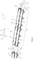
Fig. 1 zeigt einen Kabelkanal 10 zur Aufnahme eines Kabels 12, welches insbesondere als elektrisches Kabel mit einer oder mehreren elektrischen Leitungen ausgebildet ist. Der Kabelkanal 10 weist eine Kombination mehrerer (insbesondere identisch ausgebildeter) Kabelgehäuse 14 auf, welche das Kabel 12 entlang einer axialen Kabellängsrichtung bzw. Kanallängsrichtung 16 zumindest abschnittsweise - hier entlang eines Abschnittes 18 - aufnehmen. Zur Kombination und Aneinanderreihung mehrerer Kabelgehäuse 14 sind mehrere Verbindungsanschlüsse und korrespondierende Gegenanschlüsse an den Kabelgehäusen 14 vorgesehen. - Sämtliche Kabelgehäuse 14 sind zumindest funktionsmäßig und insbesondere auch hinsichtlich ihrer Dimensionierung und geometrischen Abmessungen identisch ausgebildet. Die Verbindungsanschlüsse und korrespondierenden Gegenanschlüsse sind deshalb vorzugsweise an jedem Kabelgehäuse 14 vorhanden.
- Die noch zu beschreibenden Verbindungsanschlüsse und korrespondierenden Gegenanschlüsse sind derart ausgebildet, dass eine Vielzahl von Kabelgehäusen 14 in Kanallängsrichtung 16 und/oder in einer Querrichtung 20 quer zur Kanallängsrichtung 16 aneinandergereiht werden können (
Fig. 1 ,Fig. 2 ). - Bei einem Vergleich zwischen
Fig. 1 undFig. 3 ist erkennbar, dass das Kabelgehäuse 14 zwei miteinander zusammenwirkende Gehäuseschalen 22, 24 aufweist. Eine erste Gehäuseschale des Kabelgehäuses 14 ist als eine Aufnahmeschale 22 zur Aufnahme des Kabels 12 wirksam. Eine zweite Gehäuseschale wirkt dann als eine Deckschale 24 bzw. ein Deckel für einen wirksamen mechanischen Schutz des in die Aufnahmeschale 22 eingelegten Kabels 12. Die Deckschale 24 weist an ihrer Deckaußenseite 26 eine plane Außenfläche 28 auf. Hierdurch kann der gesamte Kabelkanal 10 eine im Wesentlichen plane Deckaußenseite 26 oder Außenfläche aufweisen, was dessen montagetechnische Handhabung erleichtert, z.B. seinen Einbau in ein Fahrzeug. - Nachdem der jeweilige Abschnitt des Kabels 12 in die Aufnahmeschale 22 eingelegt ist (
Fig. 1 ), wird die Deckschale 24 mit der Aufnahmeschale 22 lösbar verbunden, um das Kabelgehäuse 14 zu vervollständigen und einen kanalartigen Hohlraum 23 für das Kabel 12 zu bilden (Fig. 2 ). - In
Fig. 3 ist erkennbar, dass bei der Verbindung der beiden Schalen 22, 24 Montagenasen 30 der Deckschale 24 in Montageaussparungen 32 der Aufnahmeschale 22 eingreifen. Diese Montageelemente 30, 32 sind vorzugsweise derart ausgebildet, dass sie eine lösbare Verbindung (z.B. form- und/oder kraftschlüssig, Verrastung) der beiden Schalen 22, 24 unterstützen. - In
Fig. 1 undFig. 2 sind vier aneinandergereihte Kabelgehäuse 14 sichtbar. Dabei sind je zwei Kabelgehäuse 14 in Kanallängsrichtung 16 aneinandergereiht, so dass zwei parallele Längsreihen 34 gebildet sind. In Querrichtung 20 betrachtet sind ebenfalls je zwei Kabelgehäuse 14 aneinandergereiht, so dass zwei Querreihen 36 gebildet sind. Allerdings sind die Kabelgehäuse 14 der Querreihe 36 montagebedingt in Kanallängsrichtung 16 regelmäßig versetzt angeordnet. - In
Fig. 3 ist erkennbar, dass die Aufnahmeschale 22 an ihrem einen kanallängsseitigen Endabschnitt 38 einen Verbindungsanschluss 40 aufweist, welcher mit einem korrespondierenden Gegenanschluss 42 eines weiteren Endabschnittes 44 der benachbarten Aufnahmeschale 22 lösbar verbunden ist. Die einzelnen Aufnahmeschalen 22 weisen jeweils sowohl den Verbindungsanschluss 40 als auch den korrespondierenden Gegenanschluss 42 auf. Auf diese Weise können beliebig viele Kabelgehäuse 14 in Kanallängsrichtung 16 aneinandergereiht werden. - Sofern an dem jeweiligen Endabschnitt 38, 44 der Aufnahmeschale 22 kein weiteres Kabelgehäuse 14 bzw. keine weitere Aufnahmeschale 22 angereiht wird, ist eine lösbare Verbindung des Verbindungsanschlusses 40 und/oder des korrespondierenden Gegenanschlusses 42 mit einem Abschlussteil 46 vorgesehen. Das Abschlussteil 46 trägt Flankiermittel in Form mehrerer Flankierstege 48 und ggf. zusätzlich eines Flankierringes 50.
- Die Flankierstege 48 sind in einer quer zur Kanallängsrichtung 16 verlaufenden Umfangsrichtung 52 mit Abstand zueinander angeordnet und erstrecken sich im wesentlichen in Kanallängsrichtung 16. Der Flankierring 50 verläuft in Umfangsrichtung 52 und ist radial gesehen teilweise innerhalb und teilweise außerhalb der Flankierstege 48 angeordnet.
- Die vorgenannten Flankiermittel 48, 50 flankieren das Kabel 12 außerhalb des Kabelgehäuses 14 neben dem Endabschnitt 38 oder Endabschnitt 44. Je nach Ausgestaltung können einzelne Flankiermittel 48, 50 das Kabel 12 mit oder ohne radialem Abstand flankieren. Sie tragen dazu bei, dass der von einem oder mehreren Kabelgehäusen 14 aufgenommene Abschnitt 18 des Kabels 12 in der gewünschten Soll-Position bleibt und folglich axial bzw. in Kanallängsrichtung 16 keine wesentlichen Relativbewegungen zwischen dem Abschnitt 18 des Kabels 12 und dem bzw. den aufnehmenden Kabelgehäuse(n) entstehen.
- Zu diesem Zweck ist der Flankierring 50 beispielsweise als ein Kabelbinder ausgebildet, welcher solange festgezurrt wird, bis das Kabel 12 radial an einzelne Flankierstege 48 gepresst ist.
- Die Abschlussteile 46 tragen außerdem dazu bei, dass das Kabel 12 außerhalb der aufgenommenen Abschnitte 18 freie Abschnitte 54 beibehält, welche flexible Biegeabschnitte ergeben für eine flexible Verlegung des gesamten Kabelkanals 10 an dem Einbaubereich, z.B. in einem Fahrzeug.
- In
Fig. 4 ist erkennbar, dass die Aufnahmeschale 22 an ihrer Außenseite 56 mehrere Verbindungsanschlüsse in Form flacher Anschlussausleger 58, welche sich im Wesentlichen in Querrichtung 20 erstrecken. Jeder Anschlussausleger 58 ist von einem Durchgangsloch 60 durchsetzt und korrespondiert mit einem Anschlusszapfen 62, welcher als ein korrespondierender Gegenanschluss an der Außenseite 56 der weiteren Aufnahmeschale 22 angeordnet ist. - Die Anschlussausleger 58 und die korrespondierenden Anschlusszapfen 62 bilden eine montagetechnisch einfache lösbare Verbindung zweier Kabelgehäuse 14 in Querrichtung 20. Eine Lochwand 64 des Durchgangsloches 60 und der korrespondierende Anschlusszapfen 62 liegen nach Art einer Formschlussverbindung aneinander an, welche durch eine in Querrichtung 20 wirksame Federkraft F aufrechterhalten wird. Die Federkraft F wird von mehreren an einer Außenflanke 66 der Aufnahmeschale 22 angeordneten Federblöcken 68 erzeugt. Im Montagezustand der in Querrichtung 20 aneinandergereihten Kabelgehäuse 14 beaufschlagt die Federkraft F der Federblöcke 68 jeweils einen Gegenblock 70. Die Gegenblöcke 70 sind an einer weiteren Außenflanke 72 der Aufnahmeschale 22 angeordnet. Werden die beiden in Querrichtung 20 aneinandergereihten Kabelgehäuse 14 mit einer im Vergleich zur Federkraft F der Federblöcke 68 größeren Gegenkraft in Querrichtung 20 gegeneinander gepresst, kann die lösbare Verbindung 58, 62 aufgelöst werden.
- Wie in
Fig. 3 zu erkennen ist, sind die Federblöcke 68 wie auch die Gegenblöcke 70 in der Aufnahmeschale 22 mit ausbrechbaren Wandungen 74, 76 verschlossen, die sich zur Bildung eines Kabelauslasses bzw. eines zwischen benachbarten Kabelgehäusen 14 verlaufenden geschützten Kabelübergangs von Hand entfernen lassen. Zusätzlich sind in der Deckschale 24 ausbrechbarere Abschnitte 78 vorgesehen, die sich zur Vergrößerung des betreffenden Kabelauslasses bzw. Kabeldurchgangs im Bereich des zugehörigen Federblocks 68 bzw. Gegenblocks 70 ebenfalls entfernen lassen. -
Fig. 5 zeigt die bereits inFig. 4 erkennbare Unterseite des Kabelkanals 10 mit den Außenseiten 56 der Aufnahmeschalen 22. An dieser Unterseite ist eine Leitung 80 lösbar fixiert. Die Leitung 80 ist vorzugsweise als eine Stromschiene, insbesondere Erdungs-Sammelschiene, ausgebildet und trägt hierdurch zur mechanischen Stabilisierung des Kabelkanals 10 bei. - Für die lösbare Fixierung der Leitung 80 sind am Kabelgehäuse 14, genauer gesagt im Bereich der Außenseite 56 der Aufnahmeschale 22, zwei in Kanallängsrichtung 16 äquidistant verlaufende Fixierreihen 82 vorhanden. Jede Fixierreihe 82 weist mehrere in Kanallängsrichtung 16 voneinander beabstandete Fixierelemente 84 auf. Diese sind beispielsweise nach Art von Raststegen ausgebildet, welche in Querrichtung 20 federnd biegsam sein können.
Claims (10)
- Kabelkanal (10) zur Aufnahme mindestens eines Kabels (12), wobei der Kabelkanal (10) eine Kombination mehrerer kanalartiger Kabelgehäuse (14) aufweist, und das Kabelgehäuse (14) mindestens einen Verbindungsanschluss (40, 58) aufweist, welcher mit einem korrespondierenden Gegenanschluss (42, 62) eines weiteren Kabelgehäuses (14) lösbar verbunden ist zur Aneinanderreihung zweier Kabelgehäuse (14).
- Kabelkanal nach Anspruch 1, dadurch gekennzeichnet, dass das Kabelgehäuse (14) sowohl den Verbindungsanschluss (40, 58) als auch den korrespondierenden Gegenanschluss (42, 62) aufweist.
- Kabelkanal nach Anspruch 1 oder 2, dadurch gekennzeichnet, dass der Verbindungsanschluss (40) des Kabelgehäuses (14) und der korrespondierende Gegenanschluss (42) des weiteren Kabelgehäuses (14) lösbar verbunden sind derart, dass zwei Kabelgehäuse (14) in Kanallängsrichtung (16) aneinandergereiht sind.
- Kabelkanal nach einem der vorhergehenden Ansprüche, dadurch gekennzeichnet, dass der Verbindungsanschluss (40) und/oder der korrespondierende Gegenanschluss (42) des Kabelgehäuses (14) jeweils mit einem Abschlussteil (46) lösbar verbunden ist, wobei das Abschlussteil (46) Flankiermittel (48, 50) trägt, welche sich zur radialen Flankierung eines aufgenommenen Kabels (12) in Kanallängsrichtung (16) und/oder in einer quer zur Kanallängsrichtung (16) verlaufenden Umfangsrichtung (52) erstrecken.
- Kabelkanal nach einem der vorhergehenden Ansprüche, dadurch gekennzeichnet, dass der Verbindungsanschluss (58) des Kabelgehäuses (14) und der korrespondierende Gegenanschluss (62) des weiteren Kabelgehäuses (14) lösbar verbunden sind derart, dass zwei Kabelgehäuse (14) quer zur Kanallängsrichtung (16) aneinandergereiht sind.
- Kabelkanal nach Anspruch 5, dadurch gekennzeichnet, dass die lösbare Verbindung durch eine quer zur Kanallängsrichtung (16) zwischen den beiden Kabelgehäusen (14) wirksame Federkraft (F) aufrechterhalten wird.
- Kabelkanal nach einem der vorhergehenden Ansprüche, dadurch gekennzeichnet, dass das Kabelgehäuse (14) zwei miteinander zusammenwirkende Gehäuseschalen (22, 24) aufweist, welche miteinander lösbar verbunden sind und im verbundenen Zustand einen kanalartigen Hohlraum (23) für das Kabel (12) begrenzen.
- Kabelkanal nach Anspruch 7, dadurch gekennzeichnet, dass eine als Deckel wirksame Gehäuseschale (24) eine plane Außenfläche (28) aufweist.
- Kabelkanal nach einem der vorhergehenden Ansprüche, dadurch gekennzeichnet, dass das Kabelgehäuse (14) an einem Außenbereich (56) entlang der Kanallängsrichtung (16) mehrere voneinander beabstandete Fixierelemente (78) trägt zur lösbaren Fixierung einer Leitung (74).
- Kabelkanal nach Anspruch 9, dadurch gekennzeichnet, dass das Kabelgehäuse (14) zwei in Kanallängsrichtung (16) äquidistant verlaufende Fixierreihen (76) mit jeweils mehreren voneinander beabstandeten Fixierelementen (78) aufweist.
Applications Claiming Priority (1)
| Application Number | Priority Date | Filing Date | Title |
|---|---|---|---|
| DE102021124737.3A DE102021124737A1 (de) | 2021-09-24 | 2021-09-24 | Kabelkanal |
Publications (2)
| Publication Number | Publication Date |
|---|---|
| EP4156425A1 true EP4156425A1 (de) | 2023-03-29 |
| EP4156425B1 EP4156425B1 (de) | 2025-12-10 |
Family
ID=83006132
Family Applications (1)
| Application Number | Title | Priority Date | Filing Date |
|---|---|---|---|
| EP22191465.8A Active EP4156425B1 (de) | 2021-09-24 | 2022-08-22 | Kabelkanal |
Country Status (3)
| Country | Link |
|---|---|
| US (1) | US11862951B2 (de) |
| EP (1) | EP4156425B1 (de) |
| DE (1) | DE102021124737A1 (de) |
Citations (8)
| Publication number | Priority date | Publication date | Assignee | Title |
|---|---|---|---|---|
| US6216746B1 (en) * | 2000-02-04 | 2001-04-17 | Hoffman Enclosures, Inc. | Lay-in wireway |
| US20090314541A1 (en) * | 2008-06-20 | 2009-12-24 | Sarah Jean Jones | Expandable power distribution unit |
| WO2012011982A2 (en) * | 2010-04-07 | 2012-01-26 | The Wiremold Company | Customizable bus systems |
| EP1675231B1 (de) * | 2004-12-24 | 2012-05-02 | OBO Bettermann GmbH & Co. KG | Kabeltragvorrichtung |
| EP2725670B1 (de) * | 2012-10-26 | 2014-06-11 | Vezzel AB | Kanalabschnitt zur Herstellung eines Kanals, Kanal und Verfahren zur Bereitstellung und Herstellung eines derartigen Kanals |
| US20160248235A1 (en) * | 2013-10-15 | 2016-08-25 | Sumitomo Wiring Systems, Ltd. | Protector for wire harness |
| WO2020076860A1 (en) * | 2018-10-09 | 2020-04-16 | Uncharted Power, Inc. | A modular container and system of modular containers |
| US20200277739A1 (en) * | 2017-10-03 | 2020-09-03 | Northstone (Ni) Limited | Cable trough |
Family Cites Families (22)
| Publication number | Priority date | Publication date | Assignee | Title |
|---|---|---|---|---|
| US1986965A (en) * | 1929-09-26 | 1935-01-08 | Bulldog Electric Prod Co | Wiring duct and fittings |
| NL253817A (de) * | 1959-07-21 | 1900-01-01 | Burndy Corp | |
| US3633628A (en) * | 1970-01-02 | 1972-01-11 | Avis Ind Corp | Wireway divider |
| US3951439A (en) * | 1972-09-25 | 1976-04-20 | Hancor, Inc. | Modular cellular conduit assembly |
| US4035051A (en) * | 1976-10-19 | 1977-07-12 | Western Electric Company, Inc. | Adjustable molded hood assembly for a cable connector plug |
| JPS63198324U (de) * | 1987-06-09 | 1988-12-21 | ||
| US5024251A (en) * | 1990-01-18 | 1991-06-18 | Square D Company | Lay-in wireway assembly |
| US5399812A (en) * | 1993-05-24 | 1995-03-21 | Chrysler Corporation | Housing for supporting and routing cables |
| US5534665A (en) * | 1994-04-29 | 1996-07-09 | General Motors Corporation | Wiring harness shroud |
| US5887831A (en) * | 1997-08-04 | 1999-03-30 | Post; Robert E. | Roof cable support system |
| JP3613445B2 (ja) * | 1999-05-18 | 2005-01-26 | 矢崎総業株式会社 | バッテリ接続プレート |
| JP2001128334A (ja) * | 1999-10-29 | 2001-05-11 | Yazaki Corp | 電線プロテクタの電線保持構造 |
| US6523791B2 (en) * | 2000-06-01 | 2003-02-25 | Panduit Corp. | Cable duct coupler |
| US7964804B2 (en) * | 2008-12-15 | 2011-06-21 | Multilink, Inc. | Exterior raceway system for cables |
| DE102009017319A1 (de) * | 2009-04-16 | 2010-10-21 | Airbus Deutschland Gmbh | Kabelführungsvorrichtung für einen in einer Flugzeugkabine verlegten elektrischen Kabelstrang |
| US8534613B2 (en) * | 2010-09-17 | 2013-09-17 | Terry D. Wurzer | Expansion joint for a cable tray apparatus for a people mover system |
| JP5768379B2 (ja) * | 2011-01-19 | 2015-08-26 | 住友電装株式会社 | ワイヤハーネス用のプロテクタ |
| JP5809465B2 (ja) * | 2011-07-05 | 2015-11-11 | 矢崎総業株式会社 | 電線配索装置 |
| JP5973262B2 (ja) * | 2012-07-09 | 2016-08-23 | 矢崎総業株式会社 | バスバモジュール |
| JP6793047B2 (ja) * | 2017-01-25 | 2020-12-02 | 矢崎総業株式会社 | プロテクタおよびワイヤハーネス |
| DE102019201339A1 (de) | 2019-02-01 | 2020-08-06 | Deere & Company | Leiteranordnung für eine elektrische Energie- und/oder Datenübertragungsverbindung |
| US11433830B2 (en) | 2020-10-01 | 2022-09-06 | Deere & Company | Wire harness tray assembly |
-
2021
- 2021-09-24 DE DE102021124737.3A patent/DE102021124737A1/de active Pending
-
2022
- 2022-07-20 US US17/813,729 patent/US11862951B2/en active Active
- 2022-08-22 EP EP22191465.8A patent/EP4156425B1/de active Active
Patent Citations (8)
| Publication number | Priority date | Publication date | Assignee | Title |
|---|---|---|---|---|
| US6216746B1 (en) * | 2000-02-04 | 2001-04-17 | Hoffman Enclosures, Inc. | Lay-in wireway |
| EP1675231B1 (de) * | 2004-12-24 | 2012-05-02 | OBO Bettermann GmbH & Co. KG | Kabeltragvorrichtung |
| US20090314541A1 (en) * | 2008-06-20 | 2009-12-24 | Sarah Jean Jones | Expandable power distribution unit |
| WO2012011982A2 (en) * | 2010-04-07 | 2012-01-26 | The Wiremold Company | Customizable bus systems |
| EP2725670B1 (de) * | 2012-10-26 | 2014-06-11 | Vezzel AB | Kanalabschnitt zur Herstellung eines Kanals, Kanal und Verfahren zur Bereitstellung und Herstellung eines derartigen Kanals |
| US20160248235A1 (en) * | 2013-10-15 | 2016-08-25 | Sumitomo Wiring Systems, Ltd. | Protector for wire harness |
| US20200277739A1 (en) * | 2017-10-03 | 2020-09-03 | Northstone (Ni) Limited | Cable trough |
| WO2020076860A1 (en) * | 2018-10-09 | 2020-04-16 | Uncharted Power, Inc. | A modular container and system of modular containers |
Also Published As
| Publication number | Publication date |
|---|---|
| EP4156425B1 (de) | 2025-12-10 |
| DE102021124737A1 (de) | 2023-03-30 |
| US11862951B2 (en) | 2024-01-02 |
| US20230094816A1 (en) | 2023-03-30 |
Similar Documents
| Publication | Publication Date | Title |
|---|---|---|
| EP0396936B1 (de) | Einrichtung zum Schutz elektrischer Anlagen | |
| EP2091111B1 (de) | Kontaktierungssystem für Lichtbänder oder Leuchten | |
| DE2358863C3 (de) | Vorrichtung zum Verbinden von Kabelwannenabschnitten | |
| DE202009014251U1 (de) | System zur Verbindung elektrischer Leiter mit voneinander verschiedenen Potentialen sowie Steckadapter für das System | |
| EP3592990B1 (de) | Steuereinrichtung | |
| DE102014213973A1 (de) | Verbinderanordnung zum mechanisch flexiblen elektrischen Verbinden zweier Hochspannungskomponenten in einem Fahrzeug | |
| EP4156425B1 (de) | Kabelkanal | |
| DE102016112758A1 (de) | Halteteil und verfahren zum befestigen von elektrischen leitungen sowie leitungsanordnng in einem fahrzeug | |
| DE102024110871B3 (de) | Elektrische Installation mit einer Anordnung für die berührungssichere Kontaktierung mehrerer Stromsammelschienen mit Kabeldurchführung | |
| WO2018108498A1 (de) | Entkopplungselement zur verbindung einer leistungselektronik mit einer elektrischen maschine | |
| DE202012101656U1 (de) | Kabelverbindungsvorrichtung für ein Kabel | |
| DE102017116679A1 (de) | Kabelkanal | |
| EP0709252B1 (de) | Insbesondere für den Einbau in Kraftfahrzeugkarosserien bestimmter Kabelbaum | |
| DE202010009722U1 (de) | Kabel- und Leitungsführung | |
| DE102015218747A1 (de) | HV-Kabel-Anschlussanordnung | |
| AT405000B (de) | Feldabstandhalter für hochspannungs-freileitungen mit bündelleitern | |
| EP3996207A1 (de) | Erdungsschelle mit verdrehschutz | |
| EP2548209B1 (de) | Leitungsführungssystem für einen hochspannungstransformator | |
| DE102018114520B4 (de) | Leitungsführungselement und Maschinenvorrichtung | |
| DE102008011762A1 (de) | Elektrischer Steckverbinder | |
| DE102021133811B4 (de) | Kabelkanal für automatisierte Verdrahtung einer elektrischen Steuerungs- oder Schaltanlage | |
| EP4094329B1 (de) | Leuchtensystem mit mechanischem sperrelement | |
| EP3336986A1 (de) | Vorrichtung zum führen von mindestens zwei leitungen sowie ein anschlussmaterial umfassend eine solche vorrichtung | |
| EP0697751A1 (de) | Abzweigdose | |
| DE102020129438A1 (de) | Energiespeicher sowie Kraftfahrzeug |
Legal Events
| Date | Code | Title | Description |
|---|---|---|---|
| PUAI | Public reference made under article 153(3) epc to a published international application that has entered the european phase |
Free format text: ORIGINAL CODE: 0009012 |
|
| STAA | Information on the status of an ep patent application or granted ep patent |
Free format text: STATUS: THE APPLICATION HAS BEEN PUBLISHED |
|
| AK | Designated contracting states |
Kind code of ref document: A1 Designated state(s): AL AT BE BG CH CY CZ DE DK EE ES FI FR GB GR HR HU IE IS IT LI LT LU LV MC MK MT NL NO PL PT RO RS SE SI SK SM TR |
|
| STAA | Information on the status of an ep patent application or granted ep patent |
Free format text: STATUS: REQUEST FOR EXAMINATION WAS MADE |
|
| 17P | Request for examination filed |
Effective date: 20230929 |
|
| RBV | Designated contracting states (corrected) |
Designated state(s): AL AT BE BG CH CY CZ DE DK EE ES FI FR GB GR HR HU IE IS IT LI LT LU LV MC MK MT NL NO PL PT RO RS SE SI SK SM TR |
|
| GRAP | Despatch of communication of intention to grant a patent |
Free format text: ORIGINAL CODE: EPIDOSNIGR1 |
|
| STAA | Information on the status of an ep patent application or granted ep patent |
Free format text: STATUS: GRANT OF PATENT IS INTENDED |
|
| RIC1 | Information provided on ipc code assigned before grant |
Ipc: H02G 3/06 20060101AFI20250813BHEP Ipc: H02G 3/04 20060101ALI20250813BHEP Ipc: H02G 3/34 20060101ALI20250813BHEP Ipc: B60R 16/02 20060101ALN20250813BHEP |
|
| INTG | Intention to grant announced |
Effective date: 20250821 |
|
| GRAS | Grant fee paid |
Free format text: ORIGINAL CODE: EPIDOSNIGR3 |
|
| GRAA | (expected) grant |
Free format text: ORIGINAL CODE: 0009210 |
|
| STAA | Information on the status of an ep patent application or granted ep patent |
Free format text: STATUS: THE PATENT HAS BEEN GRANTED |
|
| AK | Designated contracting states |
Kind code of ref document: B1 Designated state(s): AL AT BE BG CH CY CZ DE DK EE ES FI FR GB GR HR HU IE IS IT LI LT LU LV MC MK MT NL NO PL PT RO RS SE SI SK SM TR |
|
| REG | Reference to a national code |
Ref country code: CH Ref legal event code: F10 Free format text: ST27 STATUS EVENT CODE: U-0-0-F10-F00 (AS PROVIDED BY THE NATIONAL OFFICE) Effective date: 20251210 Ref country code: GB Ref legal event code: FG4D Free format text: NOT ENGLISH |
|
| REG | Reference to a national code |
Ref country code: DE Ref legal event code: R096 Ref document number: 502022006366 Country of ref document: DE |
|
| REG | Reference to a national code |
Ref country code: IE Ref legal event code: FG4D Free format text: LANGUAGE OF EP DOCUMENT: GERMAN |
|
| PG25 | Lapsed in a contracting state [announced via postgrant information from national office to epo] |
Ref country code: ES Free format text: LAPSE BECAUSE OF FAILURE TO SUBMIT A TRANSLATION OF THE DESCRIPTION OR TO PAY THE FEE WITHIN THE PRESCRIBED TIME-LIMIT Effective date: 20251210 |
|
| REG | Reference to a national code |
Ref country code: LT Ref legal event code: MG9D |
|
| PG25 | Lapsed in a contracting state [announced via postgrant information from national office to epo] |
Ref country code: NO Free format text: LAPSE BECAUSE OF FAILURE TO SUBMIT A TRANSLATION OF THE DESCRIPTION OR TO PAY THE FEE WITHIN THE PRESCRIBED TIME-LIMIT Effective date: 20260310 |
|
| PG25 | Lapsed in a contracting state [announced via postgrant information from national office to epo] |
Ref country code: FI Free format text: LAPSE BECAUSE OF FAILURE TO SUBMIT A TRANSLATION OF THE DESCRIPTION OR TO PAY THE FEE WITHIN THE PRESCRIBED TIME-LIMIT Effective date: 20251210 Ref country code: HR Free format text: LAPSE BECAUSE OF FAILURE TO SUBMIT A TRANSLATION OF THE DESCRIPTION OR TO PAY THE FEE WITHIN THE PRESCRIBED TIME-LIMIT Effective date: 20251210 |
|
| REG | Reference to a national code |
Ref country code: NL Ref legal event code: MP Effective date: 20251210 |
|
| PG25 | Lapsed in a contracting state [announced via postgrant information from national office to epo] |
Ref country code: RS Free format text: LAPSE BECAUSE OF FAILURE TO SUBMIT A TRANSLATION OF THE DESCRIPTION OR TO PAY THE FEE WITHIN THE PRESCRIBED TIME-LIMIT Effective date: 20260310 |
|
| PG25 | Lapsed in a contracting state [announced via postgrant information from national office to epo] |
Ref country code: LV Free format text: LAPSE BECAUSE OF FAILURE TO SUBMIT A TRANSLATION OF THE DESCRIPTION OR TO PAY THE FEE WITHIN THE PRESCRIBED TIME-LIMIT Effective date: 20251210 |
|
| PG25 | Lapsed in a contracting state [announced via postgrant information from national office to epo] |
Ref country code: BG Free format text: LAPSE BECAUSE OF FAILURE TO SUBMIT A TRANSLATION OF THE DESCRIPTION OR TO PAY THE FEE WITHIN THE PRESCRIBED TIME-LIMIT Effective date: 20251210 |