EP4156325A1 - Lithiumelektrode - Google Patents
Lithiumelektrode Download PDFInfo
- Publication number
- EP4156325A1 EP4156325A1 EP22189884.4A EP22189884A EP4156325A1 EP 4156325 A1 EP4156325 A1 EP 4156325A1 EP 22189884 A EP22189884 A EP 22189884A EP 4156325 A1 EP4156325 A1 EP 4156325A1
- Authority
- EP
- European Patent Office
- Prior art keywords
- layer
- electrically conductive
- lithium
- recess
- conductive structure
- Prior art date
- Legal status (The legal status is an assumption and is not a legal conclusion. Google has not performed a legal analysis and makes no representation as to the accuracy of the status listed.)
- Granted
Links
Images

Classifications
-
- H—ELECTRICITY
- H01—ELECTRIC ELEMENTS
- H01M—PROCESSES OR MEANS, e.g. BATTERIES, FOR THE DIRECT CONVERSION OF CHEMICAL ENERGY INTO ELECTRICAL ENERGY
- H01M4/00—Electrodes
- H01M4/02—Electrodes composed of, or comprising, active material
- H01M4/64—Carriers or collectors
- H01M4/70—Carriers or collectors characterised by shape or form
- H01M4/80—Porous plates, e.g. sintered carriers
-
- H—ELECTRICITY
- H01—ELECTRIC ELEMENTS
- H01M—PROCESSES OR MEANS, e.g. BATTERIES, FOR THE DIRECT CONVERSION OF CHEMICAL ENERGY INTO ELECTRICAL ENERGY
- H01M10/00—Secondary cells; Manufacture thereof
- H01M10/05—Accumulators with non-aqueous electrolyte
- H01M10/052—Li-accumulators
-
- H—ELECTRICITY
- H01—ELECTRIC ELEMENTS
- H01M—PROCESSES OR MEANS, e.g. BATTERIES, FOR THE DIRECT CONVERSION OF CHEMICAL ENERGY INTO ELECTRICAL ENERGY
- H01M10/00—Secondary cells; Manufacture thereof
- H01M10/05—Accumulators with non-aqueous electrolyte
- H01M10/056—Accumulators with non-aqueous electrolyte characterised by the materials used as electrolytes, e.g. mixed inorganic/organic electrolytes
- H01M10/0561—Accumulators with non-aqueous electrolyte characterised by the materials used as electrolytes, e.g. mixed inorganic/organic electrolytes the electrolyte being constituted of inorganic materials only
- H01M10/0562—Solid materials
-
- H—ELECTRICITY
- H01—ELECTRIC ELEMENTS
- H01M—PROCESSES OR MEANS, e.g. BATTERIES, FOR THE DIRECT CONVERSION OF CHEMICAL ENERGY INTO ELECTRICAL ENERGY
- H01M10/00—Secondary cells; Manufacture thereof
- H01M10/05—Accumulators with non-aqueous electrolyte
- H01M10/056—Accumulators with non-aqueous electrolyte characterised by the materials used as electrolytes, e.g. mixed inorganic/organic electrolytes
- H01M10/0564—Accumulators with non-aqueous electrolyte characterised by the materials used as electrolytes, e.g. mixed inorganic/organic electrolytes the electrolyte being constituted of organic materials only
- H01M10/0566—Liquid materials
-
- H—ELECTRICITY
- H01—ELECTRIC ELEMENTS
- H01M—PROCESSES OR MEANS, e.g. BATTERIES, FOR THE DIRECT CONVERSION OF CHEMICAL ENERGY INTO ELECTRICAL ENERGY
- H01M10/00—Secondary cells; Manufacture thereof
- H01M10/05—Accumulators with non-aqueous electrolyte
- H01M10/058—Construction or manufacture
-
- H—ELECTRICITY
- H01—ELECTRIC ELEMENTS
- H01M—PROCESSES OR MEANS, e.g. BATTERIES, FOR THE DIRECT CONVERSION OF CHEMICAL ENERGY INTO ELECTRICAL ENERGY
- H01M4/00—Electrodes
- H01M4/02—Electrodes composed of, or comprising, active material
- H01M4/13—Electrodes for accumulators with non-aqueous electrolyte, e.g. for lithium-accumulators; Processes of manufacture thereof
- H01M4/134—Electrodes based on metals, Si or alloys
-
- H—ELECTRICITY
- H01—ELECTRIC ELEMENTS
- H01M—PROCESSES OR MEANS, e.g. BATTERIES, FOR THE DIRECT CONVERSION OF CHEMICAL ENERGY INTO ELECTRICAL ENERGY
- H01M4/00—Electrodes
- H01M4/02—Electrodes composed of, or comprising, active material
- H01M4/36—Selection of substances as active materials, active masses, active liquids
- H01M4/38—Selection of substances as active materials, active masses, active liquids of elements or alloys
- H01M4/381—Alkaline or alkaline earth metals elements
- H01M4/382—Lithium
-
- H—ELECTRICITY
- H01—ELECTRIC ELEMENTS
- H01M—PROCESSES OR MEANS, e.g. BATTERIES, FOR THE DIRECT CONVERSION OF CHEMICAL ENERGY INTO ELECTRICAL ENERGY
- H01M6/00—Primary cells; Manufacture thereof
- H01M6/40—Printed batteries, e.g. thin film batteries
-
- H—ELECTRICITY
- H01—ELECTRIC ELEMENTS
- H01M—PROCESSES OR MEANS, e.g. BATTERIES, FOR THE DIRECT CONVERSION OF CHEMICAL ENERGY INTO ELECTRICAL ENERGY
- H01M4/00—Electrodes
- H01M4/02—Electrodes composed of, or comprising, active material
- H01M2004/021—Physical characteristics, e.g. porosity, surface area
-
- H—ELECTRICITY
- H01—ELECTRIC ELEMENTS
- H01M—PROCESSES OR MEANS, e.g. BATTERIES, FOR THE DIRECT CONVERSION OF CHEMICAL ENERGY INTO ELECTRICAL ENERGY
- H01M2300/00—Electrolytes
- H01M2300/0017—Non-aqueous electrolytes
- H01M2300/0065—Solid electrolytes
- H01M2300/0068—Solid electrolytes inorganic
- H01M2300/0071—Oxides
-
- H—ELECTRICITY
- H01—ELECTRIC ELEMENTS
- H01M—PROCESSES OR MEANS, e.g. BATTERIES, FOR THE DIRECT CONVERSION OF CHEMICAL ENERGY INTO ELECTRICAL ENERGY
- H01M2300/00—Electrolytes
- H01M2300/0017—Non-aqueous electrolytes
- H01M2300/0065—Solid electrolytes
- H01M2300/0068—Solid electrolytes inorganic
- H01M2300/008—Halides
-
- Y—GENERAL TAGGING OF NEW TECHNOLOGICAL DEVELOPMENTS; GENERAL TAGGING OF CROSS-SECTIONAL TECHNOLOGIES SPANNING OVER SEVERAL SECTIONS OF THE IPC; TECHNICAL SUBJECTS COVERED BY FORMER USPC CROSS-REFERENCE ART COLLECTIONS [XRACs] AND DIGESTS
- Y02—TECHNOLOGIES OR APPLICATIONS FOR MITIGATION OR ADAPTATION AGAINST CLIMATE CHANGE
- Y02E—REDUCTION OF GREENHOUSE GAS [GHG] EMISSIONS, RELATED TO ENERGY GENERATION, TRANSMISSION OR DISTRIBUTION
- Y02E60/00—Enabling technologies; Technologies with a potential or indirect contribution to GHG emissions mitigation
- Y02E60/10—Energy storage using batteries
Definitions
- the present invention is related to an electrode, in particular to a lithium electrode adapted for lithium-ion secondary batteries.
- the lithium battery system Comparing to the current non-lithium battery system, the lithium battery system has advantages of high operation voltage (up to 3.6V), high energy density (up to 120Wh/kg), light weight, longer cycle life, friendly to the environment and so on.
- the earliest lithium battery developed is the rechargeable lithium metal battery which has pretty high energy density but meanwhile has serious issues of stability and safety because of the high chemical reacting ability to the electrolyte.
- the developments of the rechargeable lithium battery gradually focus on replacing the organic solvent with the polymer electrolyte.
- the capacity of the battery system becomes the important developing issue again.
- the development of the lithium metal battery system was suspended due to its safety issue. Comparing to the lithium-ion and the lithium polymer systems, the energy density of the lithium metal system is much higher than other systems. However, because the lithium metal has high chemical activity, an extreme oxidation-reduction reaction occurs if the lithium metal is not stored or operated under the proper condition. Practically, the lithium metal battery system is quite suitable for the current smart electrical device only if the issues of safety, processing and storage of the lithium metal can be conquered.
- lithium dendritic crystals which are called lithium dendrites.
- the lithium dendrites gradually grow, they may break to form dead lithium resulting in irreversible capacity losses. More seriously, the lithium dendrites may pierce through the separator, causing internal short circuits and battery explosions.
- lithium is an extremely reactive material, it may react with the electrolyte to consume active lithium and cause potential safety issues.
- a lithium electrode is provided to overcome the above problems.
- the lithium dendrites are constrained to plate in a specific region by the arrangement of the electrically conductive structure layer and the solid electrolyte layer.
- the solid electrolyte layer and the electrolyte storage layer which is disposed above the solid electrolyte layer efficiently inhibit the height of plating of the lithium dendrite during charging due to the structural strength thereof.
- the lithium dendrite will mainly plate horizontally to prevent to penetrate through the electrical insulator, i.e. the separator, to avoid inner shorting. Meanwhile, the lithium dendrites are constrained to plate toward the vertical direction so that the thickness of the battery will not vary extremely.
- the lithium dendrites only can push the solid electrolyte layer toward the electrolyte storage layer during plating and stripping of the lithium dendrites.
- the electrolyte storage layer would be pressed or released to make the liquid or gel electrolyte impregnated therein outflow and inflow.
- the liquid or gel electrolyte impregnated in the electrolyte storage layer does not contact to the negative active material, the lithium metal layer, to avoid the liquid or gel electrolyte being decomposed and reduce the irreversible capacity losses.
- this invention discloses a lithium electrode, which includes an electrically conductive structure layer, a lithium metal layer, a solid electrolyte layer, an electrolyte storage layer and a porous covering layer.
- the electrically conductive structure layer has at least one recess with one-side opening and an inner surface of the recess has at least one electrically conductive region and at least one electrically insulating region.
- the lithium metal layer is disposed in the recess of the electrically conductive structure layer and contacts to the electrically conductive region.
- the solid electrolyte layer and the electrolyte storage layer are disposed thereon sequentially.
- the porous covering layer is disposed on the electrically conductive structure layer to cover the opening of the recess.
- the electrolyte storage layer impregnated with the liquid or gel electrolyte does not contact to the lithium metal layer, due to the existence of the solid electrolyte layer.
- the lithium dendrites when the lithium dendrites are grown from the lithium metal layer, the lithium dendrites would be directly suppressed by the solid electrolyte layer.
- the solid electrolyte layer is constrained by the electrolyte storage layer disposed above. Therefore, the lithium dendrites only can push the solid electrolyte layer toward and press the electrolyte storage layer.
- the lithium dendrites will be constrained to plate in a specific region and mainly plate horizontally.
- the electrical insulator, i.e. the separator would not be penetrated through by the lithium dendrites to avoid inner shorting.
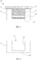
- FIG. 1 is a schematic diagram of the lithium electrode of this invention.
- the lithium electrode 10 of this invention includes an electrically conductive structure 11, a lithium metal layer 12, a solid electrolyte layer 13, an electrolyte storage layer 14 and a porous covering layer 15.
- the electrically conductive structure layer 11 has at least one recess 111 with one-side opening.
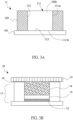
- FIG. 2 is a schematic diagram of the electrically conductive structure layer of the lithium electrode according to FIG. 1 of this invention.
- the width of the opening of the recess 111 is greater than 0 or not less than 50 micrometers, preferably. The maximum available value is depended on the active range of the battery. Also, the depth of the recess 111 ranges from 15 to 40 micrometers
- the inner surface of the recess 111 has at least one electrically conductive region 113 and at least one electrically insulating region 112.
- the lithium metal layer 12 is disposed in the recess 111 of the electrically conductive structure layer 11 and contacts to the electrically conductive region 113.
- the thickness of the lithium metal layer 12 ranges from 0.3 to 5 micrometers.
- the solid electrolyte layer 13 is movably disposed in the recess 111 of the electrically conductive structure layer 11.
- the bottom of the solid electrolyte layer 13 covers and contacts to the lithium metal layer 12, and the sides of the solid electrolyte layer 13 are contacted with the electrically insulating region 112.
- the electrolyte storage layer 14 is disposed in the recess 111 of the electrically conductive structure layer 11.
- the bottom of the electrolyte storage layer 14 covers and contacts to the solid electrolyte layer 13, and the sides of the electrolyte storage layer 14 are contacted with the electrically insulating region 112.
- the porous covering layer 15 is disposed on the electrically conductive structure layer 11 to cover the opening of the recess 111 of the electrically conductive structure layer 11.
- the porous covering layer 15 has a plurality of through holes to allow lithium ions to pass.
- An adhesive layer 16 is disposed between the electrically conductive structure layer 11 and the porous covering layer 15 to adhere the porous covering layer 15 to the electrically conductive structure layer 11.
- the liquid and/or gel electrolyte are impregnated in the electrolyte storage layer 14.
- the material of the solid electrolyte layer 13 may be any solid electrolyte series, such as oxide-based solid electrolyte, sulfide-based solid electrolyte, lithium-aluminum alloy solid electrolyte or lithium azide (LiN 3 ) solid electrolyte, which may be crystalline or glassy.
- the lithium metal layer 12 and the electrolyte storage layer 14 are separated by the solid electrolyte layer 13. Therefore, the unnecessary contact between the liquid or gel electrolyte impregnated in the electrolyte storage layer 14 and the active material, the lithium metal layer 12 are reduced or avoided.
- the unnecessary consumption for the lithium ions are also reduced or avoided to prevent the performance attenuation of the lithium batteries.
- the lithium metal layer 12 is completely covered by the solid electrolyte layer 13.
- the side edges of the solid electrolyte layer 13 abuts against the side walls of the recess 111 to reduce or avoid the unnecessary contact between the liquid or gel electrolyte impregnated in the electrolyte storage layer 14 and the lithium metal layer 12.
- the lithium metal layer 12 is disposed at the bottom of the recess 111. Therefore, the bottom of the recess 111 is the electrically conductive region 113.
- the electricity generated during the electrochemical reaction is outputted from the electrically conductive region 113. It is necessary that the electrically conductive region 113 is with an electrical conductive path between the inside and the outside of the battery.
- the solid electrolyte layer 13 and the electrolyte storage layer 14 have to contact with the electrically insulating region 112 of the recess 111. Therefore, the side walls of the recess 111 are the electrically insulating region 112.
- the shape of the recess 111 of the electrically conductive structure layer 11 is not limited. As shown in FIG. 2 , the side walls of the recess 111 is, but not limited to, vertical. Excepting for the above-mentioned requirements, it has to be considered that the solid electrolyte layer 13 is moveable to suppress the growth of the lithium dendrites, which only can push the solid electrolyte layer 13 to press the electrolyte storage layer 14. A more detailed description of the present invention is presented below. Therefore, the side walls, for arrangement of the solid electrolyte layer 13, of the recess 111 are preferably smooth and equidistant.
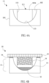
- FIG. 3A is a schematic diagram of a first embodiment of the electrically conductive structure layer of the lithium electrode of this invention.
- an electrically conductive element 101 is the main body of the electrically conductive structure layer 11.
- An electrically insulating element 102 is disposed directly on the top surface of the electrically conductive element 101.
- the electrically insulating element 102 has at least one through hole 102h. Parts of the electrically conductive element 101 are exposed from the through hole 102h. Therefore, the recess 111 with one-side opening is formed thereof.
- the bottom 111b of the recess 111 is formed by the electrically conductive element 101 to be defined as the electrically conductive region 113.
- the side wall 111w of the recess 111 is formed by the electrically insulating element 102 to be defined as the electrically insulating region 112.
- the lithium electrode 10 constructed by the electrically conductive structure layer 11 based on the first embodiment is illustrated in FIG. 3B .
- the bottom 111b of the recess 111 is formed by the electrically conductive element 101. Therefore, an electrical conductive path between the inside and the outside of the battery can be formed to output the electricity generated thereof. That means the electrically conductive element 101 serving the current collector of the lithium electrode 10.
- the material of the electrically conductive element 101 may be metal or any other electrically conductive materials, such as copper, nickel, steel or any combinations thereof.
- the material of the electrically insulating element 102 may be insulating polymer material, insulating ceramic material, insulating glass material, insulating glass fiber material and any combinations thereof.
- the insulating polymer material includes polyimide, polyethylene terephthalate, polyurethane, polyacrylate, epoxy or silicone.
- the insulating glass fiber material may be FR4-class, such as FR4 epoxy glass fiber material.
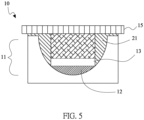
- FIGS. 4A and 4B is a schematic diagram of a second embodiment of the electrically conductive structure layer of the lithium electrode of this invention, and a schematic diagram of the lithium electrode based on the second embodiment of the electrically conductive structure layer shown in FIG. 4A of this invention respectively.
- the electrically conductive structure layer 11 of this second embodiment also includes an electrically conductive element 101 and an electrically insulating element 102. More specifically, the electrically conductive element 101 has a blind hole 101b to form the recess 111 directly.
- the electrically insulating element 102 is disposed on a side wall of the blind hole 101b to be defined as the electrically insulating region 112.
- a bottom of the blind hole 101b is uncovered by the electrically insulating element 102 and defined as the electrically conductive region 113. Similar, the electrically conductive element 101 is the main body of the electrically conductive structure layer 11. The uncovered bottom of the recess 111 is formed by the electrically conductive element 101. Therefore, an electrical conductive path between the inside and the outside of the battery can be formed to output the electricity generated by the battery constructed by lithium electrode 10. Also, the electrically conductive element 101 can be regarded as the current collector of the lithium electrode 10.
- the electrolyte storage layer 14 contacts and covers the solid electrolyte layer 13.
- the top surface of the electrolyte storage layer 14 is substantially aligned with the top surface of the electrically conductive structure layer 11. In other words, the remaining space is filled by the electrolyte storage layer 14.
- the electrolyte storage layer 14 is used to impregnate with the liquid and/or gel electrolyte. In this invention, the lithium metal layer 12 and the electrolyte storage layer 14 are separated by the solid electrolyte layer 13.
- the unnecessary contact between the liquid or gel electrolyte impregnated in the electrolyte storage layer 14 and the active material (i.e. the lithium metal layer 12) are reduced or avoided.
- the unnecessary consumption for the lithium ions are also reduced or avoided to prevent the performance attenuation of the lithium batteries.
- the electrolyte storage layer 14 is porous to impregnate with the liquid and/or gel electrolyte.
- the material of the electrolyte storage layer 14 may be polymer material, ceramic material, glass material, fiber material and any combinations thereof.
- the porous structure of the electrolyte storage layer 14 is formed by stacked particles and/or crossed fibers.
- the particles include ceramic particles, polymer particles and/or glass particles.
- the fibers include polymer fibers and/or glass fibers.
- the porous covering layer 15 is adhered to the electrically conductive structure layer 11 to cover the opening of the recess 111.
- the porous covering layer 15 has a plurality of through holes to allow lithium ions and the electrolyte to pass for the electrochemical reactions.
- the through holes may be linear or non-linear (ant holes) formed by chemical or mechanical processes.
- the porous covering layer 15 may be made of porous materials to offer the through holes.
- the adhesive layer 16, located between the electrically conductive structure layer 11 and the porous covering layer 15, and the electrically insulating element 102 are integrated into an electrically insulating glue frame 21.
- the electrically insulating glue frame 21 is formed between the porous covering layer 15 and the electrically conductive element 101.
- the electrically insulating glue frame 21 located on the side walls of the recess 111 is used for the electrically insulating element 102 to define as the electrically insulating region 112.
- the electrically insulating glue frame 21 located between the electrically conductive structure layer 11 and the porous covering layer 15 is used to adhere the electrically conductive structure layer 11 and the porous covering layer 15.
- the material of the electrically insulating glue frame 21 is selected from the group consisting of thermosetting polymer, thermoplastic polymer and any combinations thereof.
- the thermosetting polymer is selected from the group consisting of silicone, epoxy, acrylic acid resin and any combinations thereof and the thermoplastic polymer is selected from the group consisting of polyethylene, polypropylene, thermoplastic polyimide, thermoplastic polyurethane and any combinations thereof.
- the material of the electrically insulating glue frame 21 is preferably selected from the electrolyte-inert material, such as silicone, polyethylene, polypropylene, thermoplastic polyimide and so on. Therefore, the electrically insulating glue frame 21 will not react with the electrolyte to maintain the adhesion ability.
- the adhesive layer 16 and the electrically insulating element 102 may be integrated into an electrically insulating glue frame 21.
- the electrically insulating glue frame 21 is used for the electrically insulating element 102 of the recess 111 and is used to adhere the electrically conductive structure layer 11 and the porous covering layer 15.
- the electrically insulating glue frame 21 may be multi-layered structure. With the modification of the adhesive material, the adhesive will be better.
- the lithium dendrites when the lithium metal is plated, the lithium dendrites will grow vertically. With the arrangement of this invention, the growth of the lithium dendrites is constrained by the solid electrolyte layer 13. The vertical growth of the lithium dendrites will push the solid electrolyte layer 13. The solid electrolyte layer 13 is moveably disposed in the recess 111. Therefore, the solid electrolyte layer 13 is pushed to move toward the electrolyte storage layer 14. Due the porous covering layer 15 is adhered on the electrically conductive structure layer 11 firmly, the movement range of the solid electrolyte layer 13 is limited. The electrolyte storage layer 14 is porous to store the liquid and/or gel electrolyte. Also, the electrolyte storage layer 14 is compressible.
- the electrolyte storage layer 14 When the electrolyte storage layer 14 is pressed by the solid electrolyte layer 13, the electrolyte storage layer 14 will be deformed to squeeze out parts of the liquid and/or gel electrolyte impregnated therein. Also, the compressibility of the electrolyte storage layer 14 is limited. As the compression distance increases, the resistive force to compress the electrolyte storage layer 14 will become larger to inhibit the vertical growth of the lithium dendrites. The lithium dendrites are forced to grow in a horizontal direction. The penetration through issue for the electrical insulator, i.e. the separator, caused by the lithium dendrites can be eliminated to avoid inner shorting.
- the electrical insulator i.e. the separator
- the sulfide -based solid electrolyte may be selected from one or more of the groups consisting of a glassy state of Li 2 S-P 2 S 5 , a crystalline state of Li x' M y' PS z' , and a glassy ceramic state of Li 2 S-P 2 S 5 .
- M is selected from one or more of the groups consisting of Si, Ge, and Sn;
- x ′ + 4 y ′ + 5 2 Z ′ , 0 ⁇ y ′ ⁇ 1 .
- the glassy state of Li 2 S-P 2 S 5 may be selected from one or more of the groups consisting of glassy state of 70Li 2 S-30P 2 S 5 , glassy state of 75Li 2 S-25P 2 S 5 , and glassy state of 80Li 2 S-20P 2 S 5 .
- the glassy ceramic state of Li 2 S-P 2 S 5 may be selected from one or more of the groups consisting of glassy ceramic state of 70Li 2 S-30P 2 S 5 , glassy ceramic state of 75Li 2 S-25P 2 S 5 , and glassy ceramic state of 80Li 2 S-20P 2 S 5 .
- the crystalline state of Li x' M y' PS z' Li x' M y' PS z' may be selected from one or more of the groups consisting of Li 3 PS 4 , Li 4 SnS 4 , Li 4 GeS 4 , Li 10 SnP 2 S 12 , Li 10 GeP 4 S 12 , Li 10 SiP 2 S 12 , Li 10 GeP 2 S 12 , Li 7 P 3 S 11 , L 9.5 4Si 1.74 P 1.44 S 11.7 Cl 0.3 , ⁇ -Li 3 PS 4 , Li 7 P 2 SI, Li 7 P 3 S 11 , 0.4LiI-0.6Li 4 SnS 4 , and Li 6 PS 5 Cl.
- the oxide-based solid electrolyte may be a fluorite structure oxide-based solid electrolyte.
- it may be yttria stabilized zirconia (YSZ) with molar fraction 3-10%.
- the oxide-based solid electrolyte may be a ABO 3 oxide-based solid electrolyte, such as doping LaGaO 3 .
- the oxide-based solid electrolyte may be Li 1+x+y (Al, Ga) x (Ti, Ge) 2-x Si y P 3-y O 12 with crystalline structure, where 0 ⁇ x ⁇ 1 and 0 ⁇ y ⁇ 1.
- the oxide-based solid electrolyte may be Li 2 O-Al 2 O 3 -SiO 2 -P 2 O 5 -TiO 2 , Li 2 O-Al 2 O 3 -SiO 2 -P 2 O 5 -TiO 2 -GeO 2 , Na 3.3 Zr 1.7 La 0.3 Si 3 PO 12 , Li 3.5 Si 0.5 P 0.5 O 4 , Li 3x La 2/3x TiO 3 , Li 7 La 3 Zr 2 O 12 , Li 0.38 La 0.56 Ti 0.99 Al 0.01 O 3 , or Li 0.34 LaTiO 2.94 .
- the side walls, for arrangement of the solid electrolyte layer 13, of the recess 111 of the electrically conductive structure layer 11 are smooth and equidistant. Therefore, the solid electrolyte layer 13 will be move upward and downward smoothly during plating and striping of the lithium metal.
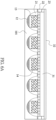
- the electrically conductive structure layer 11 of the lithium electrode 10 includes a plurality of recesses 111.
- the porous covering layer 15 serves as a separator.
- the positive active material layer 31 and the positive current collector 32 are disposed thereon sequentially.
- the electrically insulating glue frames 21 of the adjacent recesses 111 are connected, and the electrically insulating glue frames 21 in the side edges are adhered with the first adhesive layer 22 and the second adhesive layer 23 to the positive current collector 32 to form the package for the battery system.
- the materials of the first adhesive layer 22 and the second adhesive layer 23 may be the same with the material of the electrically insulating glue frames 21.
- the recess 111 is only illustrated as a blind hole, such as shown in FIG. 4B .
- the recess 111 only can be a blind hole.
- the electrically conductive structure layer 11, shown in FIG. 3A , or the combinations thereof can also be adapted. Further, the size, location, distance or the distribution of the recess 111 may be varied.
- one or more recess 111 may have a separate adhesive structure to improve adhesive.
- the separate electrically insulating glue frame 21 is also adhered with the first adhesive layer 22 and the second adhesive layer 23 to the positive current collector 32 to form the package for the battery system.
- all the electrically insulating glue frames 21 of the recesses 111 are separate, and the separate first adhesive layers 22 and the separate second adhesive layers 23 are adhered to the positive current collector 32 to extremely improve adhesive thereof.
- this invention provides a lithium electrode.
- the growth of the lithium dendrites is constrained by the solid electrolyte layer to push the solid electrolyte layer to press the electrolyte storage layer.
- the electrolyte storage layer will be deformed to squeeze out parts of the liquid and/or gel electrolyte impregnated therein.
- the resistive force to compress the electrolyte storage layer will become larger to inhibit the vertical growth of the lithium dendrites and force the lithium dendrites to grow in a horizontal direction.
- the penetration through issue for the electrical insulator, i.e. the separator, caused by the lithium dendrites can be eliminated to avoid inner shorting to greatly improve the safety of the lithium batteries.
- the solid electrolyte layer When the lithium metal is striped, the solid electrolyte layer will move back to the original position and the electrolyte storage layer will recover to the original state.
- the squeezed-out liquid and/or gel electrolyte will flow back to be impregnated in the electrolyte storage layer.
- the lithium metal layer and the liquid and/or gel electrolyte impregnated in the electrolyte storage layer are separated by the solid electrolyte layer.
- the liquid or gel electrolyte impregnated in the electrolyte storage layer does not contact to the negative active material, the lithium metal layer, to avoid the liquid or gel electrolyte being decomposed or degradation and reduce the irreversible capacity losses.
Landscapes
- Chemical & Material Sciences (AREA)
- Chemical Kinetics & Catalysis (AREA)
- Electrochemistry (AREA)
- General Chemical & Material Sciences (AREA)
- Engineering & Computer Science (AREA)
- Manufacturing & Machinery (AREA)
- Materials Engineering (AREA)
- General Physics & Mathematics (AREA)
- Condensed Matter Physics & Semiconductors (AREA)
- Inorganic Chemistry (AREA)
- Physics & Mathematics (AREA)
- Battery Electrode And Active Subsutance (AREA)
- Secondary Cells (AREA)
- Cell Electrode Carriers And Collectors (AREA)
- Cell Separators (AREA)
- Primary Cells (AREA)
Applications Claiming Priority (1)
| Application Number | Priority Date | Filing Date | Title |
|---|---|---|---|
| TW110132793A TWI762418B (zh) | 2021-09-03 | 2021-09-03 | 鋰金屬極板 |
Publications (3)
| Publication Number | Publication Date |
|---|---|
| EP4156325A1 true EP4156325A1 (de) | 2023-03-29 |
| EP4156325C0 EP4156325C0 (de) | 2025-07-30 |
| EP4156325B1 EP4156325B1 (de) | 2025-07-30 |
Family
ID=82198828
Family Applications (1)
| Application Number | Title | Priority Date | Filing Date |
|---|---|---|---|
| EP22189884.4A Active EP4156325B1 (de) | 2021-09-03 | 2022-08-11 | Lithiumelektrode |
Country Status (9)
| Country | Link |
|---|---|
| US (2) | US11862802B2 (de) |
| EP (1) | EP4156325B1 (de) |
| JP (1) | JP7174883B1 (de) |
| KR (1) | KR102473504B1 (de) |
| CN (1) | CN115763704B (de) |
| AU (1) | AU2022211786B2 (de) |
| CA (1) | CA3169657C (de) |
| MX (1) | MX2022010819A (de) |
| TW (1) | TWI762418B (de) |
Citations (3)
| Publication number | Priority date | Publication date | Assignee | Title |
|---|---|---|---|---|
| US20170294678A1 (en) * | 2016-04-11 | 2017-10-12 | Samsung Electronics Co., Ltd. | Composite solid electrolyte, protected anode and lithium battery including the same, and method of preparing the composite solid electrolyte |
| US20180102523A1 (en) * | 2016-10-12 | 2018-04-12 | Prologium Technology Co., Ltd. | Lithium metal electrode and its related lithium metal battery |
| US20200212491A1 (en) * | 2019-01-02 | 2020-07-02 | International Business Machines Corporation | Fabrication of all-solid-state energy storage devices |
Family Cites Families (20)
| Publication number | Priority date | Publication date | Assignee | Title |
|---|---|---|---|---|
| US9641902B2 (en) | 2007-06-26 | 2017-05-02 | Broadband Itv, Inc. | Dynamic adjustment of electronic program guide displays based on viewer preferences for minimizing navigation in VOD program selection |
| JP5447578B2 (ja) | 2012-04-27 | 2014-03-19 | 株式会社豊田自動織機 | 固体電解質及び二次電池 |
| KR101987008B1 (ko) | 2012-06-15 | 2019-06-12 | 한국전자통신연구원 | 고체 고분자 전해질, 그 제조방법, 및 이를 포함하는 리튬전지 |
| WO2014176266A1 (en) | 2013-04-23 | 2014-10-30 | Applied Materials, Inc. | Electrochemical cell with solid and liquid electrolytes |
| KR101621410B1 (ko) | 2013-09-11 | 2016-05-16 | 주식회사 엘지화학 | 리튬 전극 및 그를 포함하는 리튬 이차전지 |
| DE102014221261A1 (de) | 2014-10-20 | 2016-04-21 | Robert Bosch Gmbh | Separator und galvanische Zelle mit robuster Trennung von Kathode und Anode |
| US10601071B2 (en) * | 2014-12-02 | 2020-03-24 | Polyplus Battery Company | Methods of making and inspecting a web of vitreous lithium sulfide separator sheet and lithium electrode assemblies |
| US10062922B2 (en) * | 2015-01-26 | 2018-08-28 | University Of Dayton | Lithium batteries having artificial solid electrolyte interphase membrane for anode protection |
| KR102466670B1 (ko) * | 2015-05-29 | 2022-11-14 | 삼성전자주식회사 | 리튬 전지용 전해질, 및 이를 포함하는 음극 및 리튬 전지 |
| US10741846B2 (en) * | 2016-05-09 | 2020-08-11 | Samsung Electronics Co., Ltd. | Negative electrode for lithium metal battery and lithium metal battery comprising the same |
| US10665844B2 (en) | 2016-10-12 | 2020-05-26 | Prologium Technology Co., Ltd. | Lithium metal electrode and its related lithium metal battery |
| JP7117658B2 (ja) | 2017-05-29 | 2022-08-15 | パナソニックIpマネジメント株式会社 | リチウム金属二次電池 |
| JP6838521B2 (ja) | 2017-08-10 | 2021-03-03 | トヨタ自動車株式会社 | 全固体電池および負極 |
| KR20190076769A (ko) * | 2017-12-22 | 2019-07-02 | 주식회사 포스코 | 리튬 금속 음극, 이의 제조 방법 및 이를 포함하는 리튬 이차 전지 |
| US10615647B2 (en) | 2018-02-02 | 2020-04-07 | Energous Corporation | Systems and methods for detecting wireless power receivers and other objects at a near-field charging pad |
| US12300782B2 (en) * | 2018-04-06 | 2025-05-13 | Celgard, Llc | Solid state batteries, SSE batteries, lithium metal batteries with solid state electrolytes, HSSE, separators, and/or coatings, and/or related methods |
| US10930972B2 (en) * | 2019-01-25 | 2021-02-23 | Toyota Motor Engineering & Manufacturing North America, Inc. | Metal-phosphorous sulfide additives for solid state batteries |
| CN111725558B (zh) | 2019-03-20 | 2023-03-17 | 宁德时代新能源科技股份有限公司 | 一种固态电解质及其全固态锂金属电池 |
| CN112786969B (zh) | 2019-11-08 | 2023-08-29 | 辉能科技股份有限公司 | 锂电池结构及其极层结构 |
| US11444285B2 (en) * | 2020-02-28 | 2022-09-13 | Nissan North America, Inc. | Three-dimensional anode current collector for lithium batteries |
-
2021
- 2021-09-03 TW TW110132793A patent/TWI762418B/zh active
-
2022
- 2022-07-21 CN CN202210873918.1A patent/CN115763704B/zh active Active
- 2022-08-01 AU AU2022211786A patent/AU2022211786B2/en active Active
- 2022-08-03 US US17/880,122 patent/US11862802B2/en active Active
- 2022-08-05 CA CA3169657A patent/CA3169657C/en active Active
- 2022-08-11 EP EP22189884.4A patent/EP4156325B1/de active Active
- 2022-08-19 KR KR1020220104102A patent/KR102473504B1/ko active Active
- 2022-08-30 JP JP2022136850A patent/JP7174883B1/ja active Active
- 2022-08-31 MX MX2022010819A patent/MX2022010819A/es unknown
-
2023
- 2023-11-20 US US18/514,381 patent/US20240088400A1/en not_active Abandoned
Patent Citations (3)
| Publication number | Priority date | Publication date | Assignee | Title |
|---|---|---|---|---|
| US20170294678A1 (en) * | 2016-04-11 | 2017-10-12 | Samsung Electronics Co., Ltd. | Composite solid electrolyte, protected anode and lithium battery including the same, and method of preparing the composite solid electrolyte |
| US20180102523A1 (en) * | 2016-10-12 | 2018-04-12 | Prologium Technology Co., Ltd. | Lithium metal electrode and its related lithium metal battery |
| US20200212491A1 (en) * | 2019-01-02 | 2020-07-02 | International Business Machines Corporation | Fabrication of all-solid-state energy storage devices |
Also Published As
| Publication number | Publication date |
|---|---|
| MX2022010819A (es) | 2023-03-06 |
| US11862802B2 (en) | 2024-01-02 |
| CN115763704A (zh) | 2023-03-07 |
| TWI762418B (zh) | 2022-04-21 |
| AU2022211786B2 (en) | 2024-02-01 |
| CN115763704B (zh) | 2024-11-26 |
| KR102473504B1 (ko) | 2022-12-01 |
| US20240088400A1 (en) | 2024-03-14 |
| TW202312534A (zh) | 2023-03-16 |
| JP2023037600A (ja) | 2023-03-15 |
| AU2022211786A1 (en) | 2023-03-23 |
| JP7174883B1 (ja) | 2022-11-17 |
| BR102022015974A2 (pt) | 2023-03-14 |
| CA3169657A1 (en) | 2023-03-03 |
| CA3169657C (en) | 2024-04-09 |
| EP4156325C0 (de) | 2025-07-30 |
| EP4156325B1 (de) | 2025-07-30 |
| US20230073409A1 (en) | 2023-03-09 |
Similar Documents
| Publication | Publication Date | Title |
|---|---|---|
| US5387482A (en) | Multilayered electrolyte and electrochemical cells used same | |
| US10581111B2 (en) | Ceramic lithium retention device | |
| US11699830B2 (en) | Spacers for providing protection of electrochemical battery enclosures and systems and methods therefor | |
| CN101501903A (zh) | 电化学能量源、电子设备和制造这种电化学能量源的方法 | |
| US20130157152A1 (en) | Metal-air battery with dual electrode anode | |
| EP3819960B1 (de) | Lithiumbatteriestruktur und elektrodenschicht dafür | |
| US12272796B2 (en) | Lithium battery structure and electrode layer thereof | |
| KR20160086195A (ko) | 전극, 이의 제조방법, 이에 의해 제조된 전극 및 이를 포함하는 이차전지 | |
| EP4156325A1 (de) | Lithiumelektrode | |
| Iwakura et al. | Charge-discharge and capacity retention characteristics of new type Ni/MH batteries using polymer hydrogel electrolyte | |
| RU2792972C1 (ru) | Литиевый электрод | |
| WO2021106481A1 (ja) | 電池 | |
| EP3748755A1 (de) | Zellbatterie | |
| KR101101546B1 (ko) | 전기 화학 커패시터 및 이의 제조방법 | |
| BR102022015974B1 (pt) | Eletrodo de lítio | |
| CN114026722B (zh) | 隔板、包含该隔板的电化学装置及电子装置 | |
| US20250132376A1 (en) | Lithium-ion secondary battery and negative electrode structure | |
| KR100502320B1 (ko) | 리튬 이온 폴리머 전지 | |
| KR20240022277A (ko) | 이차 전지용 음극 및 이를 포함하는 이차 전지 | |
| KR20250168009A (ko) | 전지 셀 장착 장치, 이를 포함하는 전지 팩 및 전지 셀 장착 장치 제조 방법 | |
| CN121076060A (zh) | 电极板、包括电极板的二次电池和制造二次电池的方法 |
Legal Events
| Date | Code | Title | Description |
|---|---|---|---|
| PUAI | Public reference made under article 153(3) epc to a published international application that has entered the european phase |
Free format text: ORIGINAL CODE: 0009012 |
|
| STAA | Information on the status of an ep patent application or granted ep patent |
Free format text: STATUS: THE APPLICATION HAS BEEN PUBLISHED |
|
| AK | Designated contracting states |
Kind code of ref document: A1 Designated state(s): AL AT BE BG CH CY CZ DE DK EE ES FI FR GB GR HR HU IE IS IT LI LT LU LV MC MK MT NL NO PL PT RO RS SE SI SK SM TR |
|
| STAA | Information on the status of an ep patent application or granted ep patent |
Free format text: STATUS: REQUEST FOR EXAMINATION WAS MADE |
|
| 17P | Request for examination filed |
Effective date: 20230927 |
|
| RBV | Designated contracting states (corrected) |
Designated state(s): AL AT BE BG CH CY CZ DE DK EE ES FI FR GB GR HR HU IE IS IT LI LT LU LV MC MK MT NL NO PL PT RO RS SE SI SK SM TR |
|
| GRAP | Despatch of communication of intention to grant a patent |
Free format text: ORIGINAL CODE: EPIDOSNIGR1 |
|
| STAA | Information on the status of an ep patent application or granted ep patent |
Free format text: STATUS: GRANT OF PATENT IS INTENDED |
|
| INTG | Intention to grant announced |
Effective date: 20250321 |
|
| GRAS | Grant fee paid |
Free format text: ORIGINAL CODE: EPIDOSNIGR3 |
|
| GRAA | (expected) grant |
Free format text: ORIGINAL CODE: 0009210 |
|
| STAA | Information on the status of an ep patent application or granted ep patent |
Free format text: STATUS: THE PATENT HAS BEEN GRANTED |
|
| AK | Designated contracting states |
Kind code of ref document: B1 Designated state(s): AL AT BE BG CH CY CZ DE DK EE ES FI FR GB GR HR HU IE IS IT LI LT LU LV MC MK MT NL NO PL PT RO RS SE SI SK SM TR |
|
| REG | Reference to a national code |
Ref country code: GB Ref legal event code: FG4D |
|
| REG | Reference to a national code |
Ref country code: CH Ref legal event code: EP |
|
| REG | Reference to a national code |
Ref country code: DE Ref legal event code: R096 Ref document number: 602022018346 Country of ref document: DE |
|
| REG | Reference to a national code |
Ref country code: IE Ref legal event code: FG4D |
|
| U01 | Request for unitary effect filed |
Effective date: 20250821 |
|
| U07 | Unitary effect registered |
Designated state(s): AT BE BG DE DK EE FI FR IT LT LU LV MT NL PT RO SE SI Effective date: 20250829 |
|
| U20 | Renewal fee for the european patent with unitary effect paid |
Year of fee payment: 4 Effective date: 20250930 |
|
| PG25 | Lapsed in a contracting state [announced via postgrant information from national office to epo] |
Ref country code: IS Free format text: LAPSE BECAUSE OF FAILURE TO SUBMIT A TRANSLATION OF THE DESCRIPTION OR TO PAY THE FEE WITHIN THE PRESCRIBED TIME-LIMIT Effective date: 20251130 |
|
| PG25 | Lapsed in a contracting state [announced via postgrant information from national office to epo] |
Ref country code: NO Free format text: LAPSE BECAUSE OF FAILURE TO SUBMIT A TRANSLATION OF THE DESCRIPTION OR TO PAY THE FEE WITHIN THE PRESCRIBED TIME-LIMIT Effective date: 20251030 |
|
| PG25 | Lapsed in a contracting state [announced via postgrant information from national office to epo] |
Ref country code: HR Free format text: LAPSE BECAUSE OF FAILURE TO SUBMIT A TRANSLATION OF THE DESCRIPTION OR TO PAY THE FEE WITHIN THE PRESCRIBED TIME-LIMIT Effective date: 20250730 |
|
| PG25 | Lapsed in a contracting state [announced via postgrant information from national office to epo] |
Ref country code: GR Free format text: LAPSE BECAUSE OF FAILURE TO SUBMIT A TRANSLATION OF THE DESCRIPTION OR TO PAY THE FEE WITHIN THE PRESCRIBED TIME-LIMIT Effective date: 20251031 |
|
| PG25 | Lapsed in a contracting state [announced via postgrant information from national office to epo] |
Ref country code: PL Free format text: LAPSE BECAUSE OF FAILURE TO SUBMIT A TRANSLATION OF THE DESCRIPTION OR TO PAY THE FEE WITHIN THE PRESCRIBED TIME-LIMIT Effective date: 20250730 |
|
| PG25 | Lapsed in a contracting state [announced via postgrant information from national office to epo] |
Ref country code: RS Free format text: LAPSE BECAUSE OF FAILURE TO SUBMIT A TRANSLATION OF THE DESCRIPTION OR TO PAY THE FEE WITHIN THE PRESCRIBED TIME-LIMIT Effective date: 20251030 |
|
| PG25 | Lapsed in a contracting state [announced via postgrant information from national office to epo] |
Ref country code: ES Free format text: LAPSE BECAUSE OF FAILURE TO SUBMIT A TRANSLATION OF THE DESCRIPTION OR TO PAY THE FEE WITHIN THE PRESCRIBED TIME-LIMIT Effective date: 20250730 |