EP4155567B1 - Anschlagring für die kugeln eines kugelgleichlaufgelenks mit einem dichtungsbalg - Google Patents
Anschlagring für die kugeln eines kugelgleichlaufgelenks mit einem dichtungsbalg Download PDFInfo
- Publication number
- EP4155567B1 EP4155567B1 EP22197045.2A EP22197045A EP4155567B1 EP 4155567 B1 EP4155567 B1 EP 4155567B1 EP 22197045 A EP22197045 A EP 22197045A EP 4155567 B1 EP4155567 B1 EP 4155567B1
- Authority
- EP
- European Patent Office
- Prior art keywords
- retaining ring
- bellows
- ring
- retaining
- transmission joint
- Prior art date
- Legal status (The legal status is an assumption and is not a legal conclusion. Google has not performed a legal analysis and makes no representation as to the accuracy of the status listed.)
- Active
Links
Images

Classifications
-
- F—MECHANICAL ENGINEERING; LIGHTING; HEATING; WEAPONS; BLASTING
- F16—ENGINEERING ELEMENTS AND UNITS; GENERAL MEASURES FOR PRODUCING AND MAINTAINING EFFECTIVE FUNCTIONING OF MACHINES OR INSTALLATIONS; THERMAL INSULATION IN GENERAL
- F16D—COUPLINGS FOR TRANSMITTING ROTATION; CLUTCHES; BRAKES
- F16D3/00—Yielding couplings, i.e. with means permitting movement between the connected parts during the drive
- F16D3/84—Shrouds, e.g. casings, covers; Sealing means specially adapted therefor
- F16D3/843—Shrouds, e.g. casings, covers; Sealing means specially adapted therefor enclosed covers
- F16D3/845—Shrouds, e.g. casings, covers; Sealing means specially adapted therefor enclosed covers allowing relative movement of joint parts due to the flexing of the cover
-
- F—MECHANICAL ENGINEERING; LIGHTING; HEATING; WEAPONS; BLASTING
- F16—ENGINEERING ELEMENTS AND UNITS; GENERAL MEASURES FOR PRODUCING AND MAINTAINING EFFECTIVE FUNCTIONING OF MACHINES OR INSTALLATIONS; THERMAL INSULATION IN GENERAL
- F16D—COUPLINGS FOR TRANSMITTING ROTATION; CLUTCHES; BRAKES
- F16D3/00—Yielding couplings, i.e. with means permitting movement between the connected parts during the drive
- F16D3/16—Universal joints in which flexibility is produced by means of pivots or sliding or rolling connecting parts
- F16D3/20—Universal joints in which flexibility is produced by means of pivots or sliding or rolling connecting parts one coupling part entering a sleeve of the other coupling part and connected thereto by sliding or rolling members
- F16D3/22—Universal joints in which flexibility is produced by means of pivots or sliding or rolling connecting parts one coupling part entering a sleeve of the other coupling part and connected thereto by sliding or rolling members the rolling members being balls, rollers, or the like, guided in grooves or sockets in both coupling parts
- F16D3/223—Universal joints in which flexibility is produced by means of pivots or sliding or rolling connecting parts one coupling part entering a sleeve of the other coupling part and connected thereto by sliding or rolling members the rolling members being balls, rollers, or the like, guided in grooves or sockets in both coupling parts the rolling members being guided in grooves in both coupling parts
- F16D2003/22316—Means for fastening or attaching the bellows or gaiters
-
- F—MECHANICAL ENGINEERING; LIGHTING; HEATING; WEAPONS; BLASTING
- F16—ENGINEERING ELEMENTS AND UNITS; GENERAL MEASURES FOR PRODUCING AND MAINTAINING EFFECTIVE FUNCTIONING OF MACHINES OR INSTALLATIONS; THERMAL INSULATION IN GENERAL
- F16D—COUPLINGS FOR TRANSMITTING ROTATION; CLUTCHES; BRAKES
- F16D3/00—Yielding couplings, i.e. with means permitting movement between the connected parts during the drive
- F16D3/16—Universal joints in which flexibility is produced by means of pivots or sliding or rolling connecting parts
- F16D3/20—Universal joints in which flexibility is produced by means of pivots or sliding or rolling connecting parts one coupling part entering a sleeve of the other coupling part and connected thereto by sliding or rolling members
- F16D3/22—Universal joints in which flexibility is produced by means of pivots or sliding or rolling connecting parts one coupling part entering a sleeve of the other coupling part and connected thereto by sliding or rolling members the rolling members being balls, rollers, or the like, guided in grooves or sockets in both coupling parts
- F16D3/223—Universal joints in which flexibility is produced by means of pivots or sliding or rolling connecting parts one coupling part entering a sleeve of the other coupling part and connected thereto by sliding or rolling members the rolling members being balls, rollers, or the like, guided in grooves or sockets in both coupling parts the rolling members being guided in grooves in both coupling parts
- F16D3/226—Universal joints in which flexibility is produced by means of pivots or sliding or rolling connecting parts one coupling part entering a sleeve of the other coupling part and connected thereto by sliding or rolling members the rolling members being balls, rollers, or the like, guided in grooves or sockets in both coupling parts the rolling members being guided in grooves in both coupling parts the groove centre-lines in each coupling part lying on a cylinder co-axial with the respective coupling part
- F16D3/227—Universal joints in which flexibility is produced by means of pivots or sliding or rolling connecting parts one coupling part entering a sleeve of the other coupling part and connected thereto by sliding or rolling members the rolling members being balls, rollers, or the like, guided in grooves or sockets in both coupling parts the rolling members being guided in grooves in both coupling parts the groove centre-lines in each coupling part lying on a cylinder co-axial with the respective coupling part the joints being telescopic
Definitions
- the field of the invention is that of transmission joints, in particular transmission joints.
- the invention relates to a ball retaining ring of a transmission joint adapted to be mounted on one end of a protective bellows of the transmission joint.
- the invention finds applications in particular in the automotive field, in particular in the transmission of the drive wheels of a motor vehicle, and more generally in the context of the transmission of movement and force between shafts forming an angle between them.
- Ball joints are generally used for the transmission of rotation between two shafts forming an angle, which is often variable.
- Ball joint transmissions generally consist of a part called a bowl, in which is arranged a part called a nut, the nut having grooves accommodating the balls of the transmission joint.
- the balls are simply inserted into the grooves of the nut.
- the shafts form a significant angle of one degree, the balls are brought into extreme positions in the grooves, which can result in the ball coming out of the transmission joint.
- none of the current systems can simultaneously meet all the required needs, namely to propose a technique for preventing one or more balls from coming out of the groove of the transmission joint, which is simple and inexpensive to implement, while not requiring any additional step during the assembly of the transmission joint.
- the present invention aims to remedy all or part of the drawbacks of the state of the art cited above.
- the retention ring is delivered pre-arranged on a protective bellows, the operator in charge of assembly only having to fix the two pre-assembled elements on top of each other simultaneously, thus not adding any additional fixing step for the end user of the product.
- the retention ring allows a dual function of holding the bellows on the seal, and retaining balls in the seal, while requiring no additional parts or elements compared to a conventional retaining ring.
- the ring according to the invention alone allows ball retention.
- the retention collar has an internal surface portion at which the diameter of the collar decreases the further one moves axially from a bowl of the transmission joint, when the ring is mounted on said bellows.
- the retention collar has an internal surface portion of substantially truncated cone shape, the substantially truncated cone shape being open towards said balls of the transmission joint when the ring is mounted on said bellows.
- substantially truncated cone shape is meant a shape inscribed between two concentric truncated cones, with diameters of the same order of magnitude.
- the balls face a generally frustoconical surface which prevents them from escaping axially, the diameter at the level of the frustoconical surface decreasing the further one moves axially from the bowl of the transmission joint, that is to say from the nominal location of the balls.
- the retention collar is linked to the annular portion by a side of greater diameter, so as to form a retention ring of constant diameter, then decreasing, in the direction going from the annular portion towards the retention collar.
- the retention ring comprises two clearly defined zones, a zone of constant diameter used for positioning and fixing the ring on the bellows and the bowl of the transmission joint, and a zone providing a retention stop.
- the connection between the collar and the annular portion is a material connection, although it is possible to connect the two parts by gluing, clipping, screwing, etc.
- the deformable annular portion consists of a tubular wall comprising at least one through slot made in an axial direction of the ring, so as to reduce the rigidity of said annular portion.
- the slot is not through, but forms a groove substantially reducing the rigidity of the annular portion.
- any other solution to reduce the rigidity of the annular portion is also possible, such as the presence of other slots, arranged differently, or the use of a more flexible material, capable of elastic deformation. In the latter case, it is possible to make the retention ring in two parts of different material, the parts being subsequently linked by a suitable means.
- the tubular wall comprises four through slots distributed regularly on said tubular wall.
- the deformable annular portion comprises, on its outer surface, means for positioning, or axial pre-positioning of the clamping collar on said retaining ring.
- the axial positioning of the clamping collar is carried out effortlessly by the operator responsible for assembly, and furthermore, axial displacement of the clamped collar can be avoided, thereby preventing the protective bellows from becoming detached and the transmission joint from deteriorating.
- the means for axially positioning the clamping collar on the retention ring are constituted by an annular groove, and/or two series of positioning ears projecting radially from said annular portion and delimiting an annular zone for receiving the clamping collar.
- the retaining ring and the bellows are packaged together, the installation of the bellows by the operator responsible for mounting the bellows and the retaining ring on the transmission joint is accelerated. Indeed, the operator will not have to make any effort to find the correct positioning of the retaining ring, the latter being already positioned on the end of the protective bellows, and cannot slide further onto the bellows. Thus, the retaining ring is already precisely positioned when the operator takes hold of it for assembly.
- the invention is implemented according to the embodiments and variants set out below, which are to be considered individually or in any technically effective combination.
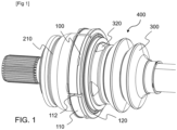
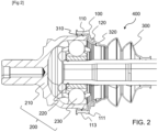
- a transmission assembly 400 comprises a transmission joint 200 between two shafts, a first shaft being secured to a bowl 210 of the transmission joint 200, and a second shaft being secured to a nut 220 of the transmission joint 200.
- the bowl 210 and the nut 220 comprise rails or grooves in which balls 230 are arranged.
- the balls 230 thus allow a bent position of the shafts, but do not leave any degree of freedom in rotation around the axes of the shafts. In this way, a rotational movement, and a torque can be transmitted by the transmission joint 200.
- a family of this type of transmission joints is known as "Rzeppa joint", from the name of their inventor.
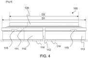
- the retaining ring 100 comprises a deformable annular portion 110, of diameter D1, adapted to receive a clamping collar of the bellows 300 on the transmission joint 200.
- the retention ring 100 also comprises a retention collar 120 extending towards the inside of the retention ring 100, so as to form a retention stop for the balls 230 of the transmission joint 200, aimed at preventing the axial exit of the balls 230 from the transmission joint 200.
- the retention collar 120 has an internal surface portion of generally truncated cone shape, open in the direction of the balls 230 of the transmission joint 200 when the ring is mounted on the bellows 300.
- the balls 230 face a truncated surface which prevents them from escaping axially, the diameter at the level of the truncated surface decreasing the further one moves axially away from the bowl 210.
- the retention collar 120 has a side with an upper diameter D1, corresponding to the diameter D1 of the annular portion, and a side with a lower diameter D2, which is less than the upper diameter D1.
- the lower diameter D2 of the collar 120 is necessary for the lower diameter D2 of the collar 120 to be less than the internal diameter of the bowl 210, that is to say less than the diameter of the circle to which the bottoms of the rails or grooves of the bowl 210 are tangent.
- the retention collar 120 is linked to the annular portion 110 by the side of greater diameter D1, so as to form a retention ring 100 of diameter D1, then decreasing towards the lower diameter D2, in the direction going from the annular portion 110 towards the retention collar 120.
- connection is a material connection, that is to say that the retention ring 100 is made from a single piece, although a two-part construction is possible (and the two parts are then connected together).
- the material constituting the retention ring 100 may be a plastic material, such as for example polyamide, which may be loaded with a reinforcing material, such as fiberglass.
- the retention ring 100 is produced in a single step, by molding for example, at lower cost.
- the deformable annular portion 110 consists of a tubular wall 111 comprising at least one slot 112, made in an axial direction of the retention ring 100, so as to reduce the rigidity of the annular portion 110.
- the tubular wall 111 comprises four through slots 112 distributed regularly over the tubular wall 111, although it is possible to have a smaller or larger number of them.
- the presence of four through slots 112 guarantees good flexibility of the annular portion 110 while avoiding making it too fragile.
- the deformable annular portion 110 comprises, on its outer surface, means for axially positioning the clamping collar on the retaining ring 100.
- positioning means acting as stops can be chosen.
- Such means for axial positioning of the clamping collar are for example constituted by an annular groove 113 made in the tubular wall 111, on its outer side. It is understood that the width of the groove 113 is at least equal to the width of the clamping collar, so that the edges of the groove 113 delimit a positioning zone of the clamping collar, forming a stop with the latter.
- Such axial positioning means for the clamping collar are also constituted (in isolation or in combination with the groove 113) by one or two series of positioning lugs projecting radially from the annular portion 110, so as to form a stop with the clamping collar.
- the clamping collar is positioned axially in only one direction, whereas when there are two series 114 and 115, the series delimit an annular zone for receiving the clamping collar.
- the ears of the series of positioning ears 114 and 115 are flush with the edge of the groove 113, when these two positioning means are implemented jointly.
- the positioning area of the clamping collar defined by the groove 113 corresponds in this case to the annular receiving area of the clamping collar defined between the series of positioning ears 114 and 115, resulting in a greater height stop at the positioning ears, and thus in a more secure axial positioning of the clamping collar.
- the retaining ring 100 fulfills its role of retaining the balls 230 by being fixed to the outside of the bowl 210 by its annular portion 110, the balls being retained by the retaining collar 120.
- the annular portion 110 is itself fixed to the bowl 210 but also serves as an intermediate fixing for the protective bellows 300.
- the retaining collar 120 retains the balls 230, thus forming a retention stop.
- the protective bellows 300 is adapted to accommodate the retention ring 100, in particular with regard to its axial positioning on the protective bellows 300.
- the protective bellows 300 comprises an axial positioning stop for the ring 100 in the form of at least two lugs 320 for axial positioning of the retaining ring 100, the positioning lugs 320 forming an axial stop with the retaining collar 120.
- the lugs 320 can take any shape capable of forming an axial stop, the shape shown in particular in FIG. Figure 1 not being limiting.
- the retaining ring 100 is thus held on the end 310 without risk of sliding further onto the bellows 300.
Landscapes
- Engineering & Computer Science (AREA)
- General Engineering & Computer Science (AREA)
- Mechanical Engineering (AREA)
- Diaphragms And Bellows (AREA)
- Pivots And Pivotal Connections (AREA)
- Snaps, Bayonet Connections, Set Pins, And Snap Rings (AREA)
Claims (11)
- Rückhaltering (100) von Kugeln (230) einer Kugelübertragungsverbindung (200), der geeignet ist, an einem Ende (310) eines Schutzbalgs (300) der Übertragungsverbindung montiert zu werden, dadurch gekennzeichnet, dass der Rückhaltering Folgendes aufweist:• einen verformbaren Ringabschnitt (110) mit konstantem Durchmesser, der geeignet ist, einen Spannring des Balgs an der Übertragungsverbindung aufzunehmen, und• eine Rückhaltemanschette (120), die sich zum Inneren des Rückhalterings erstreckt, um einen Rückhalteanschlag für die Kugeln der Übertragungsverbindung zu bilden, der das axiale Heraustreten der Kugeln aus der Übertragungsverbindung verhindert.
- Rückhaltering (100) nach Anspruch 1, wobei die Rückhaltemanschette (120) einen inneren Oberflächenabschnitt aufweist, an dem der Durchmesser der Manschette abnimmt, je weiter man sich axial von einer Trommel (210) der Übertragungsverbindung (200) entfernt, wenn der Ring auf dem Balg (300) montiert ist.
- Rückhaltering (100) nach einem der Ansprüche 1 oder 2, wobei der verformbare Ringabschnitt (110) eine röhrenförmige Wand (111) mit mindestens einem durchgehenden Schlitz (112) aufweist, der in einer axialen Richtung des Rings ausgebildet wird, um die Steifigkeit des Ringabschnitts zu verringern.
- Rückhaltering (100) nach Anspruch 3, wobei die Rohrwand (111) vier gleichmäßig über die Rohrwand verteilte durchgehende Schlitze (112) aufweist.
- Rückhaltering (100) nach einem der Ansprüche 1 bis 4, wobei der verformbare Ringabschnitt (110) an seiner Außenfläche axiale Positionierungsmittel (113, 114, 115) des Spannrings auf dem Rückhaltering aufweist.
- Rückhaltering (100) nach Anspruch 5, wobei die Mittel zur axialen Positionierung des Spannrings auf dem Rückhaltering aus einer ringförmigen Nut (113) und/oder zwei Reihen (114, 115) von Positionierungsnasen bestehen, die radial aus dem Ringabschnitt (110) hervorstehen und einen ringförmigen Aufnahmebereich des Spannrings begrenzen.
- Rückhaltering (100) nach einem der Ansprüche 1 bis 6, wobei der Rückhaltering aus einem Stück hergestellt ist.
- Rückhaltering (100) nach einem der Ansprüche 1 bis 7, wobei der Rückhaltering aus Kunststoffmaterial und vorzugsweise aus Polyamid, vorzugsweise mit Glasfaser gefüllt, besteht.
- Schutzbalg (300) einer Übertragungsverbindung, der einen Rückhaltering (100) nach einem der Ansprüche 1 bis 8 aufweist, wobei der Rückhaltering an einem Ende (310) des Schutzbalgs angeordnet ist.
- Balg (300) nach Anspruch 9, der einen axialen Positionierungsanschlag des Rückhalterings (100) in Form eines Rings oder mindestens zwei Positionierungsösen (320) aufweist, wobei der axiale Positionierungsanschlag einen axialen Anschlag mit der Rückhaltemanschette (120) bildet.
- Übertragungseinheit (400) umfassend eine Kugelübertragungsverbindung (200), die eine Trommel (210) aufweist, an der ein Schutzbalg (300) mit einem Rückhaltering (100) nach einem der Ansprüche 1 bis 8 befestigt ist, wobei der Balg und der Rückhaltering mittels eines Spannrings an der Trommel befestigt sind.
Applications Claiming Priority (1)
| Application Number | Priority Date | Filing Date | Title |
|---|---|---|---|
| FR2110029A FR3127267B1 (fr) | 2021-09-23 | 2021-09-23 | Bague de rétention de billes d’un joint de transmission |
Publications (3)
| Publication Number | Publication Date |
|---|---|
| EP4155567A1 EP4155567A1 (de) | 2023-03-29 |
| EP4155567B1 true EP4155567B1 (de) | 2025-06-25 |
| EP4155567C0 EP4155567C0 (de) | 2025-06-25 |
Family
ID=78820606
Family Applications (1)
| Application Number | Title | Priority Date | Filing Date |
|---|---|---|---|
| EP22197045.2A Active EP4155567B1 (de) | 2021-09-23 | 2022-09-22 | Anschlagring für die kugeln eines kugelgleichlaufgelenks mit einem dichtungsbalg |
Country Status (4)
| Country | Link |
|---|---|
| EP (1) | EP4155567B1 (de) |
| ES (1) | ES3039149T3 (de) |
| FR (1) | FR3127267B1 (de) |
| PL (1) | PL4155567T3 (de) |
Family Cites Families (7)
| Publication number | Priority date | Publication date | Assignee | Title |
|---|---|---|---|---|
| DE2927648A1 (de) * | 1979-07-09 | 1981-01-29 | Leopold F Schmid | Drehgelenkkupplung, insbesondere zum antrieb der raeder eines kraftfahrzeuges |
| DE3820449A1 (de) * | 1988-06-16 | 1989-12-21 | Loehr & Bromkamp Gmbh | Gleichlaufverschiebegelenk mit anschlaegen |
| JP5073319B2 (ja) * | 2007-03-02 | 2012-11-14 | 株式会社フコク | 等速ジョイント用ブーツ |
| WO2009075603A1 (fr) * | 2007-12-10 | 2009-06-18 | Evgeniji Nikolaevich Pavlov | Arbre de transmission pour moyen de transport |
| KR20130104407A (ko) * | 2012-03-14 | 2013-09-25 | 한국델파이주식회사 | 트라이포드 등속 조인트 |
| KR20130135524A (ko) * | 2012-06-01 | 2013-12-11 | 현대자동차주식회사 | 아우터레이스와 부트의 체결구조 |
| DE202013009221U1 (de) * | 2013-10-18 | 2013-11-15 | Gkn Driveline International Gmbh | Dichtbalg mit Kugelanschlag und Gleichlaufdrehgelenk mit einem solchen Dichtbalg |
-
2021
- 2021-09-23 FR FR2110029A patent/FR3127267B1/fr active Active
-
2022
- 2022-09-22 ES ES22197045T patent/ES3039149T3/es active Active
- 2022-09-22 PL PL22197045.2T patent/PL4155567T3/pl unknown
- 2022-09-22 EP EP22197045.2A patent/EP4155567B1/de active Active
Also Published As
| Publication number | Publication date |
|---|---|
| ES3039149T3 (en) | 2025-10-17 |
| EP4155567A1 (de) | 2023-03-29 |
| EP4155567C0 (de) | 2025-06-25 |
| FR3127267B1 (fr) | 2024-01-12 |
| FR3127267A1 (fr) | 2023-03-24 |
| PL4155567T3 (pl) | 2025-11-12 |
Similar Documents
| Publication | Publication Date | Title |
|---|---|---|
| EP1921362B1 (de) | Doppelspannschelle und Montageverfahren | |
| FR2901858A1 (fr) | Support pour tube ondule | |
| FR2890715A1 (fr) | Palier a douille elastomere et procede de fabrication. | |
| EP1865206A2 (de) | Keilriementriebwerk | |
| FR2706960A1 (en) | Friction clutch | |
| EP2207988B1 (de) | Vorrichtung für eine griffrosette, griffrosette und entsprechender röhrenkonnektor | |
| FR2561333A1 (fr) | Couvercle tulipe pour joint homocinetique tripode, et joint le comportant | |
| EP4155567B1 (de) | Anschlagring für die kugeln eines kugelgleichlaufgelenks mit einem dichtungsbalg | |
| FR3078759A1 (fr) | Dispositif de poulie pour galet tendeur ou enrouleur | |
| EP0794347A1 (de) | Schutzfaltenbalg für einen Antrieb | |
| EP0904499B1 (de) | Elastisches gelenk und dessen herstellungsverfahren | |
| EP1707843A1 (de) | Zweimassenschwungrad für ein Kraftfahrzeug | |
| FR2779787A1 (fr) | Bague de tolerance pour roulement | |
| EP3404278B1 (de) | Vorrichtung zur korrektur von fehlausrichtungen zwischen der kurbelwelle und der eingangswelle des getriebes, und reibungsscheibe, die mit einer solchen vorrichtung ausgestattet ist | |
| FR2850147A1 (fr) | Support anti-vibratoire. | |
| FR2613802A1 (fr) | Amortisseur de torsion, notamment disque de friction d'embrayage pour vehicule automobile | |
| EP0805090A1 (de) | Haltevorrichtung einer drehenden Welle einer Kraftfahrzeug-Lenksäule | |
| FR2717232A1 (fr) | Disque d'embrayage pour un embrayage à friction dans un véhicule automobile. | |
| WO1997036119A1 (fr) | Montage de butee de debrayage | |
| FR2503297A1 (fr) | Butee de debrayage, notamment pour vehicules automobiles | |
| EP2783129B1 (de) | Drehungsunterdrückungsvorrichtung für eine kupplung, insbesondere eines kraftfahrzeuges | |
| WO2021052941A1 (fr) | Poulie de decouplage a entrainement ameliore | |
| EP4076818A1 (de) | Anordnung aus zwei ineinander gesteckten konzentrischen teilen und verfahren zum zusammenbau dieser beiden konzentrischen teile | |
| FR2747441A1 (fr) | Montage de butee de debrayage | |
| EP0987449A1 (de) | Anordnung zur Befestigung zweier Strukturelemente eines Kraftfahrzeuges |
Legal Events
| Date | Code | Title | Description |
|---|---|---|---|
| PUAI | Public reference made under article 153(3) epc to a published international application that has entered the european phase |
Free format text: ORIGINAL CODE: 0009012 |
|
| STAA | Information on the status of an ep patent application or granted ep patent |
Free format text: STATUS: THE APPLICATION HAS BEEN PUBLISHED |
|
| AK | Designated contracting states |
Kind code of ref document: A1 Designated state(s): AL AT BE BG CH CY CZ DE DK EE ES FI FR GB GR HR HU IE IS IT LI LT LU LV MC MK MT NL NO PL PT RO RS SE SI SK SM TR |
|
| STAA | Information on the status of an ep patent application or granted ep patent |
Free format text: STATUS: REQUEST FOR EXAMINATION WAS MADE |
|
| 17P | Request for examination filed |
Effective date: 20230929 |
|
| RBV | Designated contracting states (corrected) |
Designated state(s): AL AT BE BG CH CY CZ DE DK EE ES FI FR GB GR HR HU IE IS IT LI LT LU LV MC MK MT NL NO PL PT RO RS SE SI SK SM TR |
|
| GRAP | Despatch of communication of intention to grant a patent |
Free format text: ORIGINAL CODE: EPIDOSNIGR1 |
|
| STAA | Information on the status of an ep patent application or granted ep patent |
Free format text: STATUS: GRANT OF PATENT IS INTENDED |
|
| INTG | Intention to grant announced |
Effective date: 20250312 |
|
| GRAS | Grant fee paid |
Free format text: ORIGINAL CODE: EPIDOSNIGR3 |
|
| GRAA | (expected) grant |
Free format text: ORIGINAL CODE: 0009210 |
|
| STAA | Information on the status of an ep patent application or granted ep patent |
Free format text: STATUS: THE PATENT HAS BEEN GRANTED |
|
| AK | Designated contracting states |
Kind code of ref document: B1 Designated state(s): AL AT BE BG CH CY CZ DE DK EE ES FI FR GB GR HR HU IE IS IT LI LT LU LV MC MK MT NL NO PL PT RO RS SE SI SK SM TR |
|
| REG | Reference to a national code |
Ref country code: GB Ref legal event code: FG4D Free format text: NOT ENGLISH |
|
| REG | Reference to a national code |
Ref country code: CH Ref legal event code: EP |
|
| REG | Reference to a national code |
Ref country code: DE Ref legal event code: R096 Ref document number: 602022016363 Country of ref document: DE |
|
| REG | Reference to a national code |
Ref country code: CH Ref legal event code: EP |
|
| REG | Reference to a national code |
Ref country code: IE Ref legal event code: FG4D Free format text: LANGUAGE OF EP DOCUMENT: FRENCH |
|
| U01 | Request for unitary effect filed |
Effective date: 20250722 |
|
| U07 | Unitary effect registered |
Designated state(s): AT BE BG DE DK EE FI FR IT LT LU LV MT NL PT RO SE SI Effective date: 20250728 |
|
| PG25 | Lapsed in a contracting state [announced via postgrant information from national office to epo] |
Ref country code: NO Free format text: LAPSE BECAUSE OF FAILURE TO SUBMIT A TRANSLATION OF THE DESCRIPTION OR TO PAY THE FEE WITHIN THE PRESCRIBED TIME-LIMIT Effective date: 20250925 Ref country code: GR Free format text: LAPSE BECAUSE OF FAILURE TO SUBMIT A TRANSLATION OF THE DESCRIPTION OR TO PAY THE FEE WITHIN THE PRESCRIBED TIME-LIMIT Effective date: 20250926 |
|
| PG25 | Lapsed in a contracting state [announced via postgrant information from national office to epo] |
Ref country code: HR Free format text: LAPSE BECAUSE OF FAILURE TO SUBMIT A TRANSLATION OF THE DESCRIPTION OR TO PAY THE FEE WITHIN THE PRESCRIBED TIME-LIMIT Effective date: 20250625 |
|
| REG | Reference to a national code |
Ref country code: ES Ref legal event code: FG2A Ref document number: 3039149 Country of ref document: ES Kind code of ref document: T3 Effective date: 20251017 |
|
| PG25 | Lapsed in a contracting state [announced via postgrant information from national office to epo] |
Ref country code: RS Free format text: LAPSE BECAUSE OF FAILURE TO SUBMIT A TRANSLATION OF THE DESCRIPTION OR TO PAY THE FEE WITHIN THE PRESCRIBED TIME-LIMIT Effective date: 20250925 |
|
| U20 | Renewal fee for the european patent with unitary effect paid |
Year of fee payment: 4 Effective date: 20250929 |
|
| U1N | Appointed representative for the unitary patent procedure changed after the registration of the unitary effect |
Representative=s name: SANTARELLI; FR |
|
| PG25 | Lapsed in a contracting state [announced via postgrant information from national office to epo] |
Ref country code: IS Free format text: LAPSE BECAUSE OF FAILURE TO SUBMIT A TRANSLATION OF THE DESCRIPTION OR TO PAY THE FEE WITHIN THE PRESCRIBED TIME-LIMIT Effective date: 20251025 |
|
| PG25 | Lapsed in a contracting state [announced via postgrant information from national office to epo] |
Ref country code: SM Free format text: LAPSE BECAUSE OF FAILURE TO SUBMIT A TRANSLATION OF THE DESCRIPTION OR TO PAY THE FEE WITHIN THE PRESCRIBED TIME-LIMIT Effective date: 20250625 |
|
| PG25 | Lapsed in a contracting state [announced via postgrant information from national office to epo] |
Ref country code: CZ Free format text: LAPSE BECAUSE OF FAILURE TO SUBMIT A TRANSLATION OF THE DESCRIPTION OR TO PAY THE FEE WITHIN THE PRESCRIBED TIME-LIMIT Effective date: 20250625 |
|
| PGFP | Annual fee paid to national office [announced via postgrant information from national office to epo] |
Ref country code: PL Payment date: 20250826 Year of fee payment: 4 |
|
| PG25 | Lapsed in a contracting state [announced via postgrant information from national office to epo] |
Ref country code: SK Free format text: LAPSE BECAUSE OF FAILURE TO SUBMIT A TRANSLATION OF THE DESCRIPTION OR TO PAY THE FEE WITHIN THE PRESCRIBED TIME-LIMIT Effective date: 20250625 |
|
| PGFP | Annual fee paid to national office [announced via postgrant information from national office to epo] |
Ref country code: ES Payment date: 20251010 Year of fee payment: 4 |