EP4155437A2 - Spinnanlage - Google Patents
Spinnanlage Download PDFInfo
- Publication number
- EP4155437A2 EP4155437A2 EP22197032.0A EP22197032A EP4155437A2 EP 4155437 A2 EP4155437 A2 EP 4155437A2 EP 22197032 A EP22197032 A EP 22197032A EP 4155437 A2 EP4155437 A2 EP 4155437A2
- Authority
- EP
- European Patent Office
- Prior art keywords
- oil
- wire
- unit
- wires
- spinning
- Prior art date
- Legal status (The legal status is an assumption and is not a legal conclusion. Google has not performed a legal analysis and makes no representation as to the accuracy of the status listed.)
- Pending
Links
Images




Classifications
-
- D—TEXTILES; PAPER
- D01—NATURAL OR MAN-MADE THREADS OR FIBRES; SPINNING
- D01D—MECHANICAL METHODS OR APPARATUS IN THE MANUFACTURE OF ARTIFICIAL FILAMENTS, THREADS, FIBRES, BRISTLES OR RIBBONS
- D01D13/00—Complete machines for producing artificial threads
- D01D13/02—Elements of machines in combination
-
- D—TEXTILES; PAPER
- D01—NATURAL OR MAN-MADE THREADS OR FIBRES; SPINNING
- D01D—MECHANICAL METHODS OR APPARATUS IN THE MANUFACTURE OF ARTIFICIAL FILAMENTS, THREADS, FIBRES, BRISTLES OR RIBBONS
- D01D5/00—Formation of filaments, threads, or the like
- D01D5/08—Melt spinning methods
- D01D5/096—Humidity control, or oiling, of filaments, threads or the like, leaving the spinnerettes
Definitions
- the oil-agent application unit can be caused to move up and down by a simple configuration configured merely to lift up and down wires connected to the support member. Further, the support member connected with wires at two or more positions thereof enables the plurality of oil supply guides to move up and down while maintaining a good balance in comparison with a case of the support member connected with a wire at one position.
- a eighth aspect of the present invention is the spinning system characterized more preferably by further comprising wherein a tension adjuster capable of changing tension of at least one of the one wire and the another wire.
- the oil-agent application unit 20 is supported by the support members 14L and 14R at a forward side with respect to the base member 12.
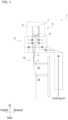
- the oil-agent application unit 20 includes a plurality of oil supply guides 22 (or 32 oil supply guides 22 for example in this embodiment); a plurality of oil supply tubes 24 (or 32 oil supply tubes 24 for example in this embodiment) corresponding to their respective oil supply guides 22; and a plurality of yarn regulating guides 26 (or 32 yarn regulating guides 26 for example in this embodiment).
- the rails 32L and 32R have the above-described sliding sections 16L and 16R slidably arranged in an up-and-down direction.
- the sliding sections 16L and 16R are slid with respect to the rails 32L and 32R so that the sliding sections 16L and 16R can be caused to move up and down with respect to the base member 12 in a substantially vertical direction (i.e., in an up-and-down direction).
- the front face side of the rails 32L and 32R has a 1 mm scale to show a travel distance in an up-and-down direction.
- the B sheaves 44L and 44R are arranged between the A sheaves 42L and 42R and the sliding sections 16L and 16R, respectively.
- the B sheaves 44L and 44R can wind the wires 34L and 34R to apply tension thereto and can change directions of the wires 34L and 34R.
- the B sheaves 44L and 44R are arranged immediately above the A sheaves 42L and 42R at the rear side of the base member 12, respectively.
- the B sheave 44L and the B sheave 44R are arranged at substantially the same height position.
- the B sheaves 44L and 44R are placed so as to be rotatable in a substantially horizontal left-and-right direction as a rotation center.
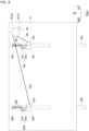
- the B sheaves 44L and 44R change a direction of the wires 34L and 34R outputted from the A sheaves 42L and 42R from a direction toward an upward direction to a direction toward a forward-oblique upward direction (see FIG. 3 ).
- the distance from the spinneret 8 to the oil supply guide 22 (i.e., a position in a height direction) can be substantially equal among a plurality of oil supply guides arranged in a left-and-right direction.
- the spinning system 1 of this embodiment having the tension adjusters 60L and 60R can change a position in an up-and-down direction of at least any one of the A sheave 42L and the A sheave 42R to thereby change the tension of at least any one of the wire 34L and wire 34R.
- such an adjustment can be arranged that allows the plurality of oil supply guides 22 to have substantially the same height position in a left-and-right direction.
- the distance from the spinneret 8 to the oil supply guide 22 can be substantially the same among the plurality of oil supply guides 22 arranged in a left-and-right direction without causing any deviation.
- the winch 40 and the sliding sections 16L and 16R have therebetween the A sheaves 42L and 42R, the B sheaves 44L and 44R, and the C sheaves 46L and 46R.
- the invention is not limited to the above number and layout of the sheaves.
- the oil-agent application unit 20 can be caused by a simple configuration to move up and down through which the operator merely operates the rotation operation section 76 to rotate the rotation roller 74. Furthermore, the wire 34L connected to the sliding section 16L and the wire 34R connected to the sliding section 16R allows, when compared with a case where the wires and the sliding sections are connected at one position, the oil-agent application unit 20 to move up and down in a balanced manner in a left-and-right direction.
- the rear face of the base member 120 is attached with vertically long rectangular support plates 88L and 88R at in substantially the same positions as positions of the rails 32L and 32R (see FIG. 2 ) in a left-and-right direction.
- the upper ends of the support plates 88L and 88R are attached with fixation member 92L and 92R (which will be described later).
- the inner periphery of through hole 923R has a screw section screwed with a screw section formed in the outer periphery of the axis section 944R.
- the adjuster bolt 941R is moved with respect to the planar section 922R in a substantially vertical direction.
- the rotation of the adjustment nut 946R can change the distance of the wire 34R between the planar section 842 of the bracket 84 (see FIG. 7 ) and the planar section 922R of the fixation member 92R to thereby change the tension of the wire 34R.
- the wire 34R fit into the outer cable 86R penetrates through the penetration hole 945R formed in the axis section 944R and has a tip end connected to the sliding section 16R (see FIG. 2 and FIG. 3 ).
- the lifting up and down unit 300 of the third modified example does not include their respective sheaves 42L, 42R, 44L, 44R, 46L, and 46R as has been described with reference to FIG. 3 and FIG. 4 and instead includes the outer cables 86L and 86R into which the wires 34L and 34R are fit.
- the lifting up and down unit 300 can have a simple configuration. Furthermore, no need is no more required to wind the wires 34L and 34R around their respective sheaves 42L, 42R, 44L, 44R, 46L, and 46R for example. Thus, only required is to place the outer cables 86L and 86R into which the wires 34L and 34R are fit, thus providing improved workability.
Landscapes
- Engineering & Computer Science (AREA)
- Mechanical Engineering (AREA)
- Textile Engineering (AREA)
- Spinning Methods And Devices For Manufacturing Artificial Fibers (AREA)
Applications Claiming Priority (2)
| Application Number | Priority Date | Filing Date | Title |
|---|---|---|---|
| JP2021157593 | 2021-09-28 | ||
| JP2022036278 | 2022-03-09 |
Publications (2)
| Publication Number | Publication Date |
|---|---|
| EP4155437A2 true EP4155437A2 (de) | 2023-03-29 |
| EP4155437A3 EP4155437A3 (de) | 2023-05-03 |
Family
ID=83438624
Family Applications (1)
| Application Number | Title | Priority Date | Filing Date |
|---|---|---|---|
| EP22197032.0A Pending EP4155437A3 (de) | 2021-09-28 | 2022-09-22 | Spinnanlage |
Country Status (3)
| Country | Link |
|---|---|
| EP (1) | EP4155437A3 (de) |
| JP (1) | JP7880268B2 (de) |
| CN (1) | CN115874298A (de) |
Citations (1)
| Publication number | Priority date | Publication date | Assignee | Title |
|---|---|---|---|---|
| JP2003013323A (ja) | 2001-06-26 | 2003-01-15 | Toray Ind Inc | 昇降計量給油吐出ノズル装置 |
Family Cites Families (11)
| Publication number | Priority date | Publication date | Assignee | Title |
|---|---|---|---|---|
| JPS5411058B2 (de) * | 1972-09-27 | 1979-05-11 | ||
| DE2822349A1 (de) * | 1978-05-22 | 1979-11-29 | Reiche & Vogel Gmbh | Seilwinde mit selbsthemmendem schneckengetriebe |
| JPS641964Y2 (de) * | 1980-07-15 | 1989-01-18 | ||
| JPS6335817A (ja) * | 1986-07-25 | 1988-02-16 | Teijin Ltd | 溶融紡糸装置の糸掛方法 |
| JP2555462B2 (ja) * | 1990-03-12 | 1996-11-20 | 株式会社三英社製作所 | 開閉器のキャビネットへの取付工具 |
| US5871070A (en) * | 1997-02-21 | 1999-02-16 | Contreras; Hugo | Overhead storage lift assembly |
| KR100490376B1 (ko) * | 2002-07-11 | 2005-05-17 | 정규창 | 필라멘트 실의 냉각 장치 |
| JP4412028B2 (ja) * | 2004-03-30 | 2010-02-10 | 東レ株式会社 | 合成繊維の製造装置 |
| CN202729686U (zh) * | 2012-01-14 | 2013-02-13 | 鲁西军 | 手动蜗轮蜗杆减速箱式提升机 |
| JP2016108698A (ja) * | 2014-12-08 | 2016-06-20 | 東レ株式会社 | 合成繊維の溶融紡糸装置 |
| CN208803175U (zh) * | 2018-09-07 | 2019-04-30 | 福建景丰科技有限公司 | 一种升降式上油导丝装置 |
-
2022
- 2022-09-15 CN CN202211120331.XA patent/CN115874298A/zh active Pending
- 2022-09-15 JP JP2022146721A patent/JP7880268B2/ja active Active
- 2022-09-22 EP EP22197032.0A patent/EP4155437A3/de active Pending
Patent Citations (1)
| Publication number | Priority date | Publication date | Assignee | Title |
|---|---|---|---|---|
| JP2003013323A (ja) | 2001-06-26 | 2003-01-15 | Toray Ind Inc | 昇降計量給油吐出ノズル装置 |
Also Published As
| Publication number | Publication date |
|---|---|
| JP7880268B2 (ja) | 2026-06-25 |
| CN115874298A (zh) | 2023-03-31 |
| JP2023049007A (ja) | 2023-04-07 |
| EP4155437A3 (de) | 2023-05-03 |
Similar Documents
| Publication | Publication Date | Title |
|---|---|---|
| JP4204548B2 (ja) | 紡糸兼巻取り装置 | |
| EP2644548B1 (de) | Aufnahmevorrichtung und Aufnahmeeinrichtung | |
| CN214428402U (zh) | 一种线束绞线装置 | |
| KR100392396B1 (ko) | 트랙의오버헤드라인을설치하는기계 | |
| WO2018044222A1 (en) | A treatment unit for in-line treatment of thread | |
| PL187998B1 (pl) | Maszyna do instalowania przewodu jezdnego | |
| FI108342B (fi) | Kone sõhk÷isen ilmajohdon ajolangan keskeytykset÷ntõ asettamista varten | |
| CZ288403B6 (en) | Machine for travelling on track for laying contact wire | |
| CN223491710U (zh) | 一种自带放线动力的拉丝系统 | |
| CN119480277B (zh) | 一种具有防断线的高速绞线设备 | |
| KR101417645B1 (ko) | 코크스로의 타이로드 교체장치 | |
| CN119489099A (zh) | 自带放线动力的拉丝系统及钨丝冷拉方法 | |
| JP2023049007A (ja) | 紡糸設備 | |
| CN117344419A (zh) | 一种防断线加捻加弹机 | |
| CN210822218U (zh) | 应急传动装置以及索道 | |
| CN215854411U (zh) | 涨力放线导向系统 | |
| CN115557694A (zh) | 一种伸缩旋转式强制分束装置及拉丝方法 | |
| WO2014048266A1 (zh) | 双胞胎型长丝牵伸卷绕装置 | |
| CN222891487U (zh) | 一种防断线的线切割组件及使用该组件的多线切割机 | |
| CN118910748B (zh) | 一种纺丝线张紧度控制用调节装置 | |
| CN110453324A (zh) | 一种电动游车导向机构 | |
| HUT76630A (en) | Wire laying device | |
| CN221543636U (zh) | 一种自动收线机构 | |
| EP3800283B1 (de) | Garnherstellungssystem | |
| CN205772905U (zh) | 可调式电缆滑车及使用该电缆滑车的起重机 |
Legal Events
| Date | Code | Title | Description |
|---|---|---|---|
| PUAI | Public reference made under article 153(3) epc to a published international application that has entered the european phase |
Free format text: ORIGINAL CODE: 0009012 |
|
| STAA | Information on the status of an ep patent application or granted ep patent |
Free format text: STATUS: THE APPLICATION HAS BEEN PUBLISHED |
|
| AK | Designated contracting states |
Kind code of ref document: A2 Designated state(s): AL AT BE BG CH CY CZ DE DK EE ES FI FR GB GR HR HU IE IS IT LI LT LU LV MC MK MT NL NO PL PT RO RS SE SI SK SM TR |
|
| PUAL | Search report despatched |
Free format text: ORIGINAL CODE: 0009013 |
|
| AK | Designated contracting states |
Kind code of ref document: A3 Designated state(s): AL AT BE BG CH CY CZ DE DK EE ES FI FR GB GR HR HU IE IS IT LI LT LU LV MC MK MT NL NO PL PT RO RS SE SI SK SM TR |
|
| RIC1 | Information provided on ipc code assigned before grant |
Ipc: D01D 5/096 20060101ALI20230324BHEP Ipc: D01D 13/02 20060101AFI20230324BHEP |
|
| STAA | Information on the status of an ep patent application or granted ep patent |
Free format text: STATUS: REQUEST FOR EXAMINATION WAS MADE |
|
| 17P | Request for examination filed |
Effective date: 20231103 |
|
| RBV | Designated contracting states (corrected) |
Designated state(s): AL AT BE BG CH CY CZ DE DK EE ES FI FR GB GR HR HU IE IS IT LI LT LU LV MC MK MT NL NO PL PT RO RS SE SI SK SM TR |