EP4153068B1 - Stiftfallenmechanismus für chirurgischen linearen schneider - Google Patents
Stiftfallenmechanismus für chirurgischen linearen schneider Download PDFInfo
- Publication number
- EP4153068B1 EP4153068B1 EP21729520.3A EP21729520A EP4153068B1 EP 4153068 B1 EP4153068 B1 EP 4153068B1 EP 21729520 A EP21729520 A EP 21729520A EP 4153068 B1 EP4153068 B1 EP 4153068B1
- Authority
- EP
- European Patent Office
- Prior art keywords
- proximal
- stapler
- anvil
- cartridge
- pin
- Prior art date
- Legal status (The legal status is an assumption and is not a legal conclusion. Google has not performed a legal analysis and makes no representation as to the accuracy of the status listed.)
- Active
Links
Images


Classifications
-
- A—HUMAN NECESSITIES
- A61—MEDICAL OR VETERINARY SCIENCE; HYGIENE
- A61B—DIAGNOSIS; SURGERY; IDENTIFICATION
- A61B17/00—Surgical instruments, devices or methods
- A61B17/068—Surgical staplers, e.g. containing multiple staples or clamps
- A61B17/072—Surgical staplers, e.g. containing multiple staples or clamps for applying a row of staples in a single action, e.g. the staples being applied simultaneously
- A61B17/07207—Surgical staplers, e.g. containing multiple staples or clamps for applying a row of staples in a single action, e.g. the staples being applied simultaneously the staples being applied sequentially
-
- A—HUMAN NECESSITIES
- A61—MEDICAL OR VETERINARY SCIENCE; HYGIENE
- A61B—DIAGNOSIS; SURGERY; IDENTIFICATION
- A61B17/00—Surgical instruments, devices or methods
- A61B17/11—Surgical instruments, devices or methods for performing anastomosis; Buttons for anastomosis
- A61B17/1114—Surgical instruments, devices or methods for performing anastomosis; Buttons for anastomosis of the digestive tract, e.g. bowels or oesophagus
-
- A—HUMAN NECESSITIES
- A61—MEDICAL OR VETERINARY SCIENCE; HYGIENE
- A61B—DIAGNOSIS; SURGERY; IDENTIFICATION
- A61B17/00—Surgical instruments, devices or methods
- A61B17/11—Surgical instruments, devices or methods for performing anastomosis; Buttons for anastomosis
- A61B17/115—Staplers for performing anastomosis, e.g. in a single operation
-
- A—HUMAN NECESSITIES
- A61—MEDICAL OR VETERINARY SCIENCE; HYGIENE
- A61B—DIAGNOSIS; SURGERY; IDENTIFICATION
- A61B17/00—Surgical instruments, devices or methods
- A61B17/068—Surgical staplers, e.g. containing multiple staples or clamps
-
- A—HUMAN NECESSITIES
- A61—MEDICAL OR VETERINARY SCIENCE; HYGIENE
- A61B—DIAGNOSIS; SURGERY; IDENTIFICATION
- A61B17/00—Surgical instruments, devices or methods
- A61B2017/00367—Details of actuation of instruments, e.g. relations between pushing buttons, or the like, and activation of the tool, working tip, or the like
-
- A—HUMAN NECESSITIES
- A61—MEDICAL OR VETERINARY SCIENCE; HYGIENE
- A61B—DIAGNOSIS; SURGERY; IDENTIFICATION
- A61B17/00—Surgical instruments, devices or methods
- A61B2017/00477—Coupling
-
- A—HUMAN NECESSITIES
- A61—MEDICAL OR VETERINARY SCIENCE; HYGIENE
- A61B—DIAGNOSIS; SURGERY; IDENTIFICATION
- A61B17/00—Surgical instruments, devices or methods
- A61B17/068—Surgical staplers, e.g. containing multiple staples or clamps
- A61B17/072—Surgical staplers, e.g. containing multiple staples or clamps for applying a row of staples in a single action, e.g. the staples being applied simultaneously
- A61B2017/07214—Stapler heads
- A61B2017/07257—Stapler heads characterised by its anvil
- A61B2017/07264—Stapler heads characterised by its anvil characterised by its staple forming cavities, e.g. geometry or material
-
- A—HUMAN NECESSITIES
- A61—MEDICAL OR VETERINARY SCIENCE; HYGIENE
- A61B—DIAGNOSIS; SURGERY; IDENTIFICATION
- A61B17/00—Surgical instruments, devices or methods
- A61B17/068—Surgical staplers, e.g. containing multiple staples or clamps
- A61B17/072—Surgical staplers, e.g. containing multiple staples or clamps for applying a row of staples in a single action, e.g. the staples being applied simultaneously
- A61B2017/07214—Stapler heads
- A61B2017/07271—Stapler heads characterised by its cartridge
-
- A—HUMAN NECESSITIES
- A61—MEDICAL OR VETERINARY SCIENCE; HYGIENE
- A61B—DIAGNOSIS; SURGERY; IDENTIFICATION
- A61B17/00—Surgical instruments, devices or methods
- A61B17/068—Surgical staplers, e.g. containing multiple staples or clamps
- A61B17/072—Surgical staplers, e.g. containing multiple staples or clamps for applying a row of staples in a single action, e.g. the staples being applied simultaneously
- A61B2017/07214—Stapler heads
- A61B2017/07285—Stapler heads characterised by its cutter
-
- A—HUMAN NECESSITIES
- A61—MEDICAL OR VETERINARY SCIENCE; HYGIENE
- A61B—DIAGNOSIS; SURGERY; IDENTIFICATION
- A61B17/00—Surgical instruments, devices or methods
- A61B17/28—Surgical forceps
- A61B17/29—Forceps for use in minimally invasive surgery
- A61B2017/2926—Details of heads or jaws
- A61B2017/2927—Details of heads or jaws the angular position of the head being adjustable with respect to the shaft
-
- A—HUMAN NECESSITIES
- A61—MEDICAL OR VETERINARY SCIENCE; HYGIENE
- A61B—DIAGNOSIS; SURGERY; IDENTIFICATION
- A61B17/00—Surgical instruments, devices or methods
- A61B17/28—Surgical forceps
- A61B17/29—Forceps for use in minimally invasive surgery
- A61B2017/2926—Details of heads or jaws
- A61B2017/2932—Transmission of forces to jaw members
- A61B2017/2933—Transmission of forces to jaw members camming or guiding means
- A61B2017/2936—Pins in guiding slots
-
- A—HUMAN NECESSITIES
- A61—MEDICAL OR VETERINARY SCIENCE; HYGIENE
- A61B—DIAGNOSIS; SURGERY; IDENTIFICATION
- A61B17/00—Surgical instruments, devices or methods
- A61B17/28—Surgical forceps
- A61B17/29—Forceps for use in minimally invasive surgery
- A61B2017/2926—Details of heads or jaws
- A61B2017/2932—Transmission of forces to jaw members
- A61B2017/2933—Transmission of forces to jaw members camming or guiding means
- A61B2017/2937—Transmission of forces to jaw members camming or guiding means with flexible part
-
- A—HUMAN NECESSITIES
- A61—MEDICAL OR VETERINARY SCIENCE; HYGIENE
- A61B—DIAGNOSIS; SURGERY; IDENTIFICATION
- A61B17/00—Surgical instruments, devices or methods
- A61B17/28—Surgical forceps
- A61B17/29—Forceps for use in minimally invasive surgery
- A61B2017/2946—Locking means
Definitions
- a linear surgical stapler generally includes a first half (referred to as a “cartridge half” or “reload half”) having a distal jaw configured to support a staple cartridge (or “reload”), and a second half (referred to as an “anvil half”) having a distal jaw that supports an anvil surface having staple forming features.
- the stapler further includes a moveable clamp lever configured to releasably clamp the stapler halves together.
- the stapler halves are configured to pivot relative to one another to receive and clamp tissue between the two distal jaws when the clamp lever is closed.
- a firing assembly of the stapler is configured to be actuated to cut the clamped layers and simultaneously drive staples through the tissue on either side of the cut line. After firing the stapler, the clamp lever may be opened, and the stapler halves separated to release the severed and stapled tissue.
- EP2532313A2 describes a surgical fastener applying apparatus for applying fasteners to body tissue.
- the apparatus includes a cartridge receiving half-section which includes at its proximal end a pair of vertical support members.
- Each vertical support member includes an elongated vertical slot having a rounded bottom surface.
- Vertical slots are dimensioned to receive protrusions formed on finger of anvil half-section when the anvil half-section is supported on the cartridge receiving half-section during assembly. By positioning protrusions within vertical slots, anvil half-section can be pivoted in a scissor-like action with respect to the cartridge receiving half-section between open and closed positions.
- protrusions have a tear drop profile.
- the present invention provides a surgical stapler in accordance with claim 1. Embodiments are defined in the dependent claims.
- proximal and distal are defined herein relative to a surgeon, or other operator, grasping a surgical instrument having a distal surgical end effector.
- proximal refers to the position of an element arranged closer to the surgeon
- distal refers to the position of an element arranged closer to the surgical end effector of the surgical instrument and further away from the surgeon.
- spatial terms such as “upper,” “lower,” “vertical,” “horizontal,” or the like are used herein with reference to the drawings, it will be appreciated that such terms are used for exemplary description purposes only and are not intended to be limiting or absolute. In that regard, it will be understood that surgical instruments such as those disclosed herein may be used in a variety of orientations and positions not limited to those shown and described herein.
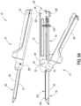
- FIGS. 1-2 show an exemplary linear surgical stapler (10) (also referred to as a "linear cutter”) suitable for use in a variety of cutting and stapling procedures, such as a gastrointestinal anastomosis procedure.
- Linear surgical stapler (10) includes a cartridge half (12) (also referred to as a “reload half”) and an anvil half (14) configured to releasably couple together to clamp tissue therebetween for simultaneous cutting and stapling of the clamped tissue.
- Cartridge half (12) includes an elongate cartridge channel (16) having a proximal frame portion (18) and a distal jaw portion (20).
- Proximal frame portion (18) slidably retains a firing assembly (100) and includes a laterally opposed pair of upright side flanges (22).
- Each side flange (22) includes a vertical slot (24) arranged at a distal end thereof, and a tapered notch (26) arranged at a proximal end thereof.
- An outwardly projecting stiffening rib (28) extends longitudinally between the distal slot (24) and proximal notch (26) of each side flange (22) and is configured to provide the side flange (22) with enhanced stiffness.
- An outwardly flared upper segment (30) defines an upper edge of a proximal portion of each side flange (22) and is configured to facilitate receipt of anvil half (14) by cartridge half (12).
- Each side flange (22) further includes an elongate firing slot (32) extending longitudinally between proximal notch (26) and distal slot (24) along a lower side of side flange (22).
- Elongate firing slots (32) are configured to guide firing assembly (100) between proximal and distal positions. Firing assembly (100) is described in greater detail below in connection with FIG. 4 .
- Distal jaw portion (20) of cartridge channel (16) is configured to receive a staple cartridge (130) (or "reload”), which may be configured in accordance with the teachings of U.S. Pat. App. No. 16/537,005, entitled "Linear Surgical Stapler,” filed on August 9, 2019 .
- Cartridge half (12) further includes a clamp lever (40) (also referred to as a "latch lever”) pivotably coupled to cartridge channel (16) with a clamp lever pivot pin (42), which is arranged in approximate alignment with distal slots (24) of cartridge channel side flanges (22).
- Clamp lever (40) includes an elongate lever arm (44) having a free proximal end (46) and a distal end that is pivotably coupled to a lower portion of cartridge channel (16) with pivot pin (42).
- a pair of opposed jaws (48) extend distally from the distal end of lever arm (44) alongside cartridge channel side flanges (22).
- Each jaw (48) includes a curved slot (50) having a closed proximal end and an open distal end configured to receive a latch pin (68) of anvil half (14), as described below.
- Clamp lever (40) is operable to pivot relative to cartridge channel (16) between an open position in which proximal end (46) of lever arm (44) is spaced from cartridge channel frame portion (18), and a closed position in which proximal end (46) confronts cartridge channel frame portion (18). Actuation of clamp lever (40) from the open position to the closed position operates to capture the opposed lateral ends of latch pin (68) within clamp lever jaw slots (50), and thereby clamp anvil half (14) against cartridge half (12), as shown and described below in connection with FIGS. 5C-5D .
- each jaw slot (50) defines respective upper and lower camming surfaces configured to engage and draw the respective lateral end of latch pin (68) toward cartridge channel (16) as clamp lever (40) is pivotably closed.
- a resilient member shown in the form of a flat spring (52) biases lever arm (44) toward the open position. Accordingly, flat spring (52) promotes disengagement of clamp lever jaws (48) from anvil half latch pin (68) upon initial advancement of clamp lever (40) from the closed position toward the open position.
- clamp lever (40) further includes a latch member (54) arranged at proximal end (46) of lever arm (44).
- Clamp lever latch member (54) is configured to resiliently and releasably engage a proximal end of cartridge channel frame portion (18) and thereby releasably retain clamp lever (40) in the closed position, for instance while stapler (10) is being fired.
- Anvil half (14) of linear surgical stapler (10) includes an elongate anvil channel (60) having a proximal frame portion (62) and a distal jaw portion (64).
- Proximal frame portion (62) includes a laterally opposed pair of upright side flanges (66) that are configured to be received between cartridge channel side flanges (22) when anvil half (14) is coupled with cartridge half (12).
- a distal latch projection in the form of latch pin (68) extends laterally through the distal ends of anvil channel side flanges (66), and a proximal pivot projection in the form of a proximal pin (70) extends laterally through the proximal ends of anvil channel side flanges (66).
- Anvil pins (68, 70) are configured to facilitate coupling of anvil half (14) with cartridge half (12), as described below.
- Distal jaw portion (64) of anvil half (14) supports an anvil plate (72) that defines an anvil surface having a plurality of staple forming pockets (not shown) configured to deform legs of staples ejected by staple cartridge (130) when stapler (10) is fired, for example as described in greater detail in U.S. Pat. App. No. 16/537,005 .
- the anvil surface may be formed integrally with distal jaw portion (64).
- Distal jaw portion (64) of anvil half (14) additionally supports a tapered distal tip member (76).
- distal tip member (76) may be selectively extendable relative to distal jaw portion (64) in accordance with the teachings of U.S. Pat. App. No. 16/165,587, entitled "Decoupling Mechanism for Linear Surgical Stapler," filed on October 19, 2018 .
- linear surgical stapler (10) further includes a plurality of shrouds (56, 78) that cover select portions of stapler (10) and promote effective grip and manipulation of stapler (10) by an operator during use.
- a clamp lever shroud (56) is affixed to and covers an outwardly facing side of clamp lever (40) such that clamp lever shroud (56) is configured to pivot with clamp lever (40) relative to cartridge channel (16).
- an anvil shroud (78) is affixed to and covers an outwardly facing side of anvil channel (60).
- anvil shroud (78) may be coupled with anvil channel (60) in accordance with the teachings of U.S. Pat. App. No.
- shrouds (56, 78) may be coupled with clamp lever (40) and anvil channel (60) in a variety of other suitable manners readily apparent to those of ordinary skill in the art.
- a proximal end of cartridge half (12) includes a retaining assembly (80) configured to releasably retain portions of anvil half (14) and firing assembly (100).
- Retaining assembly (80) of the present example includes an anvil latch member (82) and a detent member (84), both of which are rotatably coupled with a proximal end of cartridge channel (16) via a laterally extending pin (86) arranged proximally of firing slots (32).
- a torsion spring (not shown) is configured to resiliently bias anvil latch member (82) and detent member in opposite rotational directions about the lateral axis defined by pin (86).
- Anvil latch member (82) includes an upper finger (88) configured to releasably capture proximal anvil pin (70) when pin (70) is directed into proximal tapered notches (26) of cartridge channel (16), thereby coupling the proximal ends of stapler halves (12, 14).
- a lower end of anvil latch member (82) defines a release button (90) configured to be depressed by the operator when clamp lever (40) is in the open position to release proximal pin (70) from latch finger (88) and thereby permit separation of the proximal ends of stapler halves (12, 14).
- Detent member (84) includes a distal finger (88) configured to releasably capture the proximal end of a slide block (102) of firing assembly (100) when firing assembly (100) us in a proximal home position, shown in FIG. 3 .
- Detent member (84) further includes a proximal hook (94) configured to releasably capture an upper tip of clamp lever latch member (54) while slide block (102) is positioned distally of its proximal home position, thereby preventing actuation of clamp lever latch member (54) and opening of clamp lever (40) during firing of stapler (10).
- proximal hook (94) of detent member (84) permits clamp lever latch member (54) to rotatably disengage proximal frame portion (18) of cartridge channel (16) in response to actuation by the operator. As a result, clamp lever (40) may then be opened.
- Retaining assembly (80) and related components of cartridge half (12) may be further configured and operable in accordance with at least some of the teachings of U.S. Pat. App. No. 16/102,164, entitled “Firing System for Linear Surgical Stapler,” filed on August 13, 2018 .
- firing assembly (100) of cartridge half (12) includes slide block (102), a pair of actuators (104, 106) (or “firing knobs") pivotably coupled to slide block (102), and a plurality of elongate beams (108, 112) extending distally from slide block (102).
- a pair of side beams (108) are coupled at their proximal ends to a distal end of slide block (102) and terminate distally in a pair of cam ramps (110).
- Cam ramps (110) are configured to engage the undersides of staple drivers (not shown) housed within staple cartridge (130) and actuate staple drivers upwardly to thereby drive (or “fire") staples from cartridge (130) into tissue clamped between staple cartridge (130) and anvil plate (72).
- a center beam (112) is coupled with side beams (108) via a bridge member (114) (or “knife block”) spaced distally from slide block (102).
- Center beam (112) terminates distally in a distally angled knife member (116) having a distal cutting edge (118) configured to cut tissue clamped between the distal portions of stapler halves (12, 14).
- a distal portion of center beam (112) additionally includes an upwardly projecting stop element (120) proximal to knife member (116), and a distally facing lockout projection (122) proximal to stop element (120).
- Each actuator (104, 106) of firing assembly (100) is configured and rotatable relative to slide block (102) between a deployed position and a retracted position such that only one actuator (104, 106) may be deployed at a time, for example as described in greater detail in U.S. Pat. App. No. 16/102,164 .
- an actuator (104, 106) may be driven distally by an operator to actuate firing assembly (100) distally through stapler (10) and thereby simultaneously cut and staple tissue clamped between stapler halves (12, 14).
- staple cartridge (130) includes an elongate cartridge body (132) extending linearly along a longitudinal axis between a proximal end having a pair of hooks (134) and a distal end having a tapered nose (136).
- Proximal hooks (134) are configured to releasably capture clamp lever pivot pin (42) and extend downwardly through corresponding openings formed in a floor of cartridge channel (16) when staple cartridge (130) is seated within distal jaw portion (20) of cartridge channel (16).
- a pair of wing tabs (138) disposed on the lateral sides of cartridge body (132) near the proximal end are configured to facilitate insertion and removal of staple cartridge (130) relative to distal jaw portion (20).
- An upper side of cartridge body (132) defines a deck (140).
- An elongate knife slot (not shown) extends longitudinally through deck (140) along the longitudinal axis of staple cartridge (130) and is configured to slidably receive knife member (116) of firing assembly (100) therethrough in response to distal actuation thereof, described above.
- a rigid tissue gap post (146) is secured at a distal end of the knife slot and protrudes upwardly away from cartridge deck (140).
- a rounded upper end of tissue gap post (146) is configured to contact a distal end of anvil plate (72) and thereby define a tissue gap between cartridge deck (140) and anvil plate (72) when stapler halves (12, 14) are clamped together in the manner described below.
- Staple cartridge (130) may be configured in accordance with U.S. Pat. App. No. 16/537,005 .
- FIGS. 5A-5E show exemplary coupling of stapler halves (12, 14) and subsequent firing of assembled stapler (10) during a surgical procedure.
- clamp lever (40) of cartridge half (12) is provided in the open position so that jaw slots (50) align with vertical slots (24) of cartridge channel side flanges (22).
- firing assembly (100) is maintained in its proximal home position by detent member (84) of retaining assembly (80), as shown in FIG. 3 described above.
- a section of tissue (not shown) to be stapled and cut may be positioned over the top of staple cartridge (130) disposed in distal jaw portion (20) of cartridge half (12).
- the tissue may be positioned over staple cartridge (130) following coupling of the proximal ends of stapler halves (12, 14), described below.
- proximal ends of stapler halves (12, 14) are aligned with one another and proximal anvil pin (70) is directed downwardly into proximal tapered notches (26) of cartridge channel (16) to engage upper finger (88) of anvil latch member (82).
- This engagement forces anvil latch member (82) to resiliently rotate clockwise, thus enabling upper finger (88) of anvil latch member (82) to capture anvil pin (70) and thereby releasably couple together the proximal ends of stapler halves (12, 14), as seen in FIG. 5B .
- anvil half (14) is rotated toward anvil half (14) about proximal anvil pin (70) so that distal latch pin (68) of anvil half (14) is received into vertical slots (24) of cartridge channel side flanges (22) and jaw slots (50) of clamp lever (40).
- Distal jaw portions (20, 64) of stapler halves (12, 14) are now in a partially approximated state such that tissue received therebetween may be finally adjusted before clamping.
- tissue gap post (146) is disposed at a distal end of staple cartridge (130) and is configured to contact a distal end of anvil plate (72) when stapler (10) is in the fully clamped state shown in FIG. 5D , for example as described in greater detail in U.S. Pat. App. No. 16/537,005 .
- stapler (10) may be fired by driving a deployed actuator (104, 106) of firing assembly (100) distally along proximal frame portion (18) of cartridge half (12). As described above in connection with FIG. 4 , this action causes elongate beams (108, 112) of firing assembly (100) to translate distally through corresponding channels formed in staple cartridge (130) and thereby fire staples into the clamped tissue via cam ramps (110) and staple drivers, and simultaneously cut the clamped tissue with knife member (116). Following completion of the firing stroke, firing assembly (100) is returned to its proximal home position via the actuator (104, 106).
- Clamp lever latch member (54) may then be depressed to release the proximal end of clamp lever (40) from cartridge channel (16), thus permitting clamp lever (40) to be re-opened. Then, release button (90) of retaining assembly (80) may be depressed to release anvil half (14) from cartridge half (12) so that stapler halves (12, 14) may be separated from one another, thereby releasing the newly stapled and severed tissue.
- stapler (10) may include features that promote decoupling of stapler halves (12, 14) similar to those features disclosed in U.S. Pat. App. No. 16/165,587 .
- a pivotable coupling is established between the proximal ends of stapler halves (12, 14) when proximal anvil pin (70) is captured by upper finger (88) of anvil latch member (82).
- Release button (90) of retaining assembly (80) may be subsequently depressed to rotate upper finger (88) and thereby release anvil half (14) from cartridge half (12) so that stapler halves (12, 14) may be separated from one another.
- a linear surgical stapler with an open state in which respective elongate members of the stapler halves assume a predetermined maximum angular orientation relative to one another and remain releasably coupled together at their proximal ends (also referred to as a "hang open” or “open aperture” state), such that the stapler in the open state can be easily manipulated by an operator with a single hand. It may also be desirable for the operator to be able to separate the halves by intuitively actuating a linearly translatable mechanism to release the proximal pin. Such a configuration may protect against unintentional decoupling of the stapler halves during single-handed manipulation of the stapler while also simplifying desired separations of the stapler halves.
- the following description provides several illustrative examples of variations of surgical stapler (10) that may provide such functionality.
- FIGS. 6-8 show an exemplary surgical stapler (210) including a cartridge half (212) and an anvil half (214) configured to remain releasably coupled together at their proximal ends in an open state in which respective elongate members of the stapler halves (212, 214) assume a predetermined maximum angular orientation relative to one another, and further configured to be pulled or pried apart from each other to allow separation of stapler halves (212, 214) from each other.
- Stapler (210) is similar to stapler (10) described above except as otherwise described below.
- Cartridge half (212) of linear surgical stapler (210) includes an elongate cartridge channel (216) having a proximal frame portion (218) and a distal jaw portion (220).
- Proximal frame portion (218) slidably retains a firing assembly (not shown) and includes a laterally opposed pair of upright side flanges (222).
- Each side flange (222) includes a vertical slot (224) arranged at a distal end thereof, and a notch (226) arranged at a proximal end thereof.
- each side flange (222) extends upwardly to varying degrees along the length of proximal frame portion (218), such that the proximal portion of each side flange (222) defining the respective notch (226) is generally goalpost-shaped. It will be appreciated that side flanges (222) may be configured in any other suitable manner. For example, one or both side flanges (222) may extend upwardly in a more uniform manner along the length of proximal frame portion (218) as shown in connection with stapler (10).
- Cartridge half (212) further includes a clamp lever (240) pivotably coupled to cartridge channel (216) with a clamp lever pivot pin (242), which is arranged in approximate alignment with distal slots (224) of cartridge channel side flanges (222).
- Clamp lever (240) includes an elongate lever arm (244) having a free proximal end (246) and a distal end that is pivotably coupled to a lower portion of cartridge channel (216) with pivot pin (242).
- a pair of opposed jaws (248) extend distally from the distal end of lever arm (244) alongside cartridge channel side flanges (222).
- Each jaw (248) includes a curved slot (250) having a closed proximal end and an open distal end configured to receive a latch pin (268) of anvil half (214), as described above in connection to FIGS. 5A-5E .
- Anvil half (214) of linear surgical stapler (210) includes an elongate anvil channel (260) having a proximal frame portion (262) and a distal jaw portion (264).
- Proximal frame portion (262) includes a laterally opposed pair of upright side flanges (266) that are configured to be received between cartridge channel side flanges (222) when anvil half (214) is coupled with cartridge half (212).
- a distal latch projection in the form of latch pin (268) extends laterally through the distal ends of anvil channel side flanges (266), and a proximal pivot projection in the form of a generally pear-shaped proximal pin (270) extends laterally through the proximal ends of anvil channel side flanges (266).
- Distal jaw portion (264) of anvil half (214) supports an anvil plate (272) that defines an anvil surface having a plurality of staple forming pockets (not shown) configured to deform legs of staples ejected by a staple cartridge (not shown) when stapler (210) is fired.
- cartridge half (212) further includes a longitudinally translatable locking member or slide (280) defining a distally open-ended aperture (282) configured to releasably retain proximal anvil pin (270).
- the illustrated slide (280) further includes a laterally opposed pair of detent members (284) positioned below a lower peripheral edge of aperture (282) and extending laterally inwardly for facilitating releasable coupling of slide (280) to cartridge channel (216).
- cartridge half (212) further includes laterally opposed pairs of proximal and distal indent members (285a, 285b) positioned on respective side flanges (222) and configured to selectively receive respective detent members (284) with a friction fit or a snap fit for coupling slide (280) to cartridge channel (216).
- selective engagement between detent members (284) and distal indent members (285b) may secure slide (280) to the goalpost-shaped proximal portions of side flanges (222) with aperture (282) longitudinally aligned with notches (226) to define a "locked" state of slide (280), as shown in FIG. 7A .
- detent members (284) and proximal indent members (285a) may secure slide (280) to the goalpost-shaped proximal portions of side flanges (222) with aperture (282) positioned proximally relative to notches (226) to define an "unlocked" state of slide (280), as shown in FIG. 7B .
- aperture (282) of slide (280) is configured to cooperate with notches (226) to releasably and pivotably capture proximal anvil pin (270) when proximal anvil pin (270) is received within proximal notches (226) with slide (280) in the locked state, thereby coupling the proximal ends of stapler halves (212, 214). More particularly, aperture (282) is sized and configured to permit rotation of proximal anvil pin (270) therewithin to accommodate rotation of anvil half (214) about proximal anvil pin (270).
- an upper peripheral edge of aperture (282) may be configured to rotatably sandwich proximal anvil pin (270) against closed ends of notches (226) to prevent proximal anvil pin (270) from being inadvertently dislodged from notches (226) while slide (280) is in the locked state.
- the upper peripheral edge of aperture (282) may be configured to continuously confront proximal anvil pin (270) during rotation of anvil half (214) away from cartridge half (212) to a predetermined maximum orientation whereat a narrow upper portion of proximal anvil pin (270) abuts proximal surfaces of notches (226) to assist in preventing inadvertent decoupling of stapler halves (212, 214), such as during single-handed manipulation of stapler (210).
- aperture (282) and proximal anvil pin (270) may assist in defining an open state of stapler (210) by allowing cartridge half (212) and anvil half (214) to remain releasably coupled together at their proximal ends while their distal ends are spaced apart by an open gap.
- interaction between aperture (282) and proximal anvil pin (270) may assist in reliably coupling anvil half (214) to cartridge half (212) during rotation of anvil half (214) about proximal anvil pin (270) between the open and clamped states.
- detent members (284) are sized relative to proximal and distal indent members (285a, 285b) (e.g., in the lateral direction) to permit selective overriding of the interaction therebetween upon application of a threshold longitudinal force applied between slide (280) and cartridge channel (216) to thereby withdraw detent members (284) from indent members (285a, 285b) for moving slide (280) between the locked and unlocked states, and/or for separating slide (280) from cartridge channel (216), as indicated by first and second arrows (A1, A2) in FIGS. 7A and 8 , respectively.
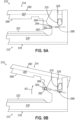
- FIGS. 9A-9C show another exemplary surgical stapler (310) including a cartridge half (312) and an anvil half (314) that are configured in such a manner, and which are similar in structure and function to stapler (210) described above except as otherwise described below.
- Cartridge half (312) includes an elongate cartridge channel (316) having a proximal frame portion (318) including a laterally opposed pair of upright side flanges (322), each including a notch (326) arranged at a proximal end thereof.
- Anvil half (314) includes an elongate anvil channel (360) having a proximal frame portion (362) including a laterally opposed pair of upright side flanges (366) that are configured to be received between cartridge channel side flanges (322) when anvil half (314) is coupled with cartridge half (312).
- a proximal pivot projection in the form of a generally pear-shaped proximal pin (370) extends laterally through the proximal ends of anvil channel side flanges (366).
- a proximal end of anvil half (314) includes a laterally opposed pair of slots (382) extending longitudinally along respective side flanges (366) between closed ends slightly below and distal relative to proximal anvil pin (370).
- Anvil half (314) further includes a longitudinally translatable pin (384) positioned within and extending laterally outwardly from slots (382) such that lateral ends of pin (384) are capable of engaging cartridge side flanges (322).
- anvil half (314) also includes a resilient member in the form of a tension or extension spring (388) longitudinally aligned with slots (382) and having a proximal end fixed relative to anvil side flanges (366) and a distal end fixed relative to pin (384), such that spring (388) is configured to bias pin (384) toward the proximal closed ends of slots (382).
- a tension or extension spring (388) longitudinally aligned with slots (382) and having a proximal end fixed relative to anvil side flanges (366) and a distal end fixed relative to pin (384), such that spring (388) is configured to bias pin (384) toward the proximal closed ends of slots (382).
- a proximal end of cartridge half (312) includes a laterally opposed pair of camming surfaces (389) extending distally from the goalpost-shaped proximal portions of respective cartridge side flanges (322) and configured to selectively engage pin (384) for coupling stapler halves (312, 314).
- camming surfaces (389) are each generally rounded toward a distal apex and include a relatively steep lower portion and a relatively gradual upper portion.
- camming surfaces (389) of cartridge half (312) are configured to cooperate with proximally-biased pin (384) to assist in maintaining proximal anvil pin (370) within proximal notches (326), thereby coupling the proximal ends of stapler halves (312, 314).
- spring (388) is configured to promote seating of pin (370) at lower bases of camming surfaces (389) and to resist distal movement of pin (370) along the steep lower portions of camming surfaces (389) toward the distal apexes thereof, thereby biasing stapler halves (312, 314) toward the clamped state.
- camming surfaces (389) of cartridge half (312) are further configured to cooperate with proximally-biased pin (384) to permit decoupling of stapler halves (312, 314) upon application of a threshold rotational force applied between stapler halves (312, 314) sufficient to overcome the proximal biasing of pin (384) and thereby direct pin (384) toward the distal closed ends of slots (382) and over the distal apexes of camming surfaces (389) to the gradual upper portions thereof, as indicated by third arrow (A3) in FIG. 9B .
- pin (384) positioned at or over the distal apexes of camming surfaces (389), anvil half (314) may be freely separable from cartridge half (312), as indicated by fourth arrow (A4) in FIG. 9C .
- FIGS. 10A-10C show another exemplary surgical stapler (410) including a cartridge half (412) and an anvil half (414) that are configured in such a manner, and which are similar in structure and function to stapler (210) described above except as otherwise described below.
- Cartridge half (412) includes an elongate cartridge channel (416) having a proximal frame portion (418) and a distal jaw portion (not shown).
- Proximal frame portion (418) includes a laterally opposed pair of upright side flanges (422), each including a notch (426) arranged at a proximal end thereof.
- Anvil half (414) includes an elongate anvil channel (460) having a proximal frame portion (462) and a distal jaw portion (not shown).
- Proximal frame portion (462) includes a laterally opposed pair of upright side flanges (466) that are configured to be received between cartridge channel side flanges (422) when anvil half (414) is coupled with cartridge half (412).
- a distal latch projection in the form of latch pin extends laterally through the distal ends of anvil channel side flanges (466), and a proximal pivot projection in the form of a generally pear-shaped proximal pin (470) extends laterally through the proximal ends of anvil channel side flanges (466).
- cartridge half (412) further includes a longitudinally translatable locking member or slide (480) having a longitudinal base (481), an arm (483) extending upwardly from a proximal end of base (481), and an upper finger or hook portion (484) extending distally from an upper end of arm (483) and configured to releasably retain proximal anvil pin (470).
- slide (480) further includes a button (485) extending laterally outwardly from base (481) and configured to assist an operator with gripping and manipulating slide (480).
- Cartridge half (412) also includes a cavity (486) configured to receive slide (480) and accommodate longitudinal translation of slide (480) therein between a distal locked state, as shown in FIGS.
- cartridge half (412) further includes an aperture (487) configured to permit button (485) to extend laterally outwardly therethrough and accommodate longitudinal translation thereof corresponding to translation of slide (480) between the locked and unlocked states.
- button (485) and aperture (487) are both positioned at a side of cartridge half (412) with button surface (485) facing laterally outwardly, such that button surface (485) may be accessible via aperture (487) irrespective of whether a clamp lever (not shown) of stapler (410) is in an open or closed position.
- cartridge half (412) also includes a resilient member in the form of a torsion spring (488) positioned between base (481) and an interior surface of cavity (486), such that spring (488) is configured to bias slide (480) distally toward the locked state.
- a torsion spring 488 positioned between base (481) and an interior surface of cavity (486), such that spring (488) is configured to bias slide (480) distally toward the locked state.
- hook portion (484) of slide (480) is configured to cooperate with notches (426) to releasably and pivotably capture proximal anvil pin (470) when proximal anvil pin (470) is received within proximal notches (426) with slide (480) in the locked state, thereby coupling the proximal ends of stapler halves (412, 414). More particularly, hook portion (484) is sized and configured to permit rotation of proximal anvil pin (470) thereunder to accommodate rotation of anvil half (414) about proximal anvil pin (470).
- hook portion (484) of slide (480) may be configured to rotatably sandwich proximal anvil pin (470) against closed ends of notches (426) to prevent proximal anvil pin (470) from being inadvertently dislodged from notches (426) while slide (480) is in the locked state.
- hook portion (484) of slide (480) may be configured to continuously confront proximal anvil pin (470) during rotation of anvil half (414) away from cartridge half (412) to a predetermined maximum orientation whereat a narrow upper portion of proximal anvil pin (470) abuts proximal surfaces of notches (426) and/or a distal surface of arm (483) to assist in preventing inadvertent decoupling of stapler halves (412, 414), such as during single-handed manipulation of stapler (410).
- hook portion (484) and proximal anvil pin (470) may assist in defining an open state of stapler (410) by allowing cartridge half (412) and anvil half (414) to remain releasably coupled together at their proximal ends while their distal ends are spaced apart by an open gap, as shown in FIG. 10B .
- interaction between hook portion (484) and proximal anvil pin (470) may assist in reliably coupling anvil half (414) to cartridge half (412) during rotation of anvil half (414) about proximal anvil pin (470) between the open and clamped states.
- button (485) may be configured to permit an operator to apply a threshold proximal force to slide (480) sufficient to overcome the distal biasing of slide (480) and thereby translate slide (480) to the unlocked state such that hook portion (484) is proximally withdrawn from proximal anvil pin (470) for separating stapler halves (412, 414), as indicated by fifth arrow (A5).
- proximal pin (470) and slide (480) may be provided in which proximal pin (470) is provided on cartridge half (412) and slide (480) is provided on anvil half (414).
- proximal pin (470) or any other suitable proximal pivot projection
- the proximal pin slide may include a button portion configured to assist an operator with gripping and manipulating the proximal pin slide.
- the operator may initially couple stapler halves (412, 414) together at their proximal ends by positioning proximal anvil pin (470) within notches (426) while applying a threshold proximal force to slide (480) to maintain slide (480) in the unlocked state, and by subsequently releasing slide (480) to allow spring (488) to urge slide (480) to the locked state to thereby capture proximal anvil pin (470) between hook portion (484) and the closed ends of notches (426).
- the operator may then rotate anvil half (414) relative to cartridge half (412) about proximal anvil pin (470) as desired, such as between the open and clamped states, while stapler halves (412, 414) remain reliably coupled to each other to perform a cutting and/or stapling procedure.
- the operator may selectively separate stapler halves (412, 414) from each other by translating slide (480) to the unlocked state to thereby release proximal anvil pin (470) from hook portion (484).
- FIG. 11 shows another exemplary surgical stapler (510) including a cartridge half (512) and an anvil half (514) that are configured in such a manner, and which are similar in structure and function to stapler (210) described above except as otherwise described below.
- Cartridge half (512) includes an elongate cartridge channel (516) having a proximal frame portion (518) and a distal jaw portion (not shown).
- Proximal frame portion (518) includes a laterally opposed pair of upright side flanges (522).
- Anvil half (514) includes an elongate anvil channel (560) having a proximal frame portion (562) and a distal jaw portion (not shown).
- Proximal frame portion (562) includes a laterally opposed pair of upright side flanges (566) that are configured to be received between cartridge channel side flanges (522) when anvil half (514) is coupled with cartridge half (512).
- a proximal pivot projection in the form of a round (e.g., circular) proximal pin (570) extends laterally between the proximal ends of cartridge channel side flanges (522).
- anvil half (514) further includes a longitudinally translatable locking member or slide (580) having a J-shaped finger or hook portion (584) extending distally from a button (585) and configured to releasably retain proximal cartridge pin (570).
- Anvil half (512) also includes a cavity (586) configured to receive slide (580) and accommodate longitudinal translation of slide (580) therein between proximal locked and distal unlocked states.
- anvil half (514) also includes a resilient member in the form of a compression spring (588) positioned between hook portion (584) and an interior surface of cavity (586), such that spring (588) is configured to bias slide (580) proximally toward the locked state.
- hook portion (584) of slide (580) is configured to releasably and pivotably capture proximal cartridge pin (570) when in the locked state, thereby coupling the proximal ends of stapler halves (512, 514).
- Button (585) may be configured to permit an operator to apply a threshold distal force to slide (580) sufficient to overcome the proximal biasing of slide (580) and thereby translate slide (580) to the unlocked state such that hook portion (584) is distally withdrawn from proximal cartridge pin (570) for separating stapler halves (512, 514), as indicated by sixth arrow (A6).
- FIG. 12 shows another exemplary surgical stapler (610) including a cartridge half (612) and an anvil half (614) that are configured in such a manner, and which are similar in structure and function to stapler (210) described above except as otherwise described below.
- Cartridge half (612) includes an elongate cartridge channel (616) having a proximal frame portion (618) including a laterally opposed pair of upright side flanges (622), each including a notch (626) arranged at a proximal end thereof.
- Anvil half (614) includes an elongate anvil channel (660) having a proximal frame portion (662) including a laterally opposed pair of upright side flanges (666) that are configured to be received between cartridge channel side flanges (622) when anvil half (614) is coupled with cartridge half (612).
- a proximal pivot projection in the form of a generally pear-shaped proximal pin (670) extends laterally through the proximal ends of anvil channel side flanges (666).
- cartridge half (612) further includes a C-clip (679) longitudinally aligned with notches (626) and configured to releasably retain proximal anvil pin (670).
- Cartridge half (612) also includes an L-shaped ejector lever (680) pivotably coupled to side flanges (622) slightly below and proximal relative to notches (626), such that lever (680) may be pivotable between a generally vertical locked state and a generally angled unlocked state, as indicated by seventh arrow (A7).
- lever (680) is configured to urge proximal anvil pin (670) upwardly out of C-clip (679) when in the unlocked state for separating stapler halves (612, 614), as indicated by eighth arrow (A8).
- cartridge half (612) may also include a resilient member (e.g., a torsion spring) configured to bias lever (680) toward the locked state.
- a resilient member e.g., a torsion spring
- FIG. 13 shows another exemplary surgical stapler (710) including a cartridge half (712) and an anvil half (714) that are configured in such a manner, and which are similar in structure and function to stapler (210) described above except as otherwise described below.
- Cartridge half (712) includes an elongate cartridge channel (716) having a proximal frame portion (718) including a laterally opposed pair of upright side flanges (722), each including a notch (726) arranged at a proximal end thereof.
- Anvil half (714) includes an elongate anvil channel (760) having a proximal frame portion (762) including a laterally opposed pair of upright side flanges (766) that are configured to be received between cartridge channel side flanges (722) when anvil half (714) is coupled with cartridge half (712).
- a proximal pivot projection in the form of a generally pear-shaped proximal pin (770) extends laterally through the proximal ends of anvil channel side flanges (766).
- cartridge half (712) further includes a C-clip (779) longitudinally aligned with notches (726) and configured to releasably retain proximal anvil pin (770).
- Cartridge half (712) also includes a J-shaped ejector slide (780) slidably coupled to side flanges (722) slightly below and proximal relative to notches (726), such that slide (780) may be translatable between a proximal locked state and a distal unlocked state, as indicated by ninth arrow (A9).
- slide (780) is configured to urge proximal anvil pin (770) upwardly out of C-clip (779) when in the unlocked state for separating stapler halves (712, 714), as indicated by tenth arrow (A10).
- cartridge half (712) may also include a resilient member (e.g., a compression spring) configured to bias slide (780) toward the locked state.
- a resilient member e.g., a compression spring
- FIGS. 14A-14B show another exemplary surgical stapler (810) including a cartridge half (812) and an anvil half (814) that are configured in such a manner, and which are similar in structure and function to stapler (210) described above except as otherwise described below.
- Cartridge half (812) includes an elongate cartridge channel (816) having a proximal frame portion (818) including a laterally opposed pair of upright side flanges (822).
- Anvil half (814) includes an elongate anvil channel (860) having a proximal frame portion (862) including a laterally opposed pair of upright side flanges (866) that are configured to be received between cartridge channel side flanges (822) when anvil half (814) is coupled with cartridge half (812).
- a proximal pivot projection in the form of a round (e.g., circular) proximal pin (870) extends laterally between the proximal ends of cartridge channel side flanges (822).
- an anvil shroud (878) is affixed to and covers an outwardly facing side of anvil channel (860).
- anvil half (814) further includes a longitudinally translatable locking member or slide (880) having a base portion (881) including a stepped notch (882) defining a hook portion (884). More particularly, notch (882) includes a generally downwardly-facing open end and a generally proximally-facing closed end configured to releasably retain proximal cartridge pin (870).
- slide (880) further includes a button (885) extending upwardly from base (881) and configured to assist an operator with gripping and manipulating slide (880).
- the illustrated slide (880) also includes a generally convex proximal camming surface (889).
- Anvil half (812) also includes a cavity (886) configured to receive slide (880) and accommodate longitudinal translation of slide (880) therein between a proximal locked state, as shown in FIG. 14A , and a distal unlocked state, as shown in FIG. 14B .
- anvil shroud (878) includes an aperture (887) configured to permit button (885) to extend upwardly therethrough and accommodate longitudinal translation thereof corresponding to translation of slide (880) between the locked and unlocked states.
- anvil half (814) also includes a resilient member in the form of a compression spring (888) positioned between base (881) and an interior surface of cavity (886), such that spring (888) is configured to bias slide (880) proximally toward the locked state.
- the closed end of notch (882) of slide (880) is configured to releasably and pivotably capture proximal cartridge pin (870) when in the locked state, thereby coupling the proximal ends of stapler halves (812, 814).
- Button (885) may be configured to permit an operator to apply a threshold distal force to slide (880) sufficient to overcome the proximal biasing of slide (880) and thereby translate slide (880) to the unlocked state such that the closed end of notch (882) is distally withdrawn from proximal cartridge pin (870) for separating stapler halves (812, 814).
- camming surface (889) of slide (880) may be configured to interact with a corresponding angled camming surface (891) positioned on cartridge half (812) to urge slide (880) distally in response to a threshold separation force being applied at the proximal ends of stapler halves (812, 814), such as via rotation of anvil half (814) away from cartridge half (812).
- camming surfaces (889, 891) may be configured to urge slide (880) to the unlocked state in response to rotation of anvil half (814) away from cartridge half (812) to a predetermined maximum orientation for decoupling of stapler halves (812, 814).
- FIGS. 15A-15C show another exemplary surgical stapler (910) including a cartridge half (912) and an anvil half (914) that are configured in such a manner, and which are similar in structure and function to stapler (210) described above except as otherwise described below.
- Cartridge half (912) includes an elongate cartridge channel (916) having a proximal frame portion (918) including a laterally opposed pair of upright side flanges (922).
- Anvil half (914) includes an elongate anvil channel (960) having a proximal frame portion (962) including a laterally opposed pair of upright side flanges (966) that are configured to be received between cartridge channel side flanges (922) when anvil half (914) is coupled with cartridge half (912).
- a proximal pivot projection in the form of a round (e.g., circular) proximal pin (970) extends laterally between the proximal ends of cartridge channel side flanges (922).
- an anvil shroud (978) is affixed to and covers an outwardly facing side of anvil channel (960).
- anvil half (914) further includes a longitudinally translatable locking member or slide (980) including a stepped notch (982) defining a hook portion (984). More particularly, notch (982) includes a generally downwardly-facing open end and a generally proximally-facing closed end configured to releasably retain proximal cartridge pin (970).
- slide (980) further includes a proximal button surface (985) configured to assist an operator with gripping and manipulating slide (980).
- the illustrated slide (980) also includes generally angled proximal and distal camming surfaces (989, 991) defined by notch (982).
- proximal camming surface (989) is inclined distally in an upward direction from a proximal lower edge of notch (982), and distal camming surface (991) is inclined proximally in an upward direction from a distal lower edge of notch (982) (e.g., along a proximal end of hook portion (984)).
- Anvil half (914) also includes a cavity (986) configured to receive slide (980) and accommodate longitudinal translation of slide (980) therein between a proximal locked state, as shown in FIG. 15B , and a distal unlocked state, as shown in FIG. 15C .
- anvil shroud (978) includes an aperture (987) configured to permit button surface (985) to extend proximally therethrough for allowing an operator to access button surface (985).
- button surface (985) and aperture (987) are both positioned at a proximal end of anvil half (914) with button surface (985) facing proximally, such that button surface (985) may be accessible via aperture (987) irrespective of whether a clamp lever (not shown) of stapler (910) is in an open or closed position.
- button surface (985) and aperture (987) may remain unobstructed by the clamp lever when the clamp lever is in a closed position in which a proximal end of the clamp lever confronts cartridge channel frame portion (918).
- anvil half (914) also includes a resilient member in the form of a compression spring (988) positioned between slide (980) and an interior surface of cavity (986), such that spring (988) is configured to bias slide (880) proximally toward the locked state.
- a resilient member in the form of a compression spring (988) positioned between slide (980) and an interior surface of cavity (986), such that spring (988) is configured to bias slide (880) proximally toward the locked state.
- the closed end of notch (982) of slide (980) is configured to releasably and pivotably capture proximal cartridge pin (970) when in the locked state, thereby coupling the proximal ends of stapler halves (912, 914).
- Distal camming surface (991) of slide (980) may be configured to interact with proximal cartridge pin (970) to initially urge slide (980) distally during coupling of stapler halves (912, 914), as indicated by eleventh and twelfth arrows (A11, A12) in FIG.
- spring (988) may be configured to subsequently bias slide (880) toward the locked state to seat proximal cartridge pin (970) at the closed end of notch (982), as indicated by thirteenth arrow (A13) in FIG. 15B .
- Button surface (985) may be configured to permit an operator to apply a threshold distal force to slide (980) sufficient to overcome the proximal biasing of slide (980) and thereby translate slide (980) to the unlocked state such that the closed end of notch (982) is distally withdrawn from proximal cartridge pin (970) for separating stapler halves (912, 914).
- proximal camming surface (989) of slide (980) may be configured to interact with proximal cartridge pin (970) to urge the proximal end of anvil half (914) upwardly away from the proximal end of cartridge half (912) during translation of slide (980) toward the unlocked state to thereby separate stapler halves (912, 914), as indicated by fourteenth arrow (A14) in FIG. 15C .
- proximal pin (970) and slide (980) may be provided in which proximal pin (970) is provided on anvil half (912) and slide (980) is provided on cartridge half (914).
- the operator may initially couple stapler halves (912, 914) together at their proximal ends by lowering anvil half (914) toward cartridge half (912) such that distal camming surface (991) and proximal cartridge pin (970) cooperate to urge slide (980) distally and allow proximal cartridge pin (970) to enter notch (982), and spring (988) may subsequently bias slide (880) toward the locked state to seat proximal cartridge pin (970) at the closed end of notch (982).
- the operator may then rotate anvil half (914) relative to cartridge half (912) about proximal cartridge pin (970) as desired, such as between open and clamped states, while stapler halves (912, 914) remain reliably coupled to each other to perform a cutting and/or stapling procedure.
- the operator may selectively separate stapler halves (912, 914) from each other by translating slide (980) to the unlocked state to thereby release proximal cartridge pin (970) from the closed end of notch (982) and such that proximal camming surface (989) and proximal cartridge pin (970) cooperate to urge the proximal end of anvil half (914) upwardly away from the proximal end of cartridge half (912).
- FIG. 16 shows an exemplary locking member (1080) that is configured in such a manner, and which may be incorporated into a stapler similar in structure and function to stapler (210) described above except as otherwise described below.
- Locking member (1080) includes a longitudinally opposed pair of longitudinally translatable proximal and distal slides (1080a, 1080b).
- slides (1080a, 1080b) each include a longitudinal arm (1083a, 1083b) and a longitudinally-inward finger or hook portion (1084a, 1084b) configured to cooperate with each other to releasably retain a proximal pivot projection (e.g., a proximal anvil pin or a proximal cartridge pin) of the stapler.
- a proximal pivot projection e.g., a proximal anvil pin or a proximal cartridge pin
- slides (1080a, 1080b) each further include a longitudinally-outward button (1085a, 1085b) configured to assist an operator with gripping and manipulating the respective slide (1080a, 1080b).
- Slides (1080a, 1080b) may be configured to be received by one or more cavities provided in a cartridge half or an anvil half of the stapler to accommodate longitudinal translation of slides (1080a, 1080b) therein relative to each other between a longitudinally outward locked state and a longitudinally inward unlocked state, as indicated by fifteenth arrow (A15).
- a cartridge half or anvil half may further include an aperture (e.g., in a shroud thereof) configured to permit buttons (1085a, 1085b) to extend outwardly therethrough and accommodate longitudinal translation thereof corresponding to translation of the respective slides (1080a, 1080b) between the locked and unlocked states.
- locking member (1080) also includes a longitudinally opposed pair of resilient members in the form of proximal and distal compression springs (1088a, 1088b) positioned between slides (1080a, 1080b), such that springs (1088a, 1088b) are configured to bias slides (1080a, 1080b) longitudinally outwardly relative to each other toward the locked state.
- hook portions (1084a, 1084b) of slides (1080a, 1080b) are configured to cooperate with each other to releasably and pivotably capture the proximal pivot projection of the stapler when in the locked state, thereby coupling the proximal ends of the stapler halves.
- Buttons (1085a, 1085b) may be configured to permit an operator to apply threshold longitudinally-inward forces to slides (1080a, 1080b) sufficient to overcome the longitudinally-outward biasing of slides (1080a, 1080b) and thereby translate slides (1080a, 1080b) to the unlocked state such that hook portions (1085a, 1085b) are longitudinally withdrawn from the proximal pivot projection for separating the stapler halves.
- hook portions (1085a, 1085b) may include angled or rounded camming surfaces (not shown) configured to interact with the proximal pivot projection to urge slides (1080a, 1080b) longitudinally inwardly in response to a threshold separation force being applied at the proximal ends of the stapler halves, such as via rotation of the stapler halves away from each other.
- camming surfaces may be configured to urge slides (1080a, 1080b) to the unlocked state in response to rotation of the stapler halves away from each other to a predetermined maximum orientation for decoupling of the stapler halves.
- FIGS. 17A-17B show another exemplary surgical stapler (1110) including a cartridge half (1112) and an anvil half (1114) that are configured in such a manner, and which are similar in structure and function to stapler (210) described above except as otherwise described below.
- Cartridge half (1112) includes an elongate cartridge channel (1116) having a proximal frame portion (1118) including a laterally opposed pair of upright side flanges (1122), each including a tapered notch (1126) arranged at a proximal end thereof.
- Anvil half (1114) includes an elongate anvil channel (1160) having a proximal frame portion (1162) including a laterally opposed pair of upright side flanges (1166) that are configured to be received between cartridge channel side flanges (1122) when anvil half (1114) is coupled with cartridge half (1112).
- a proximal pivot projection in the form of a round (e.g., circular) proximal pin (1170) extends laterally between the proximal ends of anvil channel side flanges (1166). Additionally, anvil half (1114) includes a proximal anvil channel extension (1179) projecting proximally from a proximal end of anvil channel (1160).
- proximal frame portion (1118) of cartridge channel (1116) supports a proximal retaining assembly (1180) generally similar to those described in U.S. Pub. No. 2020/0046351, entitled “Decoupling Mechanism for Linear Surgical Stapler,” published on February 13, 2020 , the disclosure of which is incorporated by reference herein.
- An anvil latch member (1182) of proximal retaining assembly (1180) includes a generally cylindrical body (1184), a latch finger (1186) extending upwardly from body (1184), a release button (1188) extending downwardly from body (1184), and a torque arm (1190) extending proximally and laterally outwardly from body (1184).
- anvil half (1114) is configured to be pivoted open relative to cartridge half (1112) through a first range of motion about a first pivot axis defined by proximal anvil pin (1170) to a predetermined degree at which proximal anvil channel extension (1179) directly contacts an upper surface of torque arm (1190).
- pivoting anvil half (1114) further open through a second range of motion about proximal anvil pin (1170) causes proximal anvil channel extension (1179) to drive torque arm (1190) downwardly, as indicated by sixteenth arrow (A16).
- torque arm (1190) causes anvil latch member (1182) to rotate such that latch finger (1186) moves proximally to release proximal anvil pin (1170).
- torque arm (1190) and proximal anvil channel extension (1179) cooperate to define a decoupling mechanism that is similar in function to those described in U.S. Pub. No. 2020/0046351 , incorporated by reference above.
- further opening of anvil half (1114) causes anvil half (1114) to pivot relative to cartridge half (1112) about a second pivot axis defined by the point of contact between torque arm (1190) and proximal anvil channel extension (1179).
- This second pivot axis of the decoupling mechanism is located proximal to the first pivot axis defined by proximal anvil pin (1170). Pivoting anvil half (1114) about this second pivot axis lifts proximal anvil pin (1170) from proximal notches (1126) of cartridge half (1112) while latch member (1182) remains in the release position, such that the proximal ends of stapler halves (1112, 1114) may be separated from one another.
- the modified anvil latch member (1182) of linear surgical stapler (1110) may be suitably resiliently biased toward its distal latching position to resist a predetermined amount of torque applied by proximal anvil channel extension (1179) via torque arm (1190). This may enable a user to hold stapler (1110) in an open configuration in which stapler halves (1112, 1114) are pivotably opened to the point that proximal anvil channel extension (1179) rests upon torque arm (1190) of anvil latch member (1182).
- anvil latch member (1182) maintains its distal latching position to prevent decoupling of the proximal ends of stapler halves (1112, 1114) until the user actively forces anvil half (1114) further open relative to cartridge half (1112).
- any one or more of the teachings, expressions, embodiments, examples, etc. described herein may be combined with any one or more of the teachings, expressions, embodiments, examples, etc. described in U.S. Pat. No. 10,631,866, entitled “Release Mechanism for Linear Surgical Stapler,” issued on April 28, 2020 ; U.S. Pub. No. 2019/0239882, entitled “Lockout Assembly for Linear Surgical Stapler,” published on August 8, 2019 ; U.S. Pub. No. 2019/0239886, entitled “Features to Align and Close Linear Surgical Stapler", published on August 8, 2019 ; U.S. Pub. No.
- 2019/0239883 entitled “Releasable Coupling Features for Proximal Portions of Linear Surgical Stapler,” published on August 8, 2019 ; U.S. Pub. No. 2019/0239884, entitled “Firing Lever Assembly for Linear Surgical Stapler,” published on August 8, 2019 ; U.S. Pub. No. 2019/0239885, entitled “Clamping Mechanism for Linear Surgical Stapler,” published on August 8, 2019 ; U.S. Pub. No. 2020/0046350, entitled “Firing System for Linear Surgical Stapler,” published on February 13, 2020 ; U.S. Pub. No. 2020/0046353, entitled “Clamping Assembly for Linear Surgical Stapler,” published on February 13, 2020 ; U.S. Pub. No.
- 2020/0113561 entitled “Anvil Assembly for Linear Surgical Stapler,” published on April 16, 2020 ; U.S. Pub. No. 2020/0113562, entitled “Closure Assembly for Linear Surgical Stapler,” published on April 16, 2020 ; and/or U.S. Pub. No. 2020/0046351, entitled “Decoupling Mechanism for Linear Surgical Stapler,” published on February 13, 2020 .
- any one or more of the teachings, expressions, embodiments, examples, etc. described herein may be combined with any one or more of the teachings, expressions, embodiments, examples, etc. described in U.S. App. No. [Atty. Ref. END9257USNP1], entitled “Surgical Linear Cutter Wishbone Separation Mechanism with Detent,” filed on even date herewith; and/or U.S. App. No. [Atty. Ref. END9265USNP1], entitled “Separation Mechanism for Surgical Linear Cutter,” filed on even date herewith.
- Versions of the devices described above may have application in conventional medical treatments and procedures conducted by a medical professional, as well as application in robotic-assisted medical treatments and procedures.
- various teachings herein may be readily incorporated into a robotic surgical system such as the DAVINCI TM system by Intuitive Surgical, Inc., of Sunnyvale, California.
- Versions of the devices described above may be designed to be disposed of after a single use, or they can be designed to be used multiple times. Versions may, in either or both cases, be reconditioned for reuse after at least one use. Reconditioning may include any combination of the steps of disassembly of the device, followed by cleaning or replacement of particular pieces, and subsequent reassembly. In particular, some versions of the device may be disassembled, and any number of the particular pieces or parts of the device may be selectively replaced or removed in any combination. Upon cleaning and/or replacement of particular parts, some versions of the device may be reassembled for subsequent use either at a reconditioning facility, or by a user immediately prior to a procedure.
- reconditioning of a device may utilize a variety of techniques for disassembly, cleaning/replacement, and reassembly. Use of such techniques, and the resulting reconditioned device, are all within the scope of the present application.
- versions described herein may be sterilized before and/or after a procedure.
- the device is placed in a closed and sealed container, such as a plastic or TYVEK bag.
- the container and device may then be placed in a field of radiation that can penetrate the container, such as gamma radiation, x-rays, or high-energy electrons.
- the radiation may kill bacteria on the device and in the container.
- the sterilized device may then be stored in the sterile container for later use.
- a device may also be sterilized using any other technique known in the art, including but not limited to beta or gamma radiation, ethylene oxide, or steam.
Landscapes
- Health & Medical Sciences (AREA)
- Life Sciences & Earth Sciences (AREA)
- Surgery (AREA)
- Heart & Thoracic Surgery (AREA)
- Engineering & Computer Science (AREA)
- Biomedical Technology (AREA)
- Nuclear Medicine, Radiotherapy & Molecular Imaging (AREA)
- Medical Informatics (AREA)
- Molecular Biology (AREA)
- Animal Behavior & Ethology (AREA)
- General Health & Medical Sciences (AREA)
- Public Health (AREA)
- Veterinary Medicine (AREA)
- Physiology (AREA)
- Surgical Instruments (AREA)
Claims (5)
- Chirurgisches Klammergerät (210, 410), umfassend:(a) eine erste Klammergeräthälfte (214; 414), umfassend:(i) eine Ambossoberfläche (266; 466), die eine Vielzahl von Klammerformungstaschen aufweist, und(ii) einen proximalen Schwenkvorsprung (270; 470), der sich lateral relativ zu einer Längsachse des chirurgischen Klammergeräts erstreckt, wobei der proximale Schwenkvorsprung einen nicht kreisförmigen transversalen Querschnitt aufweist; und(b) eine zweite Klammergeräthälfte (212; 412), die konfiguriert ist, um mit der ersten Klammergeräthälfte lösbar gekoppelt zu werden und relativ dazu um den proximalen Schwenkvorsprung zu schwenken, wobei die zweite Klammergeräthälfte umfasst:(i) ein längliches Element (216; 416), das eine distalen Abschnitt (220), der bedienbar ist, um Klammern in Richtung der Ambossoberfläche einzusetzen, und mindestens eine proximale Kerbe (226; 426) aufweist, die konfiguriert ist, um den proximalen Schwenkvorsprung der ersten Klammergeräthälfte schwenkbar aufzunehmen, und(ii) ein Verriegelungselement (280; 480), das konfiguriert ist, um sich entlang der Längsachse des chirurgischen Klammergeräts zwischen einem distalen verriegelten Zustand, in dem das Verriegelungselement den proximalen Schwenkvorsprung selektiv aufnimmt, und einem proximalen entriegelten Zustand, in dem das Verriegelungselement den proximalen Schwenkvorsprung selektiv freigibt, zum Koppeln beziehungsweise Trennen der ersten und der zweiten Klammergeräthälfte zu übersetzen,
wobei ein Abschnitt des proximalen Schwenkvorsprungs konfiguriert ist, um selektiv mit mindestens einer von einer proximalen Oberfläche der mindestens einen proximalen Kerbe oder einer distalen Oberfläche des Verriegelungselements reibschlüssig in Eingriff zu kommen, als Reaktion auf eine Drehung der ersten Klammergeräthälfte weg von der zweiten Klammergeräthälfte um den proximalen Schwenkvorsprung in einen offenen Zustand, in dem die erste und die zweite Klammergeräthälfte eine vorbestimmte maximale Winkelausrichtung relativ zueinander einnehmen und an ihren proximalen Enden lösbar miteinander gekoppelt bleiben. - Chirurgisches Klammergerät nach Anspruch 1, wobei das Verriegelungselement (280; 480) einen Hakenabschnitt (282; 484) einschließt, der konfiguriert ist, um in dem verriegelten Zustand den proximalen Schwenkvorsprung in einem geschlossenen Ende der mindestens einen proximalen Kerbe einzuklemmen.
- Chirurgisches Klammergerät nach Anspruch 2, wobei der Hakenabschnitt (282; 484) konfiguriert ist, um in dem verriegelten Zustand während eines Schwenkens der ersten Klammergeräthälfte relativ zu der zweiten Klammergeräthälfte um den proximalen Schwenkvorsprung zwischen einem geklemmten Zustand des chirurgischen Klammergeräts und dem offenen Zustand des chirurgischen Klammergeräts ständig dem proximalen Schwenkvorsprung gegenüber zu liegen.
- Chirurgisches Klammergerät nach einem der Ansprüche 1 bis 3, wobei die zweite Klammergeräthälfte ferner ein elastisches Element (488) umfasst, das konfiguriert ist, um das Verriegelungselement (480) in Richtung des verriegelten Zustands distal vorzuspannen.
- Chirurgisches Klammergerät nach einem der vorstehenden Ansprüche, wobei der proximale Schwenkvorsprung (270; 470) einen im Allgemeinen birnenförmigen transversalen Querschnitt aufweist.
Applications Claiming Priority (2)
| Application Number | Priority Date | Filing Date | Title |
|---|---|---|---|
| US16/886,920 US11219454B2 (en) | 2020-05-29 | 2020-05-29 | Pin trap mechanism for surgical linear cutter |
| PCT/EP2021/064434 WO2021239989A2 (en) | 2020-05-29 | 2021-05-28 | Pin trap mechanism for surgical linear cutter |
Publications (3)
| Publication Number | Publication Date |
|---|---|
| EP4153068A2 EP4153068A2 (de) | 2023-03-29 |
| EP4153068C0 EP4153068C0 (de) | 2025-02-12 |
| EP4153068B1 true EP4153068B1 (de) | 2025-02-12 |
Family
ID=76250347
Family Applications (1)
| Application Number | Title | Priority Date | Filing Date |
|---|---|---|---|
| EP21729520.3A Active EP4153068B1 (de) | 2020-05-29 | 2021-05-28 | Stiftfallenmechanismus für chirurgischen linearen schneider |
Country Status (6)
| Country | Link |
|---|---|
| US (3) | US11219454B2 (de) |
| EP (1) | EP4153068B1 (de) |
| JP (1) | JP7707207B2 (de) |
| CN (1) | CN115697215B (de) |
| BR (1) | BR112022024038A2 (de) |
| WO (1) | WO2021239989A2 (de) |
Families Citing this family (257)
| Publication number | Priority date | Publication date | Assignee | Title |
|---|---|---|---|---|
| US9060770B2 (en) | 2003-05-20 | 2015-06-23 | Ethicon Endo-Surgery, Inc. | Robotically-driven surgical instrument with E-beam driver |
| US20070084897A1 (en) | 2003-05-20 | 2007-04-19 | Shelton Frederick E Iv | Articulating surgical stapling instrument incorporating a two-piece e-beam firing mechanism |
| US11896225B2 (en) | 2004-07-28 | 2024-02-13 | Cilag Gmbh International | Staple cartridge comprising a pan |
| US9072535B2 (en) | 2011-05-27 | 2015-07-07 | Ethicon Endo-Surgery, Inc. | Surgical stapling instruments with rotatable staple deployment arrangements |
| US11998198B2 (en) | 2004-07-28 | 2024-06-04 | Cilag Gmbh International | Surgical stapling instrument incorporating a two-piece E-beam firing mechanism |
| US10159482B2 (en) | 2005-08-31 | 2018-12-25 | Ethicon Llc | Fastener cartridge assembly comprising a fixed anvil and different staple heights |
| US11246590B2 (en) | 2005-08-31 | 2022-02-15 | Cilag Gmbh International | Staple cartridge including staple drivers having different unfired heights |
| US7669746B2 (en) | 2005-08-31 | 2010-03-02 | Ethicon Endo-Surgery, Inc. | Staple cartridges for forming staples having differing formed staple heights |
| US11484312B2 (en) | 2005-08-31 | 2022-11-01 | Cilag Gmbh International | Staple cartridge comprising a staple driver arrangement |
| US7934630B2 (en) | 2005-08-31 | 2011-05-03 | Ethicon Endo-Surgery, Inc. | Staple cartridges for forming staples having differing formed staple heights |
| US20070106317A1 (en) | 2005-11-09 | 2007-05-10 | Shelton Frederick E Iv | Hydraulically and electrically actuated articulation joints for surgical instruments |
| US20110295295A1 (en) | 2006-01-31 | 2011-12-01 | Ethicon Endo-Surgery, Inc. | Robotically-controlled surgical instrument having recording capabilities |
| US8186555B2 (en) | 2006-01-31 | 2012-05-29 | Ethicon Endo-Surgery, Inc. | Motor-driven surgical cutting and fastening instrument with mechanical closure system |
| US8820603B2 (en) | 2006-01-31 | 2014-09-02 | Ethicon Endo-Surgery, Inc. | Accessing data stored in a memory of a surgical instrument |
| US20120292367A1 (en) | 2006-01-31 | 2012-11-22 | Ethicon Endo-Surgery, Inc. | Robotically-controlled end effector |
| US11793518B2 (en) | 2006-01-31 | 2023-10-24 | Cilag Gmbh International | Powered surgical instruments with firing system lockout arrangements |
| US7845537B2 (en) | 2006-01-31 | 2010-12-07 | Ethicon Endo-Surgery, Inc. | Surgical instrument having recording capabilities |
| US8708213B2 (en) | 2006-01-31 | 2014-04-29 | Ethicon Endo-Surgery, Inc. | Surgical instrument having a feedback system |
| US8992422B2 (en) | 2006-03-23 | 2015-03-31 | Ethicon Endo-Surgery, Inc. | Robotically-controlled endoscopic accessory channel |
| US10568652B2 (en) | 2006-09-29 | 2020-02-25 | Ethicon Llc | Surgical staples having attached drivers of different heights and stapling instruments for deploying the same |
| US11980366B2 (en) | 2006-10-03 | 2024-05-14 | Cilag Gmbh International | Surgical instrument |
| US8840603B2 (en) | 2007-01-10 | 2014-09-23 | Ethicon Endo-Surgery, Inc. | Surgical instrument with wireless communication between control unit and sensor transponders |
| US8684253B2 (en) | 2007-01-10 | 2014-04-01 | Ethicon Endo-Surgery, Inc. | Surgical instrument with wireless communication between a control unit of a robotic system and remote sensor |
| US7434717B2 (en) | 2007-01-11 | 2008-10-14 | Ethicon Endo-Surgery, Inc. | Apparatus for closing a curved anvil of a surgical stapling device |
| US8931682B2 (en) | 2007-06-04 | 2015-01-13 | Ethicon Endo-Surgery, Inc. | Robotically-controlled shaft based rotary drive systems for surgical instruments |
| US11564682B2 (en) | 2007-06-04 | 2023-01-31 | Cilag Gmbh International | Surgical stapler device |
| US7753245B2 (en) | 2007-06-22 | 2010-07-13 | Ethicon Endo-Surgery, Inc. | Surgical stapling instruments |
| US11849941B2 (en) | 2007-06-29 | 2023-12-26 | Cilag Gmbh International | Staple cartridge having staple cavities extending at a transverse angle relative to a longitudinal cartridge axis |
| US8636736B2 (en) | 2008-02-14 | 2014-01-28 | Ethicon Endo-Surgery, Inc. | Motorized surgical cutting and fastening instrument |
| JP5410110B2 (ja) | 2008-02-14 | 2014-02-05 | エシコン・エンド−サージェリィ・インコーポレイテッド | Rf電極を有する外科用切断・固定器具 |
| US9179912B2 (en) | 2008-02-14 | 2015-11-10 | Ethicon Endo-Surgery, Inc. | Robotically-controlled motorized surgical cutting and fastening instrument |
| US7819298B2 (en) | 2008-02-14 | 2010-10-26 | Ethicon Endo-Surgery, Inc. | Surgical stapling apparatus with control features operable with one hand |
| US8573465B2 (en) | 2008-02-14 | 2013-11-05 | Ethicon Endo-Surgery, Inc. | Robotically-controlled surgical end effector system with rotary actuated closure systems |
| US11986183B2 (en) | 2008-02-14 | 2024-05-21 | Cilag Gmbh International | Surgical cutting and fastening instrument comprising a plurality of sensors to measure an electrical parameter |
| US7866527B2 (en) | 2008-02-14 | 2011-01-11 | Ethicon Endo-Surgery, Inc. | Surgical stapling apparatus with interlockable firing system |
| US9585657B2 (en) | 2008-02-15 | 2017-03-07 | Ethicon Endo-Surgery, Llc | Actuator for releasing a layer of material from a surgical end effector |
| US11648005B2 (en) | 2008-09-23 | 2023-05-16 | Cilag Gmbh International | Robotically-controlled motorized surgical instrument with an end effector |
| US8210411B2 (en) | 2008-09-23 | 2012-07-03 | Ethicon Endo-Surgery, Inc. | Motor-driven surgical cutting instrument |
| US9005230B2 (en) | 2008-09-23 | 2015-04-14 | Ethicon Endo-Surgery, Inc. | Motorized surgical instrument |
| US9386983B2 (en) | 2008-09-23 | 2016-07-12 | Ethicon Endo-Surgery, Llc | Robotically-controlled motorized surgical instrument |
| US8608045B2 (en) | 2008-10-10 | 2013-12-17 | Ethicon Endo-Sugery, Inc. | Powered surgical cutting and stapling apparatus with manually retractable firing system |
| US8220688B2 (en) | 2009-12-24 | 2012-07-17 | Ethicon Endo-Surgery, Inc. | Motor-driven surgical cutting instrument with electric actuator directional control assembly |
| US10945731B2 (en) | 2010-09-30 | 2021-03-16 | Ethicon Llc | Tissue thickness compensator comprising controlled release and expansion |
| US9272406B2 (en) | 2010-09-30 | 2016-03-01 | Ethicon Endo-Surgery, Llc | Fastener cartridge comprising a cutting member for releasing a tissue thickness compensator |
| US9320523B2 (en) | 2012-03-28 | 2016-04-26 | Ethicon Endo-Surgery, Llc | Tissue thickness compensator comprising tissue ingrowth features |
| US8864009B2 (en) | 2010-09-30 | 2014-10-21 | Ethicon Endo-Surgery, Inc. | Tissue thickness compensator for a surgical stapler comprising an adjustable anvil |
| US12213666B2 (en) | 2010-09-30 | 2025-02-04 | Cilag Gmbh International | Tissue thickness compensator comprising layers |
| US9629814B2 (en) | 2010-09-30 | 2017-04-25 | Ethicon Endo-Surgery, Llc | Tissue thickness compensator configured to redistribute compressive forces |
| US9839420B2 (en) | 2010-09-30 | 2017-12-12 | Ethicon Llc | Tissue thickness compensator comprising at least one medicament |
| US11849952B2 (en) | 2010-09-30 | 2023-12-26 | Cilag Gmbh International | Staple cartridge comprising staples positioned within a compressible portion thereof |
| US11812965B2 (en) | 2010-09-30 | 2023-11-14 | Cilag Gmbh International | Layer of material for a surgical end effector |
| US8695866B2 (en) | 2010-10-01 | 2014-04-15 | Ethicon Endo-Surgery, Inc. | Surgical instrument having a power control circuit |
| JP6026509B2 (ja) | 2011-04-29 | 2016-11-16 | エシコン・エンド−サージェリィ・インコーポレイテッドEthicon Endo−Surgery,Inc. | ステープルカートリッジ自体の圧縮可能部分内に配置されたステープルを含むステープルカートリッジ |
| US11207064B2 (en) | 2011-05-27 | 2021-12-28 | Cilag Gmbh International | Automated end effector component reloading system for use with a robotic system |
| MX350846B (es) | 2012-03-28 | 2017-09-22 | Ethicon Endo Surgery Inc | Compensador de grosor de tejido que comprende cápsulas que definen un ambiente de baja presión. |
| BR112014024102B1 (pt) | 2012-03-28 | 2022-03-03 | Ethicon Endo-Surgery, Inc | Conjunto de cartucho de prendedores para um instrumento cirúrgico, e conjunto de atuador de extremidade para um instrumento cirúrgico |
| US9101358B2 (en) | 2012-06-15 | 2015-08-11 | Ethicon Endo-Surgery, Inc. | Articulatable surgical instrument comprising a firing drive |
| US9282974B2 (en) | 2012-06-28 | 2016-03-15 | Ethicon Endo-Surgery, Llc | Empty clip cartridge lockout |
| US12383267B2 (en) | 2012-06-28 | 2025-08-12 | Cilag Gmbh International | Robotically powered surgical device with manually-actuatable reversing system |
| US9364230B2 (en) | 2012-06-28 | 2016-06-14 | Ethicon Endo-Surgery, Llc | Surgical stapling instruments with rotary joint assemblies |
| US20140001231A1 (en) | 2012-06-28 | 2014-01-02 | Ethicon Endo-Surgery, Inc. | Firing system lockout arrangements for surgical instruments |
| US9289256B2 (en) | 2012-06-28 | 2016-03-22 | Ethicon Endo-Surgery, Llc | Surgical end effectors having angled tissue-contacting surfaces |
| JP6382235B2 (ja) | 2013-03-01 | 2018-08-29 | エシコン・エンド−サージェリィ・インコーポレイテッドEthicon Endo−Surgery,Inc. | 信号通信用の導電路を備えた関節運動可能な外科用器具 |
| BR112015021082B1 (pt) | 2013-03-01 | 2022-05-10 | Ethicon Endo-Surgery, Inc | Instrumento cirúrgico |
| US9629629B2 (en) | 2013-03-14 | 2017-04-25 | Ethicon Endo-Surgey, LLC | Control systems for surgical instruments |
| BR112015026109B1 (pt) | 2013-04-16 | 2022-02-22 | Ethicon Endo-Surgery, Inc | Instrumento cirúrgico |
| US9445813B2 (en) | 2013-08-23 | 2016-09-20 | Ethicon Endo-Surgery, Llc | Closure indicator systems for surgical instruments |
| US10013049B2 (en) | 2014-03-26 | 2018-07-03 | Ethicon Llc | Power management through sleep options of segmented circuit and wake up control |
| BR112016021943B1 (pt) | 2014-03-26 | 2022-06-14 | Ethicon Endo-Surgery, Llc | Instrumento cirúrgico para uso por um operador em um procedimento cirúrgico |
| US12232723B2 (en) | 2014-03-26 | 2025-02-25 | Cilag Gmbh International | Systems and methods for controlling a segmented circuit |
| US20150272571A1 (en) | 2014-03-26 | 2015-10-01 | Ethicon Endo-Surgery, Inc. | Surgical instrument utilizing sensor adaptation |
| US10426476B2 (en) | 2014-09-26 | 2019-10-01 | Ethicon Llc | Circular fastener cartridges for applying radially expandable fastener lines |
| CN106456159B (zh) | 2014-04-16 | 2019-03-08 | 伊西康内外科有限责任公司 | 紧固件仓组件和钉保持器盖布置结构 |
| US20150297223A1 (en) | 2014-04-16 | 2015-10-22 | Ethicon Endo-Surgery, Inc. | Fastener cartridges including extensions having different configurations |
| BR112016023825B1 (pt) | 2014-04-16 | 2022-08-02 | Ethicon Endo-Surgery, Llc | Cartucho de grampos para uso com um grampeador cirúrgico e cartucho de grampos para uso com um instrumento cirúrgico |
| BR112016023698B1 (pt) | 2014-04-16 | 2022-07-26 | Ethicon Endo-Surgery, Llc | Cartucho de prendedores para uso com um instrumento cirúrgico |
| BR112017004361B1 (pt) | 2014-09-05 | 2023-04-11 | Ethicon Llc | Sistema eletrônico para um instrumento cirúrgico |
| US11311294B2 (en) | 2014-09-05 | 2022-04-26 | Cilag Gmbh International | Powered medical device including measurement of closure state of jaws |
| US10016199B2 (en) | 2014-09-05 | 2018-07-10 | Ethicon Llc | Polarity of hall magnet to identify cartridge type |
| US10105142B2 (en) | 2014-09-18 | 2018-10-23 | Ethicon Llc | Surgical stapler with plurality of cutting elements |
| US11523821B2 (en) | 2014-09-26 | 2022-12-13 | Cilag Gmbh International | Method for creating a flexible staple line |
| US9924944B2 (en) | 2014-10-16 | 2018-03-27 | Ethicon Llc | Staple cartridge comprising an adjunct material |
| US11141153B2 (en) | 2014-10-29 | 2021-10-12 | Cilag Gmbh International | Staple cartridges comprising driver arrangements |
| US10517594B2 (en) | 2014-10-29 | 2019-12-31 | Ethicon Llc | Cartridge assemblies for surgical staplers |
| US10736636B2 (en) | 2014-12-10 | 2020-08-11 | Ethicon Llc | Articulatable surgical instrument system |
| US10085748B2 (en) | 2014-12-18 | 2018-10-02 | Ethicon Llc | Locking arrangements for detachable shaft assemblies with articulatable surgical end effectors |
| US9968355B2 (en) | 2014-12-18 | 2018-05-15 | Ethicon Llc | Surgical instruments with articulatable end effectors and improved firing beam support arrangements |
| US9987000B2 (en) | 2014-12-18 | 2018-06-05 | Ethicon Llc | Surgical instrument assembly comprising a flexible articulation system |
| MX389118B (es) | 2014-12-18 | 2025-03-20 | Ethicon Llc | Instrumento quirurgico con un yunque que puede moverse de manera selectiva sobre un eje discreto no movil con relacion a un cartucho de grapas. |
| US11154301B2 (en) | 2015-02-27 | 2021-10-26 | Cilag Gmbh International | Modular stapling assembly |
| US9808246B2 (en) | 2015-03-06 | 2017-11-07 | Ethicon Endo-Surgery, Llc | Method of operating a powered surgical instrument |
| US10441279B2 (en) | 2015-03-06 | 2019-10-15 | Ethicon Llc | Multiple level thresholds to modify operation of powered surgical instruments |
| JP2020121162A (ja) | 2015-03-06 | 2020-08-13 | エシコン エルエルシーEthicon LLC | 測定の安定性要素、クリープ要素、及び粘弾性要素を決定するためのセンサデータの時間依存性評価 |
| US10213201B2 (en) | 2015-03-31 | 2019-02-26 | Ethicon Llc | Stapling end effector configured to compensate for an uneven gap between a first jaw and a second jaw |
| US10105139B2 (en) | 2015-09-23 | 2018-10-23 | Ethicon Llc | Surgical stapler having downstream current-based motor control |
| US10238386B2 (en) | 2015-09-23 | 2019-03-26 | Ethicon Llc | Surgical stapler having motor control based on an electrical parameter related to a motor current |
| US10299878B2 (en) | 2015-09-25 | 2019-05-28 | Ethicon Llc | Implantable adjunct systems for determining adjunct skew |
| US10285699B2 (en) | 2015-09-30 | 2019-05-14 | Ethicon Llc | Compressible adjunct |
| US10603039B2 (en) | 2015-09-30 | 2020-03-31 | Ethicon Llc | Progressively releasable implantable adjunct for use with a surgical stapling instrument |
| US11890015B2 (en) | 2015-09-30 | 2024-02-06 | Cilag Gmbh International | Compressible adjunct with crossing spacer fibers |
| US10265068B2 (en) | 2015-12-30 | 2019-04-23 | Ethicon Llc | Surgical instruments with separable motors and motor control circuits |
| US10292704B2 (en) | 2015-12-30 | 2019-05-21 | Ethicon Llc | Mechanisms for compensating for battery pack failure in powered surgical instruments |
| US11213293B2 (en) | 2016-02-09 | 2022-01-04 | Cilag Gmbh International | Articulatable surgical instruments with single articulation link arrangements |
| BR112018016098B1 (pt) | 2016-02-09 | 2023-02-23 | Ethicon Llc | Instrumento cirúrgico |
| US10448948B2 (en) | 2016-02-12 | 2019-10-22 | Ethicon Llc | Mechanisms for compensating for drivetrain failure in powered surgical instruments |
| US10828028B2 (en) | 2016-04-15 | 2020-11-10 | Ethicon Llc | Surgical instrument with multiple program responses during a firing motion |
| US11607239B2 (en) | 2016-04-15 | 2023-03-21 | Cilag Gmbh International | Systems and methods for controlling a surgical stapling and cutting instrument |
| US10426467B2 (en) | 2016-04-15 | 2019-10-01 | Ethicon Llc | Surgical instrument with detection sensors |
| US10357247B2 (en) | 2016-04-15 | 2019-07-23 | Ethicon Llc | Surgical instrument with multiple program responses during a firing motion |
| US20170296173A1 (en) | 2016-04-18 | 2017-10-19 | Ethicon Endo-Surgery, Llc | Method for operating a surgical instrument |
| US10426469B2 (en) | 2016-04-18 | 2019-10-01 | Ethicon Llc | Surgical instrument comprising a primary firing lockout and a secondary firing lockout |
| US10548673B2 (en) | 2016-08-16 | 2020-02-04 | Ethicon Llc | Surgical tool with a display |
| JP7010956B2 (ja) | 2016-12-21 | 2022-01-26 | エシコン エルエルシー | 組織をステープル留めする方法 |
| US20180168615A1 (en) | 2016-12-21 | 2018-06-21 | Ethicon Endo-Surgery, Llc | Method of deforming staples from two different types of staple cartridges with the same surgical stapling instrument |
| US10517595B2 (en) | 2016-12-21 | 2019-12-31 | Ethicon Llc | Jaw actuated lock arrangements for preventing advancement of a firing member in a surgical end effector unless an unfired cartridge is installed in the end effector |
| JP7010957B2 (ja) | 2016-12-21 | 2022-01-26 | エシコン エルエルシー | ロックアウトを備えるシャフトアセンブリ |
| US10973516B2 (en) | 2016-12-21 | 2021-04-13 | Ethicon Llc | Surgical end effectors and adaptable firing members therefor |
| US10568626B2 (en) | 2016-12-21 | 2020-02-25 | Ethicon Llc | Surgical instruments with jaw opening features for increasing a jaw opening distance |
| US10758230B2 (en) | 2016-12-21 | 2020-09-01 | Ethicon Llc | Surgical instrument with primary and safety processors |
| US10675026B2 (en) | 2016-12-21 | 2020-06-09 | Ethicon Llc | Methods of stapling tissue |
| US10492785B2 (en) | 2016-12-21 | 2019-12-03 | Ethicon Llc | Shaft assembly comprising a lockout |
| CN110114014B (zh) | 2016-12-21 | 2022-08-09 | 爱惜康有限责任公司 | 包括端部执行器闭锁件和击发组件闭锁件的外科器械系统 |
| BR112019012227B1 (pt) | 2016-12-21 | 2023-12-19 | Ethicon Llc | Instrumento cirúrgico |
| US10779820B2 (en) | 2017-06-20 | 2020-09-22 | Ethicon Llc | Systems and methods for controlling motor speed according to user input for a surgical instrument |
| US10881399B2 (en) | 2017-06-20 | 2021-01-05 | Ethicon Llc | Techniques for adaptive control of motor velocity of a surgical stapling and cutting instrument |
| US11653914B2 (en) | 2017-06-20 | 2023-05-23 | Cilag Gmbh International | Systems and methods for controlling motor velocity of a surgical stapling and cutting instrument according to articulation angle of end effector |
| US10307170B2 (en) | 2017-06-20 | 2019-06-04 | Ethicon Llc | Method for closed loop control of motor velocity of a surgical stapling and cutting instrument |
| US11517325B2 (en) | 2017-06-20 | 2022-12-06 | Cilag Gmbh International | Closed loop feedback control of motor velocity of a surgical stapling and cutting instrument based on measured displacement distance traveled over a specified time interval |
| US10993716B2 (en) | 2017-06-27 | 2021-05-04 | Ethicon Llc | Surgical anvil arrangements |
| US11266405B2 (en) | 2017-06-27 | 2022-03-08 | Cilag Gmbh International | Surgical anvil manufacturing methods |
| US11564686B2 (en) | 2017-06-28 | 2023-01-31 | Cilag Gmbh International | Surgical shaft assemblies with flexible interfaces |
| US10765427B2 (en) | 2017-06-28 | 2020-09-08 | Ethicon Llc | Method for articulating a surgical instrument |
| US11000279B2 (en) | 2017-06-28 | 2021-05-11 | Ethicon Llc | Surgical instrument comprising an articulation system ratio |
| US10786253B2 (en) | 2017-06-28 | 2020-09-29 | Ethicon Llc | Surgical end effectors with improved jaw aperture arrangements |
| BR112019027065B1 (pt) | 2017-06-28 | 2023-12-26 | Ethicon Llc | Instrumento cirúrgico e sistema cirúrgico |
| USD906355S1 (en) | 2017-06-28 | 2020-12-29 | Ethicon Llc | Display screen or portion thereof with a graphical user interface for a surgical instrument |
| EP3420947B1 (de) | 2017-06-28 | 2022-05-25 | Cilag GmbH International | Chirurgisches instrument mit selektiv betätigbaren drehbaren kupplern |
| US10932772B2 (en) | 2017-06-29 | 2021-03-02 | Ethicon Llc | Methods for closed loop velocity control for robotic surgical instrument |
| US11944300B2 (en) | 2017-08-03 | 2024-04-02 | Cilag Gmbh International | Method for operating a surgical system bailout |
| US11471155B2 (en) | 2017-08-03 | 2022-10-18 | Cilag Gmbh International | Surgical system bailout |
| US11974742B2 (en) | 2017-08-03 | 2024-05-07 | Cilag Gmbh International | Surgical system comprising an articulation bailout |
| US11134944B2 (en) | 2017-10-30 | 2021-10-05 | Cilag Gmbh International | Surgical stapler knife motion controls |
| US10842490B2 (en) | 2017-10-31 | 2020-11-24 | Ethicon Llc | Cartridge body design with force reduction based on firing completion |
| US10779826B2 (en) | 2017-12-15 | 2020-09-22 | Ethicon Llc | Methods of operating surgical end effectors |
| US10835330B2 (en) | 2017-12-19 | 2020-11-17 | Ethicon Llc | Method for determining the position of a rotatable jaw of a surgical instrument attachment assembly |
| US11369368B2 (en) | 2017-12-21 | 2022-06-28 | Cilag Gmbh International | Surgical instrument comprising synchronized drive systems |
| US12336705B2 (en) | 2017-12-21 | 2025-06-24 | Cilag Gmbh International | Continuous use self-propelled stapling instrument |
| US10631866B2 (en) * | 2018-02-06 | 2020-04-28 | Ethicon Llc | Release mechanism for linear surgical stapler |
| US20200054321A1 (en) | 2018-08-20 | 2020-02-20 | Ethicon Llc | Surgical instruments with progressive jaw closure arrangements |
| US11291440B2 (en) | 2018-08-20 | 2022-04-05 | Cilag Gmbh International | Method for operating a powered articulatable surgical instrument |
| US11207065B2 (en) | 2018-08-20 | 2021-12-28 | Cilag Gmbh International | Method for fabricating surgical stapler anvils |
| US11696761B2 (en) | 2019-03-25 | 2023-07-11 | Cilag Gmbh International | Firing drive arrangements for surgical systems |
| US11648009B2 (en) | 2019-04-30 | 2023-05-16 | Cilag Gmbh International | Rotatable jaw tip for a surgical instrument |
| US11903581B2 (en) | 2019-04-30 | 2024-02-20 | Cilag Gmbh International | Methods for stapling tissue using a surgical instrument |
| US20200345359A1 (en) | 2019-04-30 | 2020-11-05 | Ethicon Llc | Tissue stop for a surgical instrument |
| US11497492B2 (en) | 2019-06-28 | 2022-11-15 | Cilag Gmbh International | Surgical instrument including an articulation lock |
| US11684434B2 (en) | 2019-06-28 | 2023-06-27 | Cilag Gmbh International | Surgical RFID assemblies for instrument operational setting control |
| US11478241B2 (en) | 2019-06-28 | 2022-10-25 | Cilag Gmbh International | Staple cartridge including projections |
| US11229437B2 (en) | 2019-06-28 | 2022-01-25 | Cilag Gmbh International | Method for authenticating the compatibility of a staple cartridge with a surgical instrument |
| US12004740B2 (en) | 2019-06-28 | 2024-06-11 | Cilag Gmbh International | Surgical stapling system having an information decryption protocol |
| US11638587B2 (en) | 2019-06-28 | 2023-05-02 | Cilag Gmbh International | RFID identification systems for surgical instruments |
| US11464601B2 (en) | 2019-06-28 | 2022-10-11 | Cilag Gmbh International | Surgical instrument comprising an RFID system for tracking a movable component |
| US11660163B2 (en) | 2019-06-28 | 2023-05-30 | Cilag Gmbh International | Surgical system with RFID tags for updating motor assembly parameters |
| US11627959B2 (en) | 2019-06-28 | 2023-04-18 | Cilag Gmbh International | Surgical instruments including manual and powered system lockouts |
| US11523822B2 (en) | 2019-06-28 | 2022-12-13 | Cilag Gmbh International | Battery pack including a circuit interrupter |
| US11553971B2 (en) | 2019-06-28 | 2023-01-17 | Cilag Gmbh International | Surgical RFID assemblies for display and communication |
| US11771419B2 (en) | 2019-06-28 | 2023-10-03 | Cilag Gmbh International | Packaging for a replaceable component of a surgical stapling system |
| US11559304B2 (en) | 2019-12-19 | 2023-01-24 | Cilag Gmbh International | Surgical instrument comprising a rapid closure mechanism |
| US11911032B2 (en) | 2019-12-19 | 2024-02-27 | Cilag Gmbh International | Staple cartridge comprising a seating cam |
| US11529137B2 (en) | 2019-12-19 | 2022-12-20 | Cilag Gmbh International | Staple cartridge comprising driver retention members |
| US11446029B2 (en) | 2019-12-19 | 2022-09-20 | Cilag Gmbh International | Staple cartridge comprising projections extending from a curved deck surface |
| US12035913B2 (en) | 2019-12-19 | 2024-07-16 | Cilag Gmbh International | Staple cartridge comprising a deployable knife |
| US11576672B2 (en) | 2019-12-19 | 2023-02-14 | Cilag Gmbh International | Surgical instrument comprising a closure system including a closure member and an opening member driven by a drive screw |
| US11504122B2 (en) | 2019-12-19 | 2022-11-22 | Cilag Gmbh International | Surgical instrument comprising a nested firing member |
| US11464512B2 (en) | 2019-12-19 | 2022-10-11 | Cilag Gmbh International | Staple cartridge comprising a curved deck surface |
| US11844520B2 (en) | 2019-12-19 | 2023-12-19 | Cilag Gmbh International | Staple cartridge comprising driver retention members |
| US11701111B2 (en) | 2019-12-19 | 2023-07-18 | Cilag Gmbh International | Method for operating a surgical stapling instrument |
| US11607219B2 (en) | 2019-12-19 | 2023-03-21 | Cilag Gmbh International | Staple cartridge comprising a detachable tissue cutting knife |
| US11529139B2 (en) | 2019-12-19 | 2022-12-20 | Cilag Gmbh International | Motor driven surgical instrument |
| US11224425B2 (en) | 2020-05-29 | 2022-01-18 | Cilag Gmbh International | Surgical linear cutter wishbone separation mechanism with detent |
| US11219454B2 (en) | 2020-05-29 | 2022-01-11 | Cilag Gmbh International | Pin trap mechanism for surgical linear cutter |
| USD975851S1 (en) | 2020-06-02 | 2023-01-17 | Cilag Gmbh International | Staple cartridge |
| USD975850S1 (en) | 2020-06-02 | 2023-01-17 | Cilag Gmbh International | Staple cartridge |
| USD976401S1 (en) | 2020-06-02 | 2023-01-24 | Cilag Gmbh International | Staple cartridge |
| USD974560S1 (en) | 2020-06-02 | 2023-01-03 | Cilag Gmbh International | Staple cartridge |
| US12220126B2 (en) | 2020-07-28 | 2025-02-11 | Cilag Gmbh International | Surgical instruments with double pivot articulation joint arrangements |
| USD980425S1 (en) | 2020-10-29 | 2023-03-07 | Cilag Gmbh International | Surgical instrument assembly |
| US11896217B2 (en) | 2020-10-29 | 2024-02-13 | Cilag Gmbh International | Surgical instrument comprising an articulation lock |
| USD1013170S1 (en) | 2020-10-29 | 2024-01-30 | Cilag Gmbh International | Surgical instrument assembly |
| US11617577B2 (en) | 2020-10-29 | 2023-04-04 | Cilag Gmbh International | Surgical instrument comprising a sensor configured to sense whether an articulation drive of the surgical instrument is actuatable |
| US12053175B2 (en) | 2020-10-29 | 2024-08-06 | Cilag Gmbh International | Surgical instrument comprising a stowed closure actuator stop |
| US11779330B2 (en) | 2020-10-29 | 2023-10-10 | Cilag Gmbh International | Surgical instrument comprising a jaw alignment system |
| US11534259B2 (en) | 2020-10-29 | 2022-12-27 | Cilag Gmbh International | Surgical instrument comprising an articulation indicator |
| US11717289B2 (en) | 2020-10-29 | 2023-08-08 | Cilag Gmbh International | Surgical instrument comprising an indicator which indicates that an articulation drive is actuatable |
| US11844518B2 (en) | 2020-10-29 | 2023-12-19 | Cilag Gmbh International | Method for operating a surgical instrument |
| US11517390B2 (en) | 2020-10-29 | 2022-12-06 | Cilag Gmbh International | Surgical instrument comprising a limited travel switch |
| US11452526B2 (en) | 2020-10-29 | 2022-09-27 | Cilag Gmbh International | Surgical instrument comprising a staged voltage regulation start-up system |
| US11931025B2 (en) | 2020-10-29 | 2024-03-19 | Cilag Gmbh International | Surgical instrument comprising a releasable closure drive lock |
| US11737751B2 (en) | 2020-12-02 | 2023-08-29 | Cilag Gmbh International | Devices and methods of managing energy dissipated within sterile barriers of surgical instrument housings |
| US11653920B2 (en) | 2020-12-02 | 2023-05-23 | Cilag Gmbh International | Powered surgical instruments with communication interfaces through sterile barrier |
| US11890010B2 (en) | 2020-12-02 | 2024-02-06 | Cllag GmbH International | Dual-sided reinforced reload for surgical instruments |
| US11653915B2 (en) | 2020-12-02 | 2023-05-23 | Cilag Gmbh International | Surgical instruments with sled location detection and adjustment features |
| US11849943B2 (en) | 2020-12-02 | 2023-12-26 | Cilag Gmbh International | Surgical instrument with cartridge release mechanisms |
| US11678882B2 (en) | 2020-12-02 | 2023-06-20 | Cilag Gmbh International | Surgical instruments with interactive features to remedy incidental sled movements |
| US11944296B2 (en) | 2020-12-02 | 2024-04-02 | Cilag Gmbh International | Powered surgical instruments with external connectors |
| US11744581B2 (en) | 2020-12-02 | 2023-09-05 | Cilag Gmbh International | Powered surgical instruments with multi-phase tissue treatment |
| US11627960B2 (en) | 2020-12-02 | 2023-04-18 | Cilag Gmbh International | Powered surgical instruments with smart reload with separately attachable exteriorly mounted wiring connections |
| US12471982B2 (en) | 2020-12-02 | 2025-11-18 | Cilag Gmbh International | Method for tissue treatment by surgical instrument |
| US11744583B2 (en) | 2021-02-26 | 2023-09-05 | Cilag Gmbh International | Distal communication array to tune frequency of RF systems |
| US12108951B2 (en) | 2021-02-26 | 2024-10-08 | Cilag Gmbh International | Staple cartridge comprising a sensing array and a temperature control system |
| US11701113B2 (en) | 2021-02-26 | 2023-07-18 | Cilag Gmbh International | Stapling instrument comprising a separate power antenna and a data transfer antenna |
| US12324580B2 (en) | 2021-02-26 | 2025-06-10 | Cilag Gmbh International | Method of powering and communicating with a staple cartridge |
| US11751869B2 (en) | 2021-02-26 | 2023-09-12 | Cilag Gmbh International | Monitoring of multiple sensors over time to detect moving characteristics of tissue |
| US11812964B2 (en) | 2021-02-26 | 2023-11-14 | Cilag Gmbh International | Staple cartridge comprising a power management circuit |
| US11950779B2 (en) | 2021-02-26 | 2024-04-09 | Cilag Gmbh International | Method of powering and communicating with a staple cartridge |
| US11925349B2 (en) | 2021-02-26 | 2024-03-12 | Cilag Gmbh International | Adjustment to transfer parameters to improve available power |
| US11723657B2 (en) | 2021-02-26 | 2023-08-15 | Cilag Gmbh International | Adjustable communication based on available bandwidth and power capacity |
| US11749877B2 (en) | 2021-02-26 | 2023-09-05 | Cilag Gmbh International | Stapling instrument comprising a signal antenna |
| US11980362B2 (en) | 2021-02-26 | 2024-05-14 | Cilag Gmbh International | Surgical instrument system comprising a power transfer coil |
| US11730473B2 (en) | 2021-02-26 | 2023-08-22 | Cilag Gmbh International | Monitoring of manufacturing life-cycle |
| US11950777B2 (en) | 2021-02-26 | 2024-04-09 | Cilag Gmbh International | Staple cartridge comprising an information access control system |
| US11696757B2 (en) | 2021-02-26 | 2023-07-11 | Cilag Gmbh International | Monitoring of internal systems to detect and track cartridge motion status |
| US11793514B2 (en) | 2021-02-26 | 2023-10-24 | Cilag Gmbh International | Staple cartridge comprising sensor array which may be embedded in cartridge body |
| US11806011B2 (en) | 2021-03-22 | 2023-11-07 | Cilag Gmbh International | Stapling instrument comprising tissue compression systems |
| US11723658B2 (en) | 2021-03-22 | 2023-08-15 | Cilag Gmbh International | Staple cartridge comprising a firing lockout |
| US11826042B2 (en) | 2021-03-22 | 2023-11-28 | Cilag Gmbh International | Surgical instrument comprising a firing drive including a selectable leverage mechanism |
| US11759202B2 (en) | 2021-03-22 | 2023-09-19 | Cilag Gmbh International | Staple cartridge comprising an implantable layer |
| US11717291B2 (en) | 2021-03-22 | 2023-08-08 | Cilag Gmbh International | Staple cartridge comprising staples configured to apply different tissue compression |
| US11826012B2 (en) | 2021-03-22 | 2023-11-28 | Cilag Gmbh International | Stapling instrument comprising a pulsed motor-driven firing rack |
| US11737749B2 (en) | 2021-03-22 | 2023-08-29 | Cilag Gmbh International | Surgical stapling instrument comprising a retraction system |
| US11786239B2 (en) | 2021-03-24 | 2023-10-17 | Cilag Gmbh International | Surgical instrument articulation joint arrangements comprising multiple moving linkage features |
| US11744603B2 (en) | 2021-03-24 | 2023-09-05 | Cilag Gmbh International | Multi-axis pivot joints for surgical instruments and methods for manufacturing same |
| US11896219B2 (en) | 2021-03-24 | 2024-02-13 | Cilag Gmbh International | Mating features between drivers and underside of a cartridge deck |
| US12102323B2 (en) | 2021-03-24 | 2024-10-01 | Cilag Gmbh International | Rotary-driven surgical stapling assembly comprising a floatable component |
| US11857183B2 (en) | 2021-03-24 | 2024-01-02 | Cilag Gmbh International | Stapling assembly components having metal substrates and plastic bodies |
| US11849945B2 (en) | 2021-03-24 | 2023-12-26 | Cilag Gmbh International | Rotary-driven surgical stapling assembly comprising eccentrically driven firing member |
| US11903582B2 (en) * | 2021-03-24 | 2024-02-20 | Cilag Gmbh International | Leveraging surfaces for cartridge installation |
| US11832816B2 (en) | 2021-03-24 | 2023-12-05 | Cilag Gmbh International | Surgical stapling assembly comprising nonplanar staples and planar staples |
| US11793516B2 (en) | 2021-03-24 | 2023-10-24 | Cilag Gmbh International | Surgical staple cartridge comprising longitudinal support beam |
| US11786243B2 (en) | 2021-03-24 | 2023-10-17 | Cilag Gmbh International | Firing members having flexible portions for adapting to a load during a surgical firing stroke |
| US11896218B2 (en) | 2021-03-24 | 2024-02-13 | Cilag Gmbh International | Method of using a powered stapling device |
| US11849944B2 (en) | 2021-03-24 | 2023-12-26 | Cilag Gmbh International | Drivers for fastener cartridge assemblies having rotary drive screws |
| US11944336B2 (en) | 2021-03-24 | 2024-04-02 | Cilag Gmbh International | Joint arrangements for multi-planar alignment and support of operational drive shafts in articulatable surgical instruments |
| US11918217B2 (en) | 2021-05-28 | 2024-03-05 | Cilag Gmbh International | Stapling instrument comprising a staple cartridge insertion stop |
| US11980363B2 (en) | 2021-10-18 | 2024-05-14 | Cilag Gmbh International | Row-to-row staple array variations |
| US12089841B2 (en) | 2021-10-28 | 2024-09-17 | Cilag CmbH International | Staple cartridge identification systems |
| US11937816B2 (en) | 2021-10-28 | 2024-03-26 | Cilag Gmbh International | Electrical lead arrangements for surgical instruments |
| US12432790B2 (en) | 2021-10-28 | 2025-09-30 | Cilag Gmbh International | Method and device for transmitting UART communications over a security short range wireless communication |
| US12544068B2 (en) | 2022-06-14 | 2026-02-10 | Cilag Gmbh International | Linear surgical stapler |
| US12533136B2 (en) | 2022-06-14 | 2026-01-27 | Cilag Gmbh International | Linear surgical stapler |
| AU2023290646A1 (en) | 2022-06-14 | 2025-01-30 | Cilag Gmbh International | Linear surgical stapler |
| WO2025094130A1 (en) | 2023-11-02 | 2025-05-08 | Cilag Gmbh International | Linear surgical stapler |
| US20250143733A1 (en) | 2023-11-02 | 2025-05-08 | Cilag Gmbh International | Strain and compression force measurement features for surgical stapler |
| US20250143705A1 (en) | 2023-11-02 | 2025-05-08 | Cilag Gmbh International | Powered firing platform for linear surgical stapler |
| US20250143696A1 (en) | 2023-11-02 | 2025-05-08 | Cilag Gmbh International | Clamp force sensor for surgical stapler |
| US20250143734A1 (en) | 2023-11-06 | 2025-05-08 | Cilag Gmbh International | Unclamped firing lockout for linear surgical stapler |
| US20250143735A1 (en) * | 2023-11-08 | 2025-05-08 | Cilag Gmbh International | Clamping lockout for linear surgical stapler |
Family Cites Families (28)
| Publication number | Priority date | Publication date | Assignee | Title |
|---|---|---|---|---|
| US4608981A (en) * | 1984-10-19 | 1986-09-02 | Senmed, Inc. | Surgical stapling instrument with staple height adjusting mechanism |
| US5718359A (en) * | 1995-08-14 | 1998-02-17 | United States Of America Surgical Corporation | Surgical stapler with lockout mechanism |
| US5878938A (en) * | 1997-08-11 | 1999-03-09 | Ethicon Endo-Surgery, Inc. | Surgical stapler with improved locking mechanism |
| US7334717B2 (en) * | 2001-10-05 | 2008-02-26 | Tyco Healthcare Group Lp | Surgical fastener applying apparatus |
| US8561870B2 (en) * | 2008-02-13 | 2013-10-22 | Ethicon Endo-Surgery, Inc. | Surgical stapling instrument |
| US7857186B2 (en) * | 2008-09-19 | 2010-12-28 | Ethicon Endo-Surgery, Inc. | Surgical stapler having an intermediate closing position |
| US8789740B2 (en) * | 2010-07-30 | 2014-07-29 | Ethicon Endo-Surgery, Inc. | Linear cutting and stapling device with selectively disengageable cutting member |
| US9451959B2 (en) * | 2011-06-09 | 2016-09-27 | Covidien Lp | Surgical fastener applying apparatus |
| JP2016534796A (ja) * | 2013-11-04 | 2016-11-10 | コヴィディエン リミテッド パートナーシップ | 外科手術用締結具適用装置 |
| ES2707383T3 (es) * | 2013-12-17 | 2019-04-03 | Suzhou Touchstone Int Medical Science Co Ltd | Grapadora de corte lineal |
| CN103654900B (zh) * | 2013-12-17 | 2015-12-16 | 苏州天臣国际医疗科技有限公司 | 直线切割吻合器 |
| CN106456165A (zh) * | 2014-05-15 | 2017-02-22 | 柯惠Lp公司 | 手术紧固件施加装置 |
| US10667818B2 (en) | 2018-02-06 | 2020-06-02 | Ethicon Llc | Lockout assembly for linear surgical stapler |
| US10932781B2 (en) | 2018-02-06 | 2021-03-02 | Ethicon Llc | Features to align and close linear surgical stapler |
| US10687819B2 (en) | 2018-02-06 | 2020-06-23 | Ethicon Llc | Clamping mechanism for linear surgical stapler |
| US10898197B2 (en) | 2018-02-06 | 2021-01-26 | Ethicon Llc | Releasable coupling features for proximal portions of linear surgical stapler |
| US10874398B2 (en) | 2018-02-06 | 2020-12-29 | Ethicon Llc | Firing lever assembly for linear surgical stapler |
| US10631866B2 (en) * | 2018-02-06 | 2020-04-28 | Ethicon Llc | Release mechanism for linear surgical stapler |
| US11033266B2 (en) | 2018-08-13 | 2021-06-15 | Cilag Gmbh International | Decoupling mechanism for linear surgical stapler |
| US11278285B2 (en) | 2018-08-13 | 2022-03-22 | Cilag GbmH International | Clamping assembly for linear surgical stapler |
| US10898187B2 (en) | 2018-08-13 | 2021-01-26 | Ethicon Llc | Firing system for linear surgical stapler |
| US10905419B2 (en) | 2018-10-11 | 2021-02-02 | Ethicon Llc | Closure assembly for linear surgical stapler |
| US11045193B2 (en) | 2018-10-11 | 2021-06-29 | Cilag Gmbh International | Anvil assembly for linear surgical stapler |
| US11229433B2 (en) | 2019-08-09 | 2022-01-25 | Cilag Gmbh International | Linear surgical stapler |
| US11224425B2 (en) | 2020-05-29 | 2022-01-18 | Cilag Gmbh International | Surgical linear cutter wishbone separation mechanism with detent |
| US11399827B2 (en) | 2020-05-29 | 2022-08-02 | Cilag Gmbh International | Separation mechanism for surgical linear cutter |
| US11219454B2 (en) * | 2020-05-29 | 2022-01-11 | Cilag Gmbh International | Pin trap mechanism for surgical linear cutter |
| US11896218B2 (en) * | 2021-03-24 | 2024-02-13 | Cilag Gmbh International | Method of using a powered stapling device |
-
2020
- 2020-05-29 US US16/886,920 patent/US11219454B2/en active Active
-
2021
- 2021-05-28 BR BR112022024038A patent/BR112022024038A2/pt unknown
- 2021-05-28 JP JP2022573263A patent/JP7707207B2/ja active Active
- 2021-05-28 CN CN202180039059.XA patent/CN115697215B/zh active Active
- 2021-05-28 WO PCT/EP2021/064434 patent/WO2021239989A2/en not_active Ceased
- 2021-05-28 EP EP21729520.3A patent/EP4153068B1/de active Active
-
2022
- 2022-01-05 US US17/569,050 patent/US11957340B2/en active Active
-
2024
- 2024-03-21 US US18/612,395 patent/US12364476B2/en active Active
Also Published As
| Publication number | Publication date |
|---|---|
| WO2021239989A3 (en) | 2022-01-06 |
| EP4153068C0 (de) | 2025-02-12 |
| US20210369271A1 (en) | 2021-12-02 |
| CN115697215A (zh) | 2023-02-03 |
| BR112022024038A2 (pt) | 2022-12-20 |
| WO2021239989A2 (en) | 2021-12-02 |
| EP4153068A2 (de) | 2023-03-29 |
| US12364476B2 (en) | 2025-07-22 |
| US20240225643A1 (en) | 2024-07-11 |
| US11957340B2 (en) | 2024-04-16 |
| CN115697215B (zh) | 2025-10-31 |
| JP7707207B2 (ja) | 2025-07-14 |
| US20220202418A1 (en) | 2022-06-30 |
| JP2023527073A (ja) | 2023-06-26 |
| US11219454B2 (en) | 2022-01-11 |
Similar Documents
| Publication | Publication Date | Title |
|---|---|---|
| EP4153068B1 (de) | Stiftfallenmechanismus für chirurgischen linearen schneider | |
| US20250352207A1 (en) | Clamping assembly for linear surgical stapler | |
| JP7423620B2 (ja) | 線状外科用ステープラー用の分離機構 | |
| US12201296B2 (en) | Surgical linear cutter wishbone separation mechanism with detent | |
| EP4070739B1 (de) | Verschlussanordnung für lineares chirurgisches klammergerät | |
| JP7282807B2 (ja) | リニア外科用ステープラの近位部分用の解放可能な連結機構 | |
| CN115666414B (zh) | 用于外科直线切割器的分离机构 | |
| CN113766884A (zh) | 用于直角外科缝合器的基于仓的闭锁机构 | |
| JP7487231B2 (ja) | 外科用ステープラのアクチュエータ支持構造 | |
| CN119421664A (zh) | 直线外科缝合器 |
Legal Events
| Date | Code | Title | Description |
|---|---|---|---|
| STAA | Information on the status of an ep patent application or granted ep patent |
Free format text: STATUS: UNKNOWN |
|
| STAA | Information on the status of an ep patent application or granted ep patent |
Free format text: STATUS: THE INTERNATIONAL PUBLICATION HAS BEEN MADE |
|
| PUAI | Public reference made under article 153(3) epc to a published international application that has entered the european phase |
Free format text: ORIGINAL CODE: 0009012 |
|
| STAA | Information on the status of an ep patent application or granted ep patent |
Free format text: STATUS: REQUEST FOR EXAMINATION WAS MADE |
|
| 17P | Request for examination filed |
Effective date: 20221223 |
|
| AK | Designated contracting states |
Kind code of ref document: A2 Designated state(s): AL AT BE BG CH CY CZ DE DK EE ES FI FR GB GR HR HU IE IS IT LI LT LU LV MC MK MT NL NO PL PT RO RS SE SI SK SM TR |
|
| DAV | Request for validation of the european patent (deleted) | ||
| DAX | Request for extension of the european patent (deleted) | ||
| GRAP | Despatch of communication of intention to grant a patent |
Free format text: ORIGINAL CODE: EPIDOSNIGR1 |
|
| STAA | Information on the status of an ep patent application or granted ep patent |
Free format text: STATUS: GRANT OF PATENT IS INTENDED |
|
| INTG | Intention to grant announced |
Effective date: 20241018 |
|
| RIN1 | Information on inventor provided before grant (corrected) |
Inventor name: WARD, ANDREAS N. Inventor name: ARNOLD, BRADLEY A. Inventor name: LAURENT, RYAN J. Inventor name: DECK, ANDREW C. Inventor name: JONES, JASON D. Inventor name: SCHINGS, BRIAN D. |
|
| GRAS | Grant fee paid |
Free format text: ORIGINAL CODE: EPIDOSNIGR3 |
|
| GRAA | (expected) grant |
Free format text: ORIGINAL CODE: 0009210 |
|
| STAA | Information on the status of an ep patent application or granted ep patent |
Free format text: STATUS: THE PATENT HAS BEEN GRANTED |
|
| AK | Designated contracting states |
Kind code of ref document: B1 Designated state(s): AL AT BE BG CH CY CZ DE DK EE ES FI FR GB GR HR HU IE IS IT LI LT LU LV MC MK MT NL NO PL PT RO RS SE SI SK SM TR |
|
| REG | Reference to a national code |
Ref country code: GB Ref legal event code: FG4D |
|
| REG | Reference to a national code |
Ref country code: CH Ref legal event code: EP |
|
| REG | Reference to a national code |
Ref country code: DE Ref legal event code: R096 Ref document number: 602021026008 Country of ref document: DE |
|
| REG | Reference to a national code |
Ref country code: IE Ref legal event code: FG4D |
|
| U01 | Request for unitary effect filed |
Effective date: 20250305 |
|
| U07 | Unitary effect registered |
Designated state(s): AT BE BG DE DK EE FI FR IT LT LU LV MT NL PT RO SE SI Effective date: 20250317 |
|
| U20 | Renewal fee for the european patent with unitary effect paid |
Year of fee payment: 5 Effective date: 20250407 |
|
| PG25 | Lapsed in a contracting state [announced via postgrant information from national office to epo] |
Ref country code: RS Free format text: LAPSE BECAUSE OF FAILURE TO SUBMIT A TRANSLATION OF THE DESCRIPTION OR TO PAY THE FEE WITHIN THE PRESCRIBED TIME-LIMIT Effective date: 20250512 |
|
| PG25 | Lapsed in a contracting state [announced via postgrant information from national office to epo] |
Ref country code: PL Free format text: LAPSE BECAUSE OF FAILURE TO SUBMIT A TRANSLATION OF THE DESCRIPTION OR TO PAY THE FEE WITHIN THE PRESCRIBED TIME-LIMIT Effective date: 20250212 |
|
| PG25 | Lapsed in a contracting state [announced via postgrant information from national office to epo] |
Ref country code: ES Free format text: LAPSE BECAUSE OF FAILURE TO SUBMIT A TRANSLATION OF THE DESCRIPTION OR TO PAY THE FEE WITHIN THE PRESCRIBED TIME-LIMIT Effective date: 20250212 |
|
| PG25 | Lapsed in a contracting state [announced via postgrant information from national office to epo] |
Ref country code: IS Free format text: LAPSE BECAUSE OF FAILURE TO SUBMIT A TRANSLATION OF THE DESCRIPTION OR TO PAY THE FEE WITHIN THE PRESCRIBED TIME-LIMIT Effective date: 20250612 Ref country code: NO Free format text: LAPSE BECAUSE OF FAILURE TO SUBMIT A TRANSLATION OF THE DESCRIPTION OR TO PAY THE FEE WITHIN THE PRESCRIBED TIME-LIMIT Effective date: 20250512 |
|
| PG25 | Lapsed in a contracting state [announced via postgrant information from national office to epo] |
Ref country code: HR Free format text: LAPSE BECAUSE OF FAILURE TO SUBMIT A TRANSLATION OF THE DESCRIPTION OR TO PAY THE FEE WITHIN THE PRESCRIBED TIME-LIMIT Effective date: 20250212 |
|
| PG25 | Lapsed in a contracting state [announced via postgrant information from national office to epo] |
Ref country code: GR Free format text: LAPSE BECAUSE OF FAILURE TO SUBMIT A TRANSLATION OF THE DESCRIPTION OR TO PAY THE FEE WITHIN THE PRESCRIBED TIME-LIMIT Effective date: 20250513 |
|
| PG25 | Lapsed in a contracting state [announced via postgrant information from national office to epo] |
Ref country code: SM Free format text: LAPSE BECAUSE OF FAILURE TO SUBMIT A TRANSLATION OF THE DESCRIPTION OR TO PAY THE FEE WITHIN THE PRESCRIBED TIME-LIMIT Effective date: 20250212 |
|
| PG25 | Lapsed in a contracting state [announced via postgrant information from national office to epo] |
Ref country code: CZ Free format text: LAPSE BECAUSE OF FAILURE TO SUBMIT A TRANSLATION OF THE DESCRIPTION OR TO PAY THE FEE WITHIN THE PRESCRIBED TIME-LIMIT Effective date: 20250212 |
|
| PG25 | Lapsed in a contracting state [announced via postgrant information from national office to epo] |
Ref country code: SK Free format text: LAPSE BECAUSE OF FAILURE TO SUBMIT A TRANSLATION OF THE DESCRIPTION OR TO PAY THE FEE WITHIN THE PRESCRIBED TIME-LIMIT Effective date: 20250212 |
|
| PLBE | No opposition filed within time limit |
Free format text: ORIGINAL CODE: 0009261 |
|
| STAA | Information on the status of an ep patent application or granted ep patent |
Free format text: STATUS: NO OPPOSITION FILED WITHIN TIME LIMIT |
|
| REG | Reference to a national code |
Ref country code: CH Ref legal event code: H13 Free format text: ST27 STATUS EVENT CODE: U-0-0-H10-H13 (AS PROVIDED BY THE NATIONAL OFFICE) Effective date: 20251223 |
|
| REG | Reference to a national code |
Ref country code: CH Ref legal event code: L10 Free format text: ST27 STATUS EVENT CODE: U-0-0-L10-L00 (AS PROVIDED BY THE NATIONAL OFFICE) Effective date: 20251224 |
|
| PG25 | Lapsed in a contracting state [announced via postgrant information from national office to epo] |
Ref country code: CH Free format text: LAPSE BECAUSE OF NON-PAYMENT OF DUE FEES Effective date: 20250531 |
|
| 26N | No opposition filed |
Effective date: 20251113 |
|
| GBPC | Gb: european patent ceased through non-payment of renewal fee |
Effective date: 20250528 |
|
| PG25 | Lapsed in a contracting state [announced via postgrant information from national office to epo] |
Ref country code: MC Free format text: LAPSE BECAUSE OF FAILURE TO SUBMIT A TRANSLATION OF THE DESCRIPTION OR TO PAY THE FEE WITHIN THE PRESCRIBED TIME-LIMIT Effective date: 20250212 |