EP4152987B1 - Kleidungsstück mit adaptiven abstandseigenschaften - Google Patents
Kleidungsstück mit adaptiven abstandseigenschaften Download PDFInfo
- Publication number
- EP4152987B1 EP4152987B1 EP21723582.9A EP21723582A EP4152987B1 EP 4152987 B1 EP4152987 B1 EP 4152987B1 EP 21723582 A EP21723582 A EP 21723582A EP 4152987 B1 EP4152987 B1 EP 4152987B1
- Authority
- EP
- European Patent Office
- Prior art keywords
- fluid
- filled bladder
- garment
- layer
- textile layer
- Prior art date
- Legal status (The legal status is an assumption and is not a legal conclusion. Google has not performed a legal analysis and makes no representation as to the accuracy of the status listed.)
- Active
Links
Images




Classifications
-
- A—HUMAN NECESSITIES
- A41—WEARING APPAREL
- A41D—OUTERWEAR; PROTECTIVE GARMENTS; ACCESSORIES
- A41D13/00—Professional, industrial or sporting protective garments, e.g. surgeons' gowns or garments protecting against blows or punches
- A41D13/0015—Sports garments other than provided for in groups A41D13/0007 - A41D13/088
-
- A—HUMAN NECESSITIES
- A41—WEARING APPAREL
- A41D—OUTERWEAR; PROTECTIVE GARMENTS; ACCESSORIES
- A41D13/00—Professional, industrial or sporting protective garments, e.g. surgeons' gowns or garments protecting against blows or punches
- A41D13/002—Professional, industrial or sporting protective garments, e.g. surgeons' gowns or garments protecting against blows or punches with controlled internal environment
- A41D13/005—Professional, industrial or sporting protective garments, e.g. surgeons' gowns or garments protecting against blows or punches with controlled internal environment with controlled temperature
-
- A—HUMAN NECESSITIES
- A41—WEARING APPAREL
- A41D—OUTERWEAR; PROTECTIVE GARMENTS; ACCESSORIES
- A41D13/00—Professional, industrial or sporting protective garments, e.g. surgeons' gowns or garments protecting against blows or punches
- A41D13/05—Professional, industrial or sporting protective garments, e.g. surgeons' gowns or garments protecting against blows or punches protecting only a particular body part
-
- A—HUMAN NECESSITIES
- A41—WEARING APPAREL
- A41D—OUTERWEAR; PROTECTIVE GARMENTS; ACCESSORIES
- A41D31/00—Materials specially adapted for outerwear
- A41D31/04—Materials specially adapted for outerwear characterised by special function or use
- A41D31/06—Thermally protective, e.g. insulating
-
- A—HUMAN NECESSITIES
- A41—WEARING APPAREL
- A41D—OUTERWEAR; PROTECTIVE GARMENTS; ACCESSORIES
- A41D31/00—Materials specially adapted for outerwear
- A41D31/04—Materials specially adapted for outerwear characterised by special function or use
- A41D31/12—Hygroscopic; Water retaining
- A41D31/125—Moisture handling or wicking function through layered materials
-
- B—PERFORMING OPERATIONS; TRANSPORTING
- B32—LAYERED PRODUCTS
- B32B—LAYERED PRODUCTS, i.e. PRODUCTS BUILT-UP OF STRATA OF FLAT OR NON-FLAT, e.g. CELLULAR OR HONEYCOMB, FORM
- B32B3/00—Layered products comprising a layer with external or internal discontinuities or unevennesses, or a layer of non-planar shape; Layered products comprising a layer having particular features of form
- B32B3/02—Layered products comprising a layer with external or internal discontinuities or unevennesses, or a layer of non-planar shape; Layered products comprising a layer having particular features of form characterised by features of form at particular places, e.g. in edge regions
- B32B3/08—Layered products comprising a layer with external or internal discontinuities or unevennesses, or a layer of non-planar shape; Layered products comprising a layer having particular features of form characterised by features of form at particular places, e.g. in edge regions characterised by added members at particular parts
-
- B—PERFORMING OPERATIONS; TRANSPORTING
- B32—LAYERED PRODUCTS
- B32B—LAYERED PRODUCTS, i.e. PRODUCTS BUILT-UP OF STRATA OF FLAT OR NON-FLAT, e.g. CELLULAR OR HONEYCOMB, FORM
- B32B5/00—Layered products characterised by the non- homogeneity or physical structure, i.e. comprising a fibrous, filamentary, particulate or foam layer; Layered products characterised by having a layer differing constitutionally or physically in different parts
- B32B5/16—Layered products characterised by the non- homogeneity or physical structure, i.e. comprising a fibrous, filamentary, particulate or foam layer; Layered products characterised by having a layer differing constitutionally or physically in different parts characterised by features of a layer formed of particles, e.g. chips, powder or granules
-
- B—PERFORMING OPERATIONS; TRANSPORTING
- B32—LAYERED PRODUCTS
- B32B—LAYERED PRODUCTS, i.e. PRODUCTS BUILT-UP OF STRATA OF FLAT OR NON-FLAT, e.g. CELLULAR OR HONEYCOMB, FORM
- B32B5/00—Layered products characterised by the non- homogeneity or physical structure, i.e. comprising a fibrous, filamentary, particulate or foam layer; Layered products characterised by having a layer differing constitutionally or physically in different parts
- B32B5/22—Layered products characterised by the non- homogeneity or physical structure, i.e. comprising a fibrous, filamentary, particulate or foam layer; Layered products characterised by having a layer differing constitutionally or physically in different parts characterised by the presence of two or more layers which are next to each other and are fibrous, filamentary, formed of particles or foamed
- B32B5/24—Layered products characterised by the non- homogeneity or physical structure, i.e. comprising a fibrous, filamentary, particulate or foam layer; Layered products characterised by having a layer differing constitutionally or physically in different parts characterised by the presence of two or more layers which are next to each other and are fibrous, filamentary, formed of particles or foamed one layer being a fibrous or filamentary layer
- B32B5/26—Layered products characterised by the non- homogeneity or physical structure, i.e. comprising a fibrous, filamentary, particulate or foam layer; Layered products characterised by having a layer differing constitutionally or physically in different parts characterised by the presence of two or more layers which are next to each other and are fibrous, filamentary, formed of particles or foamed one layer being a fibrous or filamentary layer another layer next to it also being fibrous or filamentary
-
- A—HUMAN NECESSITIES
- A41—WEARING APPAREL
- A41D—OUTERWEAR; PROTECTIVE GARMENTS; ACCESSORIES
- A41D2300/00—Details of garments
- A41D2300/20—Inserts
-
- B—PERFORMING OPERATIONS; TRANSPORTING
- B32—LAYERED PRODUCTS
- B32B—LAYERED PRODUCTS, i.e. PRODUCTS BUILT-UP OF STRATA OF FLAT OR NON-FLAT, e.g. CELLULAR OR HONEYCOMB, FORM
- B32B2307/00—Properties of the layers or laminate
- B32B2307/70—Other properties
- B32B2307/728—Hydrophilic
-
- B—PERFORMING OPERATIONS; TRANSPORTING
- B32—LAYERED PRODUCTS
- B32B—LAYERED PRODUCTS, i.e. PRODUCTS BUILT-UP OF STRATA OF FLAT OR NON-FLAT, e.g. CELLULAR OR HONEYCOMB, FORM
- B32B2307/00—Properties of the layers or laminate
- B32B2307/70—Other properties
- B32B2307/732—Dimensional properties
-
- B—PERFORMING OPERATIONS; TRANSPORTING
- B32—LAYERED PRODUCTS
- B32B—LAYERED PRODUCTS, i.e. PRODUCTS BUILT-UP OF STRATA OF FLAT OR NON-FLAT, e.g. CELLULAR OR HONEYCOMB, FORM
- B32B2437/00—Clothing
Definitions
- aspects herein are directed to a garment with adaptive stand-off features.
- AT 9 009 U1 which discloses the preamble of claim 1 and claim 6, describes a device for cooling the body of persons.
- US 2008/254263 A1 describes a composite fabric material exhibiting a three-dimensional structural change upon water absorption, and textile products.
- the structures When the stand-off structures are in the first shape, the structures are generally planar with a surface plane of a textile layer forming the garment so that the garment comes into contact or near contact with the wearer's body surface. This may be useful when a wearer is at rest and extra warmth and/or insulation is needed.
- the stand-off structures When the stand-off structures are in the second shape, they may extend in a z-direction away from the surface plane of the textile layer forming the garment and toward a body surface of a wearer such that the textile layer is spaced apart from the wearer's body surface by the stand-off structures.
- the stand-off structures may also extend in a z-direction away from the surface plane of the textile layer forming the garment and toward an external environment where the stand-off structures may be used to redirect precipitation striking the garment.
- the stand-off structures are in the form of one or more fluid-filled bladders secured to a textile layer forming the garment.
- the fluid-filled bladder is formed, at least in part, from a film material, such as a thermoplastic polyester elastomer, that undergoes a change in dimension in one or more of the z-direction, the x-direction, and the y-direction when exposed to moisture.
- the fluid-filled bladder may be partially filled with a fluid, such as air, and can act as an insulating structure when the fluid-filled bladder is in the first shape.
- moisture such as perspiration
- the change in dimension of the film material causes the fluid-filled bladder to transition to the second shape which, for instance, creates stand-off between the garment and the wearer's body surface.
- the fluid-filled bladder may be positioned between a first textile layer and a second textile layer where the second textile layer forms an innermost-facing surface of the garment.
- the second textile layer may comprise a mesh textile having a large number of openings (engineered or inherently formed through a knitting or weaving construction) and/or a textile having moisture wicking properties.
- the one or more fluid-filled bladders may be zonally located on the garment based on, for instance, heat or sweat maps of the human body.
- heat and/or sweat maps indicate that a central back area of the human torso is a high heat and sweat producing area.
- the fluid-filled bladders may be positioned at a central back area of an upper-body garment.
- the one or more fluid-filled bladders may be located on the garment in high cling areas such as the flank areas or the upper front chest area of the human torso.
- the one or more fluid-filled bladders may be located on the garment in areas subject to high amounts of rain exposure such as, for example, the shoulders and upper-back area of an upper-body garment. Any and all aspects, and any variation thereof, are contemplated as being within the scope herein.
- the term "garment” or "article of apparel” encompasses any number of products meant to be worn by a wearer including upper-body garments (e.g., shirts, jackets, hoodies, tank tops, pullovers), lower-body garments (e.g., pants, shorts, leggings), articles of footwear such as shoes or socks, articles of headwear (e.g., hats), gloves, sleeves (e.g., arm sleeves, calf sleeves), and the like.
- Positional terms used when describing the garment or article of apparel such as front, back, inner-facing surface, outer-facing surface, and the like are with respect to the garment or article of apparel being worn as intended with the wearer standing upright.
- the front of the upper-body garment is configured to cover, for instance, a front upper torso area and a front arm area (when the garment has sleeves), and the back of the upper-body garment is configured to cover a back upper torso area and a back arm area (when the garment has sleeves).
- the front of the lower-body garment is configured to cover, for instance, a front lower torso area and a front leg area of the wearer, and the back of the lower-body garment is configured to cover a back lower torso area and a back leg area.
- the inner-facing surface of the garment or article of apparel is configured to be positioned to face toward a body surface of a wearer.
- the term “innermost-facing surface” means the surface that is positioned closest to a wearer's body surface in relation to the other surfaces and/or layers of the garment or article of apparel.
- the term “outer-facing surface” of the garment or article of apparel is configured to face toward the external environment or away from the inner-facing surface of the article of apparel.
- outermost-facing surface means the surface that is positioned furthest away from a wearer's body surface in relation to the other surfaces and/or layers of the garment or article of apparel.
- surface plane when used in relation to, for example, a textile layer or a surface of a fluid-filled bladder means a plane extending in an x-direction and a y-direction.
- z-direction means a direction that extends away from the respective surface plane in a positive or negative direction. Stated differently, the z-direction means a direction that is generally orthogonal to the respective surface plane.
- fluid when describing the fluid-filled bladder means a gas, including air, or a liquid.
- about as used herein means within ⁇ 10% of a referenced value.
- moisture as used herein means water in a vapor or liquid form, and other liquid substances including perspiration.
- At least one of the film materials forming the fluid-filled bladder may comprise a thermoplastic polyester elastomer (TPEE), and more specifically a poly-butylene terephthalate based (PBT-based) TPEE film that undergoes a change in dimension in one or more of the x-direction, y-direction, and z-direction when exposed to moisture.
- TPEE thermoplastic polyester elastomer
- PBT-based poly-butylene terephthalate based
- the TPEE film material and/or the PBT-based TPEE film material is configured to transport or diffuse moisture from one surface of the film to a second opposite surface of the film.
- the transport of the moisture may be facilitated by the presence of hydrophilic molecules (molecules that attract or have an affinity for water) within the film where a greater number of hydrophilic molecules may result in a greater transport of moisture.
- the movement of moisture through the film material may be measured using a water vapor transmission test such as ASTM E96 B, and in example aspects, the water vapor transmission rate of the film may be from about 600 g/m 2 /day to about 10,000 g/m 2 /day, from about 1,000 g/m 2 /day to about 9,000 g/m 2 /day, from about 3,000 g/m 2 /day to about 8,000 g/m 2 /day, from about 5,000 g/m 2 /day to about 7,000 g/m 2 /day, or about 6,000 g/m 2 /day.
- An example PBT-based TPEE film is TPEE48 manufactured by Far Eastern New Century Corporation in Taipei, Taiwan.
- Additional film materials contemplated herein include a thermoplastic polyurethane (TPU) film material or variants thereof, a thermoplastic poly(ether-amide) elastomer (TPAE) film material, and/or any film material capable of transporting or diffusing moisture from one surface of the film material to a second opposite surface of the film material.
- TPU thermoplastic polyurethane
- TPAE thermoplastic poly(ether-amide) elastomer
- any film material capable of transporting or diffusing moisture from one surface of the film material to a second opposite surface of the film material.
- aspects herein contemplate the film material having a thickness from about 50 microns to about 70 microns. In general, this thickness range facilitates moisture being able to diffuse through the film material within a reasonable time frame (e.g., within one minute to one hour).
- FIG. 1A depicts a side view of a fluid-filled bladder 100 before being exposed to a moisture stimulus where the fluid-filled bladder 100 comprises a first relatively flat shape.
- the fluid-filled bladder 100 includes a first surface 110 and a second surface 112 positioned opposite the first surface 110.
- a surface plane of the first surface 110 is substantially parallel (e.g., within ⁇ 20 degrees of parallel) and offset with respect to a surface plane of the second surface 112.
- the fluid-filled bladder 100 includes a perimeter edge 114 that demarcates where the film materials used to form the first surface 110 are joined to the film materials used to form the second surface 112 as explained further below with respect to FIG. 4 .
- the fluid-filled bladder 100 is partially filled with a fluid 116 such as air.
- the fluid-filled bladder 100 may be filled from about 5% to about 60% of its maximum fill capacity where the maximum fill capacity is the volume of fluid contained within the fluid-filled bladder 100 at the point of rupture. Partially filling the fluid-filled bladder 100, as opposed to fully filling the fluid-filled bladder 100, allows the fluid-filled bladder 100 to change shape when exposed to a moisture stimulus.
- FIG. 1B depicts a view of the first surface 110 of the fluid-filled bladder 100 before being exposed to the moisture stimulus.
- the fluid-filled bladder 100 is shown in the form of a circle although other shapes are contemplated herein.
- the perimeter edge 114 extends around a circumference or perimeter of the fluid-filled bladder 100.
- a diameter for the circle may be selected to achieve a desired amount of stand-off when the fluid-filled bladder 100 is in a second shape such as stand-off in the range of 3.0 cm to 4.0 cm.
- the diameter may be from about 5 cm to about 15 cm, from about 7 cm to about 12 cm, or about 10 cm.
- FIG. 1C depicts a side view of the fluid-filled bladder 100 after the first surface 110 has been exposed to moisture 118 in the form of, for example, perspiration or precipitation, where the fluid-filled bladder 100 comprises the second shape.
- the surface plane of the first surface 110 is no longer parallel to the surface plane of the second surface 112.
- the first surface 110 may be convex while the second surface 112 may be substantially planar.
- FIG. 1D depicts a view of the first surface 110 of the fluid-filled bladder 100 after being exposed to the moisture 118 with the shading indicating the convexity of the first surface 110.
- the first surface 110 when the fluid-filled bladder 100 is incorporated into a garment, the first surface 110 may be positioned adjacent to a body surface of a wearer. Moisture in the form of perspiration produced by the wearer may then contact the first surface 110 of the fluid-filled bladder 100 without contacting the second surface 112 of the fluid-filled bladder 100. The moisture 118 causes the film material forming the first surface 110 to undergo a change in dimension in one or more of the x-direction, the y-direction and the z-direction. By way of example, the first surface 110 may undergo a decrease in dimension in the x-direction and the y-direction and an increase in dimension in the z-direction.
- the change in dimension of the first surface 110 causes the first surface 110 to become convex in relation to the second surface 112 and the fluid 116 contained within the fluid-filled bladder 100 to redistribute to occupy the space created by the change in shape of the first surface 110.
- the change in shape from the first shape to the second shape can be used to space apart the garment from the wearer's body surface to reduce cling and promote the movement of air in this space.
- the first surface 110 may be positioned adjacent to an external environment when the fluid-filled bladder 100 is incorporated into a garment. Moisture in the form of precipitation may contact the first surface 110 of the fluid-filled bladder 100 without contacting the second surface 112 of the fluid-filled bladder 100.
- the moisture 118 causes the film material forming the first surface 110 to undergo a change in dimension in one or more of the x-direction, the y-direction and the z-direction.
- the change in dimension of the first surface 110 causes the first surface 110 to become convex in relation to the second surface 112 and the fluid 116 contained within the fluid-filled bladder 100 to redistribute to occupy the space created by the change in shape of the first surface 110.
- the change in shape from the first shape to the second shape may be used to redirect the flow of precipitation striking the garment.
- moisture may contact both the first surface 110 and the second surface 112.
- moisture in the form of perspiration may contact the first surface 110 when the first surface 110 is positioned adjacent to a body surface of a wearer
- precipitation may contact the second surface 112 when the second surface 112 is positioned to face an external environment.
- both the first surface 110 and the second surface 112 may transition to a convex shape where the first surface 110 creates stand-off between the garment and the wearer's body surface and the second surface 112 redirects the flow of precipitation striking the garment.
- the fluid-filled bladder 100 transitions back to the relatively flat first shape where the surface plane of the first surface 110 is substantially parallel and offset with respect to the surface plane of the second surface 112.
- FIGs. 2A and 2B respectively depict a detailed view of the first surface 110 of the fluid-filled bladder 100 before and after being exposed to the moisture 118.
- the first surface 110 includes an inner layer 210 that is laminated to an outer layer 212 using an adhesive layer 214.
- the adhesive layer 214 may include a hot melt adhesive although other adhesives are contemplated herein.
- the inner layer 210 faces an interior of the fluid-filled bladder 100, and the outer layer 212 faces externally. When the fluid-filled bladder 100 is positioned within a garment, the outer layer 212 would, for example, face toward a body surface of a wearer and thus be exposed to moisture in the form of perspiration produced by the wearer.
- the inner layer 210 may be a polyurethane or a thermoplastic polyurethane film that does not undergo a change in dimension when exposed to, for example, moisture.
- the inner layer 210 may have a thickness 218 from about 50 microns to about 70 microns.
- the outer layer 212 may be the film material that transports or diffuses moisture from one surface of the film to a second opposite surface of the film such as a TPEE film or a PBT-based TPEE film.
- the outer layer 212 in FIG. 2A may have a first thickness 216 from about 40 microns to about 80 microns, from about 45 microns to about 75 microns, or about 50 microns to about 70 microns.
- the outer layer 212 is exposed to the moisture 118 in the form of perspiration and undergoes a change in dimension in at least the z-direction to a second thickness 220 where the second thickness 220 is greater than the first thickness 216.
- the outer layer 212 may also undergo a change in the x-direction and the y-direction (e.g., a decrease in the x-direction and the y-direction).
- the change in dimension in the outer layer 212 causes the outer layer 212 to transition from a generally planar shape to more of a convex shape and the fluid-filled bladder 100 to transition from the first shape to the second shape.
- FIGs. 3A and 3B respectively depict a detailed view of the second surface 112 of the fluid-filled bladder 100 before and after the first surface 110 of the fluid-filled bladder 100 is exposed to the moisture 118.
- the second surface 112 includes an inner layer 310 that is laminated to an outer layer 312 using an adhesive layer 314.
- the adhesive layer 314 may include, for example, a hot melt adhesive although other adhesives are contemplated herein.
- the inner layer 310 faces the interior of the fluid-filled bladder 100, and the outer layer 312 faces externally. When the fluid-filled bladder 100 is positioned within a garment, the outer layer 312 would face away from a body surface of a wearer.
- the inner layer 310 may be a polyurethane film or a thermoplastic polyurethane film that does not undergo a change in dimension when exposed to, for example, moisture.
- the inner layer 310 may have the thickness 218.
- the outer layer 312 may be the film material that transports or diffuses moisture from one surface of the film to a second opposite surface of the film such as a TPEE film or a PBT-based TPEE film.
- the outer layer 312 in FIG. 3A may have the first thickness 216.
- FIG. 3B since the second surface 112 is not exposed to the moisture 118 in this example, there is generally not a change in dimension of the outer layer 312.
- the outer layer 312 maintains the first thickness 216 after the fluid-filled bladder 100 is exposed to the moisture 118. Because there is not a change in dimension of the outer layer 312, the second surface 112 of the fluid-filled bladder generally maintains a planar shape before and after being exposed to the moisture 118.
- FIG. 4 illustrates a schematic of a process for forming the fluid-filled bladder 100.
- the layers forming the first surface 110 of the fluid-filled bladder 100 are stacked together to form a first stacked construction 409.
- the outer layer 212, the adhesive layer 214, and the inner layer 210 may be stacked together to form the first stacked construction 409.
- the adhesive layer 214 may be included as part of the inner layer 210 in which case only two layers would be stacked together.
- the layers forming the second surface 112 of the fluid-filled bladder 100 are stacked together to form a second stacked construction 411.
- the outer layer 312, the adhesive layer 314, and the inner layer 310 may be stacked together to form the second stacked construction 411.
- the adhesive layer 314 may be includes as part of the inner layer 310 in which case only two layers would be stacked together.
- devices 414 are used to apply heat and/or pressure to one or more of the opposing surfaces of the first stacked construction 409 including the inner layer 210, the adhesive layer 214, and the outer layer 212.
- the heat and/or pressure causes the adhesive layer 214 to, for example, melt and secure the inner layer 210 to the outer layer 212 to form a first laminate construction 413.
- the devices 414 apply heat and/or pressure to one or more of the opposing surfaces of the second stacked construction 411 including the inner layer 310, the adhesive layer 314, and the outer layer 312.
- the heat and/or pressure causes the adhesive layer 314 to, for example, melt and secure the inner layer 310 to the outer layer 312 to form a second laminate construction 415.
- the first laminate construction 413 is stacked with the second laminate construction 415 such that the respective inner layers 210 and 310 are positioned adjacent to each other and the outer layers 212 and 312 face externally.
- devices 420 apply a vacuum to the first laminate construction 413 and the second laminate construction 415 where the vacuum forces are in opposing directions.
- the perimeters edges of the first and second laminate constructions 413 and 415 are bonded together. More specifically, the perimeter edges of the respective inner layers 210 and 310 are bonded together. This may be done through, for example, a radio-frequency welder although other bonding techniques are contemplated herein.
- Bonding the perimeter edges together while maintaining the first and second laminate constructions 413 and 415 under vacuum ensures that a fluid, such as air, is trapped or sealed within the resulting fluid-filled bladder 100 as shown at step 424.
- the amount of vacuum produced by the devices 420 may be adjusted to ensure that the fluid-filled bladder 100 is filled to less than maximum fill capacity. For example, vacuum forces may be decreased to ensure the fluid-filled bladder 100 is only partially filled.
- the steps depicted in FIG. 4 are just one example process for creating the fluid-filled bladder 100.
- the fluid-filled bladder 100 may be formed with a two-way valve that enables a wearer to manually inflate and deflate the fluid-filled bladder 100.
- the wearer would inflate the fluid-filled bladder 100 when stand-off or a change in shape is desired and deflate, or at least partially deflate, the fluid-filled bladder 100 when stand-off or a change in shape is no longer needed. Any and all aspects, and any variation thereof, are contemplated as being within aspect herein.
- FIGs. 5A and 5B illustrate one example way of incorporating the fluid-filled bladder 100 into a garment.
- FIG. 5A illustrates the fluid-filled bladder 100 in the first relatively flat shape
- FIG. 5B illustrates the fluid-filled bladder 100 in the second shape after the first surface 110 is exposed to moisture.
- FIG. 5A illustrates the second surface 112 of the fluid-filled bladder 100 secured to a textile layer 510 using, for example, an adhesive, a hook-and-loop fastening system, and the like.
- the perimeter edges 114 of the fluid-filled bladder 100 may be secured to the textile layer 510 using bonding, stitching, an adhesive, and the like.
- the fluid-filled bladder 100 may be removably attached to the textile layer 510 using, for instance, a releasable adhesive, hook-and-loop fasteners, and the like. In this example, the fluid-filled bladder 100 may be removed before washing the garment.
- the first surface 110 of the fluid-filled bladder 100 is positioned adjacent to a body surface 512 of a wearer.
- the fluid-filled bladder 100 is generally flat, there is minimal stand-off between the textile layer 510 and the body surface 512 as indicated by a distance 514 such that the textile layer 510 is in contact or near contact (e.g., within about 10 mm or less) with the body surface 512 of the wearer.
- the fluid-filled bladder 100 extends in the z-direction by the distance 514 with respect to a surface plane of the textile layer 510. Having the textile layer 510 in contact or near contact with the wearer's body surface 512 may provide needed warmth when the wearer is at rest. Moreover, the fluid contained within the fluid-filled bladder 100 may serve an additional insulation function.
- perspiration produced by the wearer's body surface 512 causes the first surface 110 of the fluid-filled bladder 100 to change in dimension and assume a convex shape.
- the convex shape increases the level of stand-off between the textile layer 510 and the body surface 512 to a distance 516 that is greater than the distance 514.
- the fluid-filled bladder 100 extends in the z-direction by the distance 516 with respect to the surface plane of the textile layer 510.
- the distance 516 may be from about 1 cm to about 5 cm, from about 1.5 cm to about 4.5 com, from about 2 cm to about 4.25 cm, or about 3 cm to about 4 cm.
- the stand-off created by the fluid-filled bladder 100 may lessen the perception of cling and may also create a space between the body surface 512 and the textile layer 510 through which air can circulate causing the perspiration to evaporate and cooling the wearer.
- FIGs. 6A and 6B illustrate another example way of incorporating the fluid-filled bladder 100 into a garment.
- FIG. 6A illustrates the fluid-filled bladder 100 in the first shape
- FIG. 6B illustrates the fluid-filled bladder 100 in the second shape after the first surface 110 of the fluid-filled bladder 100 is exposed to moisture.
- FIG. 6A illustrates the fluid-filled bladder 100 positioned between a first textile layer 610 and a second textile layer 612.
- the second surface 112 of the fluid-filled bladder 100 is secured to the first textile layer 610 using, for example, an adhesive, a hook-and-loop fastening system, and the like.
- the perimeter edges 114 of the fluid-filled bladder 100 may be secured to the first textile layer 610 using bonding, stitching, an adhesive, and the like.
- the fluid-filled bladder 100 may be removably attached to the first textile layer 610 using, for instance, a releasable adhesive, hook-and-loop fasteners, and the like.
- the first surface 110 of the fluid-filled bladder 100 is positioned adjacent to the second textile layer 612.
- the second textile layer 612 in this example is an innermost-facing surface of a garment and is in contact or near contact with a body surface 614 of a wearer.
- the first surface 110 of the fluid-filled bladder 100 is not secured to the second textile layer 612 such that the second textile layer 612 can move freely with respect to the first surface 110 of the fluid-filled bladder 100.
- the first surface 110 of the fluid-filled bladder 100 may be secured to the second textile layer 612 using one of the affixing technologies described herein.
- the second textile layer 612 may include a mesh construction having a large number of closely spaced holes that are created by way of, for instance, a knitting or weaving process or through a post-weaving or knitting process such as by laser cutting, die cutting, and the like.
- the holes allow moisture produced by the body surface 614 of the wearer to contact the first surface 110 of the fluid-filled bladder 100.
- the second textile layer 612 may include a moisture-wicking textile that transport moisture produced by the body surface 614 to the first surface 110 of the fluid-filled bladder 100.
- the transport mechanism may include denier differential, capillary action, a moisture-wicking finish, and the like.
- the fluid-filled bladder 100 is generally flat in the first shape and as shown in FIG. 6A , there is minimal stand-off between the first textile layer 610 and the body surface 614 as indicated by a distance 616 such that the first and second textile layers 610 and 612 are in contact or near contact with the body surface 614 of the wearer. Stated differently, the fluid-filled bladder 100 extends in the z-direction by the distance 616 with respect to a surface plane of the first textile layer 610. Having the first and second textile layers 610 and 612 in contact or near contact with the wearer's body surface 614 may provide needed warmth when the wearer is at rest. Moreover, the fluid contained within the fluid-filled bladder 100 may serve an additional insulation function.
- perspiration produced by the wearer's body surface 614 causes the first surface 110 of the fluid-filled bladder 100 to change in dimension and assume a convex shape.
- the convex shape increases the level of stand-off between the first textile layer 610 and the body surface 614 to a distance 618 that is greater than the distance 616.
- the fluid-filled bladder extends in the z-direction by the distance 618 with respect to the surface plane of the first textile layer 610.
- the distance 618 may be from about 1 cm to about 5 cm, from about 1.5 cm to about 4.5 com, from about 2 cm to about 4.25 cm, or about 3 cm to about 4 cm.
- the stand-off created by the fluid-filled bladder 100 may lessen the perception of cling and may also create a space between the body surface 614 and the first and/or second textile layers 610 and 612 through which air can circulate causing the perspiration to evaporate and cooling the wearer. With respect to both FIG. 5B and FIG. 6B , when the wearer stops perspiring, the fluid-filled bladder 100 returns to the relatively flat shape shown in FIGs. 5A and 6A and stand-off is decreased.
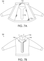
- FIGs. 7A-9 illustrate some example configurations for the fluid-filled bladder described herein along with some example zonal locations.
- FIG. 7A illustrates an upper-body garment 700 in the form of a jacket. The upper-body garment 700 is shown in an open state such that the inner-facing surface of the upper-body garment 700 is visible.
- a fluid-filled bladder 710 in a T-shape is shown at a central back area 712 of the upper-body garment 700 where the arms of the T-shape are positioned adjacent to a neck opening of the upper-body garment 700 and the stem of T-shape is located adjacent to a waist opening of the upper-body garment 700.
- This location may be based on heat and/or sweat maps that indicate that the central back area 712 is a high heat and/or sweat-producing area of the human body.
- the fluid-filled bladder 710 may be positioned between two textile layers as shown in FIGs. 6A and 6B where the innermost-facing textile layer 714 includes, for example, a mesh construction as indicated by the cross-hatch shading.
- different portions of the fluid-filled bladder may change shape independently of other portions of the fluid-filled bladder 710.
- the arms of the fluid-filled bladder 710 may change from a shape where both surfaces of the fluid-filled bladder 710 are relatively planar with respect to each other to a shape where the surface of the fluid-filled bladder in contact with moisture assumes a convex shape while the stem of the fluid-filled bladder does not change shape. This may be due to differential perspiration production along the central back area of the wearer.
- FIG. 7B illustrates a back view of an outer-facing surface of the upper-body garment 700.
- Precipitation 716 is shown hitting the shoulders and upper-back area of the upper-body garment 700.
- the precipitation 716 may cause the surface of the fluid-filled bladder 710 that faces toward the external environment to transition from a relatively planar shape to a convex shape.
- the convex shape may act to redirect the precipitation 716 along the sides of the upper-body garment 700 as shown by the arrows 718.
- the material forming an outermost-facing surface or layer of the upper-body garment 700 may comprise a mesh construction or may possess a moisture-wicking characteristic to facilitate the movement of the precipitation 716 to the surface of the fluid-filled bladder 710.
- FIG. 8 illustrates another example upper-body garment 800 in an open state.
- a fluid-filled bladder 810 is positioned at a central back area 812 of the upper-body garment 800 and, in example aspects, is positioned between two textile layers where the innermost-facing textile layer 814 includes, for example, a mesh construction as indicated by the cross-hatch shading.
- the fluid-filled bladder 810 has a shape configuration including a number of bladder sections, such as bladder sections 810a and 810b connected by a number of conduit sections such as conduit sections 810c and 810d.
- the conduit sections 810c and 810d may act as a conduit for fluid contained within the fluid-filled bladder 810 to move from one bladder section such as the bladder section 810a to another bladder section such as the bladder section 810b in response to a change in shape of a particular bladder section. Similar to the fluid-filled bladder 710, different bladder sections of the fluid-filled bladder 810 may change from a first shape to a second shape independently of other bladder sections of the fluid-filled bladder 810. Again, this may be due to differential perspiration production along the central back area of the wearer.
- FIG. 9 illustrates yet another example upper-body garment 900 in an open state.
- a plurality of distinct and separate fluid-filled bladders 910 are positioned at a central back area 912 and, in example aspects, are positioned between two textile layers where the innermost-facing textile layer 914 may include, for example, a mesh construction. Based on differential perspiration production of the wearer, different fluid-filled bladders of the plurality of fluid-filled bladders 910 may change shape to produce stand-off in areas of sweat production while other fluid-filled bladders of the plurality of fluid-filled bladders 910 remain generally flat.
- fluid-filled bladders 710, 810, and 910 are illustrative, and it is contemplated that the fluid-filled bladders may have other shape configurations and may positioned at other locations on the garment to optimize stand-off where needed.
- FIG. 10 illustrates an article of headwear 1000 in the form of a hat.
- a series of fluid-filled bladders 1010 are positioned around a lower edge of the crown of the article of headwear 1000.
- the fluid-filled bladders 1010 may change from a relatively flat shape to a convex or partially convex shape to produce stand-off between the article of headwear 1000 and the wearer's head thereby improving wearer comfort.
- FIG. 11 illustrate an article of footwear 1100 in the form of a shoe.
- One or more fluid-filled bladders 1110 are positioned in a tongue area of the upper of the article of footwear 1100.
- the fluid-filled bladders 1110 may transition to a more convex shape and create stand-off in this area to improve wearer comfort and facilitate air circulation within the article of footwear 1100.
- the location of the fluid-filled bladders 1110 is illustrative, and other locations on the article of footwear 1100 are contemplated herein.
- FIG. 12 illustrates a lower-body garment 1200 in the form of a pant.
- the lower-body garment 1200 may be in the form of a short, a tight, a capri, and the like.
- the lower-body garment 1200 includes fluid-filled bladders 1210 positioned at an anterior thigh area of the leg portions of the lower-body garment 1200. This location is illustrative, and it is contemplated that the fluid-filled bladders 1210 may be positioned at other locations on the lower-body garment 1200 based on, for example, heat and/or sweat maps and/or rain contact maps of the human body. In response to perspiration produced by the wearer, the fluid-filled bladders 1210 transition from a first shape to a second shape to produce stand-off in areas where they are located.
- FIG. 13 illustrates a flow diagram of an example method of manufacturing a garment having a fluid-filled bladder and is referenced generally by the numeral 1300.
- a fluid-filled bladder such as the fluid-filled bladder 100
- the first and second textile layers may include the first and second textile layers 610 and 612 of FIGs. 6A and 6B .
- the second textile layer forms an innermost-facing surface of the garment.
- the fluid-filled bladder is at least partially formed of a film material that undergoes a change in dimension in at least a z-direction when exposed to moisture to cause the fluid-filled bladder to transition from a first, relatively flat shape to a second shape.
- the surface of the fluid-filled bladder that has been exposed to moisture transitions to a convex shape that produces stand-off between the first and second textile layers and a wearer's body surface.
Landscapes
- Engineering & Computer Science (AREA)
- Textile Engineering (AREA)
- Health & Medical Sciences (AREA)
- General Health & Medical Sciences (AREA)
- Physical Education & Sports Medicine (AREA)
- Physics & Mathematics (AREA)
- Thermal Sciences (AREA)
- Environmental & Geological Engineering (AREA)
- Life Sciences & Earth Sciences (AREA)
- Wood Science & Technology (AREA)
- Professional, Industrial, Or Sporting Protective Garments (AREA)
- Laminated Bodies (AREA)
Claims (15)
- Kleidungsstück, umfassend: eine Textilschicht (510, 610, 612); und eine fluidgefüllte Blase (100), die an der Textilschicht (510, 610, 612) befestigt ist, und dadurch gekennzeichnet, dass
die fluidgefüllte Blase (100) umfasst: eine innere Schicht (210), die einem Innenraum der fluidgefüllten Blase (100) zugewandt ist, und eine äußere Schicht (212), die auf die innere Schicht (210) laminiert und außerhalb der inneren Schicht (210) angeordnet ist, wobei die äußere Schicht (212) aus einem Folienmaterial gebildet ist, das eine Dimensionsänderung in mindestens einer z-Richtung erfährt, wenn es Feuchtigkeit (118) ausgesetzt wird, um zu bewirken, dass die fluidgefüllte Blase (100) von einer ersten Form in eine zweite Form übergeht, wobei die z-Richtung im Allgemeinen orthogonal zu der Oberflächenebene der fluidgefüllten Blase (100) ist. - Kleidungsstück nach Anspruch 1, wobei sich die erste Form in Bezug auf eine Oberflächenebene der Textilschicht (510, 610, 612) um eine erste Distanz in der z-Richtung erstreckt, wobei sich die zweite Form in Bezug auf die Oberflächenebene der Textilschicht (510, 610, 612) um eine zweite Distanz in der z-Richtung erstreckt, und wobei die zweite Distanz größer als die erste Distanz ist; und
wobei die zweite Distanz optional von etwa 3,0 cm bis etwa 4,0 cm beträgt. - Kleidungsstück nach einem der Ansprüche 1 bis 2, wobei das Folienmaterial der äußeren Schicht (212) der fluidgefüllten Blase (100) ein thermoplastisches Polyesterelastomer umfasst.
- Kleidungsstück nach einem der Ansprüche 1 bis 3, wobei die fluidgefüllte Blase (100) weiter eine Haftfilmschicht (214) umfasst, die zwischen der äußeren Schicht (212) und der inneren Schicht (210) angeordnet ist, wobei die Haftfilmschicht (214) verwendet wird, um die äußere Schicht (212) an die innere Schicht (210) anzuhaften.
- Kleidungsstück nach einem der Ansprüche 1 bis 4, wobei die Textilschicht (610, 612) eine erste Textilschicht (610) und eine zweite Textilschicht (612), die neben der ersten Textilschicht (610) angeordnet ist, um einen Raum dazwischen zu bilden, enthält;wobei die fluidgefüllte Blase (100) optional in dem Raum zwischen der ersten Textilschicht (610) und der zweiten Textilschicht (612) befestigt ist; undwobei die zweite Textilschicht (612) optional zumindest teilweise eine innerst-zugewandte Fläche des Kleidungsstücks bildet.
- Kleidungsstück, umfassend: eine erste Textilschicht (610); und eine zweite Textilschicht (612), die neben der ersten Textilschicht (610) angeordnet ist, um einen Raum dazwischen zu bilden, wobei die zweite Textilschicht (612) zumindest teilweise eine innerst-zugewandte Fläche des Kleidungsstücks bildet; dadurch gekennzeichnet, dass das Kleidungsstück weiter eine fluidgefüllte Blase (100) umfasst, die in dem Raum zwischen der ersten Textilschicht (610) und der zweiten Textilschicht (612) befestigt ist, wobei die fluidgefüllte Blase (100) eine Dimensionsänderung in mindestens einer z-Richtung erfährt, wenn sie Feuchtigkeit (118) ausgesetzt wird, um zu bewirken, dass die fluidgefüllte Blase (100) von einer ersten Form in eine zweite Form übergeht, wobei die z-Richtung im Allgemeinen orthogonal zu der Oberflächenebene der fluidgefüllten Blase (100) ist.
- Kleidungsstück nach Anspruch 6, wobei die fluidgefüllte Blase (100) umfasst:eine innere Schicht (210, 310), die einem Innenraum der fluidgefüllten Blase (100) zugewandt ist, und eine äußere Schicht (212, 312), die auf die innere Schicht (210, 310) laminiert und außerhalb der inneren Schicht (210, 310) angeordnet ist;wobei die äußere Schicht (212) optional die Dimensionsänderung in der z-Richtung erfährt, wenn sie Feuchtigkeit (118) ausgesetzt wird.
- Kleidungsstück nach Anspruch 7, wobei die innere Schicht (210, 310) die Dimensionsänderung in der z-Richtung nicht erfährt, wenn sie Feuchtigkeit (118) ausgesetzt wird.
- Kleidungsstück nach einem der Ansprüche 7 bis 8, wobei die äußere Schicht (212) aus einem thermoplastischen Polyesterelastomer gebildet ist.
- Kleidungsstück nach einem der Ansprüche 1 bis 3 oder Kleidungsstück nach einem der Ansprüche 7 bis 9, wobei die innere Schicht (210) aus einem Polyurethanmaterial gebildet ist.
- Verfahren (1300) zur Herstellung eines Kleidungsstücks mit einer fluidgefüllten Blase (100), wobei das Verfahren umfasst: Befestigen (1310) der fluidgefüllten Blase (100) in einem Raum zwischen einer ersten Textilschicht (610) und einer zweiten Textilschicht (612), die das Kleidungsstück bilden, wobei die zweite Textilschicht (612) zumindest teilweise eine innerst-zugewandte Fläche des Kleidungsstücks bildet, und wobei die fluidgefüllte Blase (100) eine Dimensionsänderung in mindestens einer z-Richtung erfährt, wenn sie Feuchtigkeit (118) ausgesetzt wird, um zu bewirken, dass die fluidgefüllte Blase (100) von einer ersten Form in eine zweite Form übergeht, wobei die z-Richtung im Allgemeinen orthogonal zu der Oberflächenebene der fluidgefüllten Blase (100) ist.
- Verfahren (1300) zur Herstellung des Kleidungsstücks mit der fluidgefüllten Blase (100) nach Anspruch 11, wobei die zweite Textilschicht (612) ein Netztextil ist.
- Verfahren (1300) zur Herstellung des Kleidungsstücks mit der fluidgefüllten Blase (100) nach einem der Ansprüche 11 bis 12, wobei die zweite Textilschicht (612) feuchtigkeitsableitende Eigenschaften aufweist.
- Verfahren (1300) zur Herstellung des Kleidungsstücks mit der fluidgefüllten Blase (100) nach einem der Ansprüche 11 bis 13, wobei die fluidgefüllte Blase (100) umfasst: eine innere Schicht (210), die einem Innenraum der fluidgefüllten Blase (100) zugewandt ist, und eine äußere Schicht (212), die auf die innere Schicht (210) laminiert und außerhalb der inneren Schicht (210) angeordnet ist, wobei die äußere Schicht (212) die Dimensionsänderung in der z-Richtung erfährt, wenn sie Feuchtigkeit (118) ausgesetzt wird.
- Verfahren (1300) zur Herstellung des Kleidungsstücks mit der fluidgefüllten Blase (100) nach einem der Ansprüche 11 bis 14, wobei sich die erste Form in Bezug auf eine Oberflächenebene mindestens der zweiten Textilschicht (612) um eine erste Distanz in der z-Richtung erstreckt, wobei sich die zweite Form in Bezug auf die Oberflächenebene der zweiten Textilschicht (612) um eine zweite Distanz in der z-Richtung erstreckt, und wobei die zweite Distanz größer als die erste Distanz ist.
Priority Applications (1)
| Application Number | Priority Date | Filing Date | Title |
|---|---|---|---|
| EP24188800.7A EP4420550A3 (de) | 2020-05-19 | 2021-04-15 | Kleidungsstück mit adaptiven abstandseigenschaften |
Applications Claiming Priority (3)
| Application Number | Priority Date | Filing Date | Title |
|---|---|---|---|
| US202063027042P | 2020-05-19 | 2020-05-19 | |
| US17/225,638 US11785999B2 (en) | 2020-05-19 | 2021-04-08 | Garment with adaptive stand-off features |
| PCT/US2021/027488 WO2021236265A1 (en) | 2020-05-19 | 2021-04-15 | Garment with adaptive stand-off features |
Related Child Applications (1)
| Application Number | Title | Priority Date | Filing Date |
|---|---|---|---|
| EP24188800.7A Division EP4420550A3 (de) | 2020-05-19 | 2021-04-15 | Kleidungsstück mit adaptiven abstandseigenschaften |
Publications (2)
| Publication Number | Publication Date |
|---|---|
| EP4152987A1 EP4152987A1 (de) | 2023-03-29 |
| EP4152987B1 true EP4152987B1 (de) | 2024-07-17 |
Family
ID=78609255
Family Applications (2)
| Application Number | Title | Priority Date | Filing Date |
|---|---|---|---|
| EP24188800.7A Pending EP4420550A3 (de) | 2020-05-19 | 2021-04-15 | Kleidungsstück mit adaptiven abstandseigenschaften |
| EP21723582.9A Active EP4152987B1 (de) | 2020-05-19 | 2021-04-15 | Kleidungsstück mit adaptiven abstandseigenschaften |
Family Applications Before (1)
| Application Number | Title | Priority Date | Filing Date |
|---|---|---|---|
| EP24188800.7A Pending EP4420550A3 (de) | 2020-05-19 | 2021-04-15 | Kleidungsstück mit adaptiven abstandseigenschaften |
Country Status (6)
| Country | Link |
|---|---|
| US (2) | US11785999B2 (de) |
| EP (2) | EP4420550A3 (de) |
| JP (1) | JP2023526930A (de) |
| KR (1) | KR102719795B1 (de) |
| CN (2) | CN115666303B (de) |
| WO (1) | WO2021236265A1 (de) |
Families Citing this family (2)
| Publication number | Priority date | Publication date | Assignee | Title |
|---|---|---|---|---|
| US11785999B2 (en) * | 2020-05-19 | 2023-10-17 | Nike, Inc. | Garment with adaptive stand-off features |
| US20260033575A1 (en) * | 2024-07-31 | 2026-02-05 | Nike, Inc. | Laminates, Bladders, and Garments Including Laminates and Bladders |
Citations (1)
| Publication number | Priority date | Publication date | Assignee | Title |
|---|---|---|---|---|
| AT9009U1 (de) * | 2006-02-01 | 2007-04-15 | Emcools Emergency Medical Cool | Einrichtung zum kühlen des körpers von personen oder dergl. |
Family Cites Families (18)
| Publication number | Priority date | Publication date | Assignee | Title |
|---|---|---|---|---|
| JP3185796B2 (ja) * | 1998-09-21 | 2001-07-11 | 株式会社ファルコンテクノロジー | 2層構造の布、および衣服 |
| US20050204454A1 (en) * | 2004-03-18 | 2005-09-22 | Wu Chin W | Wetsuit and wetsuit fabric |
| JP2006264309A (ja) * | 2005-02-23 | 2006-10-05 | Teijin Fibers Ltd | 吸水により立体的に構造変化する多層構造体および繊維製品 |
| US20080254263A1 (en) | 2005-02-23 | 2008-10-16 | Teijin Fibers Limited | Composite Fabric Material Exhibiting Three-Dimensional Structural Change Upon Water Absorption, and Textile Products |
| US7401418B2 (en) * | 2005-08-17 | 2008-07-22 | Nike, Inc. | Article of footwear having midsole with support pillars and method of manufacturing same |
| US20130078415A1 (en) * | 2006-06-09 | 2013-03-28 | Mmi-Ipco, Llc | Temperature Responsive Smart Textile |
| US8187984B2 (en) * | 2006-06-09 | 2012-05-29 | Malden Mills Industries, Inc. | Temperature responsive smart textile |
| JP2008057100A (ja) * | 2006-08-29 | 2008-03-13 | Mmi-Ipco Llc | 感温性且つ感湿性のスマートテキスタイル |
| JP5275657B2 (ja) * | 2008-03-27 | 2013-08-28 | 帝人フロンティア株式会社 | 吸湿により厚さが減少する織編物および繊維製品 |
| JP2011094272A (ja) * | 2009-11-02 | 2011-05-12 | Utax:Kk | 機能性生地およびその機能性生地を用いた衣類 |
| KR20140020872A (ko) * | 2011-01-28 | 2014-02-19 | 더블유.엘.고어 앤드 어소시에이츠 게엠베하 | 적응적 단열을 제공하는 라미나 구조체 |
| JP2016168770A (ja) * | 2015-03-13 | 2016-09-23 | コニカミノルタ株式会社 | ウインドウフィルム |
| US10271580B2 (en) * | 2015-09-14 | 2019-04-30 | Nike, Inc. | Apparel item configured for reduced cling perception |
| US20170106622A1 (en) * | 2015-10-14 | 2017-04-20 | Robert J. Bonin | Thermoregulatory impact resistant material |
| US10264834B2 (en) * | 2016-03-25 | 2019-04-23 | Nike, Inc. | Foam nodes for creating stand off on apparel items |
| CN109648932B (zh) * | 2019-01-18 | 2020-06-09 | 安徽工程大学 | 一种高效速干面料 |
| US12550959B2 (en) * | 2019-08-12 | 2026-02-17 | Nike, Inc. | Apparel with adaptive fit |
| US11785999B2 (en) * | 2020-05-19 | 2023-10-17 | Nike, Inc. | Garment with adaptive stand-off features |
-
2021
- 2021-04-08 US US17/225,638 patent/US11785999B2/en active Active
- 2021-04-15 CN CN202180037437.0A patent/CN115666303B/zh active Active
- 2021-04-15 EP EP24188800.7A patent/EP4420550A3/de active Pending
- 2021-04-15 EP EP21723582.9A patent/EP4152987B1/de active Active
- 2021-04-15 WO PCT/US2021/027488 patent/WO2021236265A1/en not_active Ceased
- 2021-04-15 KR KR1020227043387A patent/KR102719795B1/ko active Active
- 2021-04-15 JP JP2022570669A patent/JP2023526930A/ja active Pending
- 2021-04-15 CN CN202511638710.1A patent/CN121465324A/zh active Pending
-
2023
- 2023-09-11 US US18/244,499 patent/US12532929B2/en active Active
Patent Citations (1)
| Publication number | Priority date | Publication date | Assignee | Title |
|---|---|---|---|---|
| AT9009U1 (de) * | 2006-02-01 | 2007-04-15 | Emcools Emergency Medical Cool | Einrichtung zum kühlen des körpers von personen oder dergl. |
Also Published As
| Publication number | Publication date |
|---|---|
| EP4420550A2 (de) | 2024-08-28 |
| US20210361010A1 (en) | 2021-11-25 |
| CN115666303A (zh) | 2023-01-31 |
| CA3182680A1 (en) | 2021-11-25 |
| CN115666303B (zh) | 2025-11-18 |
| US12532929B2 (en) | 2026-01-27 |
| EP4420550A3 (de) | 2024-12-11 |
| EP4152987A1 (de) | 2023-03-29 |
| KR102719795B1 (ko) | 2024-10-18 |
| CN121465324A (zh) | 2026-02-06 |
| JP2023526930A (ja) | 2023-06-26 |
| US11785999B2 (en) | 2023-10-17 |
| KR20230006020A (ko) | 2023-01-10 |
| US20230413933A1 (en) | 2023-12-28 |
| WO2021236265A1 (en) | 2021-11-25 |
Similar Documents
| Publication | Publication Date | Title |
|---|---|---|
| US11737503B2 (en) | Insulated garment | |
| US11229250B2 (en) | Cold weather vented garment | |
| US12532929B2 (en) | Garment with adaptive stand-off features | |
| US20250295189A1 (en) | Apparel with cling reduction features | |
| US20230210204A1 (en) | Dynamic vent structure for apparel | |
| CA3182680C (en) | Garment with adaptive stand-off features | |
| JP2023001734A (ja) | 積層布地製造方法 | |
| HK40069533A (en) | Apparel with cling reduction features | |
| WO2023133279A1 (en) | Dynamic vent structure for apparel |
Legal Events
| Date | Code | Title | Description |
|---|---|---|---|
| STAA | Information on the status of an ep patent application or granted ep patent |
Free format text: STATUS: UNKNOWN |
|
| STAA | Information on the status of an ep patent application or granted ep patent |
Free format text: STATUS: THE INTERNATIONAL PUBLICATION HAS BEEN MADE |
|
| PUAI | Public reference made under article 153(3) epc to a published international application that has entered the european phase |
Free format text: ORIGINAL CODE: 0009012 |
|
| STAA | Information on the status of an ep patent application or granted ep patent |
Free format text: STATUS: REQUEST FOR EXAMINATION WAS MADE |
|
| 17P | Request for examination filed |
Effective date: 20221027 |
|
| AK | Designated contracting states |
Kind code of ref document: A1 Designated state(s): AL AT BE BG CH CY CZ DE DK EE ES FI FR GB GR HR HU IE IS IT LI LT LU LV MC MK MT NL NO PL PT RO RS SE SI SK SM TR |
|
| P01 | Opt-out of the competence of the unified patent court (upc) registered |
Effective date: 20230515 |
|
| DAV | Request for validation of the european patent (deleted) | ||
| DAX | Request for extension of the european patent (deleted) | ||
| GRAP | Despatch of communication of intention to grant a patent |
Free format text: ORIGINAL CODE: EPIDOSNIGR1 |
|
| STAA | Information on the status of an ep patent application or granted ep patent |
Free format text: STATUS: GRANT OF PATENT IS INTENDED |
|
| INTG | Intention to grant announced |
Effective date: 20240206 |
|
| GRAS | Grant fee paid |
Free format text: ORIGINAL CODE: EPIDOSNIGR3 |
|
| GRAA | (expected) grant |
Free format text: ORIGINAL CODE: 0009210 |
|
| STAA | Information on the status of an ep patent application or granted ep patent |
Free format text: STATUS: THE PATENT HAS BEEN GRANTED |
|
| AK | Designated contracting states |
Kind code of ref document: B1 Designated state(s): AL AT BE BG CH CY CZ DE DK EE ES FI FR GB GR HR HU IE IS IT LI LT LU LV MC MK MT NL NO PL PT RO RS SE SI SK SM TR |
|
| REG | Reference to a national code |
Ref country code: CH Ref legal event code: EP |
|
| REG | Reference to a national code |
Ref country code: DE Ref legal event code: R096 Ref document number: 602021015840 Country of ref document: DE |
|
| REG | Reference to a national code |
Ref country code: IE Ref legal event code: FG4D |
|
| REG | Reference to a national code |
Ref country code: LT Ref legal event code: MG9D |
|
| REG | Reference to a national code |
Ref country code: NL Ref legal event code: MP Effective date: 20240717 |
|
| PG25 | Lapsed in a contracting state [announced via postgrant information from national office to epo] |
Ref country code: PT Free format text: LAPSE BECAUSE OF FAILURE TO SUBMIT A TRANSLATION OF THE DESCRIPTION OR TO PAY THE FEE WITHIN THE PRESCRIBED TIME-LIMIT Effective date: 20241118 |
|
| REG | Reference to a national code |
Ref country code: AT Ref legal event code: MK05 Ref document number: 1703265 Country of ref document: AT Kind code of ref document: T Effective date: 20240717 |
|
| PG25 | Lapsed in a contracting state [announced via postgrant information from national office to epo] |
Ref country code: NL Free format text: LAPSE BECAUSE OF FAILURE TO SUBMIT A TRANSLATION OF THE DESCRIPTION OR TO PAY THE FEE WITHIN THE PRESCRIBED TIME-LIMIT Effective date: 20240717 |
|
| PG25 | Lapsed in a contracting state [announced via postgrant information from national office to epo] |
Ref country code: PT Free format text: LAPSE BECAUSE OF FAILURE TO SUBMIT A TRANSLATION OF THE DESCRIPTION OR TO PAY THE FEE WITHIN THE PRESCRIBED TIME-LIMIT Effective date: 20241118 Ref country code: NL Free format text: LAPSE BECAUSE OF FAILURE TO SUBMIT A TRANSLATION OF THE DESCRIPTION OR TO PAY THE FEE WITHIN THE PRESCRIBED TIME-LIMIT Effective date: 20240717 |
|
| PG25 | Lapsed in a contracting state [announced via postgrant information from national office to epo] |
Ref country code: NO Free format text: LAPSE BECAUSE OF FAILURE TO SUBMIT A TRANSLATION OF THE DESCRIPTION OR TO PAY THE FEE WITHIN THE PRESCRIBED TIME-LIMIT Effective date: 20241017 |
|
| PG25 | Lapsed in a contracting state [announced via postgrant information from national office to epo] |
Ref country code: GR Free format text: LAPSE BECAUSE OF FAILURE TO SUBMIT A TRANSLATION OF THE DESCRIPTION OR TO PAY THE FEE WITHIN THE PRESCRIBED TIME-LIMIT Effective date: 20241018 Ref country code: FI Free format text: LAPSE BECAUSE OF FAILURE TO SUBMIT A TRANSLATION OF THE DESCRIPTION OR TO PAY THE FEE WITHIN THE PRESCRIBED TIME-LIMIT Effective date: 20240717 Ref country code: PL Free format text: LAPSE BECAUSE OF FAILURE TO SUBMIT A TRANSLATION OF THE DESCRIPTION OR TO PAY THE FEE WITHIN THE PRESCRIBED TIME-LIMIT Effective date: 20240717 |
|
| PG25 | Lapsed in a contracting state [announced via postgrant information from national office to epo] |
Ref country code: BG Free format text: LAPSE BECAUSE OF FAILURE TO SUBMIT A TRANSLATION OF THE DESCRIPTION OR TO PAY THE FEE WITHIN THE PRESCRIBED TIME-LIMIT Effective date: 20240717 |
|
| PG25 | Lapsed in a contracting state [announced via postgrant information from national office to epo] |
Ref country code: LV Free format text: LAPSE BECAUSE OF FAILURE TO SUBMIT A TRANSLATION OF THE DESCRIPTION OR TO PAY THE FEE WITHIN THE PRESCRIBED TIME-LIMIT Effective date: 20240717 |
|
| PG25 | Lapsed in a contracting state [announced via postgrant information from national office to epo] |
Ref country code: IS Free format text: LAPSE BECAUSE OF FAILURE TO SUBMIT A TRANSLATION OF THE DESCRIPTION OR TO PAY THE FEE WITHIN THE PRESCRIBED TIME-LIMIT Effective date: 20241117 Ref country code: AT Free format text: LAPSE BECAUSE OF FAILURE TO SUBMIT A TRANSLATION OF THE DESCRIPTION OR TO PAY THE FEE WITHIN THE PRESCRIBED TIME-LIMIT Effective date: 20240717 |
|
| PG25 | Lapsed in a contracting state [announced via postgrant information from national office to epo] |
Ref country code: HR Free format text: LAPSE BECAUSE OF FAILURE TO SUBMIT A TRANSLATION OF THE DESCRIPTION OR TO PAY THE FEE WITHIN THE PRESCRIBED TIME-LIMIT Effective date: 20240717 |
|
| PG25 | Lapsed in a contracting state [announced via postgrant information from national office to epo] |
Ref country code: ES Free format text: LAPSE BECAUSE OF FAILURE TO SUBMIT A TRANSLATION OF THE DESCRIPTION OR TO PAY THE FEE WITHIN THE PRESCRIBED TIME-LIMIT Effective date: 20240717 Ref country code: RS Free format text: LAPSE BECAUSE OF FAILURE TO SUBMIT A TRANSLATION OF THE DESCRIPTION OR TO PAY THE FEE WITHIN THE PRESCRIBED TIME-LIMIT Effective date: 20241017 |
|
| PG25 | Lapsed in a contracting state [announced via postgrant information from national office to epo] |
Ref country code: RS Free format text: LAPSE BECAUSE OF FAILURE TO SUBMIT A TRANSLATION OF THE DESCRIPTION OR TO PAY THE FEE WITHIN THE PRESCRIBED TIME-LIMIT Effective date: 20241017 Ref country code: PL Free format text: LAPSE BECAUSE OF FAILURE TO SUBMIT A TRANSLATION OF THE DESCRIPTION OR TO PAY THE FEE WITHIN THE PRESCRIBED TIME-LIMIT Effective date: 20240717 Ref country code: NO Free format text: LAPSE BECAUSE OF FAILURE TO SUBMIT A TRANSLATION OF THE DESCRIPTION OR TO PAY THE FEE WITHIN THE PRESCRIBED TIME-LIMIT Effective date: 20241017 Ref country code: LV Free format text: LAPSE BECAUSE OF FAILURE TO SUBMIT A TRANSLATION OF THE DESCRIPTION OR TO PAY THE FEE WITHIN THE PRESCRIBED TIME-LIMIT Effective date: 20240717 Ref country code: IS Free format text: LAPSE BECAUSE OF FAILURE TO SUBMIT A TRANSLATION OF THE DESCRIPTION OR TO PAY THE FEE WITHIN THE PRESCRIBED TIME-LIMIT Effective date: 20241117 Ref country code: HR Free format text: LAPSE BECAUSE OF FAILURE TO SUBMIT A TRANSLATION OF THE DESCRIPTION OR TO PAY THE FEE WITHIN THE PRESCRIBED TIME-LIMIT Effective date: 20240717 Ref country code: GR Free format text: LAPSE BECAUSE OF FAILURE TO SUBMIT A TRANSLATION OF THE DESCRIPTION OR TO PAY THE FEE WITHIN THE PRESCRIBED TIME-LIMIT Effective date: 20241018 Ref country code: FI Free format text: LAPSE BECAUSE OF FAILURE TO SUBMIT A TRANSLATION OF THE DESCRIPTION OR TO PAY THE FEE WITHIN THE PRESCRIBED TIME-LIMIT Effective date: 20240717 Ref country code: ES Free format text: LAPSE BECAUSE OF FAILURE TO SUBMIT A TRANSLATION OF THE DESCRIPTION OR TO PAY THE FEE WITHIN THE PRESCRIBED TIME-LIMIT Effective date: 20240717 Ref country code: BG Free format text: LAPSE BECAUSE OF FAILURE TO SUBMIT A TRANSLATION OF THE DESCRIPTION OR TO PAY THE FEE WITHIN THE PRESCRIBED TIME-LIMIT Effective date: 20240717 Ref country code: AT Free format text: LAPSE BECAUSE OF FAILURE TO SUBMIT A TRANSLATION OF THE DESCRIPTION OR TO PAY THE FEE WITHIN THE PRESCRIBED TIME-LIMIT Effective date: 20240717 |
|
| PG25 | Lapsed in a contracting state [announced via postgrant information from national office to epo] |
Ref country code: DK Free format text: LAPSE BECAUSE OF FAILURE TO SUBMIT A TRANSLATION OF THE DESCRIPTION OR TO PAY THE FEE WITHIN THE PRESCRIBED TIME-LIMIT Effective date: 20240717 Ref country code: RO Free format text: LAPSE BECAUSE OF FAILURE TO SUBMIT A TRANSLATION OF THE DESCRIPTION OR TO PAY THE FEE WITHIN THE PRESCRIBED TIME-LIMIT Effective date: 20240717 Ref country code: SM Free format text: LAPSE BECAUSE OF FAILURE TO SUBMIT A TRANSLATION OF THE DESCRIPTION OR TO PAY THE FEE WITHIN THE PRESCRIBED TIME-LIMIT Effective date: 20240717 |
|
| REG | Reference to a national code |
Ref country code: DE Ref legal event code: R097 Ref document number: 602021015840 Country of ref document: DE |
|
| PG25 | Lapsed in a contracting state [announced via postgrant information from national office to epo] |
Ref country code: EE Free format text: LAPSE BECAUSE OF FAILURE TO SUBMIT A TRANSLATION OF THE DESCRIPTION OR TO PAY THE FEE WITHIN THE PRESCRIBED TIME-LIMIT Effective date: 20240717 |
|
| PG25 | Lapsed in a contracting state [announced via postgrant information from national office to epo] |
Ref country code: CZ Free format text: LAPSE BECAUSE OF FAILURE TO SUBMIT A TRANSLATION OF THE DESCRIPTION OR TO PAY THE FEE WITHIN THE PRESCRIBED TIME-LIMIT Effective date: 20240717 |
|
| PG25 | Lapsed in a contracting state [announced via postgrant information from national office to epo] |
Ref country code: SK Free format text: LAPSE BECAUSE OF FAILURE TO SUBMIT A TRANSLATION OF THE DESCRIPTION OR TO PAY THE FEE WITHIN THE PRESCRIBED TIME-LIMIT Effective date: 20240717 |
|
| PLBE | No opposition filed within time limit |
Free format text: ORIGINAL CODE: 0009261 |
|
| STAA | Information on the status of an ep patent application or granted ep patent |
Free format text: STATUS: NO OPPOSITION FILED WITHIN TIME LIMIT |
|
| 26N | No opposition filed |
Effective date: 20250422 |
|
| PGFP | Annual fee paid to national office [announced via postgrant information from national office to epo] |
Ref country code: DE Payment date: 20250218 Year of fee payment: 5 |
|
| PG25 | Lapsed in a contracting state [announced via postgrant information from national office to epo] |
Ref country code: SE Free format text: LAPSE BECAUSE OF FAILURE TO SUBMIT A TRANSLATION OF THE DESCRIPTION OR TO PAY THE FEE WITHIN THE PRESCRIBED TIME-LIMIT Effective date: 20240717 |
|
| REG | Reference to a national code |
Ref country code: CH Ref legal event code: H13 Free format text: ST27 STATUS EVENT CODE: U-0-0-H10-H13 (AS PROVIDED BY THE NATIONAL OFFICE) Effective date: 20251125 |
|
| PG25 | Lapsed in a contracting state [announced via postgrant information from national office to epo] |
Ref country code: LU Free format text: LAPSE BECAUSE OF NON-PAYMENT OF DUE FEES Effective date: 20250415 |
|
| PG25 | Lapsed in a contracting state [announced via postgrant information from national office to epo] |
Ref country code: MC Free format text: LAPSE BECAUSE OF FAILURE TO SUBMIT A TRANSLATION OF THE DESCRIPTION OR TO PAY THE FEE WITHIN THE PRESCRIBED TIME-LIMIT Effective date: 20240717 |
|
| REG | Reference to a national code |
Ref country code: BE Ref legal event code: MM Effective date: 20250430 |
|
| PG25 | Lapsed in a contracting state [announced via postgrant information from national office to epo] |
Ref country code: BE Free format text: LAPSE BECAUSE OF NON-PAYMENT OF DUE FEES Effective date: 20250430 |
|
| PG25 | Lapsed in a contracting state [announced via postgrant information from national office to epo] |
Ref country code: CH Free format text: LAPSE BECAUSE OF NON-PAYMENT OF DUE FEES Effective date: 20250430 |
|
| PG25 | Lapsed in a contracting state [announced via postgrant information from national office to epo] |
Ref country code: IT Free format text: LAPSE BECAUSE OF FAILURE TO SUBMIT A TRANSLATION OF THE DESCRIPTION OR TO PAY THE FEE WITHIN THE PRESCRIBED TIME-LIMIT Effective date: 20240717 |
|
| PGFP | Annual fee paid to national office [announced via postgrant information from national office to epo] |
Ref country code: GB Payment date: 20260219 Year of fee payment: 6 |
|
| PG25 | Lapsed in a contracting state [announced via postgrant information from national office to epo] |
Ref country code: IE Free format text: LAPSE BECAUSE OF NON-PAYMENT OF DUE FEES Effective date: 20250415 |
|
| PGFP | Annual fee paid to national office [announced via postgrant information from national office to epo] |
Ref country code: FR Payment date: 20260209 Year of fee payment: 6 |