EP4152452B1 - Dispositif de positionnement, dispositif d'empilement et procédé d'empilement pour composants d'un empilement d'éléments de batterie ou de piles à combustible - Google Patents
Dispositif de positionnement, dispositif d'empilement et procédé d'empilement pour composants d'un empilement d'éléments de batterie ou de piles à combustible Download PDFInfo
- Publication number
- EP4152452B1 EP4152452B1 EP21197541.2A EP21197541A EP4152452B1 EP 4152452 B1 EP4152452 B1 EP 4152452B1 EP 21197541 A EP21197541 A EP 21197541A EP 4152452 B1 EP4152452 B1 EP 4152452B1
- Authority
- EP
- European Patent Office
- Prior art keywords
- jaw
- positioning
- vibrating
- contact surface
- cell stack
- Prior art date
- Legal status (The legal status is an assumption and is not a legal conclusion. Google has not performed a legal analysis and makes no representation as to the accuracy of the status listed.)
- Active
Links
Images


Classifications
-
- H—ELECTRICITY
- H01—ELECTRIC ELEMENTS
- H01M—PROCESSES OR MEANS, e.g. BATTERIES, FOR THE DIRECT CONVERSION OF CHEMICAL ENERGY INTO ELECTRICAL ENERGY
- H01M10/00—Secondary cells; Manufacture thereof
- H01M10/04—Construction or manufacture in general
- H01M10/0404—Machines for assembling batteries
-
- B—PERFORMING OPERATIONS; TRANSPORTING
- B65—CONVEYING; PACKING; STORING; HANDLING THIN OR FILAMENTARY MATERIAL
- B65H—HANDLING THIN OR FILAMENTARY MATERIAL, e.g. SHEETS, WEBS, CABLES
- B65H31/00—Pile receivers
- B65H31/04—Pile receivers with movable end support arranged to recede as pile accumulates
- B65H31/08—Pile receivers with movable end support arranged to recede as pile accumulates the articles being piled one above another
- B65H31/10—Pile receivers with movable end support arranged to recede as pile accumulates the articles being piled one above another and applied at the top of the pile
-
- B—PERFORMING OPERATIONS; TRANSPORTING
- B65—CONVEYING; PACKING; STORING; HANDLING THIN OR FILAMENTARY MATERIAL
- B65H—HANDLING THIN OR FILAMENTARY MATERIAL, e.g. SHEETS, WEBS, CABLES
- B65H31/00—Pile receivers
- B65H31/34—Apparatus for squaring-up piled articles
- B65H31/38—Apparatus for vibrating or knocking the pile during piling
-
- H—ELECTRICITY
- H01—ELECTRIC ELEMENTS
- H01M—PROCESSES OR MEANS, e.g. BATTERIES, FOR THE DIRECT CONVERSION OF CHEMICAL ENERGY INTO ELECTRICAL ENERGY
- H01M10/00—Secondary cells; Manufacture thereof
- H01M10/04—Construction or manufacture in general
- H01M10/0463—Cells or batteries with horizontal or inclined electrodes
-
- H—ELECTRICITY
- H01—ELECTRIC ELEMENTS
- H01M—PROCESSES OR MEANS, e.g. BATTERIES, FOR THE DIRECT CONVERSION OF CHEMICAL ENERGY INTO ELECTRICAL ENERGY
- H01M8/00—Fuel cells; Manufacture thereof
- H01M8/24—Grouping of fuel cells, e.g. stacking of fuel cells
- H01M8/2404—Processes or apparatus for grouping fuel cells
-
- Y—GENERAL TAGGING OF NEW TECHNOLOGICAL DEVELOPMENTS; GENERAL TAGGING OF CROSS-SECTIONAL TECHNOLOGIES SPANNING OVER SEVERAL SECTIONS OF THE IPC; TECHNICAL SUBJECTS COVERED BY FORMER USPC CROSS-REFERENCE ART COLLECTIONS [XRACs] AND DIGESTS
- Y02—TECHNOLOGIES OR APPLICATIONS FOR MITIGATION OR ADAPTATION AGAINST CLIMATE CHANGE
- Y02E—REDUCTION OF GREENHOUSE GAS [GHG] EMISSIONS, RELATED TO ENERGY GENERATION, TRANSMISSION OR DISTRIBUTION
- Y02E60/00—Enabling technologies; Technologies with a potential or indirect contribution to GHG emissions mitigation
- Y02E60/30—Hydrogen technology
- Y02E60/50—Fuel cells
-
- Y—GENERAL TAGGING OF NEW TECHNOLOGICAL DEVELOPMENTS; GENERAL TAGGING OF CROSS-SECTIONAL TECHNOLOGIES SPANNING OVER SEVERAL SECTIONS OF THE IPC; TECHNICAL SUBJECTS COVERED BY FORMER USPC CROSS-REFERENCE ART COLLECTIONS [XRACs] AND DIGESTS
- Y02—TECHNOLOGIES OR APPLICATIONS FOR MITIGATION OR ADAPTATION AGAINST CLIMATE CHANGE
- Y02P—CLIMATE CHANGE MITIGATION TECHNOLOGIES IN THE PRODUCTION OR PROCESSING OF GOODS
- Y02P70/00—Climate change mitigation technologies in the production process for final industrial or consumer products
- Y02P70/50—Manufacturing or production processes characterised by the final manufactured product
Definitions
- the invention relates to a positioning device for positioning repeat components of a cell stack for battery or fuel cells that are to be placed on top of one another.
- the invention further relates to a stacking device for forming a cell stack for a battery cell or fuel cell from repeat components that are to be placed on top of one another, with at least one such positioning device.
- the invention relates to a stacking method using such a stacking device.
- the present invention is in the fields of manufacturing battery cell stacks (preferably of the lithium-ion cell type), see [1], and the manufacturing of fuel cell stacks (preferably of the PEMFC type), see [2].
- Preferred embodiments of the invention relate to a system for receiving, positioning and fixing all components required for the construction or manufacture of battery cells, such as lithium-ion battery cells, or fuel cell stacks, such as PEMFC stacks, with a view to production in a large-scale plant.
- the object of the invention is to provide a positioning device with which repeat components of battery or fuel cells can be positioned more reliably and precisely when deposited into a stack at high process speeds in large series.
- the invention provides a stacking device according to claim 1.
- a stacking device with such a positioning device and a stacking method that can be carried out therewith are the subject of the dependent claims.
- the projection-recess formation is a comb structure with grooves formed between teeth, wherein vibrating jaw teeth engage in positioning jaw grooves and positioning jaw teeth engage in vibrating jaw grooves, wherein the abutment surfaces are formed at least partially on the teeth.
- the projection-recess formation can also have a single projection on one of the jaws - positioning and vibrating jaw - which engages in a recess on the other of the jaws - positioning and vibrating jaw.
- a positioning jaw tooth can engage in a vibrating jaw groove.
- a tooth on the vibrating jaw and a tooth on the positioning jaw can also be a tooth on the vibrating jaw and a tooth on the positioning jaw and, complementary to this, a groove on the vibrating jaw and a groove on the positioning jaw.
- the projection-recess formation extends over the entire width of the contact surfaces.
- a first arrangement of a first positioning jaw and a first vibrating jaw and a second arrangement of a second positioning jaw and a second vibrating jaw are arranged on a first Pair of opposite sides of a receptacle for the cell stack.
- a third arrangement of a third positioning jaw and a third vibrating jaw and a fourth arrangement of a fourth positioning jaw and a fourth vibrating jaw are located opposite each other on a second pair of opposite sides of the receptacle for the cell stack.
- the vibration generators of different arrangements can be controlled individually and/or differently.
- the movement can be in opposite directions or in the same direction in pairs or individually inactive.
- a control is designed to control the vibration generators in such a way that the movement of the vibration generators is in opposite directions in pairs or the movement of the vibration generators is in the same direction in pairs or that individual vibration generators are inactive.
- the vibrating jaw is U-shaped in cross section with a first leg on which the vibrating jaw contact surface and the projection-recess formation are formed, and a second leg which is connected to the vibration generator, and a web which engages over a body of the positioning jaw.
- the second leg also has a projection-recess formation.
- the positioning jaw is bevelled or rounded at an upper end region above the positioning jaw contact surface to form an insertion bevel.
- the positioning jaw is rounded at an upper end region of the positioning jaw contact surface so as to be flush with or aligned with the arc path.
- the positioning jaw is block-shaped or strip-shaped.
- the positioning jaw is designed such that the projection-recess formation is formed on a side surface facing a receptacle for receiving the cell stack.
- the positioning jaw extends along a height direction for guiding the edges of the repeat components in the cell stack during height adjustment in the receptacle.
- the vibrating jaw oscillates between a first end position in which the vibrating jaw contact surface and the positioning jaw contact surface are aligned with each other and a second end position in which the vibrating jaw contact surface is at least partially further away from a receptacle for the cell stack than the positioning jaw contact surface.
- the vibrating jaw is mounted on a bearing which has a pre-tensioning element and at least one preferably adjustable stop, movably between two end positions.
- the vibrating jaw can be connected to the vibration generator or optionally to several vibration generators at optionally changeable connection points in order to adjust natural frequencies.
- the vibrating jaw can be oscillated linearly back and forth perpendicular to the vibrating jaw contact surface.
- the vibrating jaw oscillates about an axis that is aligned horizontally and parallel to the vibrating jaw contact surface.
- the vibrating jaw rotates back and forth about an axis that is aligned horizontally and parallel to the vibrating jaw contact surface when oscillating.
- the vibrating jaws are moved in pairs in opposite directions or in the same direction or are individually inactive.
- the invention provides a stacking device for forming a cell stack for a battery cell or fuel cell from repeating components to be placed on top of one another, comprising at least one positioning device according to one of the preceding embodiments and a receptacle with a support device movable in the height direction for supporting and adjusting the height of the cell stack during stacking.
- a preferred embodiment of the invention relates to a positioning device for a device for stacking cell components or (laminated or glued) cell stacks.
- a stacking device provided with such a positioning device is also described.
- a stacking device preferably serves to receive, position and fix all components of a lithium-ion battery cell stack or a fuel cell stack (type: PEMFC stack) during the manufacturing process.
- any edge components are usually inserted upstream or downstream to close off the stacks from the outside; this step is known from the literature and will therefore not be considered in more detail here.
- the edge components can be inserted as described in [3] and [4].
- the alternating repeat component(s) monocell or BPP and MEA are picked up and positioned either by rigidly mounted, immovable guide elements or alternatively by positioning jaws that are set in oscillation/vibration in the horizontal plane, orthogonal to the stacking direction in the vertical direction.
- the vibration is often generated by a vibrating motor.
- automatic handling systems with pick-and-place applications e.g. with vacuum grippers, for positioning the repeat component(s) monocell or BPP and MEA, as well as workpiece carriers with integrated hold-down devices that fix the repeat component(s) in position after they have been placed, can also be used to produce the cell stacks and the position can be checked using image processing if necessary.
- positioning is carried out by means of vibration of vibrating jaws in conjunction with positioning jaws that are stationary in the process. This enables the individual components to be aligned precisely and in a process-technically simple manner.
- a stack can be produced by placing individual glued or laminated cell stacks or repeat components on top of one another as precisely as possible, which stack meets the high requirements for the positional accuracy of the individual layers.
- the high level of accuracy is already achieved when positioning the individual cell stacks on top of one another, so alignment after the stack formation of the complete cell stack is no longer necessary.
- a simple adjustment of the dynamic behavior of the vibrating components can also result in a higher positional accuracy and thus a higher power density of the cell stack, particularly with regard to a format change.
- This is preferably achieved by generating vibrations independently of one another in the longitudinal and transverse directions in the horizontal plane.
- a positioning device of the stacking device is made up of several parts.
- the repeating component(s) monocell or BPP and MEA is/are centered by vibration and simultaneous lowering movement in positioning jaws attached to the side.
- Vibrating jaws acting as centering jaws are designed in such a way that they align the repeating component(s) transversely to the lowering movement on the outermost peripheral edge of the repeating component(s), such as the separator edge in the case of the monocell.
- the repeat component(s) are transferred to the lower rigid part of the positioning device to a holder with stationary positioning jaws acting as holder jaws, without affecting the positioning accuracy. lose because the vibrating jaws of the upper part, which act as centering jaws, and the positioning jaws of the lower part, which act as receiving jaws, engage with each other in a comb-like manner.
- the transfer from the movable to the rigid part of the positioning device can also be carried out by a tangential transfer, when the vibrating jaws move along a curved path, e.g. a rotary movement.
- An advantage of a positioning device is that the repeat component(s) is/are stacked to form a cell stack with a higher positional accuracy and only the top layer(s) of the cell stack are aligned, which can reduce the risk of damage to the repeat component(s) and also loss of position.
- higher process speeds can be achieved using this stacking method, since all processes can run continuously, which means that the method can also be used for series production.
- the flexible design of the vibration range makes it easy to adapt the dynamic behavior of the positioning unit, particularly through the use of structure-borne sound transducers to generate vibration.
- This and the simple and compact design of the positioning device mean that it can be easily and quickly scaled to other format sizes.
- a stacking device 10 for forming a cell stack 12 for a battery cell or fuel cell from a plurality of repeating components 14, 16 to be placed on top of one another are explained in more detail below with reference to the illustration in the drawings.
- the stacking device 10 has a receptacle 18 for receiving the cell stack 12 and a positioning device 20 for positioning the repeating components 14, 16 of the cell stack 12 for battery or fuel cells to be placed on top of one another.
- the receptacle 18 has a support device 22 for supporting the cell stack 12 during stacking.
- the support device 22 can be stationary in some embodiments not shown in detail here.
- the Support device movable in height direction to adjust the height of the cell stack 12 during stacking.
- the positioning device 20 has at least one movable unit and one stationary unit.
- the positioning device 20 has, as a movable unit, at least one vibrating jaw 26, 26a, 26a1, 26a2, 26b, 26b1, 26b2, 26c, 26d that can be set into vibration by means of at least one vibration generator 24 and has a vibrating jaw contact surface 28 for contact with an edge of the repeat component 14, 16 to be laid in order to center it by vibration, and, as a stationary unit, at least one positioning jaw 32, 32a, 32a1, 32a2, 32b, 26b1, 32b2, 32c, arranged under an upper region 30 of the vibrating jaw 26, 26a, 26a1, 26a2, 26b, 26b1, 26b2, 26c, 26d and rigid during operation. 32c1, 32c2, 32d, 32d1, 32d2 with a positioning jaw contact surface 34 for contact with an edge of the cell stack 12 to be formed in order to hold it in position.
- the positioning device 20 has at least one arrangement 36, 36a, 36a1, 36a2, 36b, 36b1, 36b2, 36c, 36d comprising (at least) one vibrating jaw 26, 26a, 26a1, 26a2, 26b, 26b1, 26b2, 26c, 26d and (at least) one positioning jaw 32, 32a, 32a1, 32a2, 32b, 32b1, 32b2, 32c, 32c1, 32c2, 32d, 32d1, 32d2 on each of the four sides a, b, c, d of the receptacle 18, so that at least two such arrangements 36, 36a, 36a1, 36a2, 36b, 36b1, 36b2, 36c, 36d.
- the vibrating jaws 26, 26a, 26a1, 26a2, 26b, 26b1, 26b2, 26c, 26d and vibration generators 24 for vibrating the vibrating jaws 26, 26a, 26a1, 26a2, 26b, 26b1, 26b2, 26c, 26d are provided on at least one vibration unit 38, 38a, 38a1, 38a2, 38b, 38b1, 38b2, 38c, 38d of the positioning device 20.
- the positioning jaws 32, 32a, 32a1, 32a2, 32b, 32b1, 32b2, 32c, 32c1, 32c2, 32d, 32d1, 32d2 and the vibrating jaws 26, 26a, 26a1, 26a2, 26b, 26b1, 26b2, 26c, 26d have a complementary projection-recess formation 42 with which the positioning jaw 32, 32a, 32a1, 32a2, 32b, 32b1, 32b2, 32c, 32c1, 32c2, 32d, 32d1, 32d2 and the vibrating jaw 26, 26a, 26a1, 26a2, 26b, 26b1, 26b2, 26c, 26d engage with one another.
- the projection-recess formation 42 is designed as a comb structure 44 with teeth 46, 50 and grooves 48, 52 in between.
- the vibrating jaws 26, 26a, 26b, 26c, 26d are movable linearly, essentially parallel to the main extension plane of the repeat components 14, 16 deposited on the cell stack 12.
- the at least one vibrating jaw 26, 26a1, 26a2, 26b1, 26b2, 26c, 26d is designed to move an end region 54 of the vibrating jaw contact surface 28, which is arranged close to the positioning jaw contact surface 34, along an arcuate path 56 when oscillating, with a tangent of the arcuate path 56 lying on the positioning jaw contact surface 34.
- the arcuate path 56 can be e.g. ellipsoidal or parabolic by means of a two-axis guide or curved path guide.
- the arcuate path 56 is preferably circular, with the vibrating jaw 26, 26a1, 26a2, 26b1, 26b2, 26c, 26d rotating about an axis 58 extending essentially parallel to the main extension plane of the repeat components deposited on the cell stack 12.
- the second embodiment can also have the complementary projection-recess formations 42 on its arrangements 36, 36a1, 36a2, 36b1, 36b2, 36c, 36d comprising the vibrating jaw 26, 26a1, 26a2, 26b1, 26b2, 26c, 26d and the positioning jaw 32, 32a1, 32a2, 32b1, 32b2, 32c, 32d, but this is not mandatory.
- positioning device 20 of the second embodiment is designed as a linear variant with linearly movable vibrating jaws 26, 26a-26d.
- the holder 18 has a stacking table 60 as a support device 22, on which the cell stack 12 is deposited by placing the repeat components on top of one another.
- a first to fourth arrangement 36a-36d comprising at least one positioning jaw 32, 32a, 32b, 32c1, 32c2, 32d1, 32d2 and a vibrating jaw 26, 26a-26d are provided in pairs opposite one another around the stacking table 60.
- the positioning device 20 has a base plate 62, which is arranged in a frame-like manner around the stacking table 60.
- the first to fourth vibration units 32, 32a-32d are attached to the base plate 62.
- the positioning jaws 32, 32a, 32b, 32c1, 32c2, 32d1, 32d2 of the first to fourth arrangements 36a-36d are stationary on the stacking table 60.
- the stacking device 10 has as main groups the base plate 62 and the holder 18 with a stationary positioning unit formed by the positioning jaws 32, 32a, 32b, 32c1, 32c2, 32d1, 32d2 and several vibration units 38, 38a-38d.
- the base plate 62 is used to hold the vibration units 38, 38a-38d and to store them taking into account all adjustment options.
- the base plate 62 is geometrically adapted to the holder 18.
- the holder 18 with the positioning jaws 32, 32a, 32b, 32c1, 32c2, 32d1, 32d2 penetrates through the base plate 62 from below.
- the repeat component(s) 14, 16 are stacked to form a cell stack 12, for example a cell stack.
- the holder 18 can be positioned differently in the vertical alignment to the base plate 60.
- a Z-axis (not shown in the first embodiment) with actuators for positioning the holder 18, it is now possible to maintain the storage height or insertion height for all repeat components 14, 16.
- the Z-axis moves downwards by the corresponding material thickness after depositing or inserting a repeat component 14, 16.
- this enables the formation of cell stacks at different heights without having to adjust the vibration units 38, 38a-38d.
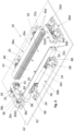
- Fig.1 shows the stacking device 10 with the positioning device 20 formed from positioning jaws 32, 32a, 32b, 32c1, 32c2, 32d1, 32d2 and the vibration units 38, 38a-38d with vibrating jaws 26, 26a-26d and the cell stack 12.
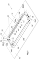
- Fig.2 shows the basic structure of the stacking device 10 without cell stack with the holder 18 in the uppermost end position.
- the holder 18 has the stacking table 60 to which the plurality of positioning jaws 32, 32a, 32b, 32c1, 32c2, 32d1, 32d2 are attached.
- the positioning jaws 32, 32a, 32b, 32c1, 32c2, 32d1, 32d2 are arranged on the circumference of the repeat component(s) 14, 16 fixedly on the stacking table 60 and can be arranged over the entire length of a side - see the positioning jaw 32a, 32b of the first and second arrangement 36a, 36b - or only over a partial area of a side c, d - see the positioning jaws 28c1, 28c2, 28d1, 28d2 of the third and fourth arrangement 36c, 36d - so that the stacking of a cell stack 12 takes place within the positioning jaws 32, 32a, 32b, 32c1, 32c2, 32d1, 32d2. It is also possible to arrange several positioning jaws 28c1, 28c2, 28d1, 28d2 on one side.
- the positioning jaws 32, 32a, 32b, 32c1, 32c2, 32d1, 32d2 serve to pick up a cell stack 12 and to bring it into position and to hold it in position.
- the positioning jaws 32, 32a, 32b, 32c1, 32c2, 32d1, 32d2 are designed in the upper area with an insertion phase - shown here as insertion bevel 64, can also be rounded.
- the vibration units 38, 38a-38d as the upper part of the stacking device 10 and the positioning device 20, like the positioning jaws 32, 32a, 32b, 32c1, 32c2, 32d1, 32d2, are arranged on the circumference of the repeating component 14, 16 firmly on the base plate 60 so that the stacking of a cell stack 12 takes place within the vibration units 38, 38a-38d (see Fig.1 ).
- vibration units 38, 38a-38d The structure and function of the vibration units 38, 38a-38d are explained below using Fig. 4 to 7 described using a vibration unit 38, 38c as an example.
- the vibrating jaw 26, 26c, 26d is caused to vibrate by the vibration generator 24.
- the vibration oscillations are directed via a linear bearing unit 66 so that the movement of the vibrating jaw 26, 26c, 26d takes place in a horizontal plane orthogonal to the edge of the repeat component 14, 16.
- Each vibration unit 38, 38a-38d is thus firmly connected to the base plate 60 of the stacking device 10 via one or more linear bearing units 66.
- Vibration motors or structure-borne sound transducers are suitable as vibration generators 24 .
- the vibrating jaws 26, 26c are designed in the upper area with an insertion phase - rounded or bevelled edge 74.
- the vibration unit 38, 38a-38d of each of the arrangements 36, 36a-36d in the illustrated embodiment has at least two spaced-apart bearings 70 for linearly movable mounting of the associated vibrating jaw 26, 26a-26d and at least one preloading element 72 for preloading the vibrating jaw 26, 26a-26d against a first end stop 74.
- the vibrating jaw 26, 26a-26d is arranged furthest towards the center of the holder 18. Furthermore, an adjustable second end stop 76 is provided for limiting the movement of the vibrating jaw 26, 26a-26d.
- the vibrating jaw 26, 26a-26d is mounted on the bearing 70, which has the pre-tensioning element 72 and at least one preferably adjustable stop 74, 76, so as to be movable between two end positions.
- the vibrating jaw 26, 26a-26d is designed to oscillate between a first end position delimited by the first end stop 74, in which the vibrating jaw contact surface 28 and the positioning jaw contact surface 34 are aligned with one another - i.e. are in particular flush with one another - and a second end position delimited by the second end stop 76, in which the vibrating jaw contact surface 28 is at least partially further away from the receptacle 18 for the cell stack 12 than the positioning jaw contact surface 34.
- the vibration unit 38, 38c in the specific embodiment shown has a base plate 78 for fastening to the base plate 60, a housing 80 for each of the at least two bearings 70, a linear guide 82 accommodated in the housing 80, a shaft 84 guided linearly therein, on which in the embodiment shown here the first end stop 74 is formed, for example as an integral flange or projection or as a separate element or the like, a spring 86, for example a helical compression spring arranged around the shaft 84, as a prestressing element 72, a vibrating plate 88 which is attached to the shafts 84 of the spaced-apart bearings 70 and thus vibrates and to which the vibrating jaw 26, 26c and the vibration generator 24 are attached, the second end stop 76 which can be adjusted on the respective housing 80, for example by means of an adjusting screw 90, against which the vibrating plate 88 strikes, and a tuning plate 92 which is used to adjust the position of the vibrating jaw 26, 26c on
- the vibrating jaw 26, 26c is U-shaped in cross-section with a first leg 94, on which the vibrating jaw contact surface 28 and the projection-recess formation 42 are formed, and a second leg 96, which is connected to the shaft 84 and thus to the bearing 70 via the tuning plate 92 and the vibrating plate 88 and to which at least one of the vibration generators 24 is connected, and a web 98 which engages over a body 100 of the associated positioning jaw 32, 32c1, 32c2.
- the vibrating jaw 26, 26c is provided with the rounded or beveled edge 68 to form the introduction phase for the repeat component 14, 16.
- connection points 104 are provided for the optional arrangement of at least one vibration generator 24 or several vibration generators 24, so that natural frequencies can also be adjusted in this way.
- the setting of the connection point 104 is indicated by elongated holes 103 on a fastening plate 105 of the vibration generators 24.
- two vibration generators 24 are provided in the setting shown here as an example, while in the setting shown here, one vibration generator 24 is provided in each case on the shorter vibration units 38c, 38d.
- the vibration unit 38, 3a-38d thus has one or more of the linear bearing unit(s) 66, which is/are arranged on the base plate 78.
- a linear bearing unit 66 comprises the housing 80, in which the shaft 84 is mounted via the linear guide 82.
- This shaft 80 is geometrically designed in such a way that its movement in the horizontal plane towards the cell stack 12, hereinafter referred to as the forward direction, is limited.
- This axial securing of the shaft 84 towards the front can be ensured by a shoulder or an additional component, e.g. a shaft locking ring.
- the pre-tensioning element 72, such as the spring 86 ensures that the shaft 84 is pressed forwards in a horizontal plane against this first end stop 74.
- This spring 86 in turn has the function of enabling a movement of the vibrating plate 88 in a horizontal plane forwards, towards the cell stack 12, or backwards, away from the cell stack 12. This movement is also carried out by the vibrating jaw 26, 26a-26d, which is connected to the vibrating plate 88 via the tuning plate 92. The movement backwards (away from the cell stack 12) can be limited and adjusted by the second end stop 76.
- the movement is generated by the vibration generator 24, as previously described.
- the natural frequency of the vibrating jaw 26, 26a-26d and thus the dynamic behavior of the components can be adjusted, which is responsible for correcting the position of the repeating component(s) 14, 16 in the horizontal plane and thus for the positioning accuracy of the cell stack.
- a control 102 is also provided, by means of which the individual vibration generators 24 of each arrangement 36, 36a-36d can be controlled individually, even differently.
- the frequency of one or more vibrating jaws 26, 26a-26d can be flexibly adjusted, which is particularly advantageous when changing the format of the repeat component(s) 14, 16. Even inactive operation of one or more vibration units 38, 38a-38d is possible, so that one or more vibrating jaws 26, 26a-26d are used only as an insertion aid. For this purpose, the vibrating jaw(s) 26, 26a-26d are locked in the front position by the pre-tensioning element 72, such as the spring 86.
- a further advantage of the independent arrangement and control of the individual vibrating jaws 26, 26a-26d is that the opposing vibrating jaws 26a and 26b or 26c and 26d can be operated in parallel, in opposite directions, or even offset (see Fig.4 This can further influence the required stacking and positioning accuracy.
- the positioning jaw 32, 32a-32d2 with the body 72 is block-shaped or strip-shaped.
- the positioning jaw 32, 32a-32d2 is preferably bevelled or rounded at an upper end region above the positioning jaw contact surface 34 to form the insertion bevel 64.
- the positioning jaw 32, 32a-32d2 is designed such that the projection-recess formation 42 is formed on a side surface facing the receptacle 18 for receiving the cell stack 12 - the positioning jaw contact surface 34.
- the vibrating jaw(s) 26, 26a-26d and the positioning jaw(s) 32, 32a-32d2 are designed to overlap geometrically.
- the vibrating jaw 26, 26a-26d can be geometrically designed in such a way that the alignment of the repeat component(s) 14, 16 only occurs in one or more partial areas.
- the vibrating jaw 26 and the associated positioning jaw 32 are provided with the complementary projection-recess formations 42.
- the projection-recess formation 42 in the positioning jaw 32, 32a-32d2 and the vibrating jaw 26, 26a-26d of the first embodiment is shown as a comb structure 44 with grooves 48, 52 formed between teeth 46, 50. Vibrating jaw teeth 46 engage in positioning jaw grooves 52, and positioning jaw teeth 50 engage in vibrating jaw grooves 48.
- the comb structure 44 extends here over the entire width of the contact surfaces 28, 34.
- Fig. 9a to 9d a sequence of images is shown which corresponds to the depositing or insertion of a repeat component 14, from the first rough alignment of a repeat component 14 in the horizontal plane through the insertion phase - on the bevelled edge 68 - of a vibrating jaw 26, 26c in the rear position (see Fig. 9a ), via the fine position correction by the stroke of the vibrating jaw 26, 26c into the front position (see Fig. 9b ), up to the reception of a repeat component(s) 14 by one or more positioning jaws 32, 32c1, 32c2 by the further lowering movement of one or more repeat components 14 (see Fig. 9c and 9d ).
- the stacking device 10 also has the positioning device 20 arranged around the receptacle 18 with the arrangements 36, 36a1, 36a2, 36b1, 36b2, 36c, 36d, which consist of vibration generators 24 that can be set into vibration individually controlled. Vibrating jaws 26, 26a1, 26a2, 26b1, 26b2, 26c, 26d and positioning jaws 32, 32a1, 32a2, 32b1, 32b2, 32c, 32d which are stationary during operation.
- the vibration units 38, 38a1, 38a2, 38b1, 38b2, 38c, 38d, on which the vibrating jaws 26, 26a1, 26a2, 26b1, 26b2, 26c, 26d are formed, are constructed differently here, so that the vibrating jaws 26, 26a1, 26a2, 26b1, 26b2, 26c, 26d move in an oscillating manner along the curved path 56, here formed as a circular path.
- the holder 18 is provided with a movable lateral guide 106, as described and shown in detail in the literature references [3] and [4].
- a movable lateral guide 106 as described and shown in detail in the literature references [3] and [4].
- Fig.10 shows the upper part of the stacking device 10 according to the second embodiment - also called rotary variant due to the rotary oscillating movement of the vibrating jaws 26, 26a1, 26a2, 26b1, 26b2, 26c, 26d.
- Fig. 11 shows the lower part of the stacking device 10.
- the upper part is designed as a vibration device 108.
- the vibration device 108 has the base plate 62, which is connected to a base frame 112 of the stacking device 10 via a lifting unit 110 (not shown in detail).
- the vibration units 38, 38a1, 38a2, 38b1, 38b2, 38c, 38d are mounted on the base plate 62 and can be aligned to the specific features of the repeat components 14, 16 to be processed.
- the vibration device 108 shown is located directly above the Fig. 11 shown holder 18, which receives the aligned repeat components 14, 16 in the ongoing stacking process and stores them in the correct position.
- the holder 18 has the base frame 112 with the guides 106.
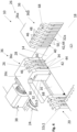
- vibration device 108 The combination of vibration device 108 and holder 18 is in Fig. 12 shown.
- the Z axis Due to the mechanical properties of the repeat components 14, 16, only a very small number of components lying on top of one another can be aligned without damage. This number of repeat components, which are located within the vibration device 108 and are thus actively aligned by the vibration, can be adjusted by the lifting axis (Z axis) of the height compensation. To do this, the Z axis with its actuators cycles downwards by the corresponding material thickness after a repeat component has been deposited or thrown in, in order to simultaneously keep the deposit position of the repeat components constant during the stacking process. The actuators of the Z axis move the support device 22, on which the repeat components 14, 16 are deposited, in the vertical direction in the base frame 112.
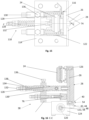
- Fig. 13 a perspective view of the vibration unit 38, 38c, Fig. 14 a side view, Fig. 15 a top view and Fig. 16 a section through the vibration unit 38, 38c along the line CC of Fig. 15 .
- the vibration unit 38, 38c comprises a base unit 114, an oscillator unit 116 and an adjustment unit 118.
- the oscillator unit 116 comprises the vibrating jaw 26, 26c as the actual oscillator, which is rotatably connected to the base unit 114 via the bearing 70.
- the bearing 70 here comprises conventional roller bearings 120, a fastening shaft 122 and bearing blocks 124.
- the vibration generator 24 is mounted on the vibrating jaw 26, 26c on the side facing away from the cell stack 12.
- the vibrating jaw 26, 26c On the side facing the cell stack 12 the vibrating jaw 26, 26c has an alignment bar 126 on which the vibrating jaw contact surface 28 is formed.
- the vibrating jaw 26, 26c and its dynamic behavior can be adjusted to the respective application by the adjustment unit 118.
- the adjustment unit 118 has at least one pre-tensioning element 72, here designed as a first compression spring 128, and at least one adjustable pre-tensioning unit 130 for adjusting the pre-tensioning force of the pre-tensioning element 72.
- first compression springs 128, with a corresponding number of pre-tensioning units 130 are provided.
- the adjustment unit 118 has an adjustable coupling unit 132 for coupling to the vibrating jaw 26, 26c with an adjustable relative position.
- the coupling unit 132 is coupled to the vibrating jaw 26, 26c in an articulated manner.
- the adjustment unit 118 further comprises a further pre-tensioning element for acting in the opposite direction to the first pre-tensioning element 72.
- the further pre-tensioning element is designed here as a second compression spring 134.
- the adjustment unit 118 has at least one locking element such as a locking screw 136 or a lock nut 138 to secure the adjustment of the at least one preload unit 130 and/or the adjustable coupling unit 132.
- the adjustment unit 118 has the adjustable mechanical end stops 74, 76.
- the vibrating jaw 26, 26c is tensioned via the first two compression springs 128 with the aid of the pre-tensioning units 130 against the second compression spring 134, which is attached to the vibrating jaw 26, 26c with the adjustable coupling unit 132, in accordance with the required dynamic Parameters for the best possible alignment of the repeat components 14, 16.
- the preload units 130 are secured against unwanted rotation by means of the locking screws 136. This ensures a constant preload force of the first compression springs 128. The same applies to securing the coupling unit 132 by means of lock nuts 138. This ensures a constant preload force of the second compression spring 134.
- the stiffness of the vibration system can be fundamentally changed.
- All adjustment elements 128, 130, 132, 134, 136, 138 which serve to regulate or adapt the dynamic behavior of the vibrating jaw 26, 26c acting as an oscillator, are connected to and secured on the base unit 114.
- the front and rear mechanical end stops 74, 76 for limiting the vibration amplitude are also connected to the base unit 114.
- the contact between the vibration unit 38, 38c and the repeat components 14, 16 to be aligned takes place exclusively through the exchangeable alignment bar 126.
- This alignment bar 126 can thus be adapted to the required alignment geometry and matched with regard to the required mechanical properties.
- Fig. 17 shows a perspective view of the arrangement 36, 36b1 formed from a vibration unit 38, 38b1 with the vibrating jaw 26, 26b1 and a positioning jaw 32, 32b1 arranged underneath to explain the structure of the positioning device 10 and to explain the form of the Vibrating jaw 26, 26b1, especially their vibrating jaw contact surface 28 formed here on the alignment bar 126.
- the positioning jaws 32, 32a1-32d of the positioning device 10 of the second embodiment are designed like strips and form the upper end of guide rails of the guides 106.
- the positioning jaw contact surfaces 34 of the positioning jaws 32, 32a1-32d of the holder 18 are provided with an arc shape that corresponds exactly to the arc path 56 of the vibrating jaws 26, 26a1-26d.
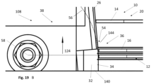
- the positioning jaw contact surfaces 34 are provided with a rounding that corresponds exactly to the swivel radius 142 of the vibrating unit 116 - see Fig. 19 .
- the complementary projection-recess formations 42 are provided on the contact surfaces 28, 34.
- a comb structure 44 with only one tooth 50 is provided on one jaw, here on the positioning jaw 32, 32b1, which fits into a groove 48 on the other jaw, here on the vibrating jaw 26, 26b1.
- the alignment bar 126 and the alignment ie the positioning jaw 32, 32b1 of the holder 18, engage in a "comb-like" manner to also prevent jamming/hooking (see Fig. 17 ).
- Fig. 18 and 19 briefly describes an alignment process using the vibration units 36, 36a1-36d in the vibration device 108 and explains some of its advantages.
- the upstream processes relating to the material feed/feed of the repeat components mean that both repeat components 14, 16 are in free fall before they hit the height compensation in the stacking position. Due to this undefined placement process, the repeat components should now be aligned until the required position tolerances are reached. Due to the changing mechanical properties of the repeat components 14, 16, it is proposed here to support this alignment process with vibration.
- the starting point of the functional analysis is a repetition component 14, which is in a downward movement either by a horizontal throw or a vertical free fall with an initial velocity.
- This repeat component 14 then hits the alignment bar 126 of a vibration unit 36, 36c during insertion and is aligned towards the center of the receptacle 18 of the stacking device 10 by the pivoting movement of the vibrating jaw 26, 26c. Even without active vibration, the repeat components 14 would be aligned due to the funnel-shaped structure of the vibrating unit 116 (see Fig. 18 - this is an advantage of the rotational variant). In particular, the repetition component introduced by means of a horizontal throw is slowed down by the alignment bar 126, whereby the horizontal part of the movement is greatly reduced and a rebound effect is created.
- the influence of the vibration/elongation on the resulting envelope curve or the position tolerances of the repeat components 14 increases.
- the effect is maximum and thus makes it possible to release repeat components 14 that may already be slightly adhering and not positioned precisely enough from the layer below and to deposit them in a positionally accurate manner within the required tolerances.
- the available movement space of the repeat component 14 corresponds to the permissible envelope curve of the entire stack. If the repeat component is located from this point within the alignment guide 106 of the holder 18 of the stacking device 10 and does not show any damage of any kind, it is considered to be aligned.
- the advantage of the rotary approach is that the vibration amplitude automatically decreases during the progressive deposition process (repeat component 14 approaches the deposition position). This means that a larger position tolerance can be covered in the upper area of the vibration device 108, which is then continuously reduced during the free fall of the repeat component 14 until the defined envelope curve of the receptacle 18 of the stacking device 10 is reached.
- the alignment height in other words the guide length at which component alignment is carried out by vibration, can be adapted by adjusting the vibrating jaw 26, 26a1-26d and a corresponding modification of the alignment bar 126.
- the system can also be used passively, as a rigid system in the form of a conventional feed hopper, without replacing components.
- the vibrating jaw 26, 26a1-26d is pressed against the front mechanical end stop 74 only by the pre-tensioning elements 72 - first compression springs 128 in combination with the pre-tensioning units 130. This blocking can also be carried out analogously by the rear mechanical end stop 76.
- the oscillator unit 116 can also be converted into a damper system by selecting appropriate compression springs 128, 134 or other preloading elements in order to absorb the kinetic energy of the repeat component 14 and prevent damage.
- the construction of the vibration device 108 from individual, independent vibration units 38, 38a1-38d also makes it possible to generate specific frequencies and amplitudes, which allows a flexible response to workpiece requirements.
- the vibration generators 24 can be controlled as described above for the first embodiment.
- Preferred embodiments of the invention relate to a system for receiving, positioning and fixing all components required for the construction or manufacture of battery cells, such as lithium-ion battery cells, or fuel cell stacks, such as PEMFC stacks, with a view to production in a large-scale plant.
- Positioning devices 20, stacking devices 10 and stacking methods according to embodiments of the invention are used in the following overall processes I and II for the manufacture of battery cells or fuel cells:
- the production process of a lithium-ion battery cell includes four main process steps: electrode production, cell assembly, cell formation and aging.
- the smallest unit of every lithium-ion cell consists of two electrodes, anode A (e.g. copper graphite coated) and cathode K (e.g. ALU NMC-111 coated), and a separator S that separates the electrodes from each other.
- anode A e.g. copper graphite coated
- cathode K e.g. ALU NMC-111 coated
- separator S is the largest part of a cell and is approximately 1 mm larger than the anode A.
- a stacking process is carried out in which the individual electrodes A, K including separator S are stacked on top of each other in several layers until the desired cell capacity is achieved.
- This process step requires precise positioning of the electrodes in order to ensure high electrical conductivity and thus high power density.
- these components are glued or laminated together in different sequences SASK or SKSA. This unit, consisting of four layers, represents a monocell.
- Electrodes A, K and separator S are examples of repeating components of a cell stack of a battery cell. Other types of battery cells may also have other repeating components.
- the repeating component(s) monocell(s) are positioned/stacked on top of each other.
- the repeating component(s) are usually automatically Handling is set to a position and, if necessary, checked using image processing.
- Applications with vacuum grippers or technology are often used for handling the repeat component(s) monocell, as well as workpiece carriers with integrated hold-down devices that fix the repeat component(s) monocell in position after they have been placed.
- Some embodiments of the invention relate to a stacking device 10 for producing a cell structure of fuel cells, such as a PEMFC stack.
- a stacking device 10 for the manufacturing process of the PEMFC stack is a stacking device 10 which receives alternately introduced repeat components BPP and MEA, aligns them and guides them in a fixed position within the specified position tolerance for the further subsequent processes.
- MEA components are to be introduced alternately from the side and BPP components vertically from above into the stacking device 10 by a feed system to build the stack. Alignment, especially of the MEA components by lateral introduction and the associated change in the direction of movement from horizontal to vertical, is preferably carried out by a guide system of the stacking device. Due to the exclusively vertical depositing movement of the BPP, very little effort is required for alignment/positioning compared to the MEA. The total cycle time for depositing a single cell consisting of BPP and MEA can thus be distributed proportionately to the respective component by the structure of the individual systems. Depending on requirements, it is therefore possible, for example, to allocate proportionately more cycle time to the depositing of the MEA if this process requires more time. In addition, the depositing process can optionally be supported by vibration in the depositing area if necessary, which simplifies the alignment of the last deposited components.
- the positioning device (20) has at least one vibrating jaw (26, 26a, 26a1, 26a2, 26b, 26b1, 26b2, 26c, 26d) with a vibrating jaw contact surface (28) and a positioning jaw (32, 32a1, 32a2, 32b1, 32b2, 32c, 32d) which is rigid during operation and which has a positioning jaw contact surface (34) and is arranged lower than an upper region (30) of the vibrating jaw (26, 26a, 26a1, 26a2, 26b, 26b1, 26b2, 26c, 26d).
- the jaws engage with one another with complementary projection-recess formations (42) on the contact surfaces (28, 34).
- the vibrating jaw moves along an arcuate path (56) during oscillation, wherein a tangent of the arcuate path (56) lies on the positioning jaw contact surface (34).
Landscapes
- Engineering & Computer Science (AREA)
- Manufacturing & Machinery (AREA)
- Chemical & Material Sciences (AREA)
- Chemical Kinetics & Catalysis (AREA)
- Electrochemistry (AREA)
- General Chemical & Material Sciences (AREA)
- Mechanical Engineering (AREA)
- Life Sciences & Earth Sciences (AREA)
- Sustainable Development (AREA)
- Sustainable Energy (AREA)
- Fuel Cell (AREA)
Claims (11)
- Dispositif de positionnement (20) pour positionner les composants répétitifs (14, 16) d'une pile de cellules (12) pour batteries ou piles à combustible à placer les uns sur les autres, comprenant une mâchoire vibrante (26, 26a, 26a1, 26a2, 26b, 26b1, 26b2, 26c, 26d) qui peut être mise en vibration au moyen d'au moins un générateur de vibrations (24) et qui a une surface de contact de mâchoire vibrante (28) pour entrer en contact avec un bord du composant répétitif (14, 16) à poser pour le centrer par vibration, et une mâchoire de positionnement (32, 32a1, 32a2, 32b1, 26b2, 26c, 26d) rigide en fonctionnement et disposée sous une zone supérieure (30) de la mâchoire vibrante (26, 26a1, 26a2, 26b, 26b1, 26b2, 26c, 26d) et ayant une surface de contact de mâchoire de positionnement (34) pour contacter un bord de la pile de cellules (12) à former pour la maintenir en position, dans lequela) la mâchoire de positionnement (32, 32a1, 32a2, 32b1, 32b2, 32c, 32d) et la mâchoire vibrante (26, 26a, 26a1, 26a2, 26b, 26b1, 26b2, 26c, 26d) présentent, sur une zone de mâchoire (40) formant les surfaces de contact (28, 34), une caractéristique complémentaire de saillie et d'évidement (42) par laquelle la mâchoire de positionnement (32, 32a1, 32a2, 32b1, 32b2, 32c, 32d) et la mâchoire vibrante (26, 26a, 26a1, 26a2, 26b1, 26b2, 26c, 26d) s'engagent l'une dans l'autre et/oub) la mâchoire vibrante (26, 26a, 26a1, 26a2, 26b, 26b1, 26b2, 26c, 26d) est conçue pour déplacer une zone d'extrémité (54) de la surface de contact de la mâchoire vibrante (28) située à proximité de la surface de contact de la mâchoire de positionnement (34) le long d'une trajectoire en arc de cercle (56) pendant l'oscillation, une tangente de la trajectoire en arc de cercle (56) se trouvant sur la surface de contact de la mâchoire de positionnement (34).
- Dispositif de positionnement (20) selon la revendication 1, caractérisé en ce que la caractéristique de saillie et d'évidement (42)2.1 est une structure en peigne (44) avec des rainures (48, 52) formées entre les dents (46, 50), dans laquelle les dents de la mâchoire vibrante (46) engagent dans les rainures de la mâchoire de positionnement (52) et les dents de la mâchoire de positionnement (50) engagent dans les rainures de la mâchoire vibrante (48), les surfaces de contact (28, 34) étant formées au moins en partie sur les dents (46, 50), et/ou2.2 s'étend sur toute la largeur des surfaces de contact (28, 34).
- Dispositif de positionnement (20) selon l'une quelconque des revendications précédentes, caractérisé en ce que
un premier agencement (36a, 36a1, 36a2) d'une première mâchoire de positionnement (32a1, 32a2) et d'une première mâchoire vibrante (26a, 26a1, 26a2), et un deuxième agencement (36b, 36b1, 36b2) d'une seconde mâchoire de positionnement (32b1, 32b2) et d'une seconde mâchoire vibrante (26b, 26b1, 26b2) s'opposent sur une première paire de côtés opposés (a, b) d'un réceptacle (18) pour la pile de cellules (12). - Dispositif de positionnement (20) selon la revendication 3, caractérisé en ce qu'un troisième agencement (36c) d'une troisième mâchoire de positionnement (32c) et d'une troisième mâchoire vibrante (26c), et un quatrième agencement (36d) d'une quatrième mâchoire de positionnement (32d) et d'une quatrième mâchoire vibrante (26d) s'opposent sur une deuxième paire de côtés opposés (c, d) du réceptacle (18) de la pile de cellules (12).
- Dispositif de positionnement (20) selon l'une quelconque des revendications 3 ou 4, caractérisé par au moins une ou plusieurs des caractéristiques suivantes5.1 les générateurs de vibrations (24) de différents agencements (36, 36a, 36a1, 36a2, 36b, 36b1, 36b2, 36c, 36d) peuvent être commandés individuellement et/ou différemment,5.2 un dispositif de commande (102) est prévu et conçu pour commander les générateurs de vibrations (24) de manière à ce que5.2a le mouvement des générateurs de vibrations (24) s'effectue par paires dans des directions opposées ou5.2b le mouvement des générateurs de vibrations (24) s'effectue par paires dans la même direction,5.2c chaque générateur de vibrations (24) soit inactif.
- Dispositif de positionnement (20) selon l'une quelconque des revendications précédentes, caractérisé en ce que
la mâchoire vibrante (26, 26a, 26b, 26c, 26d) a une section transversale en forme de U avec une première branche (94), sur laquelle sont formées la surface de contact de la mâchoire vibrante (28) et la caractéristique de saillie et d'évidement (42), et une deuxième branche (96) reliée au générateur de vibrations (24), et une âme (98) qui recouvre un corps (100) de la mâchoire de positionnement (32, 32a1, 32a2, 32b1, 32b2, 32c, 32d). - Dispositif de positionnement (20) selon l'une quelconque des revendications précédentes, caractérisé en ce quela mâchoire de positionnement (32, 32a1, 32a2, 32b1, 32b2, 32c, 32d)7.1 est chanfreinée ou arrondie à une extrémité supérieure au-dessus de la surface de contact de la mâchoire de positionnement (34) pour former une pente d'insertion (64), ou7.2 est arrondi à une extrémité supérieure de la surface de contact de la mâchoire de positionnement (34) de manière correspondante à fleur de ou alignée avec la trajectoire en arc de cercle (56),7.3 est en forme de bloc ou de bande, et/ou7.4 est formé de telle sorte que la caractéristique de saillie et d'évidement (42) est formée sur une surface latérale faisant face à un réceptacle (18) destiné à recevoir la pile de cellules (12), et/ou7.5 s'étend le long d'une direction de hauteur pour guider les bords des composants répétitifs (14, 16) dans la pile de cellules (12) pendant le suivi de la hauteur dans le réceptacle (18).
- Dispositif de positionnement (20) selon l'une quelconque des revendications précédentes, caractérisé en ce quela mâchoire vibrante (26, 26a, 26a1, 26a2, 26b, 26b1, 26b2, 26c, 26d)8.1 oscille entre une première position finale dans laquelle la surface de contact de la mâchoire vibrante (28) et la surface de contact de la mâchoire de positionnement (34) sont alignées l'une par rapport à l'autre, et une deuxième position finale dans laquelle la surface de contact de la mâchoire vibrante (28) est plus éloignée d'un réceptacle (18) pour la pile de cellules (12) que la surface de contact de la mâchoire de positionnement (34), au moins par zones, et/ou8.2 repose sur un palier (70) qui comporte un élément de pré-tension (72) et au moins une butée (74, 76), de préférence réglable, de sorte qu'il peut être déplacé entre deux positions finales, et/ou8.3 peut être relié au générateur de vibrations (24) ou éventuellement à plusieurs générateurs de vibrations (24) à des points de connexion (104) variables de manière sélective afin de régler les fréquences naturelles, et/ou8.4a peut osciller linéairement d'avant en arrière perpendiculairement à la surface de contact de la mâchoire vibrante (28), ou8.4b oscille autour d'un axe (58) aligné horizontalement et parallèlement à la surface de contact de la mâchoire vibrante (28), ou8.4c tourne d'avant en arrière autour d'un axe (58) aligné horizontalement et parallèlement à la surface de contact de la mâchoire vibrante pendant l'oscillation.
- Dispositif d'empilage (10) pour former une pile de cellules (12) pour une cellule de batterie ou une pile à combustible à partir de composants répétitifs (14, 16) à placer l'un sur l'autre, comprenant au moins un dispositif de positionnement (20) selon l'une quelconque des revendications précédentes et un réceptacle (18) avec un dispositif de support (22) mobile dans la direction de la hauteur pour supporter et ajuster la hauteur de la pile de cellules (12) pendant l'empilage.
- Procédé d'empilage pour former une pile de cellules (12) pour une cellule de batterie ou une pile à combustible à partir d'une pluralité de composants répétitifs (14, 16) à placer l'un sur l'autre, comprenanta) fournir un dispositif d'empilage (10) selon la revendication 9,b) déposer un composant répétitif (14, 16),c) centrer le composant répétitif (14, 16) en faisant vibrer la mâchoire vibrante (26, 26a, 26a1, 26a2, 26b, 26b1, 26b2, 26c, 26d) pour l'amener en contact avec la surface de contact de la mâchoire de positionnement (34),e) répéter les étapes a) à c) avec des composants répétitifs supplémentaires (14, 16) de manière à former la pile de cellules (12).
- Procédé d'empilage selon la revendication 10, caractérisée par l'étape à effectuer après l'étape c):d) déplacer le dispositif de support (22) vers le bas,les étapes a) à d) étant répétées avec les autres composants répétitifs (14, 16) à l'étape e).
Priority Applications (4)
| Application Number | Priority Date | Filing Date | Title |
|---|---|---|---|
| EP21197541.2A EP4152452B1 (fr) | 2021-09-17 | 2021-09-17 | Dispositif de positionnement, dispositif d'empilement et procédé d'empilement pour composants d'un empilement d'éléments de batterie ou de piles à combustible |
| HUE21197541A HUE067121T2 (hu) | 2021-09-17 | 2021-09-17 | Pozícionáló eszköz, kötegelõ eszköz és kötegelõ eljárás akkumulátor- vagy üzemanyagcellák számára szolgáló cellaköteg ismétlõdõ komponenseihez |
| US17/944,247 US20230091085A1 (en) | 2021-09-17 | 2022-09-14 | Positioning device, stacking device and stacking method for repeating components of a cell stack for battery or fuel cells |
| CN202211137511.9A CN115832393A (zh) | 2021-09-17 | 2022-09-19 | 用于电池堆重复部件的定位装置、堆叠装置和堆叠方法 |
Applications Claiming Priority (1)
| Application Number | Priority Date | Filing Date | Title |
|---|---|---|---|
| EP21197541.2A EP4152452B1 (fr) | 2021-09-17 | 2021-09-17 | Dispositif de positionnement, dispositif d'empilement et procédé d'empilement pour composants d'un empilement d'éléments de batterie ou de piles à combustible |
Publications (3)
| Publication Number | Publication Date |
|---|---|
| EP4152452A1 EP4152452A1 (fr) | 2023-03-22 |
| EP4152452C0 EP4152452C0 (fr) | 2024-05-01 |
| EP4152452B1 true EP4152452B1 (fr) | 2024-05-01 |
Family
ID=77838725
Family Applications (1)
| Application Number | Title | Priority Date | Filing Date |
|---|---|---|---|
| EP21197541.2A Active EP4152452B1 (fr) | 2021-09-17 | 2021-09-17 | Dispositif de positionnement, dispositif d'empilement et procédé d'empilement pour composants d'un empilement d'éléments de batterie ou de piles à combustible |
Country Status (4)
| Country | Link |
|---|---|
| US (1) | US20230091085A1 (fr) |
| EP (1) | EP4152452B1 (fr) |
| CN (1) | CN115832393A (fr) |
| HU (1) | HUE067121T2 (fr) |
Families Citing this family (4)
| Publication number | Priority date | Publication date | Assignee | Title |
|---|---|---|---|---|
| WO2024008332A1 (fr) * | 2022-07-07 | 2024-01-11 | Grob-Werke Gmbh & Co. Kg | Dispositif de positionnement, dispositif d'empilement et procédé d'empilement pour composants de répétition d'un empilement d'éléments pour éléments de batterie ou piles à combustible |
| EP4723261A1 (fr) * | 2023-05-24 | 2026-04-08 | CPS Technology Holdings LLC | Système de chargement de plaque d'électrode |
| CN116742095B (zh) * | 2023-08-16 | 2023-12-08 | 惠州绿保科技有限公司 | 一种氢燃料电池电堆双工位连续堆叠装置及堆叠方法 |
| CN117564977A (zh) * | 2023-12-01 | 2024-02-20 | 上海骥翀氢能科技有限公司 | 一种电池堆定位工装 |
Family Cites Families (3)
| Publication number | Priority date | Publication date | Assignee | Title |
|---|---|---|---|---|
| JP6331201B2 (ja) * | 2013-10-31 | 2018-05-30 | エルジー・ケム・リミテッド | 電池セル積層ジグ |
| EP3677102B1 (fr) * | 2017-12-13 | 2024-11-06 | Hewlett-Packard Development Company, L.P. | Procédé et système d'empilement de substrats imprimés |
| DE102019110472A1 (de) * | 2019-04-23 | 2020-10-29 | Grob-Werke Gmbh & Co. Kg | Vorrichtung und Verfahren zum Herstellen eines Zellstapels |
-
2021
- 2021-09-17 HU HUE21197541A patent/HUE067121T2/hu unknown
- 2021-09-17 EP EP21197541.2A patent/EP4152452B1/fr active Active
-
2022
- 2022-09-14 US US17/944,247 patent/US20230091085A1/en not_active Abandoned
- 2022-09-19 CN CN202211137511.9A patent/CN115832393A/zh active Pending
Also Published As
| Publication number | Publication date |
|---|---|
| CN115832393A (zh) | 2023-03-21 |
| EP4152452A1 (fr) | 2023-03-22 |
| EP4152452C0 (fr) | 2024-05-01 |
| US20230091085A1 (en) | 2023-03-23 |
| HUE067121T2 (hu) | 2024-10-28 |
Similar Documents
| Publication | Publication Date | Title |
|---|---|---|
| EP4152452B1 (fr) | Dispositif de positionnement, dispositif d'empilement et procédé d'empilement pour composants d'un empilement d'éléments de batterie ou de piles à combustible | |
| EP3759760B1 (fr) | Dispositif et procédé de fabrication d'un empilement de cellules | |
| EP2209202B1 (fr) | Procédé de fonctionnement d'un entraînement piézo-linéaire doté d'un groupe de piézo-actionneurs | |
| WO2022128953A1 (fr) | Dispositif d'empilement, station d'empilement, dispositif de production, procédé d'empilement et procédé de production pour une structure en couches de pile à combustible | |
| DE3542443C2 (fr) | ||
| EP2011583A1 (fr) | Machine de formage de fil | |
| DE19938954A1 (de) | Piezoelektrischer Antrieb, insbesondere zur Erzeugung von Rotations- oder Translationsbewegungen, die stetig oder schrittweise erfolgen können | |
| EP3558825B1 (fr) | Magasin à cigarettes conçu pour une machine d'emballage de cigarettes et procédé de fonctionnement correspondant | |
| DE102013204026B4 (de) | Aktoranordnung für einen Ultraschallmotor | |
| WO2010006589A2 (fr) | Système de gravure au laser pour la structuration de substrats pour modules solaires à couche mince | |
| EP3482215B1 (fr) | Dispositif de pipettage comprenant un embout de pipetage déplaçable avec un écart entre les agrafes sur les rails | |
| DE102006048238B4 (de) | Piezolinearantrieb | |
| DE2903556A1 (de) | Zweikoordinatenpositioniereinrichtung | |
| EP1899245A1 (fr) | Transporteur vibrant lineaire | |
| DE102007031639A1 (de) | Vibrationslinearförderer | |
| DE102012221892B4 (de) | Antriebsvorrichtung und -verfahren zur linearen oder rotatorischen Positionierung | |
| DE102007023963B4 (de) | Vorrichtung für einen Schwingungserreger | |
| WO2022199885A1 (fr) | Procédé et dispositif de production d'un empilement d'électrodes | |
| DE60307514T2 (de) | Einfüge- und Extraktionsvorrichtung für rotierbare Datenträgerplatten | |
| DE102011054300A1 (de) | Linear-Vibrationsförderer | |
| EP4552174A1 (fr) | Dispositif de positionnement, dispositif d'empilement et procédé d'empilement pour composants de répétition d'un empilement d'éléments pour éléments de batterie ou piles à combustible | |
| WO2022129505A1 (fr) | Noyau feuilleté de stator destiné à recevoir au moins une unité de bobine, segment de stator, stator, segment de rotor, rotor, générateur, éolienne et procédé de fabrication d'un segment de rotor | |
| DE102006052455B4 (de) | Bestückkopf zum Bestücken von Substraten mit elektrischen Bauteilen mit einem Dreh-Hub-Motor | |
| WO1998018194A1 (fr) | Mecanisme d'entrainement lineaire a structure modulaire et procede de fabrication d'une unite active faisant partie d'un tel mecanisme d'entrainement lineaire | |
| EP1048086A1 (fr) | Dispositif d'entrainement piezoelectrique |
Legal Events
| Date | Code | Title | Description |
|---|---|---|---|
| PUAI | Public reference made under article 153(3) epc to a published international application that has entered the european phase |
Free format text: ORIGINAL CODE: 0009012 |
|
| STAA | Information on the status of an ep patent application or granted ep patent |
Free format text: STATUS: THE APPLICATION HAS BEEN PUBLISHED |
|
| AK | Designated contracting states |
Kind code of ref document: A1 Designated state(s): AL AT BE BG CH CY CZ DE DK EE ES FI FR GB GR HR HU IE IS IT LI LT LU LV MC MK MT NL NO PL PT RO RS SE SI SK SM TR |
|
| P01 | Opt-out of the competence of the unified patent court (upc) registered |
Effective date: 20230527 |
|
| STAA | Information on the status of an ep patent application or granted ep patent |
Free format text: STATUS: REQUEST FOR EXAMINATION WAS MADE |
|
| 17P | Request for examination filed |
Effective date: 20230802 |
|
| RBV | Designated contracting states (corrected) |
Designated state(s): AL AT BE BG CH CY CZ DE DK EE ES FI FR GB GR HR HU IE IS IT LI LT LU LV MC MK MT NL NO PL PT RO RS SE SI SK SM TR |
|
| GRAP | Despatch of communication of intention to grant a patent |
Free format text: ORIGINAL CODE: EPIDOSNIGR1 |
|
| STAA | Information on the status of an ep patent application or granted ep patent |
Free format text: STATUS: GRANT OF PATENT IS INTENDED |
|
| RIC1 | Information provided on ipc code assigned before grant |
Ipc: H01M 10/04 20060101ALI20240118BHEP Ipc: B65H 31/38 20060101ALI20240118BHEP Ipc: H01M 8/2404 20160101AFI20240118BHEP |
|
| INTG | Intention to grant announced |
Effective date: 20240205 |
|
| GRAS | Grant fee paid |
Free format text: ORIGINAL CODE: EPIDOSNIGR3 |
|
| GRAA | (expected) grant |
Free format text: ORIGINAL CODE: 0009210 |
|
| STAA | Information on the status of an ep patent application or granted ep patent |
Free format text: STATUS: THE PATENT HAS BEEN GRANTED |
|
| AK | Designated contracting states |
Kind code of ref document: B1 Designated state(s): AL AT BE BG CH CY CZ DE DK EE ES FI FR GB GR HR HU IE IS IT LI LT LU LV MC MK MT NL NO PL PT RO RS SE SI SK SM TR |
|
| REG | Reference to a national code |
Ref country code: GB Ref legal event code: FG4D Free format text: NOT ENGLISH |
|
| RIN1 | Information on inventor provided before grant (corrected) |
Inventor name: BIBERACHER, TOBIAS Inventor name: JANUSCH, TIM Inventor name: RATHGEB, MICHAEL Inventor name: STOLZ, JOACHIM |
|
| REG | Reference to a national code |
Ref country code: CH Ref legal event code: EP |
|
| REG | Reference to a national code |
Ref country code: IE Ref legal event code: FG4D Free format text: LANGUAGE OF EP DOCUMENT: GERMAN |
|
| REG | Reference to a national code |
Ref country code: DE Ref legal event code: R096 Ref document number: 502021003544 Country of ref document: DE |
|
| U01 | Request for unitary effect filed |
Effective date: 20240516 |
|
| P04 | Withdrawal of opt-out of the competence of the unified patent court (upc) registered |
Effective date: 20240525 |
|
| U07 | Unitary effect registered |
Designated state(s): AT BE BG DE DK EE FI FR IT LT LU LV MT NL PT SE SI Effective date: 20240529 |
|
| PG25 | Lapsed in a contracting state [announced via postgrant information from national office to epo] |
Ref country code: IS Free format text: LAPSE BECAUSE OF FAILURE TO SUBMIT A TRANSLATION OF THE DESCRIPTION OR TO PAY THE FEE WITHIN THE PRESCRIBED TIME-LIMIT Effective date: 20240901 |
|
| PG25 | Lapsed in a contracting state [announced via postgrant information from national office to epo] |
Ref country code: HR Free format text: LAPSE BECAUSE OF FAILURE TO SUBMIT A TRANSLATION OF THE DESCRIPTION OR TO PAY THE FEE WITHIN THE PRESCRIBED TIME-LIMIT Effective date: 20240501 |
|
| PG25 | Lapsed in a contracting state [announced via postgrant information from national office to epo] |
Ref country code: GR Free format text: LAPSE BECAUSE OF FAILURE TO SUBMIT A TRANSLATION OF THE DESCRIPTION OR TO PAY THE FEE WITHIN THE PRESCRIBED TIME-LIMIT Effective date: 20240802 |
|
| PG25 | Lapsed in a contracting state [announced via postgrant information from national office to epo] |
Ref country code: ES Free format text: LAPSE BECAUSE OF FAILURE TO SUBMIT A TRANSLATION OF THE DESCRIPTION OR TO PAY THE FEE WITHIN THE PRESCRIBED TIME-LIMIT Effective date: 20240501 |
|
| PG25 | Lapsed in a contracting state [announced via postgrant information from national office to epo] |
Ref country code: PL Free format text: LAPSE BECAUSE OF FAILURE TO SUBMIT A TRANSLATION OF THE DESCRIPTION OR TO PAY THE FEE WITHIN THE PRESCRIBED TIME-LIMIT Effective date: 20240501 |
|
| REG | Reference to a national code |
Ref country code: HU Ref legal event code: AG4A Ref document number: E067121 Country of ref document: HU |
|
| U20 | Renewal fee for the european patent with unitary effect paid |
Year of fee payment: 4 Effective date: 20240925 |
|
| PG25 | Lapsed in a contracting state [announced via postgrant information from national office to epo] |
Ref country code: PL Free format text: LAPSE BECAUSE OF FAILURE TO SUBMIT A TRANSLATION OF THE DESCRIPTION OR TO PAY THE FEE WITHIN THE PRESCRIBED TIME-LIMIT Effective date: 20240501 Ref country code: NO Free format text: LAPSE BECAUSE OF FAILURE TO SUBMIT A TRANSLATION OF THE DESCRIPTION OR TO PAY THE FEE WITHIN THE PRESCRIBED TIME-LIMIT Effective date: 20240801 Ref country code: IS Free format text: LAPSE BECAUSE OF FAILURE TO SUBMIT A TRANSLATION OF THE DESCRIPTION OR TO PAY THE FEE WITHIN THE PRESCRIBED TIME-LIMIT Effective date: 20240901 Ref country code: HR Free format text: LAPSE BECAUSE OF FAILURE TO SUBMIT A TRANSLATION OF THE DESCRIPTION OR TO PAY THE FEE WITHIN THE PRESCRIBED TIME-LIMIT Effective date: 20240501 Ref country code: GR Free format text: LAPSE BECAUSE OF FAILURE TO SUBMIT A TRANSLATION OF THE DESCRIPTION OR TO PAY THE FEE WITHIN THE PRESCRIBED TIME-LIMIT Effective date: 20240802 Ref country code: ES Free format text: LAPSE BECAUSE OF FAILURE TO SUBMIT A TRANSLATION OF THE DESCRIPTION OR TO PAY THE FEE WITHIN THE PRESCRIBED TIME-LIMIT Effective date: 20240501 Ref country code: RS Free format text: LAPSE BECAUSE OF FAILURE TO SUBMIT A TRANSLATION OF THE DESCRIPTION OR TO PAY THE FEE WITHIN THE PRESCRIBED TIME-LIMIT Effective date: 20240801 |
|
| P05 | Withdrawal of opt-out of the competence of the unified patent court (upc) changed |
Free format text: CASE NUMBER: APP_30550/2024 Effective date: 20240529 |
|
| PG25 | Lapsed in a contracting state [announced via postgrant information from national office to epo] |
Ref country code: CZ Free format text: LAPSE BECAUSE OF FAILURE TO SUBMIT A TRANSLATION OF THE DESCRIPTION OR TO PAY THE FEE WITHIN THE PRESCRIBED TIME-LIMIT Effective date: 20240501 |
|
| PG25 | Lapsed in a contracting state [announced via postgrant information from national office to epo] |
Ref country code: SK Free format text: LAPSE BECAUSE OF FAILURE TO SUBMIT A TRANSLATION OF THE DESCRIPTION OR TO PAY THE FEE WITHIN THE PRESCRIBED TIME-LIMIT Effective date: 20240501 Ref country code: RO Free format text: LAPSE BECAUSE OF FAILURE TO SUBMIT A TRANSLATION OF THE DESCRIPTION OR TO PAY THE FEE WITHIN THE PRESCRIBED TIME-LIMIT Effective date: 20240501 |
|
| PG25 | Lapsed in a contracting state [announced via postgrant information from national office to epo] |
Ref country code: SM Free format text: LAPSE BECAUSE OF FAILURE TO SUBMIT A TRANSLATION OF THE DESCRIPTION OR TO PAY THE FEE WITHIN THE PRESCRIBED TIME-LIMIT Effective date: 20240501 |
|
| PG25 | Lapsed in a contracting state [announced via postgrant information from national office to epo] |
Ref country code: SM Free format text: LAPSE BECAUSE OF FAILURE TO SUBMIT A TRANSLATION OF THE DESCRIPTION OR TO PAY THE FEE WITHIN THE PRESCRIBED TIME-LIMIT Effective date: 20240501 Ref country code: SK Free format text: LAPSE BECAUSE OF FAILURE TO SUBMIT A TRANSLATION OF THE DESCRIPTION OR TO PAY THE FEE WITHIN THE PRESCRIBED TIME-LIMIT Effective date: 20240501 Ref country code: RO Free format text: LAPSE BECAUSE OF FAILURE TO SUBMIT A TRANSLATION OF THE DESCRIPTION OR TO PAY THE FEE WITHIN THE PRESCRIBED TIME-LIMIT Effective date: 20240501 Ref country code: CZ Free format text: LAPSE BECAUSE OF FAILURE TO SUBMIT A TRANSLATION OF THE DESCRIPTION OR TO PAY THE FEE WITHIN THE PRESCRIBED TIME-LIMIT Effective date: 20240501 |
|
| REG | Reference to a national code |
Ref country code: DE Ref legal event code: R097 Ref document number: 502021003544 Country of ref document: DE |
|
| PLBE | No opposition filed within time limit |
Free format text: ORIGINAL CODE: 0009261 |
|
| STAA | Information on the status of an ep patent application or granted ep patent |
Free format text: STATUS: NO OPPOSITION FILED WITHIN TIME LIMIT |
|
| 26N | No opposition filed |
Effective date: 20250204 |
|
| PG25 | Lapsed in a contracting state [announced via postgrant information from national office to epo] |
Ref country code: MC Free format text: LAPSE BECAUSE OF FAILURE TO SUBMIT A TRANSLATION OF THE DESCRIPTION OR TO PAY THE FEE WITHIN THE PRESCRIBED TIME-LIMIT Effective date: 20240501 |
|
| REG | Reference to a national code |
Ref country code: CH Ref legal event code: PL |
|
| PG25 | Lapsed in a contracting state [announced via postgrant information from national office to epo] |
Ref country code: CH Free format text: LAPSE BECAUSE OF NON-PAYMENT OF DUE FEES Effective date: 20240930 |
|
| PG25 | Lapsed in a contracting state [announced via postgrant information from national office to epo] |
Ref country code: IE Free format text: LAPSE BECAUSE OF NON-PAYMENT OF DUE FEES Effective date: 20240917 |
|
| PGFP | Annual fee paid to national office [announced via postgrant information from national office to epo] |
Ref country code: HU Payment date: 20250911 Year of fee payment: 5 Ref country code: GB Payment date: 20250923 Year of fee payment: 5 |
|
| U20 | Renewal fee for the european patent with unitary effect paid |
Year of fee payment: 5 Effective date: 20250923 |
|
| PG25 | Lapsed in a contracting state [announced via postgrant information from national office to epo] |
Ref country code: CY Free format text: LAPSE BECAUSE OF FAILURE TO SUBMIT A TRANSLATION OF THE DESCRIPTION OR TO PAY THE FEE WITHIN THE PRESCRIBED TIME-LIMIT; INVALID AB INITIO Effective date: 20210917 |