EP4152092A1 - Lichtquellensystem und laserprojektionsanzeigevorrichtung - Google Patents
Lichtquellensystem und laserprojektionsanzeigevorrichtung Download PDFInfo
- Publication number
- EP4152092A1 EP4152092A1 EP21817854.9A EP21817854A EP4152092A1 EP 4152092 A1 EP4152092 A1 EP 4152092A1 EP 21817854 A EP21817854 A EP 21817854A EP 4152092 A1 EP4152092 A1 EP 4152092A1
- Authority
- EP
- European Patent Office
- Prior art keywords
- light source
- nonlinear optical
- infrared laser
- laser
- source system
- Prior art date
- Legal status (The legal status is an assumption and is not a legal conclusion. Google has not performed a legal analysis and makes no representation as to the accuracy of the status listed.)
- Granted
Links
Images


Classifications
-
- G—PHYSICS
- G03—PHOTOGRAPHY; CINEMATOGRAPHY; ANALOGOUS TECHNIQUES USING WAVES OTHER THAN OPTICAL WAVES; ELECTROGRAPHY; HOLOGRAPHY
- G03B—APPARATUS OR ARRANGEMENTS FOR TAKING PHOTOGRAPHS OR FOR PROJECTING OR VIEWING THEM; APPARATUS OR ARRANGEMENTS EMPLOYING ANALOGOUS TECHNIQUES USING WAVES OTHER THAN OPTICAL WAVES; ACCESSORIES THEREFOR
- G03B21/00—Projectors or projection-type viewers; Accessories therefor
- G03B21/14—Details
- G03B21/20—Lamp housings
- G03B21/206—Control of light source other than position or intensity
-
- G—PHYSICS
- G02—OPTICS
- G02F—OPTICAL DEVICES OR ARRANGEMENTS FOR THE CONTROL OF LIGHT BY MODIFICATION OF THE OPTICAL PROPERTIES OF THE MEDIA OF THE ELEMENTS INVOLVED THEREIN; NON-LINEAR OPTICS; FREQUENCY-CHANGING OF LIGHT; OPTICAL LOGIC ELEMENTS; OPTICAL ANALOGUE/DIGITAL CONVERTERS
- G02F1/00—Devices or arrangements for the control of the intensity, colour, phase, polarisation or direction of light arriving from an independent light source, e.g. switching, gating or modulating; Non-linear optics
- G02F1/35—Non-linear optics
- G02F1/353—Frequency conversion, i.e. wherein a light beam is generated with frequency components different from those of the incident light beams
-
- G—PHYSICS
- G02—OPTICS
- G02B—OPTICAL ELEMENTS, SYSTEMS OR APPARATUS
- G02B27/00—Optical systems or apparatus not provided for by any of the groups G02B1/00 - G02B26/00, G02B30/00
- G02B27/01—Head-up displays
- G02B27/017—Head mounted
-
- G—PHYSICS
- G02—OPTICS
- G02F—OPTICAL DEVICES OR ARRANGEMENTS FOR THE CONTROL OF LIGHT BY MODIFICATION OF THE OPTICAL PROPERTIES OF THE MEDIA OF THE ELEMENTS INVOLVED THEREIN; NON-LINEAR OPTICS; FREQUENCY-CHANGING OF LIGHT; OPTICAL LOGIC ELEMENTS; OPTICAL ANALOGUE/DIGITAL CONVERTERS
- G02F1/00—Devices or arrangements for the control of the intensity, colour, phase, polarisation or direction of light arriving from an independent light source, e.g. switching, gating or modulating; Non-linear optics
- G02F1/35—Non-linear optics
- G02F1/3501—Constructional details or arrangements of non-linear optical devices, e.g. shape of non-linear crystals
- G02F1/3507—Arrangements comprising two or more nonlinear optical devices
-
- G—PHYSICS
- G02—OPTICS
- G02F—OPTICAL DEVICES OR ARRANGEMENTS FOR THE CONTROL OF LIGHT BY MODIFICATION OF THE OPTICAL PROPERTIES OF THE MEDIA OF THE ELEMENTS INVOLVED THEREIN; NON-LINEAR OPTICS; FREQUENCY-CHANGING OF LIGHT; OPTICAL LOGIC ELEMENTS; OPTICAL ANALOGUE/DIGITAL CONVERTERS
- G02F1/00—Devices or arrangements for the control of the intensity, colour, phase, polarisation or direction of light arriving from an independent light source, e.g. switching, gating or modulating; Non-linear optics
- G02F1/35—Non-linear optics
- G02F1/353—Frequency conversion, i.e. wherein a light beam is generated with frequency components different from those of the incident light beams
- G02F1/3532—Arrangements of plural nonlinear devices for generating multi-colour light beams, e.g. arrangements of SHG, SFG, OPO devices for generating RGB light beams
-
- G—PHYSICS
- G02—OPTICS
- G02F—OPTICAL DEVICES OR ARRANGEMENTS FOR THE CONTROL OF LIGHT BY MODIFICATION OF THE OPTICAL PROPERTIES OF THE MEDIA OF THE ELEMENTS INVOLVED THEREIN; NON-LINEAR OPTICS; FREQUENCY-CHANGING OF LIGHT; OPTICAL LOGIC ELEMENTS; OPTICAL ANALOGUE/DIGITAL CONVERTERS
- G02F1/00—Devices or arrangements for the control of the intensity, colour, phase, polarisation or direction of light arriving from an independent light source, e.g. switching, gating or modulating; Non-linear optics
- G02F1/35—Non-linear optics
- G02F1/353—Frequency conversion, i.e. wherein a light beam is generated with frequency components different from those of the incident light beams
- G02F1/354—Third or higher harmonic generation
-
- G—PHYSICS
- G02—OPTICS
- G02F—OPTICAL DEVICES OR ARRANGEMENTS FOR THE CONTROL OF LIGHT BY MODIFICATION OF THE OPTICAL PROPERTIES OF THE MEDIA OF THE ELEMENTS INVOLVED THEREIN; NON-LINEAR OPTICS; FREQUENCY-CHANGING OF LIGHT; OPTICAL LOGIC ELEMENTS; OPTICAL ANALOGUE/DIGITAL CONVERTERS
- G02F1/00—Devices or arrangements for the control of the intensity, colour, phase, polarisation or direction of light arriving from an independent light source, e.g. switching, gating or modulating; Non-linear optics
- G02F1/35—Non-linear optics
- G02F1/355—Non-linear optics characterised by the materials used
- G02F1/3551—Crystals
-
- G—PHYSICS
- G02—OPTICS
- G02F—OPTICAL DEVICES OR ARRANGEMENTS FOR THE CONTROL OF LIGHT BY MODIFICATION OF THE OPTICAL PROPERTIES OF THE MEDIA OF THE ELEMENTS INVOLVED THEREIN; NON-LINEAR OPTICS; FREQUENCY-CHANGING OF LIGHT; OPTICAL LOGIC ELEMENTS; OPTICAL ANALOGUE/DIGITAL CONVERTERS
- G02F1/00—Devices or arrangements for the control of the intensity, colour, phase, polarisation or direction of light arriving from an independent light source, e.g. switching, gating or modulating; Non-linear optics
- G02F1/35—Non-linear optics
- G02F1/37—Non-linear optics for second-harmonic generation
-
- G—PHYSICS
- G02—OPTICS
- G02F—OPTICAL DEVICES OR ARRANGEMENTS FOR THE CONTROL OF LIGHT BY MODIFICATION OF THE OPTICAL PROPERTIES OF THE MEDIA OF THE ELEMENTS INVOLVED THEREIN; NON-LINEAR OPTICS; FREQUENCY-CHANGING OF LIGHT; OPTICAL LOGIC ELEMENTS; OPTICAL ANALOGUE/DIGITAL CONVERTERS
- G02F1/00—Devices or arrangements for the control of the intensity, colour, phase, polarisation or direction of light arriving from an independent light source, e.g. switching, gating or modulating; Non-linear optics
- G02F1/35—Non-linear optics
- G02F1/39—Non-linear optics for parametric generation or amplification of light, infrared or ultraviolet waves
-
- G—PHYSICS
- G03—PHOTOGRAPHY; CINEMATOGRAPHY; ANALOGOUS TECHNIQUES USING WAVES OTHER THAN OPTICAL WAVES; ELECTROGRAPHY; HOLOGRAPHY
- G03B—APPARATUS OR ARRANGEMENTS FOR TAKING PHOTOGRAPHS OR FOR PROJECTING OR VIEWING THEM; APPARATUS OR ARRANGEMENTS EMPLOYING ANALOGOUS TECHNIQUES USING WAVES OTHER THAN OPTICAL WAVES; ACCESSORIES THEREFOR
- G03B21/00—Projectors or projection-type viewers; Accessories therefor
- G03B21/14—Details
- G03B21/20—Lamp housings
- G03B21/2006—Lamp housings characterised by the light source
- G03B21/2033—LED or laser light sources
-
- G—PHYSICS
- G03—PHOTOGRAPHY; CINEMATOGRAPHY; ANALOGOUS TECHNIQUES USING WAVES OTHER THAN OPTICAL WAVES; ELECTROGRAPHY; HOLOGRAPHY
- G03B—APPARATUS OR ARRANGEMENTS FOR TAKING PHOTOGRAPHS OR FOR PROJECTING OR VIEWING THEM; APPARATUS OR ARRANGEMENTS EMPLOYING ANALOGOUS TECHNIQUES USING WAVES OTHER THAN OPTICAL WAVES; ACCESSORIES THEREFOR
- G03B21/00—Projectors or projection-type viewers; Accessories therefor
- G03B21/14—Details
- G03B21/20—Lamp housings
- G03B21/208—Homogenising, shaping of the illumination light
-
- H—ELECTRICITY
- H01—ELECTRIC ELEMENTS
- H01S—DEVICES USING THE PROCESS OF LIGHT AMPLIFICATION BY STIMULATED EMISSION OF RADIATION [LASER] TO AMPLIFY OR GENERATE LIGHT; DEVICES USING STIMULATED EMISSION OF ELECTROMAGNETIC RADIATION IN WAVE RANGES OTHER THAN OPTICAL
- H01S5/00—Semiconductor lasers
- H01S5/005—Optical components external to the laser cavity, specially adapted therefor, e.g. for homogenisation or merging of the beams or for manipulating laser pulses, e.g. pulse shaping
- H01S5/0092—Optical components external to the laser cavity, specially adapted therefor, e.g. for homogenisation or merging of the beams or for manipulating laser pulses, e.g. pulse shaping for nonlinear frequency conversion, e.g. second harmonic generation [SHG] or sum- or difference-frequency generation outside the laser cavity
-
- G—PHYSICS
- G02—OPTICS
- G02B—OPTICAL ELEMENTS, SYSTEMS OR APPARATUS
- G02B27/00—Optical systems or apparatus not provided for by any of the groups G02B1/00 - G02B26/00, G02B30/00
- G02B27/01—Head-up displays
- G02B27/017—Head mounted
- G02B2027/0178—Eyeglass type
-
- H—ELECTRICITY
- H01—ELECTRIC ELEMENTS
- H01S—DEVICES USING THE PROCESS OF LIGHT AMPLIFICATION BY STIMULATED EMISSION OF RADIATION [LASER] TO AMPLIFY OR GENERATE LIGHT; DEVICES USING STIMULATED EMISSION OF ELECTROMAGNETIC RADIATION IN WAVE RANGES OTHER THAN OPTICAL
- H01S5/00—Semiconductor lasers
- H01S5/02—Structural details or components not essential to laser action
- H01S5/022—Mountings; Housings
- H01S5/02208—Mountings; Housings characterised by the shape of the housings
-
- H—ELECTRICITY
- H01—ELECTRIC ELEMENTS
- H01S—DEVICES USING THE PROCESS OF LIGHT AMPLIFICATION BY STIMULATED EMISSION OF RADIATION [LASER] TO AMPLIFY OR GENERATE LIGHT; DEVICES USING STIMULATED EMISSION OF ELECTROMAGNETIC RADIATION IN WAVE RANGES OTHER THAN OPTICAL
- H01S5/00—Semiconductor lasers
- H01S5/30—Structure or shape of the active region; Materials used for the active region
- H01S5/32—Structure or shape of the active region; Materials used for the active region comprising PN junctions, e.g. hetero- or double- heterostructures
- H01S5/323—Structure or shape of the active region; Materials used for the active region comprising PN junctions, e.g. hetero- or double- heterostructures in AIIIBV compounds, e.g. AlGaAs-laser, InP-based laser
- H01S5/3235—Structure or shape of the active region; Materials used for the active region comprising PN junctions, e.g. hetero- or double- heterostructures in AIIIBV compounds, e.g. AlGaAs-laser, InP-based laser emitting light at a wavelength longer than 1000 nm, e.g. InP-based 1300 nm and 1500 nm lasers
-
- H—ELECTRICITY
- H01—ELECTRIC ELEMENTS
- H01S—DEVICES USING THE PROCESS OF LIGHT AMPLIFICATION BY STIMULATED EMISSION OF RADIATION [LASER] TO AMPLIFY OR GENERATE LIGHT; DEVICES USING STIMULATED EMISSION OF ELECTROMAGNETIC RADIATION IN WAVE RANGES OTHER THAN OPTICAL
- H01S5/00—Semiconductor lasers
- H01S5/40—Arrangement of two or more semiconductor lasers, not provided for in groups H01S5/02 - H01S5/30
- H01S5/4012—Beam combining, e.g. by the use of fibres, gratings, polarisers, prisms
Definitions
- This application relates to the field of laser projection display, and more specifically, to a light source system and a laser projection display device.
- a laser projection display technology (laser projection display technology, LPDT) is a display technology that uses a laser of three primary colors (RGB) of red (red, R), green (green, G), and blue (blue, B) as a light source, and can most truly reproduce a colorful and gorgeous color of an objective world, and provide more shocking performance.
- RGB primary colors
- laser light sources of a laser projection display device mainly include an edge-emitting laser (edge-emitting laser, EEL) and a vertical cavity surface emitting laser (vertical cavity surface emitting laser, VCSEL).
- EEL edge-emitting laser
- VCSEL vertical cavity surface emitting laser
- a laser light source has a relatively complex structure, relatively high power consumption, a relatively large volume, and a relatively complex packaging process, and beam quality of the laser light source is relatively poor, and therefore the laser light source is difficult to meet an actual requirement of a laser projection display device such as a portable or wearable device.
- the light source system has a simple structure, a small volume, and relatively low power consumption, and is easy to package, and therefore fundamentally meets requirements of high beam quality, low power consumption, a simplified packaging architecture, and a low-cost packaging process.
- a light source system includes an infrared laser light source and a nonlinear optical crystal array.
- An input end of the nonlinear optical crystal array is connected to an output end of the infrared laser light source, the nonlinear optical crystal array is configured to: perform frequency conversion on an infrared laser generated by the infrared laser light source, and output a laser obtained after the frequency conversion, the infrared laser light source is a pump light source, the nonlinear optical crystal array includes one or more nonlinear optical crystals, each nonlinear crystal is configured to output a single-mode Gaussian beam, an output end of the nonlinear optical crystal array outputs a coaxial visible Gaussian laser beam, and the coaxial visible Gaussian laser beam provides a light source for laser projection display.
- an infrared laser may be used as a pump light source, and the pump light source may be understood as a light source that can excite wavelength conversion of a nonlinear crystal.
- the infrared laser light source is used to replace a visible-light semiconductor laser light source to greatly reduce power consumption of the laser light source.
- a plurality of nonlinear optical crystals are used to perform frequency conversion on the infrared laser generated by the infrared laser light source. Phases of infrared lasers on which different nonlinear optical crystals can perform frequency conversion are different.
- the nonlinear crystal outputs a visible coaxial Gaussian beam
- the coaxial visible Gaussian beam has a round spot, and has relatively high beam quality, and therefore, is helpful for increasing projection display resolution and may be used as a light source of a laser display device.
- the light source system has a simple structure and a relatively small volume, and therefore fundamentally meets requirements of high beam quality, low power consumption, simplified packaging, and a low-cost packaging process.
- the infrared laser generated by the infrared laser light source may cause electrons in the nonlinear crystal to rise (or "be pumped") from a lower energy level to a higher energy level in atoms or molecules, so that a wavelength or a frequency of the infrared laser can be converted in the nonlinear crystal.
- power consumption of the infrared laser light source may be less than or equal to 20 milliwatts (mW).
- a beam output by each nonlinear optical crystal is a visible Gaussian beam, and the visible Gaussian beam has a round spot.
- the nonlinear optical crystal array includes a plurality of nonlinear optical crystals
- wavelengths of infrared lasers on which any two nonlinear optical crystals perform frequency conversion are different.
- a wavelength range of an infrared laser generated by the infrared laser light source includes wavelengths before the one or more nonlinear optical crystals included in the nonlinear optical crystal array perform frequency conversion.
- the infrared laser light source may generate an infrared laser or near infrared light of wavelengths matching the one or more nonlinear optical crystals.
- the infrared laser light source may be a large-bandwidth pump light source (where for example, a wavelength range is ⁇ ⁇ 150 nm).
- the infrared laser light source may generate an infrared laser whose wavelength range is 980 nm to 1280 nm, or the infrared laser light source may generate an infrared laser whose wavelength range is 980 nm to 1064 nm.
- the nonlinear optical crystal array when the nonlinear optical crystal array includes a plurality of nonlinear optical crystals, the plurality of nonlinear optical crystals are connected in series.
- the series connection manner may mean that the plurality of nonlinear optical crystals are arranged in a straight line.
- An output end of the first nonlinear optical crystal is connected to an input end of the second nonlinear optical crystal, and an output end of the second nonlinear optical crystal is connected to an input end of the third nonlinear optical crystal.
- the plurality of nonlinear optical crystals are separately connected by using heads and tails, and the nonlinear optical crystal array has only one input end and one output end as a whole.
- the infrared laser generated by the infrared laser light source can be directly transmitted to the plurality of nonlinear optical crystals in sequence, and therefore the infrared laser can pass through all the nonlinear optical crystals without requiring another optical device to change a transmission path of the infrared light.
- infrared lasers are combined into one visible light by using the nonlinear optical crystal for transmission, so that a completely coaxial visible Gaussian laser beam can be generated.
- a structure is simple and easy to implement, so that complexity of the light source system is further reduced.
- the plurality of nonlinear optical crystals may not be connected in series.
- an optical device needs to be used to process the infrared laser generated by the infrared laser light source, so that the infrared laser generated by the laser light source can pass through the nonlinear optical crystals.
- the nonlinear optical crystal array includes one or more of a multi-harmonic generation crystal, a sum-frequency crystal, a difference-frequency crystal, an optical parametric generation crystal, an optical parametric amplification crystal, and an optical parametric oscillation crystal.
- the plurality of nonlinear optical crystals include a red multi-harmonic generation crystal, a blue multi-harmonic generation crystal, and a green multi-harmonic generation crystal.
- the red multi-harmonic generation crystal may multiply a frequency of a laser of a wavelength 1280 nm to generate a red laser of a wavelength 640 nm.
- the green multi-harmonic generation crystal may multiply a frequency of a laser of a wavelength 1064 nm to generate a green laser of a wavelength 532 nm.
- the blue multi-harmonic generation crystal may multiply a frequency of a laser of a wavelength 980 nm to generate a green laser of a wavelength 480 nm.
- the light source system when there are a plurality of infrared laser light sources, wavelengths of infrared lasers generated by different infrared laser light sources are different, the light source system further includes a multi-beam combination module, an input end of the multi-beam combination module is connected to output ends of the plurality of infrared laser light sources, an output end of the multi-beam combination module is connected to the input end of the nonlinear optical crystal array, and the multi-beam combination module is configured to: combine infrared lasers emitted by the plurality of infrared laser light sources into one infrared laser beam, and transmit the infrared laser beam to the nonlinear optical crystal array.
- the multi-beam combination module is used to ensure that the infrared lasers generated by the plurality of infrared laser light sources can be transmitted to the one or more nonlinear optical crystals, thereby ensuring efficiency of processing, by the one or more nonlinear optical crystals, the infrared lasers generated by the plurality of infrared laser light sources.
- the first infrared laser light source may generate an infrared laser of a wavelength 1280 nm
- the second infrared laser light source may generate an infrared laser of a wavelength 1064 nm
- the third infrared laser light source may generate an infrared laser of a wavelength 980 nm.
- the light source system when there is one infrared laser light source, the light source system further includes a collimator, an input end of the collimator is connected to an output end of the infrared laser light source, an output end of the collimator is connected to the input end of the nonlinear optical crystal array, and the collimator is configured to: collimate an infrared laser emitted by the infrared laser light source, and transmit the collimated infrared laser to the nonlinear optical crystal array.
- a collimation degree of infrared lasers input to the one or more nonlinear optical crystals can be ensured, so that infrared laser quality and efficiency of performing frequency conversion by the one or more nonlinear optical crystals are improved.
- the collimator may be a fast axis collimator.
- a variable optical attenuator is disposed before each nonlinear optical crystal, and the variable optical attenuator is configured to adjust power of an infrared laser of a wavelength corresponding to the nonlinear optical crystal.
- power ratio modulation may be performed on infrared lasers input to each nonlinear optical crystal (for example, power ratio modulation is performed on RGB lasers), to control output power of the infrared lasers.
- variable optical attenuator may be an electrically variable optical attenuator.
- the light source system further includes an achromatic collimator, an input end of the achromatic collimator is connected to the output end of the nonlinear optical crystal array, and the achromatic collimator is configured to collimate a beam output by the nonlinear optical crystal array.
- the achromatic collimator may collimate beams output by the one or more nonlinear optical crystals, so that quality of a beam output by the light source system can be improved.
- the light source system further includes a filter, the filter is disposed at the output end of the nonlinear optical crystal array, and the filter is configured to filter the beam output by the nonlinear optical crystal array.
- the filter is connected, so that quality of an infrared laser output by the light source system can be improved.
- a laser projection display device includes the light source system provided in any one of the first aspect and the possible implementations of the first aspect.
- the laser projection display device provided in this application includes a projection objective lens and the light source system provided in any one of the first aspect and the possible implementations of the first aspect, an output end of the light source system is connected to the projection objective lens, and the projection objective lens is configured to transmit, to a projection display screen, a coaxial visible Gaussian laser beam output by the light source system.
- the laser display device provided in this application may be an AR device, a VR device, an HUD device, a mobile phone projection display device, a laser projection display device, a microprojection display device, or a near-eye display device.
- A/B may represent A or B.
- and/or describes only an association relationship for describing associated objects, and indicates that three relationships may exist.
- a and/or B may represent the following three cases: Only A exists, both A and B exist, and only B exists.
- a plurality of means two or more than two.
- first and second are merely intended for a purpose of description, and shall not be understood as an indication or implication of relative importance or implicit indication of a quantity of indicated technical features. Therefore, a feature limited by “first” or “second” may explicitly or implicitly include one or more features. In the descriptions of the embodiments, unless otherwise specified, "a plurality of" means two or more.
- a laser projection display technology which may also be referred to as a laser projection technology or a laser display technology, is a display technology that uses a laser of three primary colors (RGB) of red (red), green (green), and blue (blue) as a light source, and can most truly reproduce a colorful and gorgeous color of an objective world, and provide more shocking performance.
- RGB primary colors
- a color gamut coverage rate of laser projection display can reach more than 90% of a color space that can be recognized by human eyes, and is at least twice that of a conventional color gamut coverage rate. This completely breaks through a limitation of a color gamut space of a previous display technology, and realizes perfect color restoration in the human history, so that people can see a most real and most gorgeous world by using display terminals.
- Table 1 shows comparison between related parameters of a laser projection display technology and a conventional light-emitting diode (light-emitting diode, LED) display technology.
- Table 1 Item Conventional LED display technology
- Laser projection display technology Color gamut ⁇ 70%@Rec.2020 >90%@Rec.2020 Contrast >500:1 ⁇ 2000:1
- Power consumption ⁇ 4000 mW ⁇ 500 mW Volume of an optical engine ⁇ 10000 mm 3 ⁇ 500 mm 3
- a scanning and projection device based on a laser and a microelectro mechanical system is increasingly valued by the industry in fields such as laser microprojection, augmented reality (Augmented Reality, AR), and virtual reality (Virtual Reality, VR), and is quite suitable for portable and wearable display application scenarios, a laser microprojection field, and the like.
- a current portable projector named MP-CL1A has dimensions of 15 cm ⁇ 7.6 cm ⁇ 1.3 cm and a weight of only 210 grams.
- a projection system of a robot ROBOHON launched by another manufacturer is located only in a head with an outer diameter of approximately 40 mm.
- AR glasses for retinal medical examination AR glasses with a simplified architecture based on a monochromatic vertical cavity surface emitting laser (vertical cavity surface emitting laser, VCSEL), AR glasses with a three-color simplified architecture based on an RGB laser light source, and the like on the market.
- VCSEL vertical cavity surface emitting laser
- laser light sources that can be used for portable and wearable laser projection display mainly include an edge-emitting laser (edge-emitting laser, EEL) and a vertical cavity surface emitting laser (vertical cavity surface emitting laser, VCSEL).
- EEL edge-emitting laser
- VCSEL vertical cavity surface emitting laser
- the edge-emitting laser (which may also be referred to as an edge-emitting semiconductor laser) performs edge-emitting, an output beam of the edge-emitting laser has a large divergence angle, and has an elliptical spot. Further, output beams of the edge-emitting semiconductor laser further need to be combined and shaped. Therefore, an optical path architecture of the edge-emitting semiconductor laser is relatively complex. In addition, because of a characteristic of a semiconductor material, power consumption is relatively high.
- the edge-emitting semiconductor laser is less competitive in a near-eye display field with quite high cost, size, power consumption, and beam quality requirements.
- the VCSEL light source has many advantages such as low power consumption, high beam quality, and a round spot.
- a red VCSEL is commercially used in a current stage, and a blue VCSEL and a green VCSEL cannot be commercially used in a short time, and therefore cannot be used as color laser display light sources.
- an RGB laser light source with low costs, a smaller size, lower power consumption, higher beam quality, and high wavelength accuracy is required.
- a Fabry-Perot (Fabry-Perot, F-P) edge-transmitting semiconductor laser bare die is used as an RGB laser light source, to implement collimation of three beams by using a collimator array and then perform optical path beam combination by using a band-pass filter.
- the bare die is directly bonded to the inside of a ceramic package, and a collimator and the package are directly integrated to compress a device volume.
- the collimator is fastened to the package of the laser light source, active collimation coupling of beams cannot be implemented.
- the F-P light source is characterized by fast and slow axis elliptic spots, and therefore the collimated beam is still an ellipse, affecting laser projection display resolution.
- output of a laser light source with low power consumption cannot be implemented, and because of a limitation of a laser die structure, and a round Gaussian spot and a small beam divergence angle cannot be directly obtained through collimation. Consequently, this solution has a quite poor effect.
- a silicon substrate may be produced through precision processing, so that a processed silicon substrate can direct a plurality of visible light beams of different wavelengths to one beam combination channel.
- the silicon substrate designs, by using narrow bandwidth and high polarization characteristics of a laser, different coupling channels corresponding to different wavelengths, to implement beam combination of an RGB laser light source. Because beams are combined by using a single-mode waveguide, combined beams have completely consistent coaxial performance, and beam quality can completely meet Gaussian spot distribution.
- light sources still rely on a semiconductor laser light source, and a current semiconductor R/G/B laser die still has high power consumption, and can hardly meet a requirement of a wearable device with a higher requirement for low power consumption.
- red, green, and blue laser dies may be mounted to the inside of a package of a laser light source at equal intervals, and a lens array (lens array) is used to perform beam collimation and focus all beams on one point, so that a focusing angle of the beams is approximately 2.75°.
- a microelectro mechanical system microelectro mechanical systems, MEMS
- MEMS microelectro mechanical systems
- An entire laser light source module includes only the laser dies and the lens array, so that laser module packaging of 6 mm ⁇ 5 mm ⁇ 3.5 mm can be implemented.
- miniaturization and simplified-architecture packaging of the RGB laser module are implemented.
- RGB laser light source that has a small volume, a simple structure, low power consumption, and high beam quality and that is easy to package.
- this application provides a light source system.
- An infrared laser light source with lower power consumption is used as a pump light source, and a nonlinear optical crystal that can implement a single-mode Gaussian round spot is used as a laser generation medium to perform frequency conversion on an infrared laser generated by the infrared laser light source, to generate a visible Gaussian laser beam with different colors.
- the visible Gaussian laser beam provides a light source for a laser display device.
- the light source system has a simple structure, a small volume, and relatively low power consumption, and is easy to package, and therefore fundamentally meets requirements of high beam quality, low power consumption, a simplified packaging architecture, and a low-cost packaging process.
- the light source system provided in this application may be applied to fields such as AR, VR, a head up display (head up display, HUD), mobile phone projection display, laser projection display, microprojection display, and near-eye display and related devices.
- fields such as AR, VR, a head up display (head up display, HUD), mobile phone projection display, laser projection display, microprojection display, and near-eye display and related devices.
- the laser projection display device provided in embodiments of this application includes the light source system provided in this application.
- the laser projection display device provided in this application may be an HUD device, a mobile phone projection display device, a microprojection display device, or a near-eye display device (an AR device or a VR device). This is not limited in embodiments of this application.
- the light source system has a simple structure, a small volume, and relatively low power consumption, and is easy to package.
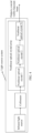
- FIG. 1 is a schematic diagram of a structure of AR glasses according to an embodiment of this application.
- the AR glasses include a holder 134, a light source system 135, a focused photonics component 136, and projection objective lenses 137 and 138.
- the light source system is any one of the following light source systems provided in embodiments of this application, and the light source system 135 is configured to generate a visible Gaussian laser beam.
- the holder 134 is used by a user to wear the AR glasses, the focused photonics component 136 is configured to transmit the visible Gaussian laser beam to the projection objective lenses 137 and 138 through refraction, reflection, or the like, and the projection objective lenses 137 and 138 are configured to transmit the visible Gaussian laser beam to a projection display screen or a display wall.
- the AR glasses may display the image or the pattern on the projection display screen or the display wall.
- FIG. 1 is merely a schematic diagram of a structure of an example of AR glasses provided in this application, and does not constitute any limitation on a structure of the AR glasses provided in this application.
- the structure of the AR glasses provided in this application may include more structural parts. This is not limited in this embodiment of this application.
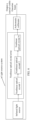
- FIG. 2 is a schematic diagram of a structure of an example of a light source system according to this application.
- the light source system includes: one or more infrared laser light sources, configured to generate infrared lasers.
- the example shown in FIG. 2 shows a schematic diagram of one infrared laser light source.
- a direction shown by arrows in FIG. 2 is a transmission direction of an infrared laser.
- the infrared laser emitted by the infrared laser light source may be used as a pump light source.
- the infrared laser light source may be understood as a pump light source.
- Optical pumping may be understood as a process of using light to make electrons rise (or "be pumped") from a lower energy level to a higher energy level in atoms or molecules.
- the pump light source may be understood as a light source that generates light energy to excite a nonlinear crystal, so that the nonlinear crystal performs wavelength conversion (or frequency conversion) on light exciting the nonlinear crystal.
- This light source may be understood as a pump light source.
- the infrared laser generated by the infrared laser light source may cause electrons in the nonlinear crystal to rise (or "be pumped") from a lower energy level to a higher energy level in atoms or molecules, so that a wavelength or a frequency of the infrared laser can be converted in the nonlinear crystal.
- the infrared laser light source is connected to an input end of a nonlinear optical crystal array, the nonlinear optical crystal array includes one or more nonlinear optical crystals, each nonlinear crystal is configured to perform frequency conversion on the infrared laser and/or spread a wavelength of the infrared laser, and an output end of the nonlinear optical crystal array outputs a visible Gaussian beam.
- power consumption of the used infrared laser light source may be less than or equal to 20 milliwatts (mW).
- the nonlinear optical crystal array includes a plurality of nonlinear optical crystals
- wavelengths of infrared lasers on which any two nonlinear optical crystals perform frequency conversion are different.
- frequencies (or frequency ranges) of infrared lasers on which different nonlinear optical crystals perform frequency conversion are different, in other words, phases of infrared lasers on which different nonlinear optical crystals can perform frequency conversion are different.
- the infrared laser of the wavelength undergoes frequency conversion and forms visible light obtained after the frequency conversion, and another infrared laser that cannot match the phase requirement of the nonlinear optical crystal continues to be transmitted, and undergoes frequency conversion in a nonlinear optical crystal that can match the wavelength.
- Wavelengths of infrared lasers on which different nonlinear optical crystals can perform frequency conversion are different, and each nonlinear optical crystal can output a single-mode Gaussian round spot.
- the infrared laser light source may generate infrared light of wavelengths matching the one or more nonlinear optical crystals for frequency conversion.
- a plurality of laser beams that have undergone frequency conversion may be combined into one coaxial visible Gaussian beam by using the nonlinear optical crystal array.
- a beam output by the output end of the nonlinear optical crystal array is a coaxial visible Gaussian beam
- the coaxial visible Gaussian beam has a round spot, and has relatively high beam quality, and therefore, is helpful for increasing projection display resolution and may be used as a light source of a laser display device.
- the infrared laser light source is used to replace a visible-light semiconductor laser light source to greatly reduce power consumption of the laser light source.
- the light source compared with an EEL, a VCSEL, and the like in the conventional technology, the light source has a simple structure and a smaller volume.
- the infrared laser light source may generate an infrared laser or near infrared (near infra-red, NIR) light of wavelengths matching the one or more nonlinear optical crystals, in other words, a wavelength range of an infrared laser generated by the infrared laser light source includes wavelengths before the one or more nonlinear optical crystals perform frequency conversion.
- the infrared laser light source may be a large-bandwidth pump light source (where for example, a wavelength range is ⁇ ⁇ 150 nm). In this case, the infrared laser light source can match a plurality of different nonlinear optical crystals included in the nonlinear optical crystal array.
- each infrared laser light source may generate an infrared laser or a near infrared laser of a specific wavelength.
- the infrared laser or the near infrared laser of the specific wavelength can match one of the plurality of nonlinear optical crystals, so that the nonlinear optical crystal matching the wavelength can perform frequency conversion on the infrared laser or the near infrared laser of the wavelength.
- the nonlinear optical crystal array includes one or more of a multi-harmonic generation crystal, a sum-frequency crystal, a difference-frequency crystal, an optical parametric generation crystal, an optical parametric amplification crystal, and an optical parametric oscillation crystal.
- the multi-harmonic generation crystal may include one or more of a second harmonic generation crystal, a third harmonic generation crystal, a sum-frequency crystal, and a difference-frequency crystal.
- the second harmonic generation crystal has a second harmonic generation (Second Harmonic generation, SHG) function
- the third harmonic generation crystal has a third harmonic generation (Third Harmonic generation, THG) function
- the sum-frequency crystal has a sum-frequency generation (Sum-Frequency Generation, SFG) function
- the difference-frequency crystal has a difference-frequency generation (Difference-Frequency Generation, DFG) function.
- the second harmonic generation crystal can achieve functions of doubling a frequency and reducing a wavelength by half
- the third harmonic generation crystal can achieve functions of tripling a frequency and reducing a wavelength to one third of an original wavelength.
- Input of the sum-frequency crystal may be two or more laser beams, and a frequency of one laser beam output by the sum-frequency crystal is a sum of frequencies of the two or more laser beams.
- Input of the difference-frequency crystal may be two or more laser beams, and a frequency of one laser beam output by the difference-frequency crystal is a difference between frequencies of the two or more laser beams.
- the optical parametric generation crystal may be a nonlinear optical crystal with an optical parametric generation (Optical Parametric Generation, OPG) function.
- Input of the optical parametric generation crystal may be one laser beam
- output may be a plurality of laser beams
- a sum of frequencies of the plurality of laser beams is a frequency of the input laser beam.
- the optical parametric oscillation generation crystal may be a nonlinear optical crystal with an optical parametric oscillation (optical parametric oscillation, OPO) function, and may convert a laser of one frequency into coherent output of a signal and an idle frequency.
- the optical parametric amplification crystal may be a nonlinear optical crystal with an optical parametric amplification (optical parametric amplification, OPA) function, and may amplify a frequency of a beam of low-frequency light for output.
- the plurality of nonlinear optical crystals include a plurality of multi-harmonic generation crystals.
- the plurality of multi-harmonic generation crystals may include at least two of a red multi-harmonic generation crystal, a blue multi-harmonic generation crystal, and a green multi-harmonic generation crystal.
- the red multi-harmonic generation crystal may multiply a frequency of a laser of a wavelength 1280 nm to generate a red laser of a wavelength 640 nm.
- the green multi-harmonic generation crystal may multiply a frequency of a laser of a wavelength 1064 nm to generate a green laser of a wavelength 532 nm.
- the blue multi-harmonic generation crystal may multiply a frequency of a laser of a wavelength 980 nm to generate a green laser of a wavelength 480 nm.
- the infrared laser light source when there is one infrared laser light source, the infrared laser light source may generate an infrared laser whose wavelength range is 980 nm to 1280 nm, or the infrared laser light source may generate an infrared laser whose wavelength range is 980 nm to 1064 nm.
- a material of the nonlinear optical crystal may be one or more of nonlinear optical crystals such as lithium niobate (LiNbO3, LN), potassium dihydrogen phosphate (KH2PO4, KDP), potassium dideuterium phosphate (KD2PO4, DKDP), lithium iodate (LiIO3, LI), potassium titanium oxide phosphate (KTiOPO4, KTP), beta barium borate ( ⁇ -BaB2O4, BBO), lithium triborate (LiB3O5-LBO), potassium niobate (KNb03, KN), cesium triborate (CSB3O5, CBO), lithium cesium borate (LiCSB6010, CLBO), potassium beryllium fluoroborate (KBe2BO3F2, KBBF), silver gallium sulfide (AgGaS2, AGS), cadmium germanium arsenide (CdGeAs, CGA), and zinc germanium
- nonlinear optical crystals such as
- the infrared laser light source is used to replace a visible-light semiconductor laser light source to greatly reduce power consumption of the laser light source.
- a plurality of nonlinear optical crystals are used to perform frequency conversion and the like on the infrared laser generated by the infrared laser light source to output visible light, and quality of output beams meets Gaussian distribution, so that the quality of the output beams is greatly improved.
- the light source has a simple structure and a small volume, and is easy to package and easy to implement.
- the nonlinear optical crystal array when the nonlinear optical crystal array includes a plurality of nonlinear optical crystals, the plurality of nonlinear optical crystals are connected in series.
- the series connection manner may mean that the plurality of nonlinear optical crystals are arranged in a straight line.
- an output end of the first nonlinear optical crystal is connected to an input end of the second nonlinear optical crystal
- an output end of the second nonlinear optical crystal is connected to an input end of the third nonlinear optical crystal.
- the plurality of nonlinear optical crystals are separately connected by using heads and tails, and the nonlinear optical crystal array has only one input end and one output end as a whole.
- the series connection manner may mean that the plurality of nonlinear optical crystals are distributed in strips.
- the example shown in FIG. 1 is a case in which the plurality of nonlinear optical crystals are distributed in series.
- the plurality of nonlinear optical crystals are connected in series, so that the infrared laser generated by the infrared laser light source can be directly transmitted to the plurality of nonlinear optical crystals in sequence, and therefore the infrared laser can pass through all the nonlinear optical crystals without requiring another optical device to change a transmission path of the infrared light.
- infrared lasers are combined into one visible light by using the nonlinear optical crystal for transmission, so that a completely coaxial visible Gaussian laser beam can be generated.
- a structure is simple and easy to implement, so that complexity of the light source system is further reduced.
- the plurality of nonlinear optical crystals included in the nonlinear optical crystal array may not be connected in series.
- an optical device such as a collimator or a refractor needs to be used to process the infrared laser generated by the infrared laser light source, so that the infrared laser generated by the laser light source can pass through the nonlinear optical crystals in sequence.
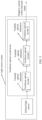
- FIG. 3 shows a light source system including a plurality of infrared laser light sources.
- a direction shown by arrows in FIG. 3 is a transmission direction of an infrared laser.
- the light source system further includes a multi-beam combination module, an input end of the multi-beam combination module is connected to output ends of the plurality of infrared laser light sources, and an output end of the multi-beam combination module is connected to an input end of the nonlinear optical crystal array.
- the multi-beam combination module is configured to: combine infrared lasers emitted by the plurality of infrared laser light sources into one infrared laser beam, and transmit the infrared laser beam to the nonlinear optical crystal array.
- the multi-beam combination module may also be referred to as a multi-pump beam combination module (system).
- the light source system when there is one infrared laser light source, the light source system further includes a collimator, an input end of the collimator is connected to an output end of the infrared laser light source, and an output end of the collimator is connected to an input end of the nonlinear optical crystal array.
- the collimator is configured to: collimate an infrared laser emitted by the infrared laser light source, and transmit the collimated infrared laser to the nonlinear optical crystal array.
- a collimator is connected to the output end of the infrared laser light source.
- the collimator is configured to: perform fast axis collimation on the infrared laser emitted by the infrared laser light source, and input the collimated infrared laser to the nonlinear optical crystal array, to ensure collimation degrees of infrared lasers input to the one or more nonlinear optical crystals, thereby improving infrared laser quality and efficiency of performing frequency conversion by the one or more nonlinear optical crystals.
- the collimator may be a fast axis collimator (fast axis collimator, FAC).
- a variable optical attenuator may be disposed before each nonlinear optical crystal, and the variable optical attenuator is configured to adjust power of an infrared laser of a wavelength corresponding to the nonlinear optical crystal.
- power ratio modulation is performed on infrared lasers input to each nonlinear optical crystal (for example, power ratio modulation is performed on RGB lasers), to control output power of the infrared lasers.
- the variable optical attenuator may be an electrically variable optical attenuator.
- the light source system shown in FIG. 3 or FIG. 4 may also include a plurality of variable optical attenuators.
- antireflection coatings may be further plated on laser input and output end faces of each nonlinear optical crystal, to ensure that a laser in a wavelength range corresponding to the nonlinear optical crystal can completely penetrate the nonlinear optical crystal, thereby improving infrared laser transmission quality and efficiency.
- the laser system further includes an achromatic collimator, an input end of the achromatic collimator is connected to the output end of the nonlinear optical crystal array, and the achromatic collimator is configured to collimate a beam output by the nonlinear optical crystal array, so that quality of a beam output by the light source system can be improved.
- the light source system shown in FIG. 3 , FIG. 4 , or FIG. 5 may also include the achromatic collimator.
- the laser system further includes a filter, the filter is disposed at the output end of the nonlinear optical crystal array, and the filter is configured to: filter the beam output by the nonlinear optical crystal array, and output a filtered beam.
- the light source system shown in FIG. 3 to FIG. 6 may also include the filter.
- the filter may be disposed at an output end of the achromatic collimator.
- FIG. 8 is a schematic diagram of a structure of another example of a light source system according to this application.
- the light source system includes a broadband infrared semiconductor laser die 101, which is an infrared laser light source and is configured to generate a large-bandwidth infrared laser.
- a wavelength range of a generated infrared laser is 980 nm to 1280 nm.
- the infrared semiconductor laser die 101 may be pre-mounted to a carrier base plate 110 through bonding (Die bonding).
- An FAC collimator 102 is connected after the infrared semiconductor laser die 101, and is configured to perform fast axis collimation on an infrared laser.
- An output end of the FAC collimator 102 is connected to an input end of a red multi-harmonic generation crystal 103, an output end of the red multi-harmonic generation crystal 103 is connected to an input end of a green multi-harmonic generation crystal 104, and an output end of the green multi-harmonic generation crystal 104 is connected to an input end of a blue multi-harmonic generation crystal 105.
- the three multi-harmonic generation crystals constitute a nonlinear optical crystal array, and the three multi-harmonic generation crystals are arranged on the carrier base plate 110 in one row.
- Electrically variable optical attenuators 107, 108, and 109 are sandwiched between different multi-harmonic generation crystals, and are separately configured to adjust infrared lasers input to different multi-harmonic generation crystals.
- An achromatic collimator 106 is connected to an output end of the blue multi-harmonic generation crystal 105, and is configured to collimate a beam output by the blue multi-harmonic generation crystal 105, so that the achromatic collimator 106 can output a parallel beam 112.
- An output end of the achromatic collimator 106 is connected to an input end of a filter 113.
- the filter 113 may filter out excess infrared pump light in the parallel beam 112, and then a visible combined parallel RGB beam is output from a light outlet of the light source system.
- the light source system may be passively packaged in a package 111.
- the broadband infrared laser light source 101 on which the FAC collimator 102 performs fast axis collimation outputs an infrared laser (a pump laser) whose wavelength range is 980 nm to 1280 nm.
- the red multi-harmonic generation crystal 103 multiplies a frequency of an infrared laser of a wavelength 1280 nm to generate a red laser of a wavelength 640 nm.
- antireflection coatings of a wavelength range 980 nm to 1070 nm may be plated on two ends of the red multi-harmonic generation crystal 103, to ensure that an infrared laser in the wavelength range can completely penetrate the red multi-harmonic generation crystal 103.
- a pump laser output by the red multi-harmonic generation crystal 103 reaches the green multi-harmonic generation crystal 104, a frequency of an infrared laser of a wavelength 1064 nm is multiplied to generate a green laser of a wavelength 532 nm.
- antireflection coatings of wavelengths 640 nm and 980 nm are plated on two ends of the green multi-harmonic generation crystal 104, to ensure that lasers of the wavelengths can completely penetrate the green multi-harmonic generation crystal 104.
- a pump laser output by the green multi-harmonic generation crystal 104 reaches the blue multi-harmonic generation crystal 105, a frequency of a laser of a wavelength 980 nm is multiplied to generate a blue laser of a wavelength 490 nm.
- antireflection coatings of wavelengths 640 nm and 532 nm are plated on two ends of the blue multi-harmonic generation crystal 105, to ensure that lasers of the wavelengths can completely penetrate the blue multi-harmonic generation crystal 105.
- a frequency-multiplied RGB laser can be output at the output end of the blue multi-harmonic generation crystal 105, then the achromatic collimator 106 collimates the frequency-multiplied RGB laser beam, then the filter 113 filters out excess infrared pump light, and a visible combined RGB beam is output from the light outlet of the light source system.
- the light source system used for display needs to perform power ratio modulation on RGB lasers.
- the electrically variable optical attenuator 107, 108, and 109 may be separately added before the three multi-harmonic generation crystals, and are respectively used to control output power of infrared lasers of wavelengths 1280 nm, 1064 nm, and 980 nm, so that output power of the RGB lasers is controlled.
- the infrared laser die and the plurality of multi-harmonic generation crystals may be first passively mounted to the carrier base plate, then the FAC collimator and the achromatic collimator may be actively assembled to the carrier base plate, and the package is finally passively packaged, so that a packaging architecture is greatly simplified, and packaging can be completed only through micrometer ( ⁇ m)-level passive mounting (mounting of the infrared laser die and mounting of the multi-harmonic generation crystals) and micrometer-level passive mounting (packaging of the FAC collimator and the achromatic collimator) processes, thereby greatly reducing packaging costs and increasing packaging efficiency and a yield rate.
- micrometer ( ⁇ m)-level passive mounting mounting of the infrared laser die and mounting of the multi-harmonic generation crystals
- micrometer-level passive mounting packaging of the FAC collimator and the achromatic collimator
- the nonlinear multi-harmonic generation crystal can output a single-mode Gaussian beam, and an output spot is round. This is quite helpful for increasing projection display resolution.
- only two multi-harmonic generation crystals may be used.
- only the blue light multi-harmonic generation crystal and the green multi-harmonic generation crystal are integrated.
- a wavelength range of an infrared laser output by the infrared semiconductor laser die may be 980 nm to 1064 nm, and a beam output by the light source system includes only a combined beam of blue and green.
- a plurality of infrared semiconductor laser dies may be alternatively used to generate a plurality of infrared lasers of different wavelengths, and a beam combination system may be used to combine the plurality of infrared lasers of different wavelengths and then transmit one combined beam to one or more nonlinear crystals for frequency conversion.
- a near infrared laser light source may be used to replace the infrared laser light source to generate a near infrared laser.
- a plurality of near infrared pump light sources may be used to generate near infrared lasers, and a beam combination system may be used to combine the plurality of near infrared lasers of different wavelengths and then transmit one combined beam to one or more nonlinear crystals for frequency conversion.
Landscapes
- Physics & Mathematics (AREA)
- Nonlinear Science (AREA)
- General Physics & Mathematics (AREA)
- Optics & Photonics (AREA)
- Chemical & Material Sciences (AREA)
- Crystallography & Structural Chemistry (AREA)
- Condensed Matter Physics & Semiconductors (AREA)
- Electromagnetism (AREA)
- Optical Modulation, Optical Deflection, Nonlinear Optics, Optical Demodulation, Optical Logic Elements (AREA)
- Semiconductor Lasers (AREA)
Applications Claiming Priority (2)
| Application Number | Priority Date | Filing Date | Title |
|---|---|---|---|
| CN202010491313.7A CN113759644B (zh) | 2020-06-02 | 2020-06-02 | 光源系统以及激光投影显示设备 |
| PCT/CN2021/097365 WO2021244488A1 (zh) | 2020-06-02 | 2021-05-31 | 光源系统以及激光投影显示设备 |
Publications (3)
| Publication Number | Publication Date |
|---|---|
| EP4152092A1 true EP4152092A1 (de) | 2023-03-22 |
| EP4152092A4 EP4152092A4 (de) | 2023-11-08 |
| EP4152092B1 EP4152092B1 (de) | 2026-02-25 |
Family
ID=78782983
Family Applications (1)
| Application Number | Title | Priority Date | Filing Date |
|---|---|---|---|
| EP21817854.9A Active EP4152092B1 (de) | 2020-06-02 | 2021-05-31 | Lichtquellensystem und laserprojektionsanzeigevorrichtung |
Country Status (5)
| Country | Link |
|---|---|
| US (1) | US20230105608A1 (de) |
| EP (1) | EP4152092B1 (de) |
| JP (1) | JP7564246B2 (de) |
| CN (1) | CN113759644B (de) |
| WO (1) | WO2021244488A1 (de) |
Families Citing this family (2)
| Publication number | Priority date | Publication date | Assignee | Title |
|---|---|---|---|---|
| WO2025125176A2 (en) * | 2023-12-15 | 2025-06-19 | University Of Southampton | Optical apparatus |
| CN119535796B (zh) * | 2024-12-13 | 2025-09-23 | 歌尔光学科技有限公司 | 衍射光学结构、扩大fov的方法、光学系统及智能头戴设备 |
Family Cites Families (14)
| Publication number | Priority date | Publication date | Assignee | Title |
|---|---|---|---|---|
| DE19504047C1 (de) * | 1995-02-08 | 1996-07-25 | Daimler Benz Ag | Lasersystem für Farbbildprojektion |
| US6480325B1 (en) * | 2000-05-25 | 2002-11-12 | The Board Of Trustees Of The Leland Stanford Junior University | Laser light source and image display based on quasi-phasematched nonlinear optical devices |
| CN100432821C (zh) * | 2004-07-15 | 2008-11-12 | 松下电器产业株式会社 | 相干光源和使用该光源的光学装置 |
| CN100394652C (zh) * | 2005-01-17 | 2008-06-11 | 南京大学 | 以级联超晶格为变频晶体的全固态准白光激光器的设置方法 |
| CN100490496C (zh) * | 2005-07-15 | 2009-05-20 | 天津大学 | 激光彩色电视显示红绿蓝激光的发生方法及装置 |
| JP4855401B2 (ja) * | 2005-07-28 | 2012-01-18 | パナソニック株式会社 | 波長変換素子、レーザ光源装置、2次元画像表示装置及びレーザ加工装置 |
| KR20080077629A (ko) * | 2005-12-20 | 2008-08-25 | 코닌클리케 필립스 일렉트로닉스 엔.브이. | 레이저 피코-빔머에 대한 최적 칼라 |
| CN1900805A (zh) * | 2006-07-25 | 2007-01-24 | 南京大学 | 红绿蓝彩色激光显示光源的制备方法 |
| CN101646976B (zh) * | 2007-03-22 | 2012-09-26 | 松下电器产业株式会社 | 激光波长转换装置以及具备该激光波长转换装置的图像显示装置 |
| JP2010204197A (ja) * | 2009-02-27 | 2010-09-16 | Sony Corp | レーザ装置、レーザディスプレイ装置、レーザ照射装置及び非線形光学素子 |
| JP2011154275A (ja) * | 2010-01-28 | 2011-08-11 | Nec Corp | 分極反転波長変換素子および光源 |
| US9509112B2 (en) * | 2013-06-11 | 2016-11-29 | Kla-Tencor Corporation | CW DUV laser with improved stability |
| JP2016177057A (ja) * | 2015-03-19 | 2016-10-06 | 株式会社ニコン | 光源装置、計測装置及びエンコーダ装置 |
| CN106992429A (zh) * | 2017-06-07 | 2017-07-28 | 中科和光(天津)应用激光技术研究所有限公司 | 一种结构紧凑的高效率级联倍频激光器 |
-
2020
- 2020-06-02 CN CN202010491313.7A patent/CN113759644B/zh active Active
-
2021
- 2021-05-31 WO PCT/CN2021/097365 patent/WO2021244488A1/zh not_active Ceased
- 2021-05-31 EP EP21817854.9A patent/EP4152092B1/de active Active
- 2021-05-31 JP JP2022574283A patent/JP7564246B2/ja active Active
-
2022
- 2022-11-30 US US18/060,489 patent/US20230105608A1/en active Pending
Also Published As
| Publication number | Publication date |
|---|---|
| CN113759644B (zh) | 2022-12-27 |
| EP4152092B1 (de) | 2026-02-25 |
| CN113759644A (zh) | 2021-12-07 |
| JP2023528429A (ja) | 2023-07-04 |
| JP7564246B2 (ja) | 2024-10-08 |
| WO2021244488A1 (zh) | 2021-12-09 |
| US20230105608A1 (en) | 2023-04-06 |
| EP4152092A4 (de) | 2023-11-08 |
Similar Documents
| Publication | Publication Date | Title |
|---|---|---|
| US8126025B2 (en) | Laser light source apparatus, and monitoring apparatus and image display apparatus using the same | |
| TWI481137B (zh) | 變頻式脈衝雷射光源 | |
| US12334715B2 (en) | Visible light source including integrated VCSELs and integrated photonic cavities | |
| US20230105608A1 (en) | Light source system and laser projection display device | |
| KR101217557B1 (ko) | 직접 광변조가 가능한 레이저 모듈 및 이를 채용한 레이저디스플레이 장치 | |
| US20060233206A1 (en) | Frequency doubling crystal and frequency doubled external cavity laser | |
| US8306075B2 (en) | System and method for optical frequency conversion | |
| US11825244B2 (en) | Planar light circuit and arrangement with planar light circuit | |
| US20080259436A1 (en) | Laser light source device, illumination device, image display device, and monitor | |
| US20060083284A1 (en) | Method for increasing the dynamic range of a cavity enhanced optical spectrometer | |
| US7489437B1 (en) | Fiber laser red-green-blue (RGB) light source | |
| JP5156015B2 (ja) | コンパクトな多色光線源 | |
| JP2008177473A (ja) | レーザ光源装置およびそれを用いたモニタ装置ならびに画像表示装置 | |
| US7817334B2 (en) | Wavelength conversion element, light source device, image display device, and monitor device | |
| JP2015510273A (ja) | レーザアーキテクチャ | |
| JP2676743B2 (ja) | 導波路型波長変換素子 | |
| US7561612B2 (en) | Laser source device, image display device equipped with the laser source device, and monitor device | |
| WO2007072410A2 (en) | Optimal colors for a laser pico-beamer | |
| US20160126691A1 (en) | Visible wideband laser for flat panel display illumination | |
| US20170054267A1 (en) | Visible wideband laser for flat panel display illumination | |
| JP2009117573A (ja) | 光源装置、プロジェクタ、及びモニタ装置 |
Legal Events
| Date | Code | Title | Description |
|---|---|---|---|
| STAA | Information on the status of an ep patent application or granted ep patent |
Free format text: STATUS: THE INTERNATIONAL PUBLICATION HAS BEEN MADE |
|
| PUAI | Public reference made under article 153(3) epc to a published international application that has entered the european phase |
Free format text: ORIGINAL CODE: 0009012 |
|
| STAA | Information on the status of an ep patent application or granted ep patent |
Free format text: STATUS: REQUEST FOR EXAMINATION WAS MADE |
|
| 17P | Request for examination filed |
Effective date: 20221216 |
|
| AK | Designated contracting states |
Kind code of ref document: A1 Designated state(s): AL AT BE BG CH CY CZ DE DK EE ES FI FR GB GR HR HU IE IS IT LI LT LU LV MC MK MT NL NO PL PT RO RS SE SI SK SM TR |
|
| DAV | Request for validation of the european patent (deleted) | ||
| DAX | Request for extension of the european patent (deleted) | ||
| A4 | Supplementary search report drawn up and despatched |
Effective date: 20231005 |
|
| RIC1 | Information provided on ipc code assigned before grant |
Ipc: H01S 5/06 20060101ALI20230929BHEP Ipc: G03B 21/20 20060101AFI20230929BHEP |
|
| GRAP | Despatch of communication of intention to grant a patent |
Free format text: ORIGINAL CODE: EPIDOSNIGR1 |
|
| STAA | Information on the status of an ep patent application or granted ep patent |
Free format text: STATUS: GRANT OF PATENT IS INTENDED |
|
| RIC1 | Information provided on ipc code assigned before grant |
Ipc: G03B 21/20 20060101AFI20250915BHEP Ipc: H01S 5/06 20060101ALI20250915BHEP |
|
| INTG | Intention to grant announced |
Effective date: 20251016 |
|
| GRAS | Grant fee paid |
Free format text: ORIGINAL CODE: EPIDOSNIGR3 |
|
| GRAA | (expected) grant |
Free format text: ORIGINAL CODE: 0009210 |
|
| STAA | Information on the status of an ep patent application or granted ep patent |
Free format text: STATUS: THE PATENT HAS BEEN GRANTED |
|
| AK | Designated contracting states |
Kind code of ref document: B1 Designated state(s): AL AT BE BG CH CY CZ DE DK EE ES FI FR GB GR HR HU IE IS IT LI LT LU LV MC MK MT NL NO PL PT RO RS SE SI SK SM TR |
|
| REG | Reference to a national code |
Ref country code: CH Ref legal event code: F10 Free format text: ST27 STATUS EVENT CODE: U-0-0-F10-F00 (AS PROVIDED BY THE NATIONAL OFFICE) Effective date: 20260225 Ref country code: GB Ref legal event code: FG4D |
|
| REG | Reference to a national code |
Ref country code: DE Ref legal event code: R096 Ref document number: 602021048797 Country of ref document: DE |
|
| REG | Reference to a national code |
Ref country code: IE Ref legal event code: FG4D |