EP4151801A1 - Vorrichtung und system zur erkennung eines strassenoberflächenzustands und verfahren zur erkennung eines strassenoberflächenzustands unter verwendung davon - Google Patents
Vorrichtung und system zur erkennung eines strassenoberflächenzustands und verfahren zur erkennung eines strassenoberflächenzustands unter verwendung davon Download PDFInfo
- Publication number
- EP4151801A1 EP4151801A1 EP21803739.8A EP21803739A EP4151801A1 EP 4151801 A1 EP4151801 A1 EP 4151801A1 EP 21803739 A EP21803739 A EP 21803739A EP 4151801 A1 EP4151801 A1 EP 4151801A1
- Authority
- EP
- European Patent Office
- Prior art keywords
- road surface
- surface condition
- road
- sound signal
- detection apparatus
- Prior art date
- Legal status (The legal status is an assumption and is not a legal conclusion. Google has not performed a legal analysis and makes no representation as to the accuracy of the status listed.)
- Pending
Links
Images




Classifications
-
- G—PHYSICS
- G08—SIGNALLING
- G08G—TRAFFIC CONTROL SYSTEMS
- G08G1/00—Traffic control systems for road vehicles
- G08G1/09—Arrangements for giving variable traffic instructions
- G08G1/091—Traffic information broadcasting
- G08G1/093—Data selection, e.g. prioritizing information, managing message queues, selecting the information to be output
-
- E—FIXED CONSTRUCTIONS
- E01—CONSTRUCTION OF ROADS, RAILWAYS, OR BRIDGES
- E01F—ADDITIONAL WORK, SUCH AS EQUIPPING ROADS OR THE CONSTRUCTION OF PLATFORMS, HELICOPTER LANDING STAGES, SIGNS, SNOW FENCES, OR THE LIKE
- E01F9/00—Arrangement of road signs or traffic signals; Arrangements for enforcing caution
- E01F9/40—Arrangements responsive to adverse atmospheric conditions, e.g. to signal icy roads or to automatically illuminate in fog; Arrangements characterised by heating or drying means
-
- E—FIXED CONSTRUCTIONS
- E01—CONSTRUCTION OF ROADS, RAILWAYS, OR BRIDGES
- E01C—CONSTRUCTION OF, OR SURFACES FOR, ROADS, SPORTS GROUNDS, OR THE LIKE; MACHINES OR AUXILIARY TOOLS FOR CONSTRUCTION OR REPAIR
- E01C23/00—Auxiliary devices or arrangements for constructing, repairing, reconditioning, or taking-up road or like surfaces
- E01C23/01—Devices or auxiliary means for setting-out or checking the configuration of new surfacing, e.g. templates, screed or reference line supports; Applications of apparatus for measuring, indicating, or recording the surface configuration of existing surfacing, e.g. profilographs
-
- G—PHYSICS
- G01—MEASURING; TESTING
- G01S—RADIO DIRECTION-FINDING; RADIO NAVIGATION; DETERMINING DISTANCE OR VELOCITY BY USE OF RADIO WAVES; LOCATING OR PRESENCE-DETECTING BY USE OF THE REFLECTION OR RERADIATION OF RADIO WAVES; ANALOGOUS ARRANGEMENTS USING OTHER WAVES
- G01S1/00—Beacons or beacon systems transmitting signals having a characteristic or characteristics capable of being detected by non-directional receivers and defining directions, positions, or position lines fixed relatively to the beacon transmitters; Receivers co-operating therewith
- G01S1/72—Beacons or beacon systems transmitting signals having a characteristic or characteristics capable of being detected by non-directional receivers and defining directions, positions, or position lines fixed relatively to the beacon transmitters; Receivers co-operating therewith using ultrasonic, sonic or infrasonic waves
- G01S1/74—Details
- G01S1/75—Transmitters
- G01S1/751—Mounting or deployment thereof
-
- G—PHYSICS
- G06—COMPUTING OR CALCULATING; COUNTING
- G06Q—INFORMATION AND COMMUNICATION TECHNOLOGY [ICT] SPECIALLY ADAPTED FOR ADMINISTRATIVE, COMMERCIAL, FINANCIAL, MANAGERIAL OR SUPERVISORY PURPOSES; SYSTEMS OR METHODS SPECIALLY ADAPTED FOR ADMINISTRATIVE, COMMERCIAL, FINANCIAL, MANAGERIAL OR SUPERVISORY PURPOSES, NOT OTHERWISE PROVIDED FOR
- G06Q50/00—Information and communication technology [ICT] specially adapted for implementation of business processes of specific business sectors, e.g. utilities or tourism
- G06Q50/40—Business processes related to the transportation industry
-
- G—PHYSICS
- G08—SIGNALLING
- G08G—TRAFFIC CONTROL SYSTEMS
- G08G1/00—Traffic control systems for road vehicles
- G08G1/01—Detecting movement of traffic to be counted or controlled
- G08G1/0104—Measuring and analyzing of parameters relative to traffic conditions
- G08G1/0108—Measuring and analyzing of parameters relative to traffic conditions based on the source of data
- G08G1/0116—Measuring and analyzing of parameters relative to traffic conditions based on the source of data from roadside infrastructure, e.g. beacons
-
- G—PHYSICS
- G08—SIGNALLING
- G08G—TRAFFIC CONTROL SYSTEMS
- G08G1/00—Traffic control systems for road vehicles
- G08G1/01—Detecting movement of traffic to be counted or controlled
- G08G1/0104—Measuring and analyzing of parameters relative to traffic conditions
- G08G1/0125—Traffic data processing
- G08G1/0133—Traffic data processing for classifying traffic situation
-
- G—PHYSICS
- G08—SIGNALLING
- G08G—TRAFFIC CONTROL SYSTEMS
- G08G1/00—Traffic control systems for road vehicles
- G08G1/01—Detecting movement of traffic to be counted or controlled
- G08G1/048—Detecting movement of traffic to be counted or controlled with provision for compensation of environmental or other condition, e.g. snow, vehicle stopped at detector
-
- G—PHYSICS
- G08—SIGNALLING
- G08G—TRAFFIC CONTROL SYSTEMS
- G08G1/00—Traffic control systems for road vehicles
- G08G1/01—Detecting movement of traffic to be counted or controlled
- G08G1/052—Detecting movement of traffic to be counted or controlled with provision for determining speed or overspeed
-
- G—PHYSICS
- G08—SIGNALLING
- G08G—TRAFFIC CONTROL SYSTEMS
- G08G1/00—Traffic control systems for road vehicles
- G08G1/09—Arrangements for giving variable traffic instructions
- G08G1/0962—Arrangements for giving variable traffic instructions having an indicator mounted inside the vehicle, e.g. giving voice messages
- G08G1/0967—Systems involving transmission of highway information, e.g. weather, speed limits
-
- G—PHYSICS
- G08—SIGNALLING
- G08G—TRAFFIC CONTROL SYSTEMS
- G08G1/00—Traffic control systems for road vehicles
- G08G1/09—Arrangements for giving variable traffic instructions
- G08G1/0962—Arrangements for giving variable traffic instructions having an indicator mounted inside the vehicle, e.g. giving voice messages
- G08G1/0967—Systems involving transmission of highway information, e.g. weather, speed limits
- G08G1/096766—Systems involving transmission of highway information, e.g. weather, speed limits where the system is characterised by the origin of the information transmission
- G08G1/096783—Systems involving transmission of highway information, e.g. weather, speed limits where the system is characterised by the origin of the information transmission where the origin of the information is a roadside individual element
-
- E—FIXED CONSTRUCTIONS
- E01—CONSTRUCTION OF ROADS, RAILWAYS, OR BRIDGES
- E01H—STREET CLEANING; CLEANING OF PERMANENT WAYS; CLEANING BEACHES; DISPERSING OR PREVENTING FOG IN GENERAL CLEANING STREET OR RAILWAY FURNITURE OR TUNNEL WALLS
- E01H10/00—Improving gripping of ice-bound or other slippery traffic surfaces, e.g. using gritting or thawing materials ; Roadside storage of gritting or solid thawing materials; Permanently installed devices for applying gritting or thawing materials; Mobile apparatus specially adapted for treating wintry roads by applying liquid, semi-liquid or granular materials
- E01H10/005—Permanently-installed devices for applying gritting or thawing materials, e.g. for spreading grit, for spraying de-icing liquids
-
- G—PHYSICS
- G01—MEASURING; TESTING
- G01S—RADIO DIRECTION-FINDING; RADIO NAVIGATION; DETERMINING DISTANCE OR VELOCITY BY USE OF RADIO WAVES; LOCATING OR PRESENCE-DETECTING BY USE OF THE REFLECTION OR RERADIATION OF RADIO WAVES; ANALOGOUS ARRANGEMENTS USING OTHER WAVES
- G01S2201/00—Indexing scheme relating to beacons or beacon systems transmitting signals capable of being detected by non-directional receivers and defining directions, positions, or position lines fixed relatively to the beacon transmitters
- G01S2201/01—Indexing scheme relating to beacons or beacon systems transmitting signals capable of being detected by non-directional receivers and defining directions, positions, or position lines fixed relatively to the beacon transmitters adapted for specific applications or environments
-
- G—PHYSICS
- G08—SIGNALLING
- G08G—TRAFFIC CONTROL SYSTEMS
- G08G1/00—Traffic control systems for road vehicles
- G08G1/20—Monitoring the location of vehicles belonging to a group, e.g. fleet of vehicles, countable or determined number of vehicles
- G08G1/202—Dispatching vehicles on the basis of a location, e.g. taxi dispatching
Definitions
- the present invention relates to a road surface condition detection apparatus, and more particularly, to a road surface condition detection apparatus and system for determining a road surface condition through a sound signal, and a road surface condition detection method using the same.
- Black ice refers to a thin layer of snow or rain that seeps into the cracks of the asphalt road during the day, mixes with road oil and dust, and freezes thinly on the road at night.
- Black ice is often seen as a major cause of traffic accidents, as it is less conspicuous when driving on the road and is easy to just assume that the road is a little wet.
- Korean Patent Publication No. 10-2019-0140272 discloses an "apparatus and method for sensing black ice”.
- the disclosed black ice sensing apparatus is equipped in a vehicle to sense black ice.
- This apparatus includes a sensing unit for measuring a road surface temperature and an ambient temperature, a control unit for determining the existence of black ice by using the road surface temperature and the ambient temperature, and a communication unit for transmits black ice information to a navigation device when the control unit determines that there is black ice.
- black ice can be detected.
- a sensing range is only a few meters in front of a driving vehicle, there is a problem in that the time for a driver to actually respond to a danger is short.
- ABS anti-lock brake system
- the present invention is intended to provide an apparatus and system for detecting a road surface condition and a method for detecting a road surface condition using the same, which can determine the road surface condition of a specific section from a remote location and thereby quickly and accurately take measures corresponding to the road surface condition.
- the controller may learn road surface conditions depending on sound signals measured by the sensor unit and determine the road surface condition through stored learning data.
- the controller may filter a background value and noise from the sound signal measured by the sensor unit and determine the road surface condition based on a frequency range configured for each road surface condition.
- the sensor unit may measure a road surface temperature, ambient temperature, and humidity.
- the controller may determine the road surface condition through the sound signal, calculate a dew point through the surface temperature and humidity measured by the sensor unit, and apply the calculated dew point and the ambient temperature to determining the road surface condition.
- the controller may determine that the road surface is icy when the calculated dew point exceeds a predetermined value and when the ambient temperature is lower than a predetermined value.
- the controller may determine a pot hole, a crash, or a skid through the sound signal measured by the sensor unit.
- a system for detecting a road surface condition may include a road surface condition detection apparatus installed on a road and measuring a sound signal generated according to a movement of a moving object on the road; and a management server receiving the sound signal from the road surface condition detection apparatus, distinguishing the sound signal as a normal state or an abnormal state, and determining, in case of the abnormal state, the road surface condition including at least one of wet, icy, slush, and snowy conditions.
- the road surface condition detection apparatus may be provided as a plurality of road surface condition detection apparatuses installed to be spaced apart from each other at regular intervals on the road.
- the management server may calculate a speed of the moving object based on a predetermined distance between the road surface condition detection apparatuses and by measuring a passing time of the moving object from the sound signal measured by the road surface condition detection apparatus.
- the management server may determine a range of the road surface condition, based on whether road surface conditions determined from adjacent road surface condition detection apparatuses overlap with each other.
- the management server may output the determined road surface condition through an electronic road sign (VMS, variable message signs) or operate a snow removal device installed at a corresponding location relying on the determined road surface condition.
- VMS electronic road sign
- variable message signs variable message signs
- a method for detecting a road surface condition may include, by a road surface condition detection apparatus installed on a road, measuring a sound signal generated according to a movement of a moving object on the road; by the road surface condition detection apparatus, distinguishing the measured sound signal as a normal state or an abnormal state; and by the road surface condition detection apparatus, determining, in case of the abnormal state, the road surface condition including at least one of wet, icy, slush, and snowy conditions.
- a method for detecting a road surface condition may include, by a management server, receiving, from a road surface condition detection apparatus installed on a road, a sound signal generated according to a movement of a moving object on the road; by the management server, distinguishing the sound signal as a normal state or an abnormal state; and by the management server, determining, in case of the abnormal state, the road surface condition including at least one of wet, icy, slush, and snowy conditions.
- the road surface condition detection apparatus can determine a road surface condition including at least one of wet, icy, slush, and snowy conditions through a sound signal, thereby quickly and accurately taking measures corresponding to the road surface condition of a specific section from a remote location without a shaded area due to its wide coverage.
- the element when it is stated that a certain element is “coupled to” or “connected to” another element, the element may be logically or physically coupled or connected to another element. That is, the element may be directly coupled or connected to another element, or a new element may exist between both elements.
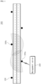
- FIG. 1 is a diagram illustrating a road surface condition detection system according to an embodiment of the present invention.
- the road surface condition detection apparatus 100 may be disposed to be spaced apart from each other at regular intervals on the road.
- the road surface condition detection apparatus 100 may be arranged in a zigzag manner at both sides of the road or arranged in a line at one side.
- the road surface condition detection apparatus 100 may be installed at intervals of 100 meters in a section vulnerable to freezing or at intervals of 80 meters in a section vulnerable to freezing near a steep slope or a sharp curve.
- the road surface condition detection apparatus 100 measures a sound signal generated according to the movement of a moving object on the road in real time.
- the moving object may be representatively, but is not limited to, a vehicle.
- the road surface condition detection apparatus 100 itself may measure a sound signal and determine a road surface condition based on the measured sound signal.
- the configuration of the apparatus becomes complicated and each road surface condition detection apparatus 100 has to store a large amount of data.
- the road surface condition detection apparatus 100 collects sound signals according to the movement of a moving object and transmits the collected sound signals to the management server 200 in real time.
- the management server 200 has an ID of each road surface condition detection apparatus 100 and also has a reference value for each road surface condition detection apparatus 100, that is, a frequency spectrum of a sound when driving on a dry road.
- the management server 200 may distinguish the sound signal as a normal state or an abnormal state. That is, the management server 200 may primarily determine whether the road surface is in a normal state or an abnormal state.
- the management server 200 determines the road surface condition including at least one of wet, icy, slush, and snowy conditions.
- the management server 200 learns road surface conditions depending on measured sound signals and determines a road surface condition through stored learning data.
- the management server 200 may output the determined road surface condition through an electronic road sign (VMS, variable message signs) or operate a snow removal device installed at a corresponding location relying on the determined road surface condition.
- VMS electronic road sign
- the management server 200 may operate in conjunction with a control system for managing and monitoring a road state or be installed in the control system, and may automatically expose an abnormal road condition and location on a screen.
- the control system may output a warning message through the electronic road sign, spray salt water or calcium chloride through a snow removal device installed on the road, or dispatches a tow vehicle in case of an accident.
- the management server 200 may calculate a speed of a moving object based on a predetermined distance between the road surface condition detection apparatuses 100 and by measuring a passing time of the moving object from the sound signal measured by the road surface condition detection apparatus 100. That is, the management server 200 may determine a peak value of the sound signal measured by each road condition detection apparatus 100 as the passing time of the moving object and calculate the speed of the moving object by measuring the passing times of the road surface condition detection apparatuses 100. The measured speed may be used to crack down on the over-speed of a moving object in conjunction with a camera installed on the road. In this way, it is possible to reduce the cost of over-speed measuring equipment buried in the road. Meanwhile, although it has been described that the management server 200 performs the function of measuring the speed of the moving object, this is not a limitation. Alternatively, the road surface condition detection apparatus 100 by itself may measure the speed of the moving object through mutual communication and operate in conjunction with the camera.
- the management server 200 may determine the range of a road surface condition, based on whether road surface conditions determined from adjacent road surface condition detection apparatuses 100 overlap with each other. For example, when it is determined that the road surface conditions corresponding to a first road surface condition detection apparatus 100a and a second road surface condition detection apparatus 100b are icy, the management server 200 may determine a section between the first and second road surface condition detection apparatuses 100a and 100b as an icy section.
- the road surface condition detection system 300 can determine a road surface condition including at least one of wet, icy, slush, and snowy conditions through a sound signal, thereby quickly and accurately taking measures corresponding to the road surface condition of a specific section from a remote location without a shaded area due to its wide coverage.
- FIG. 2 is a block diagram illustrating the configuration of a road surface condition detection apparatus according to an embodiment of the present invention.
- the road surface condition detection apparatus 100 is configured to include a communication unit 110, a sensor unit 130, a storage unit 150, a power supply unit 170, and a controller 190.
- the communication unit 110 transmits and receives data with the management server 200 or between respective components in the road surface condition detection apparatus 100.
- the communication unit 110 may transmit a sound signal measured by the sensor unit 130 to the controller 170 or the management server 200 and, in case where the road surface condition detection apparatus 100 itself analyzes the sound signal, transmit an analysis result (i.e., information on a current road surface condition) to the management server 200.
- the communication unit 110 may receive the sound signal from the sensor unit 130 or transmit the sound signal to the management server 200 through long range (LoRa) communication, long term evolution (LTE) communication, 5G communication, or the like.
- the communication unit 110 may include a modem that modulates a signal to be transmitted and demodulates a received signal.
- the sensor unit 130 may measure a sound signal as a moving object moves on a road.
- the sensor unit 130 may be a non-directional high-sensitivity microphone for measuring a sound signal.
- the sensor unit 130 may include a temperature sensor for measuring an ambient temperature, a humidity sensor for measuring an ambient humidity, and an infrared (IR) surface temperature sensor for measuring a road surface temperature.
- the sensor unit 130 may transmit the measured sound signal, ambient temperature, ambient humidity, and road surface temperature to the controller 170 in real time.
- the sensor unit 130 may be installed separately from the controller 170 or formed integrally with the controller 170.
- the controller 170 may be configured to cover a plurality of sensor units 130 through the communication unit 110, and one controller 170 may be configured to collect sound signals, ambient temperatures, ambient humidity, and road surface temperatures from the plurality of sensor units 130.
- one sensor unit 130 may be integrally formed with one controller 170.
- the storage unit 150 stores a program and data necessary for the functional operation of the road surface condition detection apparatus 100.
- the storage unit 150 may store an algorithm for distinguishing a sound signal measured by the sensor unit 130 as a normal state or an abnormal state.
- the algorithm for distinguishing a sound signal as a normal or abnormal state may be a generative model.
- the storage unit 150 may store an algorithm for determining a road surface condition including wet, icy, slush, and snowy conditions in case of an abnormal state.
- the algorithm for determining the road surface condition may be a discriminative model.
- the power supply unit 170 supplies power according to the functional operation of the road surface condition detection apparatus 100.
- the power supply unit 170 may be configured to receive commercial power, or to generate power by itself by having a solar panel and a battery.
- the controller 190 controls the overall functional operation of the road surface condition detection apparatus 100.
- the controller 190 may include a primary determination module 191 and a secondary determination module 192.
- the primary determination module 191 distinguishes a sound signal measured by the sensor unit 130 as a normal state or an abnormal state.
- the controller 190 may determine a normal or abnormal state through the generative model stored in the storage unit 150 and learn the result.
- FIGS. 6 and 7 are graphs illustrating frequency characteristics of sound signals depending on road surface conditions.
- FIG. 6 is a graph showing the frequency characteristics according to the movement of a vehicle on a clear day
- FIG. 7 is a graph showing the frequency characteristics according to the movement of the same vehicle at the same location as FIG. 6 on a rainy day.
- the graph of FIG. 6 shows a small difference between the value (a) when there is no vehicle and the value (b) when a vehicle is moving
- the graph of FIG. 7 shows a significant difference between the value (a) when there is no vehicle and the value (b) when a vehicle is moving, compared to the graph of FIG. 6 .
- the primary determination module 191 may determine a normal state or an abnormal state through a difference in frequency between the normal state and the abnormal state.
- the secondary determination module 192 determines a road surface condition including at least one of wet, icy, slush, and snowy conditions in case of the abnormal state.
- the secondary determination module 192 may filter a background value and noise from the sound signal measured by the sensor unit 130, and then determine the road surface condition based on a frequency range configured for each road surface condition. In this case, the secondary determination module 192 may determine the road surface condition through the discriminative model and learn the determination result.
- the secondary determination module 192 may determine the road surface condition in real time based on each moving object and finally determine the corresponding road surface condition when the road surface conditions for a predetermined number of moving objects match. That is, instead of transmitting the determination result for one moving object to the management server 200 in real time, the secondary determination module 192 may accumulates the determination results for a predetermined number of moving objects and, when the accumulated determination results match, notify the corresponding road surface condition to the management server 200, thereby increasing accuracy.
- the secondary determination module 192 may not only determine the road surface condition through the sound signal, but also calculate the dew point through the surface temperature and humidity measured by the sensor unit 130 and apply the calculated dew point and the ambient temperature to determining the road surface condition. For example, the secondary determination module 192 may determine that the road surface is wet when the calculated dew point exceeds a predetermined value, and determine that the road surface is icy when the ambient temperature is lower than a predetermined value while the road surface is wet.
- the secondary determination module 192 may determine a pot hole, a crash, or a skid through the sound signal measured by the sensor unit 130.
- the secondary determination module 192 may calculate the speed of a moving object by measuring a distance to and a passing time at a predetermined road surface condition detection apparatus 100. That is, the secondary determination module 192 may receive, from the predetermined road surface condition detection apparatus 100 through the communication unit 110, a time when the moving object passes the predetermined road surface condition detection apparatus 100.
- the predetermined road surface condition detection apparatus may be a road surface condition detection apparatus disposed at a previous position in the moving direction of the moving object.
- the secondary determination module 192 may calculate a time required for passing the current road surface condition detection apparatus from the predetermined road surface condition detection apparatus, based on a time received from the predetermined road condition detection apparatus and a time at which the moving object currently passes.
- the secondary determination module 192 may calculate the speed of the moving object, based on the calculated time and a distance to the predetermined road surface condition detection apparatus stored in the storage unit 150. When the calculated speed exceeds a predetermined speed, the secondary determination module 192 may transmit this information to a neighboring camera to photograph the moving object. That is, the secondary determination module 192 may be used to crack down on the over-speed of a moving object in conjunction with a camera installed on the road. In this way, it is possible to reduce the cost of over-speed measuring equipment buried in the road.
- FIG. 3 is a block diagram illustrating the configuration of a management server according to an embodiment of the present invention.
- the management server 200 may be configured to include a server communication unit 210, a server storage unit 220, and a server controller 230.
- the server communication unit 210 may perform data transmission/reception with the road surface condition detection apparatus 100.
- the server communication unit 210 may receive a sound signal from the road surface condition detection apparatus 100 or, when the road surface condition detection apparatus 100 itself performs a sound signal analysis, receive an analysis result, that is, information on a current road surface condition.
- the server communication unit 210 may receive the sound signal or the analysis result from the road surface condition detection apparatus 100 through long term evolution (LTE) communication, 5G communication, or the like.
- LTE long term evolution
- 5G communication 5G communication
- the server communication unit 210 may transmit and receive data by communicating with a control system that manages and monitors a road state.
- the server storage unit 220 stores a program and data necessary for the functional operation of the management server 200.
- the server storage unit 220 may store an algorithm for distinguishing a sound signal measured by the road surface condition detection apparatus 100 as a normal state or an abnormal state.
- the algorithm for distinguishing a sound signal as a normal or abnormal state may be a generative model.
- the server storage unit 220 may store an algorithm for determining a road surface condition including wet, icy, slush, and snowy conditions in case of an abnormal state.
- the algorithm for determining the road surface condition may be a discriminative model.
- the server controller 230 controls the overall functional operation of the management server 200.
- the server controller 230 may include a primary determination module 231 and a secondary determination module 232.
- the primary determination module 231 distinguishes a sound signal received from the road surface condition detection apparatus 100 as a normal state or an abnormal state.
- the primary determination module 231 may determine a normal or abnormal state through the generative model stored in the server storage unit 220 and learn the result.
- the secondary determination module 232 determines a road surface condition including at least one of wet, icy, slush, and snowy conditions in case of the abnormal state.
- the secondary determination module 232 may filter a background value and noise from the sound signal received from the road surface condition detection apparatus 100, and then determine the road surface condition based on a frequency range configured for each road surface condition. In this case, the secondary determination module 232 may determine the road surface condition through the discriminative model and learn the determination result.
- the secondary determination module 232 may determine the road surface condition in real time based on each moving object and finally determine the corresponding road surface condition when the road surface conditions for a predetermined number of moving objects match. That is, instead of transmitting the determination result for one moving object to the control system in real time, the secondary determination module 232 may accumulates the determination results for a predetermined number of moving objects and, when the accumulated determination results match, notify the corresponding road surface condition to the control system, thereby increasing accuracy.
- the secondary determination module 232 may not only determine the road surface condition through the sound signal, but also calculate the dew point through the surface temperature and humidity received from the road surface condition detection apparatus 100 and apply the calculated dew point and the ambient temperature to determining the road surface condition. For example, the secondary determination module 232 may determine that the road surface is wet when the calculated dew point exceeds a predetermined value, and determine that the road surface is icy when the ambient temperature is lower than a predetermined value while the road surface is wet.
- the secondary determination module 232 may determine a pot hole, a crash, or a skid through the sound signal received from the road surface condition detection apparatus 100.
- the secondary determination module 232 may output the determined road surface condition through an electronic road sign (VMS, variable message signs) or operate a snow removal device installed at a corresponding location relying on the determined road surface condition.
- VMS electronic road sign
- the secondary determination module 232 may operate in conjunction with a control system for managing and monitoring a road state or be installed in the control system, and may automatically expose an abnormal road condition and location on a screen.
- the control system may output a warning message through the electronic road sign, spray salt water or calcium chloride through a snow removal device installed on the road, or dispatches a tow vehicle in case of an accident.
- the secondary determination module 232 may calculate a speed of a moving object based on a predetermined distance between the road surface condition detection apparatuses 100 and by measuring a passing time of the moving object from the sound signal measured by the road surface condition detection apparatus 100. That is, the secondary determination module 232 may determine a peak value of the sound signal measured by each road condition detection apparatus 100 as the passing time of the moving object and calculate the speed of the moving object by measuring the passing times of the road surface condition detection apparatuses 100. The measured speed may be used to crack down on the over-speed of a moving object in conjunction with a camera installed on the road. In this way, it is possible to reduce the cost of over-speed measuring equipment buried in the road.
- the secondary determination module 232 may determine the range of a road surface condition, based on whether road surface conditions determined from adjacent road surface condition detection apparatuses 100 overlap with each other. For example, when it is determined that the road surface conditions corresponding to a first road surface condition detection apparatus 100a and a second road surface condition detection apparatus 100b are icy, the secondary determination module 232 may determine a section between the first and second road surface condition detection apparatuses 100a and 100b as an icy section.
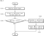
- FIGS. 4 and 5 are flowcharts illustrating a method for detecting a road surface condition according to an embodiment of the present invention.
- the road surface condition detection apparatus measures a sound signal.
- the road surface condition detection apparatus primarily determines a road surface condition. That is, at the step S20, the road surface condition detection apparatus distinguishes the sound signal measured at the step S10 as a normal state or an abnormal state. In this case, the road surface condition detection apparatus may determine a normal or abnormal state through a generative model and learn the result.
- the road surface condition detection apparatus may secondarily determine the road surface condition at step S40.
- the road surface condition detection apparatus determines the road surface condition including at least one of wet, icy, slush, and snowy conditions.
- the road surface condition detection apparatus may filter a background value and noise from the sound signal and then determine the road surface condition based on a frequency range configured for each road surface condition.
- the road surface condition detection apparatus may determine the road surface condition through a discriminative model and learn the determination result.
- the road surface condition detection apparatus may transmit the determined road surface condition to the management server.
- the management server receives a sound signal from the road surface condition detection apparatus.
- the management server primarily determines a road surface condition. That is, at the step S120, the management server distinguishes the sound signal measured at the step S 110 as a normal state or an abnormal state. In this case, the management server may determine a normal or abnormal state through a generative model and learn the result.
- the management server may secondarily determine the road surface condition at step S140.
- the management server determines the road surface condition including at least one of wet, icy, slush, and snowy conditions.
- the management server may filter a background value and noise from the sound signal and then determine the road surface condition based on a frequency range configured for each road surface condition.
- the management server may determine the road surface condition through a discriminative model and learn the determination result.
- the management server may output the determined road surface condition through an electronic road sign (VMS, variable message signs) or operate a snow removal device installed at a corresponding location relying on the determined road surface condition.
- VMS electronic road sign
- the management server may operate in conjunction with a control system for managing and monitoring a road state or be installed in the control system, and may automatically expose an abnormal road condition and location on a screen.
- the control system may output a warning message through the electronic road sign, spray salt water or calcium chloride through a snow removal device installed on the road, or dispatches a tow vehicle in case of an accident.
Landscapes
- General Physics & Mathematics (AREA)
- Physics & Mathematics (AREA)
- Engineering & Computer Science (AREA)
- Atmospheric Sciences (AREA)
- Life Sciences & Earth Sciences (AREA)
- Structural Engineering (AREA)
- Civil Engineering (AREA)
- Architecture (AREA)
- Business, Economics & Management (AREA)
- Analytical Chemistry (AREA)
- Chemical & Material Sciences (AREA)
- Computer Networks & Wireless Communication (AREA)
- Radar, Positioning & Navigation (AREA)
- Remote Sensing (AREA)
- Tourism & Hospitality (AREA)
- Multimedia (AREA)
- Theoretical Computer Science (AREA)
- Strategic Management (AREA)
- Primary Health Care (AREA)
- Marketing (AREA)
- Human Resources & Organizations (AREA)
- General Health & Medical Sciences (AREA)
- Economics (AREA)
- Health & Medical Sciences (AREA)
- General Business, Economics & Management (AREA)
- Traffic Control Systems (AREA)
- Investigating Or Analyzing Materials By The Use Of Ultrasonic Waves (AREA)
- Operations Research (AREA)
Applications Claiming Priority (2)
| Application Number | Priority Date | Filing Date | Title |
|---|---|---|---|
| KR1020200057140A KR102346533B1 (ko) | 2020-05-13 | 2020-05-13 | 노면 상태 탐지 장치 및 시스템, 이를 이용한 노면 상태 탐지 방법 |
| PCT/KR2021/005994 WO2021230670A1 (ko) | 2020-05-13 | 2021-05-13 | 노면 상태 탐지 장치 및 시스템, 이를 이용한 노면 상태 탐지 방법 |
Publications (2)
| Publication Number | Publication Date |
|---|---|
| EP4151801A1 true EP4151801A1 (de) | 2023-03-22 |
| EP4151801A4 EP4151801A4 (de) | 2023-10-18 |
Family
ID=78524580
Family Applications (1)
| Application Number | Title | Priority Date | Filing Date |
|---|---|---|---|
| EP21803739.8A Pending EP4151801A4 (de) | 2020-05-13 | 2021-05-13 | Vorrichtung und system zur erkennung eines strassenoberflächenzustands und verfahren zur erkennung eines strassenoberflächenzustands unter verwendung davon |
Country Status (6)
| Country | Link |
|---|---|
| US (1) | US12300101B2 (de) |
| EP (1) | EP4151801A4 (de) |
| JP (1) | JP7824887B2 (de) |
| KR (2) | KR102346533B1 (de) |
| CN (1) | CN115605648B (de) |
| WO (1) | WO2021230670A1 (de) |
Families Citing this family (8)
| Publication number | Priority date | Publication date | Assignee | Title |
|---|---|---|---|---|
| KR102346533B1 (ko) * | 2020-05-13 | 2021-12-31 | 에스케이플래닛 주식회사 | 노면 상태 탐지 장치 및 시스템, 이를 이용한 노면 상태 탐지 방법 |
| KR20220153708A (ko) * | 2021-05-11 | 2022-11-21 | 현대모비스 주식회사 | 제어기를 제어하는 방법 및 이를 위한 차량용 통합제어기 |
| CN114327914B (zh) * | 2022-03-07 | 2022-05-06 | 中国气象局公共气象服务中心(国家预警信息发布中心) | 基于多因子边缘计算的山岳景区登山决策方法及系统 |
| KR102431234B1 (ko) * | 2022-04-18 | 2022-08-11 | 주식회사 아이디케이 | 탄성파를 이용한 블랙 아이스 감지 시스템 |
| EP4283256A1 (de) * | 2022-05-23 | 2023-11-29 | TuSimple, Inc. | Systeme und verfahren zur erkennung des zustands einer strassenoberfläche |
| KR102824338B1 (ko) * | 2023-05-10 | 2025-06-24 | 한국건설기술연구원 | 도로결빙정보 생성 시스템 |
| KR102612006B1 (ko) * | 2023-08-17 | 2023-12-11 | 주식회사 에코이앤씨 | 하이앵글식 노면 감지센서와 디지털 시스템으로 제어하는도로 및 보도 융설 시스템, 그리고 그 공법 |
| KR20250128577A (ko) | 2024-02-21 | 2025-08-28 | 전주대학교 산학협력단 | 노면 모니터링 시스템 |
Family Cites Families (33)
| Publication number | Priority date | Publication date | Assignee | Title |
|---|---|---|---|---|
| JPS5436442B2 (de) * | 1972-09-22 | 1979-11-09 | ||
| JPS62212590A (ja) * | 1986-03-14 | 1987-09-18 | Matsushita Electric Ind Co Ltd | 路面凍結警告装置 |
| JPS63228397A (ja) * | 1987-03-18 | 1988-09-22 | 松下精工株式会社 | 路面凍結警報装置 |
| JPS63268805A (ja) * | 1987-04-28 | 1988-11-07 | 松下精工株式会社 | 路面凍結検知装置 |
| US5347456A (en) * | 1991-05-22 | 1994-09-13 | The Regents Of The University Of California | Intelligent roadway reference system for vehicle lateral guidance and control |
| US5852243A (en) * | 1997-07-21 | 1998-12-22 | J-Squared, Llc | Method and apparatus for detecting a road pavement surface condition |
| JPH11126295A (ja) | 1997-10-23 | 1999-05-11 | Tokimec Inc | 道路情報提示方法およびその装置 |
| JP2000285374A (ja) * | 1999-03-31 | 2000-10-13 | Toshiba Corp | 移動体の異常状況把握装置 |
| KR100378956B1 (ko) * | 2000-01-26 | 2003-04-08 | 이수갑 | 음향을 이용한 교통 감지 장치 |
| JP2002256521A (ja) | 2001-03-02 | 2002-09-11 | Furukawa Electric Co Ltd:The | 路面状況検出方法及び装置 |
| JP3740524B2 (ja) * | 2001-03-08 | 2006-02-01 | 国土交通省国土技術政策総合研究所長 | 走行支援道路システム |
| KR100818398B1 (ko) * | 2001-05-26 | 2008-04-01 | 엘지전자 주식회사 | 노면상태 및 교통상황 정보제공 시스템 및 방법 |
| FR2834180B1 (fr) * | 2001-12-20 | 2004-03-12 | Org Europeene De Rech | Procede de fabrication d'un module multicouches a circuits imprimes a haute densite |
| US7688222B2 (en) * | 2003-09-18 | 2010-03-30 | Spot Devices, Inc. | Methods, systems and devices related to road mounted indicators for providing visual indications to approaching traffic |
| FR2874539B1 (fr) * | 2004-09-01 | 2006-10-13 | Siemens Vdo Automotive Sas | Procede et un dispositif de filtrage des informations emises par un capteur de pression monte sur une roue d'un vehicule |
| KR20060021496A (ko) * | 2004-09-03 | 2006-03-08 | (주)아크시스템 | 결로 방지 장치 및 그 방법 |
| JP2006351000A (ja) | 2005-05-13 | 2006-12-28 | Tohoku Regional Bureau Ministry Of Land Infrastructure & Transport | 路面状況判定方法およびその装置 |
| US8325718B2 (en) * | 2006-07-03 | 2012-12-04 | Palo Alto Research Center Incorporated | Derivation of a propagation specification from a predicted utility of information in a network |
| JP5097470B2 (ja) | 2006-11-14 | 2012-12-12 | 名古屋電機工業株式会社 | 路面状況判定方法及びその装置 |
| JP5436442B2 (ja) * | 2008-10-30 | 2014-03-05 | 株式会社ブリヂストン | 路面状態推定方法 |
| US20160221581A1 (en) * | 2015-01-29 | 2016-08-04 | GM Global Technology Operations LLC | System and method for classifying a road surface |
| KR101731050B1 (ko) | 2016-11-09 | 2017-04-28 | 한국건설기술연구원 | 음향센서, 레이더센서 및 영상센서를 결합한 복합센서를 이용한 돌발상황 자동 검지장치 및 그 방법 |
| KR101857663B1 (ko) | 2016-11-15 | 2018-05-14 | 유영훈 | IoT 결합형 열선을 이용한 결로방지 시스템 및 방법 |
| KR102011008B1 (ko) * | 2017-04-25 | 2019-08-16 | 만도헬라일렉트로닉스(주) | 노면 상태 감지 시스템 및 방법 |
| KR101883295B1 (ko) * | 2017-11-14 | 2018-08-30 | 주식회사 한울씨앤비 | 노면 상태 감지기 및 이를 이용한 도로포장 유지관리 시스템 |
| KR20190107394A (ko) * | 2018-03-12 | 2019-09-20 | (주)다모아패키지 | 방향성 보냉제, 이를 포함하는 보냉팩 및 그 제조방법 |
| KR20190140272A (ko) * | 2018-06-11 | 2019-12-19 | 이상현 | 블랙 아이스 감지 장치 및 방법 |
| KR101967585B1 (ko) * | 2018-09-07 | 2019-04-15 | 주식회사 시로코 | 결빙 감지용 표면멀티센서 및 이를 이용하는 결빙 감지 방법 |
| KR101962961B1 (ko) * | 2018-09-07 | 2019-03-28 | 주식회사 시로코 | 표면멀티센서를 이용하여 도로의 상황을 판단하는 시스템 |
| CN109859471A (zh) * | 2019-02-27 | 2019-06-07 | 长安大学 | 一种高速公路隧道进出口过渡段路面行车安全综合预警与反馈系统及方法 |
| US11620907B2 (en) * | 2019-04-29 | 2023-04-04 | Qualcomm Incorporated | Method and apparatus for vehicle maneuver planning and messaging |
| CN110085045A (zh) * | 2019-05-05 | 2019-08-02 | 方星星 | 道路及行车实时安全监测、导航系统和安全监测方法 |
| KR102346533B1 (ko) * | 2020-05-13 | 2021-12-31 | 에스케이플래닛 주식회사 | 노면 상태 탐지 장치 및 시스템, 이를 이용한 노면 상태 탐지 방법 |
-
2020
- 2020-05-13 KR KR1020200057140A patent/KR102346533B1/ko active Active
-
2021
- 2021-05-13 US US17/920,728 patent/US12300101B2/en active Active
- 2021-05-13 EP EP21803739.8A patent/EP4151801A4/de active Pending
- 2021-05-13 CN CN202180034774.4A patent/CN115605648B/zh active Active
- 2021-05-13 JP JP2022566408A patent/JP7824887B2/ja active Active
- 2021-05-13 WO PCT/KR2021/005994 patent/WO2021230670A1/ko not_active Ceased
- 2021-11-25 KR KR1020210164693A patent/KR102609459B1/ko active Active
Also Published As
| Publication number | Publication date |
|---|---|
| JP7824887B2 (ja) | 2026-03-05 |
| US20230169856A1 (en) | 2023-06-01 |
| KR20210148050A (ko) | 2021-12-07 |
| JP2023525681A (ja) | 2023-06-19 |
| KR20210138977A (ko) | 2021-11-22 |
| US12300101B2 (en) | 2025-05-13 |
| CN115605648A (zh) | 2023-01-13 |
| WO2021230670A1 (ko) | 2021-11-18 |
| CN115605648B (zh) | 2025-08-26 |
| EP4151801A4 (de) | 2023-10-18 |
| KR102609459B1 (ko) | 2023-12-01 |
| KR102346533B1 (ko) | 2021-12-31 |
Similar Documents
| Publication | Publication Date | Title |
|---|---|---|
| US12300101B2 (en) | Apparatus and system for detecting road surface condition and method for detecting road surface condition by using same | |
| KR101331054B1 (ko) | 도로노면정보 및 통계적 교통상황을 고려한 안전속도 산정방법 및 그 장치 | |
| KR102312714B1 (ko) | 도로 상태를 판단하기 위한 멀티센서 및 도로 상태 판단 방법이 적용된 스마트 도로상황 알림 시스템 | |
| CN102963361A (zh) | 操作车辆安全系统的方法 | |
| CN202134106U (zh) | 一种智能车载路况采集仪 | |
| CN206938738U (zh) | 一种汽车刹车片检测装置 | |
| CN108564803B (zh) | 一种车辆超速提醒方法及系统 | |
| KR102297801B1 (ko) | 사업용 차량을 이용하여 도로 위험정보를 탐지하는 방법 및 장치 | |
| US20230245509A1 (en) | Safety system and method for motor vehicles | |
| Hou et al. | VehSense: Slippery road detection using smartphones | |
| KR101750939B1 (ko) | 주행차량을 이용한 기상상태-기반 노면상태 예측 시스템 및 예측 방법 | |
| CN106772689A (zh) | 一种高速公路气象监测系统 | |
| KR102413836B1 (ko) | 화물차용 도로정보 및 교통안전정보 제공 시스템 및 방법 | |
| KR102312382B1 (ko) | 중력가속도 센서와 휠스피드 센서를 이용한 노면 미끄럼정보 제공 시스템 및 그 방법 | |
| EP4253996A1 (de) | System zur erkennung von schwarzem eis auf einer strasse unter verwendung eines strahlformungsarrayradars | |
| KR102882840B1 (ko) | 도로 결빙에 따른 블랙아이스 정보 제공 시스템 및 그 방법 | |
| JP2002162478A (ja) | 道路気象検出方法及び検出システム | |
| KR102501312B1 (ko) | 가속도센서를 이용한 노면상태 연속 측정 시스템 및 그 방법 | |
| CN204154309U (zh) | 图像与激光复合式遥感路面监测装置 | |
| KR20220150066A (ko) | 블랙 아이스 검출방법 및 이를 이용한 블랙 아이스 검출 시스템 | |
| CN206805786U (zh) | 一种恶劣天气条件下的可变限速控制系统 | |
| JP2004299554A (ja) | 車両用タイヤ空気圧判定装置 | |
| CN118247946B (zh) | 一种冰雪条件下基于v2x的交通安全预警系统与方法 | |
| CN110686799A (zh) | 一种桥面温度远程智能监控终端平台系统 | |
| KR20250164398A (ko) | 가변형 속도제한 정보 제공시스템 |
Legal Events
| Date | Code | Title | Description |
|---|---|---|---|
| STAA | Information on the status of an ep patent application or granted ep patent |
Free format text: STATUS: THE INTERNATIONAL PUBLICATION HAS BEEN MADE |
|
| PUAI | Public reference made under article 153(3) epc to a published international application that has entered the european phase |
Free format text: ORIGINAL CODE: 0009012 |
|
| STAA | Information on the status of an ep patent application or granted ep patent |
Free format text: STATUS: REQUEST FOR EXAMINATION WAS MADE |
|
| 17P | Request for examination filed |
Effective date: 20221108 |
|
| AK | Designated contracting states |
Kind code of ref document: A1 Designated state(s): AL AT BE BG CH CY CZ DE DK EE ES FI FR GB GR HR HU IE IS IT LI LT LU LV MC MK MT NL NO PL PT RO RS SE SI SK SM TR |
|
| P01 | Opt-out of the competence of the unified patent court (upc) registered |
Effective date: 20230606 |
|
| DAV | Request for validation of the european patent (deleted) | ||
| DAX | Request for extension of the european patent (deleted) | ||
| REG | Reference to a national code |
Ref country code: DE Ref legal event code: R079 Free format text: PREVIOUS MAIN CLASS: E01F0009400000 Ipc: E01C0023010000 |
|
| A4 | Supplementary search report drawn up and despatched |
Effective date: 20230914 |
|
| RIC1 | Information provided on ipc code assigned before grant |
Ipc: G06Q 50/30 20120101ALI20230908BHEP Ipc: G01S 1/74 20060101ALI20230908BHEP Ipc: G08G 1/0967 20060101ALI20230908BHEP Ipc: E01F 9/40 20160101ALI20230908BHEP Ipc: E01C 23/01 20060101AFI20230908BHEP |
|
| STAA | Information on the status of an ep patent application or granted ep patent |
Free format text: STATUS: EXAMINATION IS IN PROGRESS |
|
| 17Q | First examination report despatched |
Effective date: 20250731 |