EP4151328B1 - Nahtformungsvorrichtung für ellbogenrohr - Google Patents
Nahtformungsvorrichtung für ellbogenrohr Download PDFInfo
- Publication number
- EP4151328B1 EP4151328B1 EP21849971.3A EP21849971A EP4151328B1 EP 4151328 B1 EP4151328 B1 EP 4151328B1 EP 21849971 A EP21849971 A EP 21849971A EP 4151328 B1 EP4151328 B1 EP 4151328B1
- Authority
- EP
- European Patent Office
- Prior art keywords
- forming
- seam
- elevating
- elbow duct
- pair
- Prior art date
- Legal status (The legal status is an assumption and is not a legal conclusion. Google has not performed a legal analysis and makes no representation as to the accuracy of the status listed.)
- Active
Links
Images


Classifications
-
- B—PERFORMING OPERATIONS; TRANSPORTING
- B21—MECHANICAL METAL-WORKING WITHOUT ESSENTIALLY REMOVING MATERIAL; PUNCHING METAL
- B21C—MANUFACTURE OF METAL SHEETS, WIRE, RODS, TUBES, PROFILES OR LIKE SEMI-MANUFACTURED PRODUCTS OTHERWISE THAN BY ROLLING; AUXILIARY OPERATIONS USED IN CONNECTION WITH METAL-WORKING WITHOUT ESSENTIALLY REMOVING MATERIAL
- B21C37/00—Manufacture of metal sheets, rods, wire, tubes, profiles or like semi-manufactured products, not otherwise provided for; Manufacture of tubes of special shape
- B21C37/06—Manufacture of metal sheets, rods, wire, tubes, profiles or like semi-manufactured products, not otherwise provided for; Manufacture of tubes of special shape of tubes or metal hoses; Combined procedures for making tubes, e.g. for making multi-wall tubes
- B21C37/10—Making tubes with seams being neither welded nor soldered, e.g. riveted seams
- B21C37/101—Making of the seams
-
- B—PERFORMING OPERATIONS; TRANSPORTING
- B21—MECHANICAL METAL-WORKING WITHOUT ESSENTIALLY REMOVING MATERIAL; PUNCHING METAL
- B21C—MANUFACTURE OF METAL SHEETS, WIRE, RODS, TUBES, PROFILES OR LIKE SEMI-MANUFACTURED PRODUCTS OTHERWISE THAN BY ROLLING; AUXILIARY OPERATIONS USED IN CONNECTION WITH METAL-WORKING WITHOUT ESSENTIALLY REMOVING MATERIAL
- B21C37/00—Manufacture of metal sheets, rods, wire, tubes, profiles or like semi-manufactured products, not otherwise provided for; Manufacture of tubes of special shape
- B21C37/06—Manufacture of metal sheets, rods, wire, tubes, profiles or like semi-manufactured products, not otherwise provided for; Manufacture of tubes of special shape of tubes or metal hoses; Combined procedures for making tubes, e.g. for making multi-wall tubes
- B21C37/10—Making tubes with seams being neither welded nor soldered, e.g. riveted seams
- B21C37/104—Making tubes with seams being neither welded nor soldered, e.g. riveted seams the tubes having a special shape, e.g. polygonal tubes
-
- B—PERFORMING OPERATIONS; TRANSPORTING
- B21—MECHANICAL METAL-WORKING WITHOUT ESSENTIALLY REMOVING MATERIAL; PUNCHING METAL
- B21D—WORKING OR PROCESSING OF SHEET METAL OR METAL TUBES, RODS OR PROFILES WITHOUT ESSENTIALLY REMOVING MATERIAL; PUNCHING METAL
- B21D19/00—Flanging or other edge treatment, e.g. of tubes
- B21D19/02—Flanging or other edge treatment, e.g. of tubes by continuously-acting tools moving along the edge
- B21D19/04—Flanging or other edge treatment, e.g. of tubes by continuously-acting tools moving along the edge shaped as rollers
- B21D19/046—Flanging or other edge treatment, e.g. of tubes by continuously-acting tools moving along the edge shaped as rollers for flanging edges of tubular products
-
- B—PERFORMING OPERATIONS; TRANSPORTING
- B21—MECHANICAL METAL-WORKING WITHOUT ESSENTIALLY REMOVING MATERIAL; PUNCHING METAL
- B21D—WORKING OR PROCESSING OF SHEET METAL OR METAL TUBES, RODS OR PROFILES WITHOUT ESSENTIALLY REMOVING MATERIAL; PUNCHING METAL
- B21D39/00—Application of procedures in order to connect objects or parts, e.g. coating with sheet metal otherwise than by plating; Tube expanders
- B21D39/04—Application of procedures in order to connect objects or parts, e.g. coating with sheet metal otherwise than by plating; Tube expanders of tubes with tubes; of tubes with rods
-
- Y—GENERAL TAGGING OF NEW TECHNOLOGICAL DEVELOPMENTS; GENERAL TAGGING OF CROSS-SECTIONAL TECHNOLOGIES SPANNING OVER SEVERAL SECTIONS OF THE IPC; TECHNICAL SUBJECTS COVERED BY FORMER USPC CROSS-REFERENCE ART COLLECTIONS [XRACs] AND DIGESTS
- Y02—TECHNOLOGIES OR APPLICATIONS FOR MITIGATION OR ADAPTATION AGAINST CLIMATE CHANGE
- Y02E—REDUCTION OF GREENHOUSE GAS [GHG] EMISSIONS, RELATED TO ENERGY GENERATION, TRANSMISSION OR DISTRIBUTION
- Y02E30/00—Energy generation of nuclear origin
- Y02E30/30—Nuclear fission reactors
Definitions
- the present disclosure relates to a device for forming seam of elbow duct, and more particularly, to a device for forming seam of elbow duct, that is capable of easily forming a lockseam on a connecting portion of a plurality of unit members constituting the elbow duct.
- Korean Laid-open Patent No. 10-2003-0087619 disclosed a fold seam connecting part consisting of a first fold having the shape of a flange on a connecting portion of an elbow type duct consisting of a plurality of unit members, and a second fold surrounding an outer side of the dual fold.
- US 2017/320119 A1 discloses an elbow-shaped duct manufacturing device comprising an angled base and pressing rollers.
- a purpose of the present disclosure is to resolve such problems of prior art, that is to provide a device for forming seam of elbow according to claim 1, that is capable of easily forming a lockseam on a connecting portion of a plurality of unit members constituting the elbow duct.
- Another purpose of the present disclosure is to provide a device for forming seam of elbow duct, that is capable of easily forming a seam on a connecting portion of unit members having different angles of a lower supporting surface.
- another purpose of the present disclosure is to provide a device for forming seam of elbow duct, that is capable of forming a seam in a state in which an inner circumferential surface of a connecting portion of one pair of unit members is closely supported, thereby preventing the shape of the connecting portion from being deformed in the forming process of the seam.
- a device for forming seam of elbow duct that molds a lockseam by bending a flange of one pair of adjacent unit members among a plurality of unit members constituting the elbow duct, including a base that supports a lower portion of the one pair of unit members; an elevating part that moves the base up and down; an angle adjustment part that adjusts a supporting angle of the base; a fixing chuck that supports an inner circumferential surface of a connecting portion of the one pair of unit members; a rotating part that rotates the fixing chuck; and a forming part that bends the flange of the one pair of unit members in a state where the flange is in contact to each other, to form the seam.
- the elevating part includes an elevating table that supports a lower portion of the base and an elevation driving part that moves the elevating table up and down.
- the elevation driving part includes a plurality of elevating shafts that are disposed to be parallel with a movement direction of the elevating table and that are fixed to a lower portion of the elevating table; a connecting shaft that is disposed in a direction intersecting the elevating shaft and that connects one pair of adjacent elevating shafts; and a driving motor for elevation that provides a rotation driving force to the connecting shaft, and a rack and a pinion are formed on a connecting portion of the connecting shaft and the elevating shaft, so that an axial direction position of the elevating shaft is adjusted by an axial rotation of the connecting shaft.
- the angle adjustment part includes a rotation axis that rotatably connects the elevating table and the base; and an interval adjustment part that connects the elevating table and one side of the base in a position distanced from the rotation axis, and that adjusts an interval between the elevating table and the base to adjust an angle of the base.
- the fixing chuck includes a chuck main body and a plurality of supporting members each of which is moveably disposed radially on the chuck main body, and on an outer circumferential surface of the supporting member, a supporting surface is formed that supports an inner circumferential surface of the connecting portion of the one pair of unit members.
- the supporting surface is made in a shape corresponding to the inner circumferential surface of the connection portion of the one pair of unit members.
- the supporting surface is assembled to be attachable/detachable on the supporting member.
- the fixing chuck further includes an elevating pin that is elevatably disposed at a center of the plurality of supporting members and that moves the supporting member in an expanding direction according to an elevation position.
- the fixing chuck further includes a spring member that is provided between the supporting member and the chuck main body and that elastically supports the supporting member in a contraction direction.
- a guide groove is provided along a movement direction, and on an upper surface of the chuck main body, a guide projection is formed, to be inserted into the guide groove.
- the forming part includes a moving part that is disposed to be moveable in a direction approaching towards or distancing away from a center of the fixing chuck outside of the connecting portion of the one pair of unit members; a forward and backward driving part that moves the moving part forward and backward; and a forming roller that moves forward and backward together with the moving part on the moving part and that is supported to be axially rotatable.
- the forming part further includes a roller bracket that is disposed to be movable in a direction parallel with a movement direction of the moving part on the moving part in a state of supporting the forming roller; and an elastic member that is interposed between the moving part and the roller bracket and that elastically supports the roller bracket in a forward direction.
- the forming part includes a first forming part, a second forming part and a third forming part, that are disposed in plurality radially around the fixing chuck.
- the forming roller of the first forming part includes a first forming surface that forms a standing seam by bending an end of a first flange in a state where the first flange having '-' shape formed on a lower side edge of an upper unit member is seated on an upper side of a second flange having ' ' shape formed on an upper side edge of a lower unit member.
- the forming roller of the second forming part includes a second forming surface that bends the seam formed by the first forming part and disposed in a horizontal direction to be inclined towards an outer surface of the duct.
- the forming roller of the third forming part includes a third forming surface that places the seam bent by the second forming part closely to the outer surface of the duct, to form a lock seam.
- the device for forming seam of elbow duct further includes a holder that rotatably supports the one pair of unit members.
- the holder is disposed on the moving part of the forming part, and disposed to be able to go forward and backward in a direction towards the fixing chuck on the moving part.
- a roller is disposed on a front end of the holder.
- FIG. 1 is a perspective view of a device for forming seam of elbow duct of the present invention
- FIG. 2 is an excerpt perspective view of an elevating part and an angle adjustment part of a device for forming seam of elbow duct of the present invention
- FIG. 3 is an excerpt perspective view of a fixing chuck and a rotating part of a device for forming seam of elbow duct of the present invention
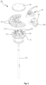
- FIG. 4 is an exploded perspective view of a fixing chuck of a device for forming seam of elbow duct of the present invention
- FIG. 5 is an excerpt perspective view of a forming part and a holder of a device for forming seam of elbow duct of the present invention
- FIG. 6 is an exploded perspective view of a forming part of a device for forming seam of elbow duct of the present invention.
- the device for forming seam of elbow duct of the present invention as illustrated in the aforementioned drawings is capable of forming a first flange F1 and a second flange F2 formed on one pair of adjacent unit members Da and Db among a plurality of unit members constituting an elbow duct, in a lockseam form, to improve sealing power and coupling power, and largely includes a device main body 10, a base 20, an elevating part 30, an angle adjustment part 40, a fixing chuck 50, a rotating part 60, a forming part and a holder 80.
- the device main body 10 may include the elevating part 30 supporting a lower portion of the base 20, a first table 11 supporting the fixing chuck 50 and the rotating part 60, and a second table 12 supporting the forming part, and on a plane surface of the second table 12, an opening may be formed, and the first table 11 may be connected with the second table 12 at a lower side of the opening.
- the base 20 is for guiding an assembly position of the one par of unit members Da and Db so that a connecting portion of the one pair of unit members Da and Db can be positioned between the fixing chuck 50 and the forming part, and the base 20 may include a ring-type support 21 that can support a lower end of the lower unit member Da, of the one pair of unit members Da and Db. It is preferable that the ring-type support 21 is provided in a plurality of various sizes, and be composed to be selectively applied according to the standard of the duct that is the subject of the work.
- the elevating part 30 is for moving the base 20 up and down on the first table 11, and includes an elevating table 31 for supporting a lower portion of the base 20, and an elevation driving part 42 for moving the elevating table 31 up and down.
- the elevation driving part 42 includes a plurality of elevating shafts 32 that are disposed to be moveable along a movement direction of the elevating table 31 on the first table 11 and that has a top end fixed below the elevating table 31, a plurality of connecting shafts 33 that are disposed in a direction intersecting the elevating shaft 32 and that connects each of the one pair of adjacent elevating shafts 32, and a driving motor for elevation 34 that provides a rotation driving force to one of the plurality of connecting shafts 33.
- a rack 32a and a pinion 33a are each formed, and thus by an axial rotation of the connecting shaft 33, an axial direction position of the elevating shaft 32 may be adjusted.
- the elevating part 30 may further include a housing 35 that surrounds the connecting portion of the connecting shaft 33 and the elevating shaft 32 and that supports the axial position of each of the connecting shaft 33 and the elevating shaft 32.
- the base 20 may support the lower unit member Da, of the one pair of unit members Da and Db stacked up and down, to guide an assembly position of the one pair of unit members Da and Db, and after the lower unit member Da is supported in a rotatable state by the holder 80, the base 20 is descended by the elevating part 30. Accordingly, the base 20 and the lower unit member Da may be prevented from interfering with each other in a process where the lower unit member Da rotates in order to mold a lockseam. That is, it is preferable that a position the base 20 is descended by the elevating part 30 is set as a position that can sufficiently deviate from a rotation region of the lower unit member Da.
- the elbow duct is composed of a plurality of unit members D1, D2, D3, D4 and D5, and the plurality of unit members D1, D2, D3, D4 and D5, may be divided into end unit members D1 and D5 positioned at both ends, and intermediate unit members D2, D3 and D4 positioned between the both ends.
- a cut surface corresponding to a connecting portion of the plurality of unit members D1, D2, D3, D4 and D5 is designed to have an angle between them that is not perpendicular to a central axial line of each unit member, and an outer cut surface of the end unit member D1 and D5 is designed to be perpendicular to the central axial line of each unit member.
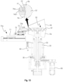
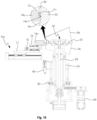
- the angle adjustment part 40 is composed to be able to adjust the base 20 that guides the assembly position of the lower unit member Da to a first supporting angle a1 when the intermediate unit member D2, D3 and D4 is disposed as the lower unit member Da, and to adjust the base 20 to a second supporting angle a2 that is different from the first supporting angle when the end unit member is disposed as the lower unit member Da. (refer to FIG. 16 )
- Such an angle adjustment part 40 may include a rotation axis 41 that rotatably connects the elevating table 31 and the base 20, and an interval adjustment part that connects the elevating table 31 and one side of the base 20 at a position distanced from the rotation axis 41, and that adjusts an interval between the base 20 and the elevating table 31 to adjust the angle of the base 20.
- the interval adjustment part may include a driving part 42 that connects the base 20 and one side of the elevating table 31 and that extends and contracts so that the connection length can be adjusted; a first stopper 43 that is disposed at one side of the elevating table 31 with respect to the rotation axis 41 and that comes in contact with the base 20 when the driving part 42 has extended, to guide the first supporting angle of the base 20; and a second stopper 44 that is disposed at the other side of the elevating table 31 with respect to the rotation axis 41 and that comes in contact with the base 20 when the driving part 42 has contracted, to guide the second supporting angle of the base 20.
- a driving part 42 that connects the base 20 and one side of the elevating table 31 and that extends and contracts so that the connection length can be adjusted
- a first stopper 43 that is disposed at one side of the elevating table 31 with respect to the rotation axis 41 and that comes in contact with the base 20 when the driving part 42 has extended, to guide the first supporting angle of the base 20
- first supporting angle and the second supporting angle may be changed according to the standard of the duct
- first stopper 43 and the second stopper 44 are composed to be able to control the supporting angle of the base 20 according to the standard of the duct.
- first stopper 43 and the second stopper 44 may be composed to be screwed onto the elevating table 31 to adjust the length protruding towards the base 20.
- the fixing chuck 50 is for supporting the inner circumferential surface of the connecting portion of the one pair of unit members Da and Db
- the fixing chuck 50 includes a chuck main body 51 having a moving hole 51a in its center in a vertical direction, a plurality of supporting members 52 each of which is moveably disposed radially around the moving hole 51a on the chuck main body 51 and has, on its outer circumferential surface, a supporting surface 52b that can support the inner circumferential surface of the connecting portion of the one pair of unit members Da and Db, an elevating pin 53 that is disposed such that it is elevatable at a position corresponding to the moving hole 51a and that can be inserted inside the moving hole 51a to move the supporting member 52 to an expandable direction, a cover 54 that is disposed with a distance at an upper side of the chuck main body 51 and that covers an upper side of the plurality of supporting members 52, and a spacer 55 that maintains the interval between the cover 54 and the chuck main body 51.
- a guide groove 52a is provided along the movement direction, and on an upper surface of the chuck main body 51, a guide projection 51b is formed that may be inserted inside the guide groove 52a, and between the guide projection 51b and the guide groove 52a, a spring member 57 may be provided to elastically support the supporting member 52 in a contraction direction.
- the supporting surface 52b may support the inner circumferential surface of the connecting portion of the one pair of unit members Da and Db and the spring member 57 may be compressed at the same time, and when the elevating pin 53 descends, by the elastic restoring force of the spring member 57, the supporting member 52 may move in a contraction direction, so that the supporting surface 52b is distanced from the inner circumferential surface of the connecting portion of the one pair of unit members Da and Db.
- the fixed chuck 50 further includes a slip pad 56 interposed between the chuck body 51 and the cover 54 on the upper and lower surfaces of the support member 52, respectively, and by such a slip pad 56, the supporting member 52 is prevented from directly contacting the chuck main body 51 and the cover 54 and the moving friction is minimized, thereby allowing each of the numerous supporting members 52 to smoothly move radially according to the elevation position of the elevating pin 53.
- an upper end edge of the elevating pin 53 is made in a slope surface, and the portion that contacts the upper end of the elevating pin 53 of the supporting member 52 is made in a slope surface having an inclination corresponding to the slope surface of the elevating pin 53.
- the supporting member 52 is formed in a fan shape, and multiple supporting members 52 are disposed around the moving hole 51a of the chuck main body 51 to form a circular disc as a whole.
- a central axis of the connecting portion of the one pair of unit members Da and Db constituting the elbow duct forms a predetermined angle between them, in 3 o'clock direction and 9 o'clock direction with respect to the center of the connecting portion, the inner circumferential surface of the one pair of unit members Da and Db are parallel to each other, and in 6 o'clock direction, the angle between the inner circumferential surface of the one pair of unit members Da and Db consists of a right angle that is greater than 180 degrees, and in 12 o'clock direction, the angle between the inner circumferential surface of the one pair of unit members Da and Db consists of an obtuse angle that is smaller than 180 degrees.
- the supporting surface 52b is formed in a shape corresponding to the shape of the inner circumferential surface of the connecting portion of the one pair of unit members Da and Db, and may be assembled to be attachable/detachable to/from the supporting member 52. Accordingly, since it is possible to provide a supporting surface 52b that corresponds to a duct of various standards, and select a supporting surface 52b that corresponds to the desired standard duct and apply it to the supporting member 52, it is possible to manufacture an elbow duct of various standards using one device.
- the entire outer edge shape of the plurality of supporting members 52 is formed to correspond to the cross-sectional shape of the connecting portion of the one pair of unit members Da and Db, so that when the one pair of unit members Da and Db are gripped using the fixing chuck 50, the cross-sectional shape of the connecting portion of the one pair of unit members Da and Db can be prevented from being deformed.
- the shape of the inner circumferential surface of the connecting portion of the one pair of adjacent unit members Da and Db, of the plurality of unit members constituting the elbow duct is composed to have, based on a central point of the connecting portion, a between angle of 180 degrees in 3 o'clock direction and 9 o'clock direction, and a between angle of a right angle (angle greater than 180 degrees) in 12 o'clock direction, and a between angle of an obtuse angle (angle smaller than 180 degrees) in 6 o'clock direction, and such a shape to gradually be deformed in an intermediate region.
- the shape of the supporting surface 52a disposed at an outer side of the plurality of supporting members 52 to correspond to the shape of the inner circumferential surface of the connecting portion of the one pair of unit members Da and Db, it is possible to prevent the shape of the inner circumferential surface of the connecting portion of the one pair of unit members Da and Db from being deformed in a process of bending a first flange F1 and A second flange F2 to mold a seam.
- a driving part 42 may be disposed that can provide the driving force for elevation of the elevating pin 53, and the driving part 42 may be made in a form that can be extended and contracted, such as an air cylinder.
- the rotating part 60 is for rotating the fixing chuck 50, and is provided with a hollow part that can accommodate the elevating pin 53 therein in a moveable state along a longitudinal direction, and includes a shaft 61 that may be fixed at a lower portion of the fixing chuck 50, and a rotation driving part 62 for axially rotating the shaft 61.
- the rotation driving part 62 may consist of a driving motor and a power transmission part, and the power transmission part may consist of a belt and a pulley.
- the shaft 61 may be disposed on coaxially with the elevating pin 53, and for this purpose, the shaft 61 may be made in the form of a hollow pipe capable of accommodating the elevating pin in an internal space.
- the forming part is for bending and forming in the form of a lockseam in a state where the first flange F1 of the lower unit member Da and the second flange F2 of the upper unit member Db are in contact to each other.
- the forming part includes a moving part 71 disposed to be moveable in a direction towards a center of the fixing chuck 50 on a plane, a forward and backward driving part 72 for moving the moving part 71 forward and backward, a roller bracket 73 that is supported to be moveable in a direction parallel to the movement direction of the moving part 71 on the moving part 71, a forming roller that is axially rotatably disposed at a front end of the roller bracket 73, and an elastic member 75 that is interposed between the moving part 71 and the roller bracket 73 and that elastically supports the roller bracket 73 in a forward direction.
- the forward and backward driving part 72 may include a driving motor, a ball screw that may be rotated by the driving motor, and a ball nut that may be fixed to the moving part 71 and that may be engaged with the ball screw, and the ball screw may be connected with the driving motor through the belt and pulley, to receive the driving force. Further, the moving part 71 and the roller bracket 73 may each be guided in a linear reciprocating motion by an LM guide and the like.
- the forming part is provided in plurality, and the plurality of forming parts are disposed radially around the fixing chuck 50, and are composed to bend the first flange F1 of the lower unit member Da and the second flange F2 of the upper unit member Db stepwise, to mold in the form of a lockseam.
- the forming part may consist of a first forming part 70a having a first forming roller 74a for bending an end of a first flange F1 to form a standing seam, in a state where a second flange F2 of '-' shape is seated on an upper side of a first flange F1 of ' ' shape, a second forming part 70b having a second forming roller 74b for bending the seam, that is primarily formed by the first forming roller 74a and disposed in a horizontal direction, to be inclined towards an outer surface of the duct, and a third forming part 70c having a third forming roller 74c for placing the seam that is upwardly bent by the second forming roller 74b to closely contact the outer surface of the duct, to form a lockseam.
- the first forming roller 74a is made to have a form in which a first forming surface 74a1 is recessed in a horizontal direction at a center of an outer circumferential surface, and in a process where the first forming roller 74a goes forward towards the fixing chuck 50, an end of the first flange F1 is bent in the form of surrounding the second flange F2, thereby forming the standing seam.
- the second forming roller 74b is made in a recessed form such that a second forming surface 74b1 is disposed in an upper direction inclined by about 45 degrees at a center of an outer circumferential surface, and in a process where the second forming roller 74b goes forward towards the fixing chuck 50, the standing seam may be bent in an upper direction along the second forming surface 74b1.
- the third forming roller 74c has a third forming surface 74c1 on an outer circumferential surface, and in a process in which the third forming roller 74c goes forward towards the fixing chuck 50, the upwardly bent seam is placed in close contact to the outer surface of the upper unit member Db by the third forming surface 74c1 of the second forming roller 74b, thereby completing the lockseam.
- the connecting portion of the lower unit member Da and the upper unit member Db has an elliptical cross-sectional shape
- the forming roller is elastically supported by an elastic member 75, and molds the seam in a state of being in close contact along the outer circumferential surface of the connecting portion while going forward and backward within an elastic range of the elastic member 75, thus it is possible to prevent distortion of the connecting portion or deterioration of the forming quality of the seam.
- the standing seam has a large frictional resistance during forming, and thus an eccentric load is applied to the rotating unit member, which causes the problem where the first flange F1 and the second flange F2 of the one pair of unit members Da and Db being separated from the first forming surface 74a1 of the first forming roller 74a.
- the first forming part 70a is provided in plurality, and are disposed in a relatively symmetrical form at both sides of the one pair of unit members Da and Db.
- the holder 80 can support the first flange F1 of the lower unit member Da on the second table 12 of the device main body 10, and the holder 80 may be disposed on the moving part of the first forming part 70a, and since the holder 80 is disposed such that it can go forward and backward in a direction facing towards the fixing chuck 50 on the moving part 71, the position of the holder 80 can be adjusted according to the standard of the duct that is the subject of work, and the state of supporting the first flange F1 can be maintained in the process of forwarding and backwarding the forming roller. Meanwhile, at a front end of the holder 80, a roller 80 may be disposed, that freely rotates while supporting the unit member in order to minimize contact friction with the duct.
- the holder 80 is provided at both sides of the plurality of first forming parts 70a, respectively, but besides this, it is possible to implement various types of modifications that can stably support the rotation of the unit member on the second table 11. For example, even when manufacturing a large elbow duct, it will be preferable to compose the number of the holder 80 to increase or decrease according to the diameter of the duct that is the subject of work so as to stably support the rotation of the unit member.
- FIG. 7 is a plane view of a device for forming seam of elbow duct of the present disclosure
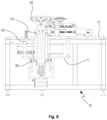
- FIG. 8 is a side cross-section view of a device for forming seam of elbow duct of the present disclosure
- FIG. 9 is a front cross-section view of a device for forming seam of elbow duct of the present disclosure.
- the base 20 may elevate in a vertical direction on the first table 11 of the device main body 10 by the elevating part 30, and by the angle adjustment part 40 disposed between the base 20 and the elevating part 30, a supporting angle of the base 20 that supports a lower portion of the lower unit member Da may be adjusted.
- the fixing chuck 50 penetrates through a center of the base 20 and is disposed in a vertical direction, and is supported in an axially rotatable state on the second table, and an upper end of the fixing chuck 50 selectively supports the inner circumferential surface of the connecting portion of the one pair of unit members Da and Db at an upper side of the base 20, thereby fixing or releasing the fixation of the one pair of unit members Da and Db, and a lower end of the fixing chuck may be connected to the rotating part 60 to receive the driving force for an axial rotation.
- the first forming part 70a, the second forming part 70b and the third forming part 70c constituting the forming part are radially disposed around the fixing chuck 50 on the second table 12 of the device main body 10, and the first forming part 70a is provided in plurality, and are disposed at both sides of the fixing chuck 50 such that they are distanced from each other having the second forming part 70b and the third forming part 70c therebetween.
- the holder 80 is disposed at both sides of the first forming part 70a provided in plurality, and when necessary, the holder 80 can go forward and support the one pair of unit members Da and Db in a rotatable state.
- the first flange F1 is provided in ' ' shape, but when the first flange F1 and the second flange F2 of the one pair of unit members Da and Db are each provided in a state where they are extended in a horizontal direction, the forming part may be further provided with a forming part that can mold the first flange F1 of the lower unit member Da in ' ' shape prior to the first forming part 70a.
- FIG. 10 is a view showing a state in which one pair of unit members are supplied in a device for forming seam of elbow duct of the present disclosure
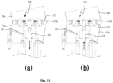
- FIG. 11 is a function view of a fixing chuck of a device for forming seam of elbow duct of the present disclosure
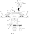
- FIG. 12 is a function view of a holder and an elevating part of a device for forming seam of elbow duct of the present disclosure
- FIGs. 13 to 15 are function views showing a forming process of a lockseam by a forming part of a device for forming seam of elbow duct of the present disclosure
- FIG. 16 is a view showing a process of manufacturing an elbow-type duct through a device for forming seam of elbow duct of the present disclosure.
- the lower unit member Da of the one pair of unit members Da and Db that are subject of connection, is seated on the base 20, and then, the upper unit member Db is positioned at an upper side of the lower unit member Da.
- the elevating position and supporting angle of the base 20 may each be controlled by the elevating part 30 and the angle adjustment part 40, and accordingly, the connecting portion of the one pair of unit members Da and Db being seated on the base 20 may be positioned in an area between the fixing chuck 50 and the first forming part 70a to the third forming part 70c.
- the fixing chuck 50 comes to be positioned at an inner side of the connecting portion of the one pair of unit members Da and Db as illustrated in FIG. 11 , and in a state where the elevating pin 53 is descended as in (a) of FIG. 11 , the plurality of supporting members 52 provided between the cover 54 and the chuck main body 51 of the fixing chuck 50 comes to a contracted state, and thus the supporting surface 52b provided on the outer circumferential surface of the supporting member 52 comes to a distanced state from the inner circumferential surface of the one pair of unit members Da and Db.
- each of the plurality of supporting members 52 comes to move away from a center of the fixing chuck 50, and in this process, the supporting surface 52b provided on the outer circumferential surface of the supporting member 52 may support the inner circumferential surface of the connecting portion of the one pair of unit members Da and Db.
- the holder 80 disposed at both sides of the plurality of first forming parts 70a are forwarded to support the lower portion of the flange F1 and F2 of the one pair of unit members Da and Db in a rotatable state as illustrated in FIG. 12 , and then the base 20 is descended through the elevating part 30, thereby preventing the base 20 from being interfered when the lower unit member Da rotates.
- FIGs. 13 to 15 illustrate the stepwise forming process of a lockseam.
- the fixing chuck 50 when the fixing chuck 50 is axially rotated using the rotating part 60, the one pair of unit members Da and Db supported to the fixing chuck 50 rotates together with the fixing chuck 50.
- the first forming roller 74a of the forming part is forwarded in such a state, by the first forming surface 74a1 of the first forming roller 74a, the first flange F1 and the second flange F2 of the one pair of unit members Da and Db engage each other and are coupled.
- the inner circumferential surface of the one pair of unit members Da and Db is supported by the fixing chuck 50, and thus a smooth forming of the flange F1 and F2 is possible, and the connecting portion of the one pair of unit members Da and Db can be prevented from being damaged by the forming pressure.
- FIG. 16 shows a process of manufacturing an elbow duct by connecting the plurality of unit members D1, D2, D3, D4 and D5.
- the elbow duct consists of five unit members, but there is no limitation thereto.
- the fourth unit member D4 and the third unit member D3 are coupled, and the fourth unit member D4 seated on the base 20 is separated, and after the fifth unit member D5 is positioned as in (d) of FIG. 16 , the fifth unit member D5 and the fourth unit member D4 are coupled, thereby completing the elbow duct composed of the plurality of unit members D1, D2, D3, D4 and D5.
- a surface of the plurality of unit members D1, D2, D3, D4 and D5 constituting the elbow duct, that is connected to an adjacent unit member comes to have a predetermined inclination with respect to the central axis, and an outer surface of the end unit members that are positioned at both ends of the elbow duct, that is, the outer surface of the first unit member D1 and the fifth unit member D5 are set to be perpendicular to the central axis to be connected to another duct.
- the base 20 supports the lower unit member Da ito a first supporting angle a1
- the fifth unit member D5 is disposed as the lower unit member Da as in (d) of FIG. 16
- the base 20 supports the lower unit member Da to a second supporting angle a2.
- Such supporting angles of the base 20 are adjusted by the angle adjustment part 40.
- the base 20 is rotatably supported around the rotation axis 41 on the elevating table 31, and a functioning load is connected to the base 20, that extends/contracts in a state where the driving part 42 is supported to the elevating table 31.
- the driving part 42 drives in a contraction direction
- the base 20 rotates in one direction around the rotation axis 41, and thus the inclination of the base 20 may be adjusted to the first supporting angle.
- the first stopper 43 provided on the elevating table 31 supports a lower portion at one side of the base 20, the position of the base 20 with respect to the first supporting angle can be guided.
- the base 20 rotates in the other direction around the rotation axis 41, and thus the inclination of the base 20 can be adjusted to the second supporting angle.
- the second stopper 44 provided on the elevating table 31 supports a lower portion at the other side of the base 20, and thus the position of the base 20 with respect to the second supporting angle can also be guided.
- a lockseam can be easily formed on a connecting portion of a plurality of unit members constituting an elbow duct, and by forming the lockseam in a state where an inner circumferential surface of the connecting portion is supported by the fixing chuck 50, it is possible to prevent the shape of the connecting portion from being deformed during the forming process of the lockseam.
Landscapes
- Engineering & Computer Science (AREA)
- Mechanical Engineering (AREA)
- Duct Arrangements (AREA)
- Bending Of Plates, Rods, And Pipes (AREA)
Claims (16)
- Vorrichtung zum Formen einer Naht eines Bogenkanals, der eine Falznaht durch Biegen eines Flanschs eines Paars angrenzender Einheitselemente unter einer Vielzahl von Einheitselementen, die den Bogenkanal bilden, modelliert, wobei die Vorrichtung umfasst:eine Basis (20), die einen unteren Abschnitt des einen Paars Einheitselemente (Da, Db) stützt;ein Befestigungsfutter (50), das eine Innenumfangsoberfläche eines Verbindungsabschnitts des einen Paars Einheitselemente (Da, Db) stützt;ein sich drehendes Teil (60), das das Befestigungsfutter (50) dreht; undein Formteil (70), das den Flansch des einen Paars Einheitselemente (Da, Db) in einem Zustand biegt, wo die Flansche einander berühren, um die Naht zu formen, gekennzeichnet durch ein Hubteil (30), das die Basis (20) auf und ab bewegt, und ein Winkeleinstellteil (40), das einen Stützwinkel der Basis (20) einstellt.
- Vorrichtung zum Formen einer Naht eines Bogenkanals nach Anspruch 1,
wobei das Hubteil (30) einen Hubtisch (31), der einen unteren Abschnitt der Basis (20) stützt, und ein Hebeantriebsteil (42), das den Hubtisch (31) auf und ab bewegt, umfasst. - Vorrichtung zum Formen einer Naht eines Bogenkanals nach Anspruch 2,
wobei das Hebeantriebsteil (42) eine Vielzahl von Hubwellen (32), die parallel zu einer Bewegungsrichtung des Hubtischs (31) angeordnet sind und die an einem unteren Abschnitt des Hubtischs (31) befestigt sind; eine Verbindungswelle (33), die in einer die Hubwelle (32) kreuzenden Richtung angeordnet ist und die ein Paar angrenzender Hubwellen verbindet; und einen Antriebsmotor für ein Heben, der eine Drehantriebskraft an die Verbindungswelle (33) bereitstellt, umfasst,
wobei eine Zahnstange (32a) und ein Ritzel (33a) an einem Verbindungsabschnitt der Verbindungswelle (33) und der Hubwelle (32) geformt sind, sodass eine Axialrichtungsposition der Hubwelle (32) durch eine Axialdrehung der Verbindungswelle (33) eingestellt wird. - Vorrichtung zum Formen einer Naht eines Bogenkanals nach Anspruch 2,wobei das Winkeleinstellteil (40) eine Drehachse (41) umfasst, die den Hubtisch (31) und die Basis (20) drehbar verbindet; undein Abstandseinstellteil, das den Hubtisch (31) und eine Seite der Basis (20) in einer Position, die von der Drehachse (41) entfernt ist, verbindet und das einen Abstand zwischen dem Hubtisch (31) und der Basis (20) einstellt, um einen Winkel der Basis (20) einzustellen.
- Vorrichtung zum Formen einer Naht eines Bogenkanals nach Anspruch 1,
wobei das Befestigungsfutter (50) einen Futterhauptkörper (51) und eine Vielzahl von Stützelementen (52) umfasst, wobei jedes davon radial an dem Futterhauptkörper (51) bewegbar angeordnet ist, und wobei an einer Außenumfangsoberfläche des Stützelements eine Stützoberfläche (52b) geformt ist, die eine Innenumfangsoberfläche des Verbindungsabschnitts des einen Paars Einheitselemente (Da, Db) stützt. - Vorrichtung zum Formen einer Naht eines Bogenkanals nach Anspruch 5,
wobei die Stützoberfläche (52b) in eine Form gefertigt ist, die der Innenumfangsoberfläche des Verbindungsabschnitts des einen Paars Einheitselemente (Da, Db) entspricht. - Vorrichtung zum Formen einer Naht eines Bogenkanals nach Anspruch 6,
wobei die Stützoberfläche (52b) montiert ist, um an dem Stützelement (52) anbringbar/abnehmbar zu sein. - Vorrichtung zum Formen einer Naht eines Bogenkanals nach Anspruch 5,
wobei das Befestigungsfutter (50) ferner einen Hubstift (53) umfasst, der in einer Mitte der Vielzahl von Stützelementen (52) hebbar angeordnet ist und der das Stützelement (52) gemäß einer Hebeposition in eine Ausdehnungsrichtung bewegt. - Vorrichtung zum Formen einer Naht eines Bogenkanals nach Anspruch 8,
wobei das Befestigungsfutter (50) ferner ein Federelement (57) umfasst, das zwischen dem Stützelement (52) und dem Futterhauptkörper (51) bereitgestellt ist und das das Stützelement in einer Kontraktionsrichtung elastisch stützt. - Vorrichtung zum Formen einer Naht eines Bogenkanals nach Anspruch 5,
wobei, an einer ebenen Oberfläche des Stützelements (52), eine Führungsnut (52a) entlang einer Bewegungsrichtung bereitgestellt ist und, an einer oberen Oberfläche des Futterhauptkörpers (51), ein Führungsvorsprung (51b) geformt ist, um in die Führungsnut (52a) eingesetzt zu werden. - Vorrichtung zum Formen einer Naht eines Bogenkanals nach Anspruch 1,
wobei das Formteil (70) ein bewegliches Teil (71) umfasst, das angeordnet ist, um in einer Richtung, die sich zu einer Mitte des Befestigungsfutters (50) hin nähert oder sich davon weg entfernt, außerhalb des Verbindungsabschnitts des einen Paars Einheitselemente (Da, Db), bewegbar zu sein; ein Vorwärts- und Rückwärtsantriebsteil (72), das das bewegliche Teil vorwärts und rückwärts bewegt; und eine Formrolle, die sich zusammen mit dem beweglichen Teil (71) an dem beweglichen Teil vorwärts und rückwärts bewegt und die gestützt ist, um axial drehbar zu sein. - Vorrichtung zum Formen einer Naht eines Bogenkanals nach Anspruch 11,
wobei das Formteil (70) ferner einen Rollenträger (73), der angeordnet ist, um in einer Richtung parallel zu einer Bewegungsrichtung des beweglichen Teils (71) an dem beweglichen Teil in einem Zustand eines Stützens der Formrolle bewegbar zu sein; und ein elastisches Element (75) umfasst, das zwischen dem beweglichen Teil und dem Rollenträger (73) eingeschoben ist und das den Rollenträger (73) in einer Vorwärtsrichtung elastisch stützt. - Vorrichtung zum Formen einer Naht eines Bogenkanals nach Anspruch 11,wobei das Formteil (70) ein erstes Formteil (70a), ein zweites Formteil (70b) und ein drittes Formteil (70c) umfasst, die in einer Vielzahl radial um das Befestigungsfutter (50) herum angeordnet sind,wobei die Formrolle (74a) des ersten Formteils (70a) eine erste Formoberfläche (74a1) umfasst, die eine Stehnaht durch Biegen eines Endes eines ersten Flanschs in einem Zustand formt, wo der erste Flansch, der eine ' '-Gestalt aufweist, die an einer unteren Seitenkante eines oberen Einheitselements geformt ist, an einer oberen Seite eines zweiten Flansche sitzt, der eine 'L'-Gestalt aufweist, die an einer oberen Seitenkante eines unteren Einheitselements geformt ist,wobei die Formrolle (74b) des zweiten Formteils (70b) eine zweite Formoberfläche (74b1) umfasst, die die Naht, die durch das erste Formteil geformt und in einer horizontalen Richtung angeordnet ist, biegt, um zu einer Außenoberfläche des Kanals geneigt zu werden, unddie Formrolle (74c) des dritten Formteils (70c) eine dritte Formoberfläche (74c1) umfasst, die die Naht, die durch das zweite Formteil gebogen ist, eng an die Außenoberfläche des Kanals legt, um eine Falznaht zu formen.
- Vorrichtung zum Formen einer Naht eines Bogenkanals nach Anspruch 13,
ferner umfassend einen Halter (80), der das eine Paar Einheitselemente (Da, Db) drehbar stützt. - Vorrichtung zum Formen einer Naht eines Bogenkanals nach Anspruch 14,
wobei der Halter (80) an dem beweglichen Teil (71) des Formteils angeordnet ist und angeordnet ist, um in einer Richtung zu dem Befestigungsfutter (50) hin an dem beweglichen Teil vorwärts und rückwärts laufen zu können. - Vorrichtung zum Formen einer Naht eines Bogenkanals nach Anspruch 15,
wobei eine Rolle (81) an einem vorderen Ende des Halters (80) angeordnet ist.
Applications Claiming Priority (2)
| Application Number | Priority Date | Filing Date | Title |
|---|---|---|---|
| KR1020200093136A KR102226505B1 (ko) | 2020-07-27 | 2020-07-27 | 엘보 덕트용 이음부 성형장치 |
| PCT/KR2021/004737 WO2022025389A1 (ko) | 2020-07-27 | 2021-04-15 | 엘보 덕트용 이음부 성형장치 |
Publications (4)
| Publication Number | Publication Date |
|---|---|
| EP4151328A1 EP4151328A1 (de) | 2023-03-22 |
| EP4151328A4 EP4151328A4 (de) | 2023-12-06 |
| EP4151328B1 true EP4151328B1 (de) | 2024-10-23 |
| EP4151328C0 EP4151328C0 (de) | 2024-10-23 |
Family
ID=75142998
Family Applications (1)
| Application Number | Title | Priority Date | Filing Date |
|---|---|---|---|
| EP21849971.3A Active EP4151328B1 (de) | 2020-07-27 | 2021-04-15 | Nahtformungsvorrichtung für ellbogenrohr |
Country Status (8)
| Country | Link |
|---|---|
| US (1) | US12214396B2 (de) |
| EP (1) | EP4151328B1 (de) |
| JP (1) | JP7501881B2 (de) |
| KR (1) | KR102226505B1 (de) |
| CN (1) | CN115734828A (de) |
| ES (1) | ES3000102T3 (de) |
| PL (1) | PL4151328T3 (de) |
| WO (1) | WO2022025389A1 (de) |
Families Citing this family (3)
| Publication number | Priority date | Publication date | Assignee | Title |
|---|---|---|---|---|
| KR102226505B1 (ko) * | 2020-07-27 | 2021-03-11 | 노성근 | 엘보 덕트용 이음부 성형장치 |
| KR102437743B1 (ko) * | 2021-11-30 | 2022-08-29 | 황진국 | 이중파형강관 및 그 제조장치 |
| CN121017318B (zh) * | 2025-10-27 | 2026-02-03 | 吉林远大绿建科技有限公司 | 一种圆管自动弯管机 |
Family Cites Families (16)
| Publication number | Priority date | Publication date | Assignee | Title |
|---|---|---|---|---|
| CH586579A5 (de) * | 1975-01-20 | 1977-04-15 | Sulzer Ag | |
| NL7508981A (en) * | 1975-07-28 | 1977-02-01 | Schmidlin Ag | Forming pipe from fold-jointed segments - by placing flange of one end on wider flange of other and rolling latter over on to former |
| JP3014486U (ja) | 1995-02-08 | 1995-08-08 | 株式会社フカガワ | 円筒のヒモ及びハゼ成型装置 |
| JP2791547B2 (ja) * | 1995-04-24 | 1998-08-27 | 有限会社瀬川工業 | 外装エルボ製造法とそのためのハゼ締め装置 |
| GB0023885D0 (en) * | 2000-09-29 | 2000-11-15 | Eminox Ltd | Method |
| CN1238129C (zh) | 2000-12-15 | 2006-01-25 | 施皮罗股份有限公司 | 折叠接缝连接件、制造它的方法以及装置 |
| US7096585B2 (en) * | 2003-08-06 | 2006-08-29 | Cleveland Tool & Machine, Inc. | Apparatus and method for automated production of adjustable duct member |
| US7797805B2 (en) * | 2005-06-17 | 2010-09-21 | Formtek, Inc. | Formation and rotational apparatus for cylindrical workpieces |
| KR100846878B1 (ko) * | 2007-05-29 | 2008-07-17 | 주식회사 우진아이엔에스 | 원형 덕트의 플랜지 성형장치 |
| ITMO20070403A1 (it) * | 2007-12-24 | 2009-06-25 | Digisystem S R L | Metodo e apparati per realizzare connessioni a gomito in elementi tubolari |
| US20100170318A1 (en) * | 2009-01-08 | 2010-07-08 | Formtek, Inc. | Elbow formation apparatus |
| CA2707779C (en) * | 2010-06-16 | 2020-02-18 | Imperial Sheet Metal Ltd. | Dryer duct elbow |
| KR101128336B1 (ko) * | 2012-01-16 | 2012-03-23 | 프리론 주식회사 | 덕트 엘보우 이음장치 |
| KR101616041B1 (ko) | 2014-09-22 | 2016-04-28 | 노성근 | 엘보형덕트 제작장비 |
| KR102130985B1 (ko) * | 2019-08-23 | 2020-08-05 | 이재화 | 엘보형 덕트 제작 장치 |
| KR102226505B1 (ko) | 2020-07-27 | 2021-03-11 | 노성근 | 엘보 덕트용 이음부 성형장치 |
-
2020
- 2020-07-27 KR KR1020200093136A patent/KR102226505B1/ko active Active
-
2021
- 2021-04-15 ES ES21849971T patent/ES3000102T3/es active Active
- 2021-04-15 JP JP2022580541A patent/JP7501881B2/ja active Active
- 2021-04-15 WO PCT/KR2021/004737 patent/WO2022025389A1/ko not_active Ceased
- 2021-04-15 CN CN202180042881.1A patent/CN115734828A/zh active Pending
- 2021-04-15 PL PL21849971.3T patent/PL4151328T3/pl unknown
- 2021-04-15 EP EP21849971.3A patent/EP4151328B1/de active Active
- 2021-04-15 US US18/013,284 patent/US12214396B2/en active Active
Also Published As
| Publication number | Publication date |
|---|---|
| EP4151328A4 (de) | 2023-12-06 |
| CN115734828A (zh) | 2023-03-03 |
| KR102226505B1 (ko) | 2021-03-11 |
| US20230249238A1 (en) | 2023-08-10 |
| EP4151328A1 (de) | 2023-03-22 |
| PL4151328T3 (pl) | 2025-01-20 |
| US12214396B2 (en) | 2025-02-04 |
| ES3000102T3 (en) | 2025-02-27 |
| JP7501881B2 (ja) | 2024-06-18 |
| WO2022025389A1 (ko) | 2022-02-03 |
| EP4151328C0 (de) | 2024-10-23 |
| JP2023532684A (ja) | 2023-07-31 |
Similar Documents
| Publication | Publication Date | Title |
|---|---|---|
| EP4151328B1 (de) | Nahtformungsvorrichtung für ellbogenrohr | |
| JP6659846B2 (ja) | ロボットアーム機構 | |
| EP1977675A1 (de) | Verfahren zur herstellung eines endoskop-einführteils | |
| CN106956131B (zh) | 一种套筒转换头钢珠弹簧自动化装配设备 | |
| JP2000343137A (ja) | ステータの製造装置 | |
| CN111168278A (zh) | 一种自动焊接机 | |
| CN118081937B (zh) | 一种泥塑工艺品用塑形转台 | |
| US12145186B2 (en) | Apparatus for forming flange of circular duct | |
| EP3998124B1 (de) | Rohrschneid- und -formungsvorrichtung für bogenrohrherstellungsvorrichtung | |
| CN111110172A (zh) | 内窥镜及其弯曲部、弯曲部的加工方法及加工装置 | |
| CN213439710U (zh) | 一种高精度零件抓取机构 | |
| KR20120053179A (ko) | 발전기 로터용 코일 포밍 머신 | |
| CN115338655B (zh) | 一种立式空调活动门的加工设备及其加工方法 | |
| CN218927696U (zh) | 一种内卡簧组装用手动工装 | |
| JPH07196154A (ja) | Oリングピックアップ装置 | |
| CN116576201A (zh) | 一种传动轴承自动组装机床 | |
| CN115430748A (zh) | 用于汽车零件的翻边冲压装置 | |
| CN219521093U (zh) | 一种空调排气管组装用对准焊接设备 | |
| CN222626778U (zh) | 一种旋转轴组件和卡簧组装装置 | |
| CN120734686B (zh) | 一种防尘套压装系统及方法 | |
| CN120306977B (zh) | 一种阻尼器自动化组装装置 | |
| CN118681963A (zh) | 一种显示器背板f折一次成型装置 | |
| CN121018076A (zh) | 压盖顶推机构和夹装设备 | |
| CN119635140A (zh) | 一种用于钣金工件焊接的自动焊接装置 | |
| CN213105490U (zh) | 一种球阀组装设备 |
Legal Events
| Date | Code | Title | Description |
|---|---|---|---|
| STAA | Information on the status of an ep patent application or granted ep patent |
Free format text: STATUS: THE INTERNATIONAL PUBLICATION HAS BEEN MADE |
|
| PUAI | Public reference made under article 153(3) epc to a published international application that has entered the european phase |
Free format text: ORIGINAL CODE: 0009012 |
|
| STAA | Information on the status of an ep patent application or granted ep patent |
Free format text: STATUS: REQUEST FOR EXAMINATION WAS MADE |
|
| 17P | Request for examination filed |
Effective date: 20221213 |
|
| AK | Designated contracting states |
Kind code of ref document: A1 Designated state(s): AL AT BE BG CH CY CZ DE DK EE ES FI FR GB GR HR HU IE IS IT LI LT LU LV MC MK MT NL NO PL PT RO RS SE SI SK SM TR |
|
| DAV | Request for validation of the european patent (deleted) | ||
| DAX | Request for extension of the european patent (deleted) | ||
| A4 | Supplementary search report drawn up and despatched |
Effective date: 20231106 |
|
| RIC1 | Information provided on ipc code assigned before grant |
Ipc: B21D 39/04 20060101ALI20231031BHEP Ipc: B21C 37/10 20060101AFI20231031BHEP |
|
| GRAP | Despatch of communication of intention to grant a patent |
Free format text: ORIGINAL CODE: EPIDOSNIGR1 |
|
| STAA | Information on the status of an ep patent application or granted ep patent |
Free format text: STATUS: GRANT OF PATENT IS INTENDED |
|
| INTG | Intention to grant announced |
Effective date: 20240711 |
|
| GRAS | Grant fee paid |
Free format text: ORIGINAL CODE: EPIDOSNIGR3 |
|
| GRAA | (expected) grant |
Free format text: ORIGINAL CODE: 0009210 |
|
| STAA | Information on the status of an ep patent application or granted ep patent |
Free format text: STATUS: THE PATENT HAS BEEN GRANTED |
|
| AK | Designated contracting states |
Kind code of ref document: B1 Designated state(s): AL AT BE BG CH CY CZ DE DK EE ES FI FR GB GR HR HU IE IS IT LI LT LU LV MC MK MT NL NO PL PT RO RS SE SI SK SM TR |
|
| REG | Reference to a national code |
Ref country code: GB Ref legal event code: FG4D |
|
| REG | Reference to a national code |
Ref country code: CH Ref legal event code: EP |
|
| REG | Reference to a national code |
Ref country code: DE Ref legal event code: R096 Ref document number: 602021020807 Country of ref document: DE |
|
| REG | Reference to a national code |
Ref country code: IE Ref legal event code: FG4D |
|
| U01 | Request for unitary effect filed |
Effective date: 20241108 |
|
| U07 | Unitary effect registered |
Designated state(s): AT BE BG DE DK EE FI FR IT LT LU LV MT NL PT RO SE SI Effective date: 20241118 |
|
| REG | Reference to a national code |
Ref country code: ES Ref legal event code: FG2A Ref document number: 3000102 Country of ref document: ES Kind code of ref document: T3 Effective date: 20250227 |
|
| PG25 | Lapsed in a contracting state [announced via postgrant information from national office to epo] |
Ref country code: IS Free format text: LAPSE BECAUSE OF FAILURE TO SUBMIT A TRANSLATION OF THE DESCRIPTION OR TO PAY THE FEE WITHIN THE PRESCRIBED TIME-LIMIT Effective date: 20250223 Ref country code: HR Free format text: LAPSE BECAUSE OF FAILURE TO SUBMIT A TRANSLATION OF THE DESCRIPTION OR TO PAY THE FEE WITHIN THE PRESCRIBED TIME-LIMIT Effective date: 20241023 |
|
| PG25 | Lapsed in a contracting state [announced via postgrant information from national office to epo] |
Ref country code: NO Free format text: LAPSE BECAUSE OF FAILURE TO SUBMIT A TRANSLATION OF THE DESCRIPTION OR TO PAY THE FEE WITHIN THE PRESCRIBED TIME-LIMIT Effective date: 20250123 |
|
| PG25 | Lapsed in a contracting state [announced via postgrant information from national office to epo] |
Ref country code: GR Free format text: LAPSE BECAUSE OF FAILURE TO SUBMIT A TRANSLATION OF THE DESCRIPTION OR TO PAY THE FEE WITHIN THE PRESCRIBED TIME-LIMIT Effective date: 20250124 |
|
| PG25 | Lapsed in a contracting state [announced via postgrant information from national office to epo] |
Ref country code: RS Free format text: LAPSE BECAUSE OF FAILURE TO SUBMIT A TRANSLATION OF THE DESCRIPTION OR TO PAY THE FEE WITHIN THE PRESCRIBED TIME-LIMIT Effective date: 20250123 |
|
| U20 | Renewal fee for the european patent with unitary effect paid |
Year of fee payment: 5 Effective date: 20250415 |
|
| PG25 | Lapsed in a contracting state [announced via postgrant information from national office to epo] |
Ref country code: SM Free format text: LAPSE BECAUSE OF FAILURE TO SUBMIT A TRANSLATION OF THE DESCRIPTION OR TO PAY THE FEE WITHIN THE PRESCRIBED TIME-LIMIT Effective date: 20241023 |
|
| PGFP | Annual fee paid to national office [announced via postgrant information from national office to epo] |
Ref country code: PL Payment date: 20250402 Year of fee payment: 5 |
|
| PGFP | Annual fee paid to national office [announced via postgrant information from national office to epo] |
Ref country code: GB Payment date: 20250415 Year of fee payment: 5 Ref country code: ES Payment date: 20250519 Year of fee payment: 5 |
|
| PGFP | Annual fee paid to national office [announced via postgrant information from national office to epo] |
Ref country code: CH Payment date: 20250423 Year of fee payment: 5 |
|
| PG25 | Lapsed in a contracting state [announced via postgrant information from national office to epo] |
Ref country code: SK Free format text: LAPSE BECAUSE OF FAILURE TO SUBMIT A TRANSLATION OF THE DESCRIPTION OR TO PAY THE FEE WITHIN THE PRESCRIBED TIME-LIMIT Effective date: 20241023 |
|
| PGFP | Annual fee paid to national office [announced via postgrant information from national office to epo] |
Ref country code: CZ Payment date: 20250404 Year of fee payment: 5 |
|
| PLBE | No opposition filed within time limit |
Free format text: ORIGINAL CODE: 0009261 |
|
| STAA | Information on the status of an ep patent application or granted ep patent |
Free format text: STATUS: NO OPPOSITION FILED WITHIN TIME LIMIT |
|
| 26N | No opposition filed |
Effective date: 20250724 |
|
| PG25 | Lapsed in a contracting state [announced via postgrant information from national office to epo] |
Ref country code: MC Free format text: LAPSE BECAUSE OF FAILURE TO SUBMIT A TRANSLATION OF THE DESCRIPTION OR TO PAY THE FEE WITHIN THE PRESCRIBED TIME-LIMIT Effective date: 20241023 |