EP4151121B1 - Abstreifvorrichtung für kosmetikapplikatoren - Google Patents
Abstreifvorrichtung für kosmetikapplikatoren Download PDFInfo
- Publication number
- EP4151121B1 EP4151121B1 EP22193829.3A EP22193829A EP4151121B1 EP 4151121 B1 EP4151121 B1 EP 4151121B1 EP 22193829 A EP22193829 A EP 22193829A EP 4151121 B1 EP4151121 B1 EP 4151121B1
- Authority
- EP
- European Patent Office
- Prior art keywords
- wiping
- axis
- wiping device
- sleeve
- line
- Prior art date
- Legal status (The legal status is an assumption and is not a legal conclusion. Google has not performed a legal analysis and makes no representation as to the accuracy of the status listed.)
- Active
Links
Images


Classifications
-
- A—HUMAN NECESSITIES
- A45—HAND OR TRAVELLING ARTICLES
- A45D—HAIRDRESSING OR SHAVING EQUIPMENT; EQUIPMENT FOR COSMETICS OR COSMETIC TREATMENTS, e.g. FOR MANICURING OR PEDICURING
- A45D34/00—Containers or accessories specially adapted for handling liquid toiletry or cosmetic substances, e.g. perfumes
- A45D34/04—Appliances specially adapted for applying liquid, e.g. using roller or ball
- A45D34/042—Appliances specially adapted for applying liquid, e.g. using roller or ball using a brush or the like
- A45D34/045—Appliances specially adapted for applying liquid, e.g. using roller or ball using a brush or the like connected to the cap of the container
- A45D34/046—Appliances specially adapted for applying liquid, e.g. using roller or ball using a brush or the like connected to the cap of the container comprising a wiper
-
- A—HUMAN NECESSITIES
- A45—HAND OR TRAVELLING ARTICLES
- A45D—HAIRDRESSING OR SHAVING EQUIPMENT; EQUIPMENT FOR COSMETICS OR COSMETIC TREATMENTS, e.g. FOR MANICURING OR PEDICURING
- A45D40/00—Casings or accessories specially adapted for storing or handling solid or pasty toiletry or cosmetic substances, e.g. shaving soaps or lipsticks
- A45D40/26—Appliances specially adapted for applying pasty paint, e.g. using roller, using a ball
- A45D40/262—Appliances specially adapted for applying pasty paint, e.g. using roller, using a ball using a brush or the like
- A45D40/265—Appliances specially adapted for applying pasty paint, e.g. using roller, using a ball using a brush or the like connected to the cap of the container
- A45D40/267—Appliances specially adapted for applying pasty paint, e.g. using roller, using a ball using a brush or the like connected to the cap of the container comprising a wiper
Definitions
- the invention relates to the field of wiping devices for product applicators, in particular cosmetic product applicators, in particular for liquid or pasty products.
- a liquid or pasty product for example intended to be applied to a user's skin, is contained in a container, and an applicator is used to collect product from the container and then apply it to the skin or to any element, after which the applicator is reinserted into the container.
- a wiping device is generally provided for removing excess product that the applicator head and/or applicator stem may be carrying.
- the viscosity of the product depends on the temperature of the product.
- the withdrawal speed and insertion speed are also highly variable from one use to another or depending on the different users.
- a wiping device for a product applicator is thus proposed, the device having an axis A and comprising:
- Such a half-section profile results in having a thickening of the lip.
- Such thickening of the lip provides sufficient rigidity and improves the service life of the wiping device.
- the thickening of the lip provides substantial clamping tension on the applicator stem and applicator head. The wiping result proves to be satisfactory for a whole range of cosmetic product viscosities and for a whole range of temperatures, as well as for a whole range of stem extraction speeds.
- the intermediate portion provides a certain flexibility, in order to accept a slight misalignment of the applicator.
- width of the half-section may be constant or may decrease from the root portion to the intermediate portion.
- the product or compound contained in the container may be a liquid or pasty cosmetic product. It is also not excluded to apply the wiping device disclosed herein to pharmaceutical or medical products.
- the half-section is such that, at the scraping tip, the radially inner line (LRI) forms an acute angle ( ⁇ ) with the front end line (LAV).
- the acute angle at the scraping tip makes it possible to ensure very efficient scraping, with no residual trace along the stem. A good outward sweeping of the cosmetic product is thus observed.
- the width E3 of the half-section, measured perpendicularly to the axis at the scraping tip (P4), relative to the minimum width E2 measured at the intermediate portion, is such that E3 > 1.3 x E2, preferably E3 > 1.4 x E2, and more preferably E3 > 1.5 x E2.
- the width E3 remains less than two times E2, i.e. E3 ⁇ 2 x E2.
- the width E of the half-section may decrease from the root portion to the intermediate portion, thus forming a thinner intermediate portion. We then have a "waist” effect. This allows a slight misalignment of the applicator stem, and provides flexibility for insertion and withdrawal of the applicator by the user.
- the radially outer line (LRE) gradually moves away from the axis as one moves away from the intermediate portion towards the front end line. This partly contributes to the thickening of the wiping lip.
- the half-section profile diverges from the intermediate portion in a downwards direction; the radially inner line (LRI) gradually approaches the axis while conversely the radially outer line (LRE) gradually moves away from the axis.
- the drip edge may form a skirt (18) extending as a distal ring (directed downwards) relative to the root portion. It is thus possible to improve the distancing of the liquid which falls radially externally and which does not fall directly on the applicator.
- At least one air circulation vent (61; 62) is provided in the wiping device.
- an air circulation circuit is provided between the interior of the container/bottle and the exterior, which makes it possible to avoid the piston effect when inserting the applicator or when removing the applicator.
- skirt forming said drip edge improves the segregation between the air flow and the liquid flow, to avoid any splattering or passage of liquid through the air vent.
- the vent is arranged in the first part. As the first part is held rigidly in the neck, it undergoes little or no deformation and the vent remains open under all circumstances, even when the wiping sleeve undergoes major deformation.
- the vent is arranged in the wiping sleeve.
- the vent is formed as a hole with a vent axis, the vent axis being oriented in a radial direction (R) perpendicular to the main axis.
- R radial direction
- the vent axis is horizontal. Undesirable dripping along the radially inner line can thus be avoided.
- the front end line (19) has a concavity with a downward curvature. This makes it possible to optimize the outward product-sweeping effect for the wiped product.
- the concavity is an arc of a circle.
- the device may further comprise a reinforcing ring (5) at least around the lip. It is thus possible to use a material of high flexibility for at least the wiping lip and another material of good resilience for the reinforcing ring, the reinforcing ring providing less flexibility while remaining elastic; the reinforcing ring increases the durability of the wiping device.
- the reinforcing ring may provide a slight inward precompression.
- the reinforcing ring is housed behind the narrowest part of the wiping sleeve, meaning at least at the intermediate portion (13). This forms a natural housing to accommodate the reinforcing ring, with no need to provide another means of retention.
- the acute angle ( ⁇ ) between the front end line and the radially inner line (LRI) is between 60° and 80°.
- LRI radially inner line
- the device may be made of one material, meaning it is a single-material piece.
- a wiping device is therefore inexpensive to manufacture.
- the choice of material and its flexibility may depend on the type of wiping pressure targeted.
- the addition of said reinforcement/precompression ring is beneficial and complements the single-material wiping device to offer a simple, inexpensive, and particularly effective wiping device.
- the wiping device is dual-material, the first part forming a support being a first piece made of a first material and the second part forming a wiping sleeve being a second piece made of a second material, the second material being more flexible than the first material.
- This is an optimal use of the two materials, one rigid and the other flexible. The choice of materials can thus be optimized for rigid retention in the neck of the bottle on the one hand, and for flexibility of the wiping lip on the other hand.
- complementary overmolding shapes are provided. This makes it possible to obtain satisfactory cohesion between the first piece and the second piece.
- overmolding tabs are provided which are invisible from the upper side of the axial passage of the wiping sleeve. Once the wiping device has been inserted into the bottle, the technical elements of the overmolding are no longer visible.
- the radially inner line (LRI) is domed/convex.
- direction A identifies the axis of the product, in particular the axis of the neck of the bottle (neck of the container).
- direction A identifies the axis of the wiping device and of the applicator stem. We can describe this axis A as 'main' or 'longitudinal'.
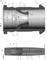
- the packaging and application system represented in FIGS. 1 and 2 comprises a container 9 containing the product to be applied, for example a makeup product such as a foundation, a mascara, a lipstick, a nail polish, or generally any cosmetic product or cosmetic compound.
- a makeup product such as a foundation, a mascara, a lipstick, a nail polish, or generally any cosmetic product or cosmetic compound.
- the terms 'bottle' or 'reservoir' may also be used to designate the recipient/container that encloses the cosmetic product, which may be liquid or pasty.
- the liquid or pasty product could be other than a cosmetic product, for example a medicinal product, a decorative product, etc.
- the container 9 may be made of glass or of a plastic synthetic material or thermoplastic material. This container 9 may be transparent or opaque.
- this container 9 is provided with a neck 90 in the upper part.
- the exterior of this neck is threaded.
- This neck comprises an upper edge delimited by the mounting plane (or seat) which the wiping device W fits onto, which will be discussed in detail below.
- the inside diameter of the neck is between 3 mm and 20 mm.
- D0 will be between 9 mm and 12 mm for the typical applications targeted.
- the applicator 3 comprises a stem 31 and an applicator head 33.
- the applicator 3 also comprises a part forming a cap suitable for screwing onto the threaded neck 90 mentioned above, as can be seen in FIG. 1 .
- the part forming a cap may be produced in two parts, namely an aesthetic piece 32 visible from the exterior, and a technical piece 34 not visible from the exterior when the applicator 3 is installed on the bottle. However, producing the cap as one piece is not excluded.
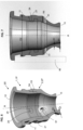
- the wiping device W comprises a first part forming a support 1, and a second part shaped as a wiping sleeve 2.
- the wiping sleeve is suitable for wiping an applicator 3 immersed in a product to be dispensed by means of the applicator. Wiping is performed during withdrawal of the applicator by mechanical interaction, i.e. friction. Wiping is carried out successively on the stem 31 and on the applicator head 33.
- the first part forming a support comprises a base with an annular flange 10 configured to rest on a mouth of the container 9.
- a first axial support shoulder 51 and a tubular portion 14 centered on axis A and intended to be mounted radially inside the mouth 94 are provided.
- the axial support shoulder 51 located under the flange 10, abuts against the upper end 37 of the mouth/neck of the bottle.
- the annular base 10 may be retained in the neck 90 either by a tight fit of the tubular portion 14 when mounted, or by clipping in place.
- the wiping sleeve 2 comprises a central passage 20, in other words an axial passage to allow the applicator to pass through and to wipe it during its passage by means of the wiping lip 15 which will be detailed below.
- the wiping sleeve 2 comprises a root portion 12 connected to the first part 1, a wiping lip 15, and an intermediate portion 13.
- the intermediate portion 13 is interposed between the root portion 12 and the wiping lip 15.
- the outer diameter of the tubular portion 14 of the first part 1 is denoted D2.
- D2 is close to D0 or, at rest, slightly greater than diameter D0 at the mouth 94 so as to provide a force fit with slight compression.
- an external shoulder 52 is provided in the lower part of the tubular portion 14. This shoulder comes to fit against the bottom of the mouth portion 90 of the bottle.
- the harpoon shape given to the lower end 53 of the tubular portion makes it possible to insert the wiping device to a locking position from which it cannot be withdrawn. This is a clip-on assembly or snap-fit assembly.
- the two shoulders 51,52 are arranged opposite one another, symmetrically relative to a plane transverse to axis A.
- the wiping sleeve 2 is generally a shape of revolution around axis A.
- the half section of wiping sleeve and/or the wiping lip as discussed herein is the present disclosure is same and identical in every plan taken around the axis A, the shape is axisymmetric.
- the wiping device is a shape of revolution around axis A.
- the wiping sleeve 2 comprises, starting from the first part and gradually approaching axis A: a root portion 12 connected to the first part, an intermediate portion 13, a wiping lip 15.
- the wiping sleeve 2 has a generally frustoconical shape.
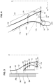
- the intermediate portion 13 is interposed between the root portion 12 and the wiping lip 15. During the wiping process, as illustrated in FIG. 5 , the intermediate portion 13 expands, i.e. moves further away from the axis, and the wiping lip 15 expands, i.e. moves even further away from the axis.
- the wiping sleeve 2 has an axial half-section which has the following profile at rest:
- the drip line is formed as a front end 19, with a radially outer bead without a skirt.
- such a front end line 19 has a concavity of downward curvature. This makes it possible to optimize the outward product-sweeping effect for the wiped product.
- the concavity is shaped as an arc of a circle or may be any other concave shape.
- the half-section is such that, at the scraping tip, the radially inner line LRI forms, at rest, an angle denoted ⁇ with the front end line LAV.
- the angle ⁇ is an acute angle, between 0° and 90°.
- the angle ⁇ may be selected within a range of between 30° and 90°.
- the angle ⁇ may be selected within a range of between 45° and 90°.
- the acute angle ( ⁇ ) between the front end line and the radially inner line LRI is between 60° and 80°.
- W1 is the tangent to the profile of the scraper tip P4 half-section nearer the radially inner line LRI. W1 is inclined relative to the main axis A, at an angle denoted ⁇ (see FIG. 4 ).
- W2 is the tangent to the profile of the half-section scraper tip P4, nearer the front end line LAV. W2 is inclined relative to the main axis A, at an angle denoted ⁇ relative to a radial direction R, namely transverse/orthogonal to axis A.
- the radially inner line LRI is a convex curve viewed from the axis. Note that in other embodiments the radially inner line LRI is flat.
- the radially outer line LRE gradually approaches the axis as one moves away from the root portion 12, this occurring in an upper portion 17a of the radially outer line LRE.
- the radially outer line LRE gradually moves away from the axis as one moves away from the intermediate portion towards the front end line in a lower portion 17b of the radially outer line LRE.
- the width E3 of the half-section, measured perpendicularly to the axis, is generically denoted E with an index k, i.e. Ek for certain specific measurements.
- the half-section is such that its width E increases from the intermediate portion 13 to the scraping tip P4.
- the width Ek is the distance which separates the radially inner line LRI from the radially outer line LRE in a direction perpendicular to axis A.
- the width E of the half-section may decrease from the root portion 12 to the intermediate portion 13.
- the width E must first decrease and then increase to the scraping tip.
- This "waist” forms a flexible area and provides possibilities for insertion and withdrawal even with a slight misalignment. This improves the ease of use.
- the width E may slightly decrease due to the relative squeezing of the half-section profile as illustrated in FIG. 5 . This reduction in width increases as one nears the scraping tip P4.
- E2 the minimum width measured at rest and at the intermediate portion 13, meaning the smallest width E along the profile is E2.
- the width E3 of the half-section, measured at the scraping tip P4, relative to the minimum width E2 is such that E3 >1.3 ⁇ E2.
- At least one air circulation vent 61 is provided in the wiping device.
- the vent 61 is arranged in the first part 1.
- a second vent 62 positioned diametrically opposite the first vent 61 may be provided.
- the vent is formed as a hole with a vent axis R6, the vent axis being oriented in a radial direction R perpendicular to the main axis A.
- vent axis forms a radial hole oriented horizontally.
- the position of the vent is fairly high, but an annular gap 96 is provided which places the radial hole in communication with the interior of the bottle 99.
- the wiping lip 15 tends to deform outwards.
- tangential direction W1 tends to straighten vertically, for example along the stem, while tangential direction W2 also straightens (see position labeled W2' ). Note that the angle ⁇ also decreases under an outwardly directed stress.
- an elastomeric polymer from the family of polyolefins or polyamides is chosen for example.
- a food-safe material is chosen.
- the choice of material is made to minimize creep phenomena, because most of the time the stem is inserted into the wiping sleeve, and consequently the wiping lip is not at rest the vast majority of the time during the user utilization stage of life.
- a bead 141 which protrudes radially outwards all around the tubular portion 14. This bead is squeezed by force-fitting the wiping device into the neck of the bottle. This compressed mounting ensures that the wiping device is held in place.
- annular shape that is slightly set back, namely a shallow groove 142 which allows ensuring that air can reach at least one vent 61, 62 even in the event of specific stresses or according to manufacturing tolerances and process variations.
- the wiping device is dual-material: the first part 1 forming a support is a first piece 1P made of a first material and the second part forming a wiping sleeve is a second piece 2P made of a second material.
- the second material is more flexible than the first material.
- the rigidity of the first piece enables forceful insertion into the neck of the bottle and retention due to the bead 11 whose diameter D2 at rest is slightly greater than the inside diameter of the neck D0 . Note that it is not excluded to have a bead provided in the second piece (denoted 21 ) that is also in tight contact with the inside diameter of the neck.
- the wiping lip 15 is formed in the second piece 2P.
- the geometry of the wiping lip 15 is in accordance with what has been described for the first embodiment.
- the dimensions and in particular the transverse thickness of the wiping sleeve notably the ratios E3 versus E, the values and ratios given for the first embodiment also apply here.
- vents 61 62 are formed in the second piece 2P.
- their axis R6 is perpendicular to the main axis, in other words the vent holes are oriented horizontally in the normal position of use of the bottle and applicator.
- the first piece comprises an inner tubular portion 54 intended to be covered by an outer tubular portion 55 coming from the second overmolded material.
- the overlap occurs over a height of a few millimeters, say between 3 and 10 millimeters.
- two diametral studs 24 are provided which each come to be received in a corresponding hole 25 made in the first piece.
- the studs and corresponding holes 24,25 are located at the area of overlap between the inner tubular portion 54 and the outer tubular portion 55.
- the radial thickness E of the wiping device at the overlap between the first piece and the second piece remains controlled, for example less than 3 x E2 or even 2.5 x E2, or even less than 1.5 x E3.
- the fluid plastic second material becomes lodged inside the holes and cavities provided in the first piece, and after the material sets, the first piece can no longer be separated from the second piece due to the nesting of the complementary shapes.
- the wiping device W is produced in two pieces, each having its own material and a specific flexibility.
- the principle of overmolding described in the second embodiment also applies to this third embodiment.
- This third embodiment is distinguished by the presence of a skirt 150 which forms the drip edge 18.
- the skirt extends cylindrically downwards from the wiping lip, with a diameter greater than that prevailing at the scraper tip P4.
- the thickness E5 of the cylindrical skirt may be close to the minimum thickness E2 of the wiping sleeve.
- E3 may be approximately two times E2.
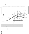
- the dotted line represents the geometry of the stem 31 which has a transverse dimension wider than the available opening at rest at the scraping tip P4.
- Dimension D1 is characteristic of the space available between the stem and the neck of the bottle. In practice this is quite small, typically less than 3 mm.
- the diameter of the stem D3 is around 4 to 6 mm.
- the entire function of the wiping sleeve must be contained within the annular gap of dimension D1 around the stem inside the neck of the bottle.
- this skirt As illustrated in FIG. 11 , management of the air flow and of the flow of wiped product can be improved by the presence of this skirt.
- the wiped product descends on the inner face 151 of the skirt, while air rises between the outer face 152 of the skirt and the neck of the bottle.
- the segregation between the liquid product and the air avoids any sputtering and splattering effect during the possibly rapid insertion and withdrawal of the applicator.
- this solution allows better performance when the bottle is no longer vertical but is substantially tilted.
- the skirt 150 ensures good separation between the flow of air and the flow of product and makes it possible to avoid any splattering.
- the skirt allows maintaining sufficient separation between the flow of air and the flow of liquid even when tilted or during shaking and/or dynamic movements.
- the radially inner line LRI is more or less straight.
- the wiping device W is produced in two pieces, each having its own material and a specific flexibility.
- the overmolding here makes use of a plurality of fingers 8 from the first piece 1P. Along the circumferential direction, each pair of fingers 8 defines an empty space between these two fingers, intended to be filled with the second polymer material during overmolding.
- the fingers 8 follow the general conical orientation of the wiping sleeve.
- the fingers therefore extend downwards from the root portion 12.
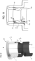
- Each of the fingers ends in a protrusion 65 which forms a hook for the complementary part of the second material which will catch thereon at the interface (portion denoted 66 in FIG. 13 ).
- the fluid plastic material of the second material lodges inside the free spaces between the fingers 8 .
- the material of the second material then forms fingers 82 extending upwards, complementary to the first fingers 8 .
- formed by the second material is a conical ferrule 68 of small thickness which comes to fill the space left free inside, up to a level denoted 67.
- the radially outer line LRE is defined by the descending fingers 8 of the first piece, while the radially inner line LRI is delimited by the upward fingers 82 of the second piece and the ferrule 68.
- the overmolding fingers 8 are invisible from the upper side of the axial passage 20 of the wiping sleeve. Once the wiping device has been inserted into the bottle, the technical elements of the overmolding are no longer visible.
- the thickness E3 measured at the scraping tip is approximately 50% greater than the thickness E2 measured at the minimum cross-section, i.e. at the overmolding protrusions.
- the device may further comprise a reinforcing ring 5 arranged behind the lip.
- the reinforcing ring 5 may be a shape of revolution around axis A.
- the reinforcing ring 5 is housed behind the narrowest part of the wiping sleeve, namely at least at the intermediate portion 13.
- the reinforcing ring 5 supplements the single-material piece detailed above concerning the first embodiment.
- the reinforcing ring 5 may be a metal ring, for example of stainless steel.
- the reinforcing ring may be a ring of polymer plastic.
- the device may further comprise a toroidal spring 50.
- a radially outer groove 58 is formed slightly above the wiping lip 15. This radially outer groove 58 is intended to receive the toroidal spring 50.
- the toroidal spring 50 is a closed-loop coil spring and the toroidal spring 50 extends in a circle around axis A.
- width E3 of the half-section measured perpendicularly to the axis at the scraping tip P4, relative to the minimum width E2 measured at the intermediate portion 13, is such that E3 > 1.3 x E2.
- the drip edge 18 is formed here by an outer tip 26.
- the angle ⁇ between the front end line LAV and the radially inner line LRI is about 100° to 110°
- the angle ⁇ between the front end line and the radially inner line LRI may be between 80° and 120°; it may preferably also be between 90° and 110°.
- the material of the toroidal spring 50 may be stainless steel or a plastic material with good elasticity.
- the wiping lip 15 has a shape of revolution around axis A and extends circumferentially identically over 360°. This provides equilibrium and regularity in the wiping forces in the circumferential direction. There is no singular point that can generate a residual trace on the stem or disequilibrium in the material on the applicator head.
Landscapes
- Containers And Packaging Bodies Having A Special Means To Remove Contents (AREA)
- Coating Apparatus (AREA)
- Closures For Containers (AREA)
- Nozzles (AREA)
Claims (14)
- Abstreifvorrichtung (W) für einen Produktapplikator, insbesondere einen Kosmetikproduktapplikator, wobei die Vorrichtung eine Achse A hat und aufweist:einen ersten Teil, der einen Halter (1) ausbildet,einen zweiten Teil, der als eine Abstreifmanschette (2) ausgebildet ist, wobei die Abstreifmanschette zum Abstreifen eines Schafts eines Applikators (3) geeignet ist, der mittels des Applikators in ein Produkt, das abgegeben werden soll, eingetaucht ist,wobei der erste Teil einen Halter ausbildet, der eine ringförmige Basis (10) die konfiguriert ist, um auf einer Mündung eines Produktbehälts (9) zu ruhen, mit einem axialen Halteflansch (51) und einem rohrförmigen Abschnitt (14), die auf die Achse A zentriert sind und dazu gedacht sind, radial innerhalb der Mündung montiert zu werden, aufweist,wobei die Abstreifmanschette (2) einen mit dem ersten Teil verbundenen Stammabschnitt (12), eine Abstreiflippe (15) und einen zwischen dem Stammabschnitt (12) und der Abstreiflippe (15) eingefügten Zwischenabschnitt (13) aufweist,wobei die Abstreifmanschette (2) einen zentralen Durchgang (20) aufweist,wobei die Abstreifmanschette im Allgemeinen eine Rotationsform um die Achse A mit einem Halbschnitt hat, der in Ruhe das folgende Profil hat:- eine radial innere Leitung (LRI), die sich allmählich der Achse nähert, wenn man sich von dem Stammabschnitt (12) weg bewegt,- eine Abstreifspitze (P4), die an der Stelle am nächsten zu der Achse der Abstreiflippe gelegen ist,- eine vordere Endleitung (LAV), die sich von der Abstreifspitze radial nach außen erstreckt,- eine radial äußere Leitung (LRE), die sich allmählich der Achse nähert, wenn man sich dabei wenigstens von dem Stammabschnitt (12) zu dem Zwischenabschnitt (13) von dem Stammabschnitt (12) weg bewegt,- eine Tropfleitung (LEG), die eine Tropfkante (18) definiert, die mit der vorderen Endleitung und mit der radial äußeren Leitung verbunden ist,wobei der Halbschnitt derart ist, dass seine Breite E senkrecht zu der Achse gemessen von dem Zwischenabschnitt zu der Abstreifspitze (P4) zunimmt,wobei der Halbschnitt derart ist, dass die radial innere Leitung (LRI) einen spitzen Winkel (β) mit der vorderen Endleitung (LAV) an der Abstreifspitze bildet.
- Abstreifvorrichtung nach Anspruch 1, wobei die Breite E3 des Halbschnitts senkrecht zu der Achse an der Abstreifspitze (P4) gemessen relativ zu der minimalen Breite E2 an dem Zwischenabschnitt (13) gemessen derart ist, dass E3 > 1,3 x E2, vorzugsweise E3 > 1,4 x E2 und insbesondere E3 > 1,5 x E2.
- Abstreifvorrichtung nach einem der Ansprüche 1 bis 2, wobei die Breite E des Halbschnitts von dem Stammabschnitt (12) zu dem Zwischenabschnitt (13) abnimmt und somit einen Zwischenabschnitt bildet.
- Abstreifvorrichtung nach einem der Ansprüche 1 bis 3, wobei die Tropfkante eine Schürze (150) bildet, die sich als ein distaler Ring erstreckt, der relativ zu dem Stammabschnitt nach unten gerichtet ist.
- Abstreifvorrichtung nach einem der Ansprüche 1 bis 4, wobei wenigstens eine Zirkulationslüftungsöffnung (61; 62) in der Abstreifvorrichtung bereitgestellt ist.
- Abstreifvorrichtung nach Anspruch 5, wobei die Lüftungsöffnung in dem ersten Teil angeordnet ist.
- Abstreifvorrichtung nach Anspruch 5, wobei die Lüftungsöffnung als ein Loch mit einer Lüftungslochachse ausgebildet ist, wobei die Lüftungslochachse in einer Radialrichtung (R) senkrecht zu der Hauptachse (A) orientiert ist.
- Abstreifvorrichtung nach einem der Ansprüche 1 bis 7, wobei die vordere Endleitung (19) eine Höhlung mit einer Abwärtskrümmung hat.
- Abstreifvorrichtung nach einem der Ansprüche 1 bis 8, die wenigstens um die Lippe herum einen Verstärkungsring (5) aufweist.
- Abstreifvorrichtung nach einem der Ansprüche 1 bis 7, wobei der spitze Winkel (β) zwischen der vorderen Endleitung und der radial inneren Leitung (LRI) zwischen 60° und 80° liegt.
- Abstreifvorrichtung nach einem der Ansprüche 1 bis 7, dadurch gekennzeichnet, dass sie aus einem Material, d.h. einem einzigen Material, hergestellt ist.
- Abstreifvorrichtung nach einem der Ansprüche 1 bis 7, dadurch gekennzeichnet, dass sie aus zwei Materialien ist, wobei der erste Teil einen Halter, der ein aus einem ersten Material hergestelltes erstes Stück (1P) ist, ausbildet und der zweite Teil einen Abstreifmanschette, der ein aus einem zweiten Material hergestelltes zweites Stück (2P) ist, ausbildet.
- Abstreifvorrichtung nach Anspruch 12, wobei komplementäre Umspritzformen (24, 25; 8, 82, 65) bereitgestellt sind.
- Abstreifvorrichtung nach Anspruch 12, wobei Umspritzfinger (8) bereitgestellt sind, die von der Oberseite des Axialdurchgangs der Abstreifmanschette unsichtbar sind.
Applications Claiming Priority (1)
| Application Number | Priority Date | Filing Date | Title |
|---|---|---|---|
| FR2109753A FR3126859B1 (fr) | 2021-09-16 | 2021-09-16 | Essoreur pour applicateur de produit cosmetique |
Publications (3)
| Publication Number | Publication Date |
|---|---|
| EP4151121A2 EP4151121A2 (de) | 2023-03-22 |
| EP4151121A3 EP4151121A3 (de) | 2023-05-24 |
| EP4151121B1 true EP4151121B1 (de) | 2025-05-21 |
Family
ID=78332918
Family Applications (1)
| Application Number | Title | Priority Date | Filing Date |
|---|---|---|---|
| EP22193829.3A Active EP4151121B1 (de) | 2021-09-16 | 2022-09-05 | Abstreifvorrichtung für kosmetikapplikatoren |
Country Status (5)
| Country | Link |
|---|---|
| US (1) | US12303009B2 (de) |
| EP (1) | EP4151121B1 (de) |
| CN (1) | CN115813105A (de) |
| BR (1) | BR102022018458A2 (de) |
| FR (1) | FR3126859B1 (de) |
Families Citing this family (1)
| Publication number | Priority date | Publication date | Assignee | Title |
|---|---|---|---|---|
| FR3163538A1 (fr) | 2024-06-19 | 2025-12-26 | Pochet | Agencement essoreur, dispositif de conditionnement d’un produit cosmetique incluant l’agencement et assemblage du dispositif utilisant un connecteur a deux etages |
Family Cites Families (5)
| Publication number | Priority date | Publication date | Assignee | Title |
|---|---|---|---|---|
| US5873669A (en) * | 1997-05-02 | 1999-02-23 | Bic Corporation | Wiper insert |
| US7278798B1 (en) * | 2006-06-16 | 2007-10-09 | Risdon International, Inc. | Wiper for cosmetics bottle |
| FR3027496B1 (fr) * | 2014-10-24 | 2016-12-30 | Oreal | Dispositif de conditionnement et d'application |
| FR3089768B1 (fr) * | 2018-12-13 | 2022-02-18 | Qualipac Sa | Organe d’essorage pour un dispositif de conditionnement et d’application d’un produit cosmétique |
| FR3090291B1 (fr) * | 2018-12-19 | 2021-04-16 | Oreal | Dispositif de conditionnement d’un produit cosmétique |
-
2021
- 2021-09-16 FR FR2109753A patent/FR3126859B1/fr active Active
-
2022
- 2022-09-05 EP EP22193829.3A patent/EP4151121B1/de active Active
- 2022-09-14 US US17/944,785 patent/US12303009B2/en active Active
- 2022-09-14 CN CN202211113708.9A patent/CN115813105A/zh active Pending
- 2022-09-15 BR BR102022018458-5A patent/BR102022018458A2/pt not_active Application Discontinuation
Also Published As
| Publication number | Publication date |
|---|---|
| US20230078841A1 (en) | 2023-03-16 |
| BR102022018458A2 (pt) | 2023-03-28 |
| US12303009B2 (en) | 2025-05-20 |
| FR3126859A1 (fr) | 2023-03-17 |
| CN115813105A (zh) | 2023-03-21 |
| EP4151121A3 (de) | 2023-05-24 |
| FR3126859B1 (fr) | 2023-12-22 |
| EP4151121A2 (de) | 2023-03-22 |
Similar Documents
| Publication | Publication Date | Title |
|---|---|---|
| US6331085B1 (en) | Container-applicator system for material for the skin | |
| US9004075B2 (en) | Wiper for a cosmetic container | |
| EP1897623A2 (de) | Spenderanordnung für einen Flüssigkeitsspenderbehälter und Montageverfahren dafür | |
| JP2003125842A (ja) | 物質を包装しおよび/またはこれを睫毛および/または眉毛に適用するデバイスおよびメイクアップを適用する方法 | |
| EP3843584B1 (de) | Applikator zum applizieren eines produktes, insbesondere eines kosmetischen produktes | |
| US20200187625A1 (en) | Wiper member for a device for the packaging and application of a cosmetic product | |
| EP4151121B1 (de) | Abstreifvorrichtung für kosmetikapplikatoren | |
| US10835013B2 (en) | Container with dispensing tip | |
| CN116782793A (zh) | 化妆品包装装置 | |
| CN101031219A (zh) | 化妆品分配器上的改进 | |
| WO2023030709A1 (en) | Packaging device for a refill fitted with a pump | |
| EP4327693A1 (de) | Kosmetikbehälter mit automatischer tropfvorrichtung | |
| KR20230047037A (ko) | 화장품용 재충전 가능한 용기 디바이스를 위한 케이싱 및 관련 용기 디바이스 | |
| CN114761138A (zh) | 用于化妆产品的可再填充的包装组件 | |
| US20150136812A1 (en) | Dispenser | |
| CN113163920A (zh) | 旨在装配在化妆品产品容器上的擦拭件 | |
| JP2017500941A (ja) | 包装および塗布デバイス | |
| EP0290431B1 (de) | Ein zusammenbau und verfahren zum befestigen und abdichten eines verteilers an einem mit einem flansch versehenen behälter | |
| EP3727083B1 (de) | Applikatorelement zum auftragen eines produkts, insbesondere eines kosmetischen produkts, und anordnung zum verpacken und auftragen eines produkts, das besagtes auftragselement enthält | |
| EP3389441B1 (de) | Applikator zum auftragen eines kosmetik-, make-up- oder pflegeprodukts auf die wimpern und/oder augenlider | |
| KR20170117134A (ko) | 배출되는 제품을 위한 패키징 장치 | |
| CN110267565B (zh) | 容器 | |
| CN114620346B (zh) | 用于液体产品施用器的刮拭器 | |
| CN112368083A (zh) | 用于流体产品的容器 | |
| CN111556717A (zh) | 用于利用相同部件制造化妆品容器的化妆品容器系统 |
Legal Events
| Date | Code | Title | Description |
|---|---|---|---|
| PUAI | Public reference made under article 153(3) epc to a published international application that has entered the european phase |
Free format text: ORIGINAL CODE: 0009012 |
|
| STAA | Information on the status of an ep patent application or granted ep patent |
Free format text: STATUS: THE APPLICATION HAS BEEN PUBLISHED |
|
| AK | Designated contracting states |
Kind code of ref document: A2 Designated state(s): AL AT BE BG CH CY CZ DE DK EE ES FI FR GB GR HR HU IE IS IT LI LT LU LV MC MK MT NL NO PL PT RO RS SE SI SK SM TR |
|
| PUAL | Search report despatched |
Free format text: ORIGINAL CODE: 0009013 |
|
| AK | Designated contracting states |
Kind code of ref document: A3 Designated state(s): AL AT BE BG CH CY CZ DE DK EE ES FI FR GB GR HR HU IE IS IT LI LT LU LV MC MK MT NL NO PL PT RO RS SE SI SK SM TR |
|
| RIC1 | Information provided on ipc code assigned before grant |
Ipc: A45D 40/26 20060101AFI20230420BHEP |
|
| STAA | Information on the status of an ep patent application or granted ep patent |
Free format text: STATUS: REQUEST FOR EXAMINATION WAS MADE |
|
| 17P | Request for examination filed |
Effective date: 20231120 |
|
| RBV | Designated contracting states (corrected) |
Designated state(s): AL AT BE BG CH CY CZ DE DK EE ES FI FR GB GR HR HU IE IS IT LI LT LU LV MC MK MT NL NO PL PT RO RS SE SI SK SM TR |
|
| GRAP | Despatch of communication of intention to grant a patent |
Free format text: ORIGINAL CODE: EPIDOSNIGR1 |
|
| STAA | Information on the status of an ep patent application or granted ep patent |
Free format text: STATUS: GRANT OF PATENT IS INTENDED |
|
| INTG | Intention to grant announced |
Effective date: 20250228 |
|
| GRAS | Grant fee paid |
Free format text: ORIGINAL CODE: EPIDOSNIGR3 |
|
| GRAA | (expected) grant |
Free format text: ORIGINAL CODE: 0009210 |
|
| STAA | Information on the status of an ep patent application or granted ep patent |
Free format text: STATUS: THE PATENT HAS BEEN GRANTED |
|
| AK | Designated contracting states |
Kind code of ref document: B1 Designated state(s): AL AT BE BG CH CY CZ DE DK EE ES FI FR GB GR HR HU IE IS IT LI LT LU LV MC MK MT NL NO PL PT RO RS SE SI SK SM TR |
|
| REG | Reference to a national code |
Ref country code: GB Ref legal event code: FG4D |
|
| REG | Reference to a national code |
Ref country code: CH Ref legal event code: EP |
|
| REG | Reference to a national code |
Ref country code: DE Ref legal event code: R096 Ref document number: 602022014885 Country of ref document: DE |
|
| REG | Reference to a national code |
Ref country code: IE Ref legal event code: FG4D |
|
| REG | Reference to a national code |
Ref country code: NL Ref legal event code: MP Effective date: 20250521 |
|
| PG25 | Lapsed in a contracting state [announced via postgrant information from national office to epo] |
Ref country code: FI Free format text: LAPSE BECAUSE OF FAILURE TO SUBMIT A TRANSLATION OF THE DESCRIPTION OR TO PAY THE FEE WITHIN THE PRESCRIBED TIME-LIMIT Effective date: 20250521 Ref country code: ES Free format text: LAPSE BECAUSE OF FAILURE TO SUBMIT A TRANSLATION OF THE DESCRIPTION OR TO PAY THE FEE WITHIN THE PRESCRIBED TIME-LIMIT Effective date: 20250521 Ref country code: PT Free format text: LAPSE BECAUSE OF FAILURE TO SUBMIT A TRANSLATION OF THE DESCRIPTION OR TO PAY THE FEE WITHIN THE PRESCRIBED TIME-LIMIT Effective date: 20250922 |
|
| REG | Reference to a national code |
Ref country code: LT Ref legal event code: MG9D |
|
| PG25 | Lapsed in a contracting state [announced via postgrant information from national office to epo] |
Ref country code: GR Free format text: LAPSE BECAUSE OF FAILURE TO SUBMIT A TRANSLATION OF THE DESCRIPTION OR TO PAY THE FEE WITHIN THE PRESCRIBED TIME-LIMIT Effective date: 20250822 Ref country code: NO Free format text: LAPSE BECAUSE OF FAILURE TO SUBMIT A TRANSLATION OF THE DESCRIPTION OR TO PAY THE FEE WITHIN THE PRESCRIBED TIME-LIMIT Effective date: 20250821 |
|
| PG25 | Lapsed in a contracting state [announced via postgrant information from national office to epo] |
Ref country code: PL Free format text: LAPSE BECAUSE OF FAILURE TO SUBMIT A TRANSLATION OF THE DESCRIPTION OR TO PAY THE FEE WITHIN THE PRESCRIBED TIME-LIMIT Effective date: 20250521 Ref country code: NL Free format text: LAPSE BECAUSE OF FAILURE TO SUBMIT A TRANSLATION OF THE DESCRIPTION OR TO PAY THE FEE WITHIN THE PRESCRIBED TIME-LIMIT Effective date: 20250521 |
|
| PG25 | Lapsed in a contracting state [announced via postgrant information from national office to epo] |
Ref country code: BG Free format text: LAPSE BECAUSE OF FAILURE TO SUBMIT A TRANSLATION OF THE DESCRIPTION OR TO PAY THE FEE WITHIN THE PRESCRIBED TIME-LIMIT Effective date: 20250521 |
|
| PG25 | Lapsed in a contracting state [announced via postgrant information from national office to epo] |
Ref country code: HR Free format text: LAPSE BECAUSE OF FAILURE TO SUBMIT A TRANSLATION OF THE DESCRIPTION OR TO PAY THE FEE WITHIN THE PRESCRIBED TIME-LIMIT Effective date: 20250521 |
|
| PGFP | Annual fee paid to national office [announced via postgrant information from national office to epo] |
Ref country code: FR Payment date: 20250916 Year of fee payment: 4 |
|
| PG25 | Lapsed in a contracting state [announced via postgrant information from national office to epo] |
Ref country code: RS Free format text: LAPSE BECAUSE OF FAILURE TO SUBMIT A TRANSLATION OF THE DESCRIPTION OR TO PAY THE FEE WITHIN THE PRESCRIBED TIME-LIMIT Effective date: 20250821 |
|
| PG25 | Lapsed in a contracting state [announced via postgrant information from national office to epo] |
Ref country code: IS Free format text: LAPSE BECAUSE OF FAILURE TO SUBMIT A TRANSLATION OF THE DESCRIPTION OR TO PAY THE FEE WITHIN THE PRESCRIBED TIME-LIMIT Effective date: 20250921 |
|
| PG25 | Lapsed in a contracting state [announced via postgrant information from national office to epo] |
Ref country code: LV Free format text: LAPSE BECAUSE OF FAILURE TO SUBMIT A TRANSLATION OF THE DESCRIPTION OR TO PAY THE FEE WITHIN THE PRESCRIBED TIME-LIMIT Effective date: 20250521 |
|
| REG | Reference to a national code |
Ref country code: AT Ref legal event code: MK05 Ref document number: 1796016 Country of ref document: AT Kind code of ref document: T Effective date: 20250521 |
|
| PG25 | Lapsed in a contracting state [announced via postgrant information from national office to epo] |
Ref country code: SM Free format text: LAPSE BECAUSE OF FAILURE TO SUBMIT A TRANSLATION OF THE DESCRIPTION OR TO PAY THE FEE WITHIN THE PRESCRIBED TIME-LIMIT Effective date: 20250521 Ref country code: DK Free format text: LAPSE BECAUSE OF FAILURE TO SUBMIT A TRANSLATION OF THE DESCRIPTION OR TO PAY THE FEE WITHIN THE PRESCRIBED TIME-LIMIT Effective date: 20250521 Ref country code: AT Free format text: LAPSE BECAUSE OF FAILURE TO SUBMIT A TRANSLATION OF THE DESCRIPTION OR TO PAY THE FEE WITHIN THE PRESCRIBED TIME-LIMIT Effective date: 20250521 |
|
| PG25 | Lapsed in a contracting state [announced via postgrant information from national office to epo] |
Ref country code: CZ Free format text: LAPSE BECAUSE OF FAILURE TO SUBMIT A TRANSLATION OF THE DESCRIPTION OR TO PAY THE FEE WITHIN THE PRESCRIBED TIME-LIMIT Effective date: 20250521 |
|
| PG25 | Lapsed in a contracting state [announced via postgrant information from national office to epo] |
Ref country code: EE Free format text: LAPSE BECAUSE OF FAILURE TO SUBMIT A TRANSLATION OF THE DESCRIPTION OR TO PAY THE FEE WITHIN THE PRESCRIBED TIME-LIMIT Effective date: 20250521 |
|
| PG25 | Lapsed in a contracting state [announced via postgrant information from national office to epo] |
Ref country code: SK Free format text: LAPSE BECAUSE OF FAILURE TO SUBMIT A TRANSLATION OF THE DESCRIPTION OR TO PAY THE FEE WITHIN THE PRESCRIBED TIME-LIMIT Effective date: 20250521 |
|
| PG25 | Lapsed in a contracting state [announced via postgrant information from national office to epo] |
Ref country code: IT Free format text: LAPSE BECAUSE OF FAILURE TO SUBMIT A TRANSLATION OF THE DESCRIPTION OR TO PAY THE FEE WITHIN THE PRESCRIBED TIME-LIMIT Effective date: 20250521 |
|
| PG25 | Lapsed in a contracting state [announced via postgrant information from national office to epo] |
Ref country code: RO Free format text: LAPSE BECAUSE OF FAILURE TO SUBMIT A TRANSLATION OF THE DESCRIPTION OR TO PAY THE FEE WITHIN THE PRESCRIBED TIME-LIMIT Effective date: 20250521 |
|
| PLBE | No opposition filed within time limit |
Free format text: ORIGINAL CODE: 0009261 |
|
| STAA | Information on the status of an ep patent application or granted ep patent |
Free format text: STATUS: NO OPPOSITION FILED WITHIN TIME LIMIT |