EP4148503B1 - Vorrichtung zur manuellen steuerung eines mechanismus für eine uhr - Google Patents
Vorrichtung zur manuellen steuerung eines mechanismus für eine uhr Download PDFInfo
- Publication number
- EP4148503B1 EP4148503B1 EP21196126.3A EP21196126A EP4148503B1 EP 4148503 B1 EP4148503 B1 EP 4148503B1 EP 21196126 A EP21196126 A EP 21196126A EP 4148503 B1 EP4148503 B1 EP 4148503B1
- Authority
- EP
- European Patent Office
- Prior art keywords
- corrector
- manual
- actuators
- timepiece
- actuator
- Prior art date
- Legal status (The legal status is an assumption and is not a legal conclusion. Google has not performed a legal analysis and makes no representation as to the accuracy of the status listed.)
- Active
Links
Images

Classifications
-
- G—PHYSICS
- G04—HOROLOGY
- G04B—MECHANICALLY-DRIVEN CLOCKS OR WATCHES; MECHANICAL PARTS OF CLOCKS OR WATCHES IN GENERAL; TIME PIECES USING THE POSITION OF THE SUN, MOON OR STARS
- G04B19/00—Indicating the time by visual means
- G04B19/22—Arrangements for indicating different local apparent times; Universal time pieces
- G04B19/23—Arrangements for indicating different local apparent times; Universal time pieces by means of additional hands or additional pairs of hands
- G04B19/235—Arrangements for indicating different local apparent times; Universal time pieces by means of additional hands or additional pairs of hands mechanisms for correcting the additional hand or hands
-
- G—PHYSICS
- G04—HOROLOGY
- G04B—MECHANICALLY-DRIVEN CLOCKS OR WATCHES; MECHANICAL PARTS OF CLOCKS OR WATCHES IN GENERAL; TIME PIECES USING THE POSITION OF THE SUN, MOON OR STARS
- G04B27/00—Mechanical devices for setting the time indicating means
- G04B27/001—Internal gear therefor, e.g. for setting the second hand or for setting several clockworks
-
- G—PHYSICS
- G04—HOROLOGY
- G04B—MECHANICALLY-DRIVEN CLOCKS OR WATCHES; MECHANICAL PARTS OF CLOCKS OR WATCHES IN GENERAL; TIME PIECES USING THE POSITION OF THE SUN, MOON OR STARS
- G04B19/00—Indicating the time by visual means
- G04B19/22—Arrangements for indicating different local apparent times; Universal time pieces
-
- G—PHYSICS
- G04—HOROLOGY
- G04B—MECHANICALLY-DRIVEN CLOCKS OR WATCHES; MECHANICAL PARTS OF CLOCKS OR WATCHES IN GENERAL; TIME PIECES USING THE POSITION OF THE SUN, MOON OR STARS
- G04B19/00—Indicating the time by visual means
- G04B19/24—Clocks or watches with date or week-day indicators, i.e. calendar clocks or watches; Clockwork calendars
- G04B19/243—Clocks or watches with date or week-day indicators, i.e. calendar clocks or watches; Clockwork calendars characterised by the shape of the date indicator
- G04B19/247—Clocks or watches with date or week-day indicators, i.e. calendar clocks or watches; Clockwork calendars characterised by the shape of the date indicator disc-shaped
- G04B19/25—Devices for setting the date indicators manually
-
- G—PHYSICS
- G04—HOROLOGY
- G04B—MECHANICALLY-DRIVEN CLOCKS OR WATCHES; MECHANICAL PARTS OF CLOCKS OR WATCHES IN GENERAL; TIME PIECES USING THE POSITION OF THE SUN, MOON OR STARS
- G04B27/00—Mechanical devices for setting the time indicating means
- G04B27/004—Mechanical devices for setting the time indicating means having several simultaneous functions, e.g. stopping or starting the clockwork or the hands
-
- G—PHYSICS
- G04—HOROLOGY
- G04B—MECHANICALLY-DRIVEN CLOCKS OR WATCHES; MECHANICAL PARTS OF CLOCKS OR WATCHES IN GENERAL; TIME PIECES USING THE POSITION OF THE SUN, MOON OR STARS
- G04B27/00—Mechanical devices for setting the time indicating means
- G04B27/005—Mechanical devices for setting the time indicating means stepwise or on determined values
Definitions
- the invention also relates to a timepiece, comprising at least one mechanism, of which at least one correction wheel set is arranged to be controlled at least by such a manual control device.
- the invention relates to the field of watch mechanisms, in particular complication mechanisms such as calendar mechanisms or time zone mechanisms, and the associated adjustment mechanisms, allowing adjustment by the user of the timepiece.
- this manual actuator When the user actuates a manual actuator associated with a corrector, in a first step, this manual actuator pushes this corrector via a stud driven into the manual actuator until it comes into contact with the bottom of the spindle correction wheel teeth. If the user continues to push the control, the corrector drives the spindle correction wheel tooth to a stop, in a second step.
- the corrector's return spring disengages the corrector from the spindle correction wheel teeth in a third step, and returns the corrector and its manual actuator to a stop in the rest position in a fourth step.
- the two opposing correctors operate in the same way, and act on the same spindle correction wheel. Therefore, if the user actuates the correctors via their manual actuators at the same time, this action can cause the spindle correction wheel teeth to break and/or other damage within the mechanism.
- the aim of the invention is to secure a correction mechanism comprising two opposing correctors acting on the same mechanism, and more precisely on the same correction wheel set, to avoid breakage when the user presses the two correction pushers at the same time.
- the invention also aims to propose an architecture of a manual control device for a correction mechanism making it possible not to prioritize a particular manual corrector actuator, so that the only consequence in the event of simultaneous actuation of the two manual corrector actuators is the absence of any correction, unlike the devices of the prior art.
- the invention relates to a device for manually controlling a mechanism for a timepiece, comprising two opposing manual corrector actuators, arranged to be operated by a user and to control the same correction wheel set in opposite direction movements, each of the two manual corrector actuators setting in motion an associated corrector comprising a beak which is configured to bear on a relief of said correction wheel set and to move said correction wheel set during a complete stroke of said manual corrector actuator under the action of the user
- said manual control device comprises an isolation mechanism arranged to prevent an action of one of the two manual corrector actuators on said correction wheel set when the other of the two manual corrector actuators is engaged and interacting with said correction wheel set, characterized in that said isolation mechanism comprises an isolator configured to be driven in rotation when one of the two manual corrector actuators is engaged, to limit the stroke of the other of the two manual actuators of the antagonistic corrector and to prevent access of its corrector associated with said correction mobile.
- the invention also relates to a timepiece, comprising at least one mechanism, of which at least one correction wheel set is arranged to be controlled at least by such a manual control device.
- said correction wheel is held in position by a jumper subjected to the action of at least one spring.
- said at least one mechanism is a spindle mechanism and said correction wheel is a spindle correction wheel.
- said at least one mechanism is a calendar mechanism and said correction wheel is a date wheel or ring.
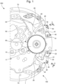
- the invention relates to a manual control device 100 of a mechanism 500 for a timepiece 1000, comprising manual corrector actuators 30, 50, which are arranged to be operated by a user, and to control the same correction wheel set 10 in movements in opposite directions.
- the invention is described here in a non-limiting application to the case of a spindle correction mechanism, illustrated by the Figure 1 , comprising two antagonistic manual corrector actuators 30, 50, which are here more particularly control pushers, which tend to rotate the correction wheel 10, which is here a spindle correction wheel, in two opposite directions (clockwise and anti-clockwise).
- a first manual corrector actuator 30 is directly operable by a user in a pushing action in a first direction A.
- the first manual corrector actuator 30 is pivotally mounted around a first articulation pin 31 driven into a plate 1 of the mechanism 500, so that under the action of the user, the first manual corrector actuator 30 pivots around the first articulation pin 31.
- the manual control device 100 also comprises a first corrector 20 articulated relative to the first manual corrector actuator 30.
- the first corrector 20 comprises a first oblong guide groove 23 configured to cooperate with the first articulation pin 31 so as to allow the articulation of the first corrector 20 relative to the first manual corrector actuator 30.
- the first oblong groove 23 is configured to guide the movement of the first corrector when the first manual corrector actuator 30 pivots, according to a rotational and translational movement.
- the first manual corrector actuator 30 comprises a first actuating stud 32, for example driven into the body of the first manual corrector actuator 30.
- the first actuating stud 32 makes it possible to transmit to the first corrector 20 the pushing action exerted on the first manual corrector actuator 30 by the user.
- the first manual corrector actuator 30 tends to be pushed back, directly or indirectly, in a second direction B opposite to the first direction A, towards an inactive rest position by a first elastic return means 22, here not limited to a spring.
- the first elastic return means 22 is formed by two independent return springs, a first spring acting on the first corrector 20 and a second spring acting on the first manual corrector actuator 30.
- the direction of rotation of the first corrector 20 corresponds to the direction of rotation of the correction wheel set 10, the first corrector 20 acting directly on the correction wheel set 10 and not via an intermediate element or gear train.
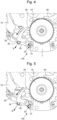
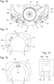
- FIG. 4 illustrates a third step consisting of the release by the user of the first manual corrector actuator 30, which, under the action of the first elastic return means 22, pivots, as does the first corrector 20 in a second direction SAH, corresponding in our exemplary embodiment to the counterclockwise direction, to cause the first beak 29 to come out of the toothing of the correction wheel 10.
- FIG. 5 illustrates a fourth step corresponding to the complete release of the first manual corrector actuator 30 and to the repositioning of the first manual corrector actuator 30, which returns to a stop in a rest position.
- the operation of the second manual corrector actuator 50 and its associated second corrector 40 is similar to the operation of the first manual corrector actuator 30 and the first corrector 20, as described with reference to figures 2 to 5
- the embodiment variants proposed for the first manual corrector actuator 30 and its first corrector 20 are also applicable to the second manual corrector actuator 50 and its second corrector 40.
- the two correctors 20, 50 are antagonistic correctors which operate in the same way, and which act on the same correction mobile 10.
- the two correctors 20, 50 act symmetrically on the same correction wheel 10.
- the manual control device 100 further comprises means for neutralizing two simultaneous opposing corrections.
- the manual control device 100 comprises an isolation mechanism, which is arranged to prohibit an action of one of the manual corrector actuators 30, 50, on the correction wheel set 10 when the other of the opposing manual corrector actuators 30, 50 is in interaction with the correction wheel set 10.
- each manual corrector actuator 30, 50 tends to be pushed directly or indirectly towards an inactive rest position by an elastic return means 22, 42, which constitutes the only elastic return means of the mechanism connecting the manual corrector actuator 30, 50 considered, to the correction mobile 10.
- each manual corrector actuator 30, 50 is articulated with a corrector 20, 40, which comprises a beak 29, 49, which is arranged to bear on a relief of the mobile of correction 10 to make it move during a complete stroke of the manual corrector actuator 30, 50, under the action of the user.
- the isolation mechanism may comprise an isolator 70, which is arranged to be driven during a movement of one of the manual corrector actuators 30, 50, and to limit the travel of the other of the manual corrector actuators 50, 30, and thus prevent access of its associated corrector 40, 20 to the correction wheel set 10.
- the isolator 70 is driven in rotation during a movement of one of the manual corrector actuators 30, 50.
- the insulator 70 is monolithic.
- the insulator 70 is in several parts articulated relative to each other.
- the insulator 70 is in several parts, which are arranged to come into contact with one another during an action by a user on one of the manual corrector actuators 30, 50.
- Such an insulator 70 is mounted to rotate about an axis perpendicular to the plate 1, and forms a safety lever making it possible to guarantee that the correctors 20, 40 do not drive the correction wheel 10 at the same time, for example the spindle correction wheel in our non-limiting application example.
- Such an isolator 70 is configured not to prioritize a manual corrector actuator 30, 50 in particular as is the case with the manual control devices of the prior art.
- the manual control device 100 according to the invention makes it possible to prioritize the manual corrector actuator actuated first by the user and not prioritize a manual corrector actuator predefined during the design.
- the manual control device according to the invention therefore allows not to prioritize the advance or recoil corrector during design.
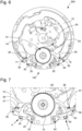
- the insulator 70 is shown in its entirety more particularly at the Figure 6 .
- FIG. 6 particularly illustrates the manual control device 100 and the isolation mechanism in the rest position, in the absence of user action, as well as the Figure 1 .
- the insulator 70 forms a rocker comprising, at its opposite ends, stop fingers 71, 72, each of the stop fingers 71, 72 being arranged to cooperate in support with a portion of the manual corrector actuators 30, 50.
- the two opposite ends of the insulator 70 have an identical shape and perform the same function.
- Each manual corrector actuator 30, 50 further comprises several support profiles making it possible to interact with the isolator 70, and more particularly with the stop fingers 71, 72, depending on the actions of the user.
- each manual corrector actuator 30, 50 comprises a first support profile 37, 57 configured to form a stop profile of the manual corrector actuator 30, 50, the first support profile 37, 57 being configured to cooperate respectively with a stop finger 71, 72 of the isolator 70.
- Each manual corrector actuator 30, 50 comprises a second support profile 36, 56 configured to form an escape profile, or a sliding profile, on which the stop finger 71, 72 of the isolator 70 slides, so as to allow at least partial rotation of a manual corrector actuator 30, 50 when the opposing manual corrector actuator 30, 50 is not actuated simultaneously, as shown more particularly in figures 8 to 9 .
- the manual corrector actuators 30, 50 are actuated simultaneously by the user.
- the manual corrector actuators 30 and 50 are actuated simultaneously, they simultaneously come into contact with the stop fingers 71, 72 of the insulator 70, at the first support profile 37, 57.
- the first support profiles 37, 57 are simultaneously pressed against a stop finger 71, 72 of the insulator 70.
- each manual corrector actuator 30, 50 exerts an opposite and identical action to the other on the insulator 70, which can rotate, rotation of the insulator 70 is not possible.
- the isolation mechanism makes it possible to prevent the two corrector nozzles 29 and 49 from interacting with the correction wheel 10 when they are activated at the same time by the user, via the manual corrector actuators 30, 50.
- the stop fingers 71, 72 have a first identical shape and the first support profiles 37, 57 have a second identical shape so that the forces exerted on the insulator 70 via the manual corrector actuators 30, 50 are substantially equivalent.
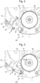
- this first manual corrector actuator 30 which is actuated. As seen previously, this first manual corrector actuator 30 actuates the corrector 20, which acts in the direction of a clockwise correction, until the corrector beak 29 comes into contact with a tooth 11 of the teeth of the correction wheel 10.
- the rotation of the manual corrector actuator 30 causes the first support profile 37 to come into contact with the first finger 71 of the insulator, then the rotation of the insulator 70 over its maximum travel.
- the support profiles 37, 36 of the manual corrector actuator 30 are configured so that the maximum stroke of the isolator 70 is reached before the corrector beak 29 comes into contact with the teeth of the correction wheel 10.
- the insulator 70 is held in the tilted position via the second support profile 36.
- the distance between the rocker 70 and the second manual corrector actuator 50 is very small, which prevents rotation of the latter and of the second correction 40 and therefore actuation of the second manual corrector actuator 50 once the first manual corrector actuator 30 is engaged. A slight play may be possible.
- the manual corrector actuators 30, 50 may have a clearance 38, 58 to free up space opposite the fingers 71, 72 of the insulator 70, thus allowing the insulator 70 to be able to tilt and reach its maximum stroke.
- the insulator 70 comprises rocker guide grooves 73 cooperating with rocker guide pins 173 carried by the plate 1 carrying the manual control device 100.
- the insulator comprises rocker pins cooperating with rocker pin guide grooves formed in the plate 1 carrying the manual control device 100.
- the insulator 70 is pivotally mounted around an axis 174 mounted on the plate 1 carrying the manual control device 100.
- the isolator 70 and the manual corrector actuators 30, 50 are coplanar in the mechanism 500.
- the isolator 70 and the manual corrector actuators 30, 50 may be positioned in different planes of the mechanism 500 so as to facilitate the integration of the control device 100.
- the isolator 70 and the manual corrector actuators 30, 50 and/or the associated correctors 20, 40 can be positioned in different planes parallel to each other of the mechanism 500 so as to facilitate the integration of the control device 100.
- the isolator 70 can cooperate with manual corrector actuators 30, 50 positioned in two different and parallel planes of the mechanism 500.
- the isolator 70 may also be used to initiate one or more additional functions upon switching of the isolator 70.
- the insulator 70 may comprise a clutch pin 74 integral with the movements of the insulator 70.
- This clutch pin 74 is in particular arranged to, during the movement of the insulator 70 initiated during a correction, move an additional mobile, for example a clutch mobile, move a lever equipped with an idler pinion, engage the correction mechanism with the hand of the timepiece, or even disengage it.
- Each manual corrector actuator 30, 50 comprises a limiting member for limiting the angular travel.
- the manual control device 100 has been shown with reference to the Figure 10 without the correctors 20, 40 described previously for better visibility. More particularly, the limiting member for limiting the angular travel is formed by a limiting groove 39, 59 provided in the body of the manual corrector actuator 30, 40 and by a limiting pin 208, 408 carried by the plate 1 carrying the manual control device 100.
- the limiting groove 39, 59 cooperates with the limiting pin 208, 408 in the following manner: in the rest position, under the influence of the first elastic return means 22 or the second elastic return means 42, the limiting groove 39, 59 bears on the limiting pin 208, 408 at a first end of the limiting groove 39, 59.
- the maximum rotational travel of the manual corrector actuator 30, 50 is defined by the second end of the limiting groove 39, 59 coming into abutment against the limiting pin 208, 408 under the thrust initiated by the user.
- each of the manual corrector actuators 30, 50 is outside the timepiece 1000. These manual corrector actuators 30, 50 thus remain within reach of the user.
- the manual corrector actuators 30, 50 are actuated by means of pushers provided in the caseband (not shown) of the timepiece 1000.
- the invention also relates to a timepiece 1000, comprising at least one mechanism 500, of which at least one correction wheel set 10 is arranged to be controlled at least by such a manual control device 100.
- the mechanism 500 is a spindle mechanism, in this case, the correction wheel 10 is a spindle correction wheel.
- the mechanism 500 is a calendar mechanism, in this case, the correction wheel 10 is a wheel, or even a ring, of the date.
- the invention is applicable to many other watch mechanisms, for which adjustment by the user is necessary or advantageous, for example and not limited to adjustment of moon phase or age, tidal state, leap year, day/night position, morning/evening position, manual counter, selection of a striking mode, adjustment of an alarm time, or other.
Landscapes
- Physics & Mathematics (AREA)
- General Physics & Mathematics (AREA)
- Mechanical Control Devices (AREA)
- Orthopedics, Nursing, And Contraception (AREA)
Claims (20)
- Manuelle Steuerungsvorrichtung (100) für einen Mechanismus (500) für eine Uhr (1000), umfassend zwei antagonistische manuelle Korrektorwirkglieder (30, 50), die so angeordnet sind, dass sie von einem Benutzer betätigt werden können und ein und dasselbe Korrekturdrehteil (10) bei Bewegungen in entgegengesetzter Richtung steuern, wobei jedes der beiden manuellen Korrektorwirkglieder (30, 50) einen zugeordneten Korrektor (20, 40) in Bewegung setzt, der einen Messschnabel (29, 49) umfasst, der so konfiguriert ist, dass er auf einem Relief (11) des Korrekturdrehteils (10) aufliegt und das Korrekturdrehteil (10) während eines vollständigen Hubs des manuellen Korrektorwirkglieds (30, 50) unter der Einwirkung des Benutzers bewegt, wobei die manuelle Steuerungsvorrichtung (100) einen Isolationsmechanismus umfasst, der so angeordnet ist, dass er eine Betätigung eines der beiden manuellen Korrektorwirkglieder (30, 50) auf das Korrekturdrehteil (10) verbietet, wenn das andere der beiden manuellen Korrektorwirkglieder (30, 50) mit dem Korrekturdrehteil (10) in Eingriff und in Wechselwirkung steht, dadurch gekennzeichnet, dass der Isolationsmechanismus einen Isolator (70) umfasst, der so konfiguriert ist, dass er bei Eingriff eines der beiden manuellen Korrektorwirkglieder (30, 50) angetrieben wird, um den Hub des anderen der beiden manuellen Korrektorwirkglieder (50, 30) zu begrenzen und den Zugriff seines zugeordneten Korrektors (40, 20) auf das Korrekturdrehteil (10) zu verhindern.
- Manuelle Steuerungsvorrichtung (100) für einen Mechanismus (500) für eine Uhr (1000) nach dem vorhergehenden Anspruch, dadurch gekennzeichnet, dass jedes der beiden manuellen Korrektorwirkglieder (30, 50) um einen Gelenkstift (31, 51) schwenkt.
- Manuelle Steuerungsvorrichtung (100) für einen Mechanismus (500) für eine Uhr (1000) nach dem vorhergehenden Anspruch, dadurch gekennzeichnet, dass jedes der beiden manuellen Korrektorwirkglieder (30, 50) ein Betätigungsklötzchen (32, 52) umfasst, der den zugeordneten Korrektor (20, 40) durch Schwenken jedes der beiden manuellen Korrektorwirkglieder (30, 50) um den Gelenkstift (31, 51) in Bewegung setzt.
- Manuelle Steuerungsvorrichtung (100) für einen Mechanismus (500) für eine Uhr (1000) nach einem der Ansprüche 2 bis 3, dadurch gekennzeichnet, dass jeder zugeordnete Korrektor (20, 40) eine längliche Führungsnut (23, 43) umfasst, die mit dem Gelenkstift (31, 51) des entsprechenden manuellen Korrektorwirkglieds (30, 50) zusammenwirkt, wobei die längliche Nut (23, 43) so konfiguriert ist, dass sie die Bewegung des zugeordneten Korrektors (20, 40) beim Schwenken des entsprechenden manuellen Korrektorwirkglieds (30, 50) führt.
- Manuelle Steuerungsvorrichtung (100) für einen Mechanismus (500) für eine Uhr (1000) nach dem vorhergehenden Anspruch, dadurch gekennzeichnet, dass die längliche Nut (23, 43) so konfiguriert ist, dass sie den zugeordneten Korrektor (20, 40) beim Schwenken des entsprechenden manuellen Korrektorwirkglieds (30, 50) in Drehung und in Translation führt.
- Manuelle Steuerungsvorrichtung (100) für einen Mechanismus (500) für eine Uhr (1000) nach einem der vorhergehenden Ansprüche, dadurch gekennzeichnet, dass mindestens eines der beiden manuellen Korrektorwirkglieder (30, 50) ein Organ zur Begrenzung des Winkelwegs umfasst.
- Manuelle Steuerungsvorrichtung (100) für einen Mechanismus (500) für eine Uhr (1000) nach dem vorhergehenden Anspruch, dadurch gekennzeichnet, dass das Organ zur Begrenzung des Winkelwegs durch eine Begrenzungsnut (39, 59), die im Körper des mindestens einen der beiden manuellen Korrektorwirkglieder (30, 40) ausgebildet ist, und durch einen Begrenzungsstift (208, 408) gebildet wird, der von einer Platine (1) getragen wird, die die manuelle Steuervorrichtung (100) trägt.
- Manuelle Steuerungsvorrichtung (100) für einen Mechanismus (500) für eine Uhr (1000) nach einem der vorhergehenden Ansprüche, dadurch gekennzeichnet, dass der Isolator (70) eine Sicherheitswippe bildet, wobei der Isolator (70) ein erstes Ende, das einen ersten Sperrfinger (71) aufweist, und ein zweites Ende umfasst, das dem ersten Ende gegenüberliegt und einen zweiten Sperrfinger (72) aufweist, wobei der erste und der zweite Sperrfinger (71, 72) so konfiguriert sind, dass sie jeweils mit einem manuellen Korrektorwirkglied (30, 50) der beiden manuellen Korrektorwirkglieder (30, 50) in Anschlag zusammenwirken.
- Manuelle Steuerungsvorrichtung (100) für einen Mechanismus (500) für eine Uhr (1000) nach Anspruch 8, dadurch gekennzeichnet, dass der erste Sperrfinger (71) und der zweite Sperrfinger (72) eine identische Form aufweisen und/oder eine identische Funktion ausführen.
- Manuelle Steuerungsvorrichtung (100) für einen Mechanismus (500) für eine Uhr (1000) nach einem der Ansprüche 8 bis 9, dadurch gekennzeichnet, dass jedes der beiden manuellen Korrektorwirkglieder (30, 50) Folgendes umfasst:- ein erstes Auflageprofil (37, 57), das so konfiguriert ist, dass es im Zusammenwirken mit dem ersten Sperrfinger (71) oder dem zweiten Sperrfinger (72) ein Anschlagprofil bildet und die Drehung des betrachteten manuellen Korrektorwirkglieds (30, 50) verbietet;- ein zweites Auflageprofil (36, 56), das so konfiguriert ist, dass es ein Hemmungsprofil bildet, auf dem der erste Sperrfinger (71) oder der zweite Sperrfinger (72) gleitet, um eine Teildrehung des betrachteten manuellen Korrektorwirkglieds (30, 50) zuzulassen.
- Manuelle Steuerungsvorrichtung (100) für einen Mechanismus (500) für eine Uhr (1000) nach Anspruch 10, dadurch gekennzeichnet, dass die ersten Auflageprofile (37, 57) der beiden manuellen Korrektorwirkglieder (30, 50) im Wesentlichen fluchtend zueinander angeordnet sind, und dass der erste Sperrfinger (71) und der zweite Sperrfinger (72) jeweils auf dem ersten Auflageprofil (37, 57) jedes der beiden manuellen Korrektorwirkglieder (30, 50) bei gleichzeitiger Betätigung jedes der beiden manuellen Korrektorwirkglieder (30, 50) durch den Benutzer aufliegen.
- Manuelle Steuerungsvorrichtung (100) für einen Mechanismus (500) für eine Uhr (1000) nach einem der Ansprüche 10 bis 11, dadurch gekennzeichnet, dass die zweiten Auflageprofile (36, 56) der beiden manuellen Korrektorwirkglieder (30, 50) derart einander gegenüberliegend angeordnet sind, dass die Verlängerung der beiden Auflageprofile (36, 56) einen spitzen Winkel bildet, dessen Scheitelpunkt des spitzen Winkels auf den Mechanismus (500) gerichtet ist.
- Manuelle Steuerungsvorrichtung (100) für einen Mechanismus (500) für eine Uhr (1000) nach einem der vorhergehenden Ansprüche, dadurch gekennzeichnet, dass der Isolator (70) monolithisch ist.
- Manuelle Steuerungsvorrichtung (100) für einen Mechanismus (500) für eine Uhr (1000) nach einem der vorhergehenden Ansprüche, dadurch gekennzeichnet, dass der Isolator (70) um eine Achse (174) schwenkbar montiert ist, die auf einer Platine (1) angebracht ist, die die manuelle Steuerungsvorrichtung (100) trägt.
- Manuelle Steuerungsvorrichtung (100) für einen Mechanismus (500) für eine Uhr (1000) nach einem der vorhergehenden Ansprüche, dadurch gekennzeichnet, dass der Isolator (70) und die beiden manuellen Korrektorwirkglieder (30, 50) koplanar sind.
- Manuelle Steuerungsvorrichtung (100) für einen Mechanismus (500) für eine Uhr (1000) nach einem der Ansprüche 1 bis 14, dadurch gekennzeichnet, dass die beiden manuellen Korrektorwirkglieder (30, 50) und/oder die zugeordneten Korrektoren (20, 40) sich in zwei verschiedenen parallelen Ebenen erstrecken.
- Manuelle Steuerungsvorrichtung (100) für einen Mechanismus (500) für eine Uhr (1000) nach einem der vorhergehenden Ansprüche, dadurch gekennzeichnet, dass sie ein erstes elastisches Rückstellmittel (22) und ein zweites elastisches Rückstellmittel (42) umfasst, wobei jedes der elastischen Rückstellmittel (22, 42) so konfiguriert ist, dass sie einen der beiden manuellen Korrektorwirkglieder (30, 50) in eine inaktive Ruheposition treiben, wobei das erste elastische Rückstellmittel (42) und/oder das zweite elastische Rückstellmittel (42) direkt mit einem der Korrektoren (20, 40) zusammenwirkt, die den beiden manuellen Korrektorwirkgliedern (30, 50) zugeordnet sind.
- Uhr (1000), die mindestens einen Mechanismus (500) umfasst, von dem mindestens ein Korrekturdrehteil (10) so angeordnet ist, dass es mindestens durch eine manuelle Steuerungsvorrichtung (100) nach einem der Ansprüche 1 bis 17 gesteuert werden kann.
- Uhr (1000) nach Anspruch 18, dadurch gekennzeichnet, dass das Korrekturdrehteil (10) durch eine Raste (60) in Position gehalten wird, die der Wirkung mindestens einer Feder (63) unterliegt.
- Uhr (1000) nach einem der Ansprüche 18 bis 19, dadurch gekennzeichnet, dass der mindestens eine Mechanismus (500) ein Spindelmechanismus ist und dass das Korrekturdrehteil (10) ein Spindelkorrekturdrehteil ist, oder dass der mindestens eine Mechanismus (500) ein Kalendermechanismus ist und dass das Korrekturdrehteil (10) ein Datumsrad oder ein Datumsring ist.
Priority Applications (5)
| Application Number | Priority Date | Filing Date | Title |
|---|---|---|---|
| EP21196126.3A EP4148503B1 (de) | 2021-09-10 | 2021-09-10 | Vorrichtung zur manuellen steuerung eines mechanismus für eine uhr |
| US17/820,259 US12411458B2 (en) | 2021-09-10 | 2022-08-17 | Device for manually controlling a mechanism for a timepiece |
| KR1020220111666A KR102697032B1 (ko) | 2021-09-10 | 2022-09-02 | 타임피스를 위한 메커니즘을 수동으로 제어하기 위한 수동 제어 디바이스 |
| JP2022141194A JP7438298B2 (ja) | 2021-09-10 | 2022-09-06 | 計時器のための機構を手動制御するデバイス |
| CN202211106052.8A CN115793427A (zh) | 2021-09-10 | 2022-09-09 | 用于手动控制钟表的机构的装置 |
Applications Claiming Priority (1)
| Application Number | Priority Date | Filing Date | Title |
|---|---|---|---|
| EP21196126.3A EP4148503B1 (de) | 2021-09-10 | 2021-09-10 | Vorrichtung zur manuellen steuerung eines mechanismus für eine uhr |
Publications (2)
| Publication Number | Publication Date |
|---|---|
| EP4148503A1 EP4148503A1 (de) | 2023-03-15 |
| EP4148503B1 true EP4148503B1 (de) | 2025-03-12 |
Family
ID=77738927
Family Applications (1)
| Application Number | Title | Priority Date | Filing Date |
|---|---|---|---|
| EP21196126.3A Active EP4148503B1 (de) | 2021-09-10 | 2021-09-10 | Vorrichtung zur manuellen steuerung eines mechanismus für eine uhr |
Country Status (5)
| Country | Link |
|---|---|
| US (1) | US12411458B2 (de) |
| EP (1) | EP4148503B1 (de) |
| JP (1) | JP7438298B2 (de) |
| KR (1) | KR102697032B1 (de) |
| CN (1) | CN115793427A (de) |
Family Cites Families (9)
| Publication number | Priority date | Publication date | Assignee | Title |
|---|---|---|---|---|
| CH250947A (fr) * | 1945-09-06 | 1947-09-30 | Graef Jean Pierre | Montre. |
| CH304969A4 (de) * | 1969-02-28 | 1970-10-15 | ||
| CH682967B5 (fr) * | 1991-10-17 | 1994-06-30 | Bulgari Gianni Spa | Dispositif d'affichage pour pièce d'horlogerie. |
| JP4409707B2 (ja) * | 1999-04-22 | 2010-02-03 | ウーテーアー・エス・アー・マニファクチュール・オロロジェール・スイス | 押しボタン機構および当該機構を装着した時計 |
| CH699785B1 (fr) * | 2008-10-23 | 2014-02-28 | Patek Philippe Sa Geneve | Pièce d'horlogerie à fuseaux horaires et à quantième. |
| CH701671A2 (fr) * | 2009-08-17 | 2011-02-28 | Gaetan Willemin | Mise à l'heure incrémentielle. |
| EP2363761B1 (de) | 2010-03-05 | 2016-05-18 | Montres Breguet SA | Vorrichtung zur Messung des Drehmoments zum Abschalten des Schlagwerks |
| US10216146B2 (en) * | 2017-07-18 | 2019-02-26 | Patek Philippe Sa Geneve | Indicator actuating organ for a timepiece |
| EP4148504B1 (de) * | 2021-09-10 | 2025-04-16 | Blancpain SA | Zeitzonenkorrekturmechanismus für uhr |
-
2021
- 2021-09-10 EP EP21196126.3A patent/EP4148503B1/de active Active
-
2022
- 2022-08-17 US US17/820,259 patent/US12411458B2/en active Active
- 2022-09-02 KR KR1020220111666A patent/KR102697032B1/ko active Active
- 2022-09-06 JP JP2022141194A patent/JP7438298B2/ja active Active
- 2022-09-09 CN CN202211106052.8A patent/CN115793427A/zh active Pending
Also Published As
| Publication number | Publication date |
|---|---|
| JP2023041028A (ja) | 2023-03-23 |
| KR102697032B1 (ko) | 2024-08-20 |
| EP4148503A1 (de) | 2023-03-15 |
| US12411458B2 (en) | 2025-09-09 |
| CN115793427A (zh) | 2023-03-14 |
| US20230084357A1 (en) | 2023-03-16 |
| JP7438298B2 (ja) | 2024-02-26 |
| KR20230038102A (ko) | 2023-03-17 |
Similar Documents
| Publication | Publication Date | Title |
|---|---|---|
| EP2012199B2 (de) | Uhr, die mit einer Vorrichtung zur Steuerung von Funktionen und/oder Stundenanzeigen ausgerüstet ist | |
| EP0548659B1 (de) | Mechanische oder elektromechanische Uhr mit einem Triebrad, das eine Anzeigevorrichtung wie eine Datumsanzeige in Bewegung setzt | |
| EP1933212B1 (de) | Uhr mit einem Schlagwerk, die einen Sperrhebel umfasst | |
| EP3144743B1 (de) | Uhrwerk mit einem datumskorrektur-mechanismus | |
| EP3483663B1 (de) | Antriebsvorrichtung für kalendersystem einer uhr | |
| EP3602202B1 (de) | Vorrichtung zur einstellung von funktionen einer uhr | |
| EP3705949B1 (de) | Drehmomentbegrenzungsmechanismus eines uhrwerks | |
| EP0075535A1 (de) | Vorrichtung zum Steuern der Funktionen einer Uhr, die mindestens den Stand einer dieser Funktionen anzeigen kann | |
| EP1933211B1 (de) | Uhr mit Schlagwerk, die einen Sperrhebel mit doppelter Funktion umfasst | |
| EP4148503B1 (de) | Vorrichtung zur manuellen steuerung eines mechanismus für eine uhr | |
| EP4148504B1 (de) | Zeitzonenkorrekturmechanismus für uhr | |
| EP3489766A1 (de) | Mechanismus zur korrektur einer bewegungsfunktion einer uhr | |
| EP1801671B1 (de) | Mit Arretierungsmitteln versehene Kalenderuhr | |
| CH691088A5 (fr) | Mécanisme de mise à l'heure d'un mouvement d'horlogerie à quantième perpétuel. | |
| CH718955A2 (fr) | Dispositif de commande manuelle d'un mécanisme pour une pièce d'horlogerie. | |
| EP4163736B1 (de) | Stopp-mechanismus für uhr | |
| EP2884345A2 (de) | Hebelfeder für uhrwerk | |
| EP4053639B1 (de) | Vorrichtung zur auswahl von uhrfunktionen | |
| CH718954A2 (fr) | Mécanisme de correction de fuseau pour une pièce d'horlogerie. | |
| EP4053640B1 (de) | Vorrichtung zur auswahl von uhrfunktionen | |
| EP4462192B1 (de) | Anzeigevorrichtung für uhrwerk | |
| EP4254075B1 (de) | Versetzte steuerungsvorrichtung eines uhrwerks einer armbanduhr und diese steuerungsvorrichtung umfassende armbanduhr | |
| EP4414792A1 (de) | Korrekturmechanismus für mindestens eine erste und zweite anzeigevorrichtung einer uhr | |
| EP4012505A1 (de) | Uhrvorrichtung mit antiblockiervorrichtung | |
| CH719563A2 (fr) | Dispositif de commande déporté d'un mouvement horloger d'une montre et montre comprenant ledit dispositif de commande. |
Legal Events
| Date | Code | Title | Description |
|---|---|---|---|
| PUAI | Public reference made under article 153(3) epc to a published international application that has entered the european phase |
Free format text: ORIGINAL CODE: 0009012 |
|
| STAA | Information on the status of an ep patent application or granted ep patent |
Free format text: STATUS: THE APPLICATION HAS BEEN PUBLISHED |
|
| AK | Designated contracting states |
Kind code of ref document: A1 Designated state(s): AL AT BE BG CH CY CZ DE DK EE ES FI FR GB GR HR HU IE IS IT LI LT LU LV MC MK MT NL NO PL PT RO RS SE SI SK SM TR |
|
| P01 | Opt-out of the competence of the unified patent court (upc) registered |
Effective date: 20230611 |
|
| STAA | Information on the status of an ep patent application or granted ep patent |
Free format text: STATUS: REQUEST FOR EXAMINATION WAS MADE |
|
| 17P | Request for examination filed |
Effective date: 20230915 |
|
| RBV | Designated contracting states (corrected) |
Designated state(s): AL AT BE BG CH CY CZ DE DK EE ES FI FR GB GR HR HU IE IS IT LI LT LU LV MC MK MT NL NO PL PT RO RS SE SI SK SM TR |
|
| GRAP | Despatch of communication of intention to grant a patent |
Free format text: ORIGINAL CODE: EPIDOSNIGR1 |
|
| STAA | Information on the status of an ep patent application or granted ep patent |
Free format text: STATUS: GRANT OF PATENT IS INTENDED |
|
| GRAS | Grant fee paid |
Free format text: ORIGINAL CODE: EPIDOSNIGR3 |
|
| GRAA | (expected) grant |
Free format text: ORIGINAL CODE: 0009210 |
|
| STAA | Information on the status of an ep patent application or granted ep patent |
Free format text: STATUS: THE PATENT HAS BEEN GRANTED |
|
| INTG | Intention to grant announced |
Effective date: 20250113 |
|
| AK | Designated contracting states |
Kind code of ref document: B1 Designated state(s): AL AT BE BG CH CY CZ DE DK EE ES FI FR GB GR HR HU IE IS IT LI LT LU LV MC MK MT NL NO PL PT RO RS SE SI SK SM TR |
|
| REG | Reference to a national code |
Ref country code: GB Ref legal event code: FG4D Free format text: NOT ENGLISH |
|
| REG | Reference to a national code |
Ref country code: CH Ref legal event code: EP |
|
| REG | Reference to a national code |
Ref country code: DE Ref legal event code: R096 Ref document number: 602021027424 Country of ref document: DE |
|
| REG | Reference to a national code |
Ref country code: IE Ref legal event code: FG4D Free format text: LANGUAGE OF EP DOCUMENT: FRENCH |
|
| PG25 | Lapsed in a contracting state [announced via postgrant information from national office to epo] |
Ref country code: RS Free format text: LAPSE BECAUSE OF FAILURE TO SUBMIT A TRANSLATION OF THE DESCRIPTION OR TO PAY THE FEE WITHIN THE PRESCRIBED TIME-LIMIT Effective date: 20250612 |
|
| PG25 | Lapsed in a contracting state [announced via postgrant information from national office to epo] |
Ref country code: FI Free format text: LAPSE BECAUSE OF FAILURE TO SUBMIT A TRANSLATION OF THE DESCRIPTION OR TO PAY THE FEE WITHIN THE PRESCRIBED TIME-LIMIT Effective date: 20250312 |
|
| PG25 | Lapsed in a contracting state [announced via postgrant information from national office to epo] |
Ref country code: ES Free format text: LAPSE BECAUSE OF FAILURE TO SUBMIT A TRANSLATION OF THE DESCRIPTION OR TO PAY THE FEE WITHIN THE PRESCRIBED TIME-LIMIT Effective date: 20250312 |
|
| REG | Reference to a national code |
Ref country code: LT Ref legal event code: MG9D |
|
| PG25 | Lapsed in a contracting state [announced via postgrant information from national office to epo] |
Ref country code: NO Free format text: LAPSE BECAUSE OF FAILURE TO SUBMIT A TRANSLATION OF THE DESCRIPTION OR TO PAY THE FEE WITHIN THE PRESCRIBED TIME-LIMIT Effective date: 20250612 |
|
| PG25 | Lapsed in a contracting state [announced via postgrant information from national office to epo] |
Ref country code: HR Free format text: LAPSE BECAUSE OF FAILURE TO SUBMIT A TRANSLATION OF THE DESCRIPTION OR TO PAY THE FEE WITHIN THE PRESCRIBED TIME-LIMIT Effective date: 20250312 |
|
| REG | Reference to a national code |
Ref country code: NL Ref legal event code: MP Effective date: 20250312 |
|
| PG25 | Lapsed in a contracting state [announced via postgrant information from national office to epo] |
Ref country code: LV Free format text: LAPSE BECAUSE OF FAILURE TO SUBMIT A TRANSLATION OF THE DESCRIPTION OR TO PAY THE FEE WITHIN THE PRESCRIBED TIME-LIMIT Effective date: 20250312 |
|
| PG25 | Lapsed in a contracting state [announced via postgrant information from national office to epo] |
Ref country code: BG Free format text: LAPSE BECAUSE OF FAILURE TO SUBMIT A TRANSLATION OF THE DESCRIPTION OR TO PAY THE FEE WITHIN THE PRESCRIBED TIME-LIMIT Effective date: 20250312 Ref country code: GR Free format text: LAPSE BECAUSE OF FAILURE TO SUBMIT A TRANSLATION OF THE DESCRIPTION OR TO PAY THE FEE WITHIN THE PRESCRIBED TIME-LIMIT Effective date: 20250613 |
|
| REG | Reference to a national code |
Ref country code: AT Ref legal event code: MK05 Ref document number: 1775496 Country of ref document: AT Kind code of ref document: T Effective date: 20250312 |
|
| PG25 | Lapsed in a contracting state [announced via postgrant information from national office to epo] |
Ref country code: NL Free format text: LAPSE BECAUSE OF FAILURE TO SUBMIT A TRANSLATION OF THE DESCRIPTION OR TO PAY THE FEE WITHIN THE PRESCRIBED TIME-LIMIT Effective date: 20250312 |
|
| PG25 | Lapsed in a contracting state [announced via postgrant information from national office to epo] |
Ref country code: SE Free format text: LAPSE BECAUSE OF FAILURE TO SUBMIT A TRANSLATION OF THE DESCRIPTION OR TO PAY THE FEE WITHIN THE PRESCRIBED TIME-LIMIT Effective date: 20250312 |
|
| REG | Reference to a national code |
Ref country code: CH Ref legal event code: U11 Free format text: ST27 STATUS EVENT CODE: U-0-0-U10-U11 (AS PROVIDED BY THE NATIONAL OFFICE) Effective date: 20251001 |
|
| PG25 | Lapsed in a contracting state [announced via postgrant information from national office to epo] |
Ref country code: SM Free format text: LAPSE BECAUSE OF FAILURE TO SUBMIT A TRANSLATION OF THE DESCRIPTION OR TO PAY THE FEE WITHIN THE PRESCRIBED TIME-LIMIT Effective date: 20250312 |
|
| PG25 | Lapsed in a contracting state [announced via postgrant information from national office to epo] |
Ref country code: PT Free format text: LAPSE BECAUSE OF FAILURE TO SUBMIT A TRANSLATION OF THE DESCRIPTION OR TO PAY THE FEE WITHIN THE PRESCRIBED TIME-LIMIT Effective date: 20250714 |
|
| PGFP | Annual fee paid to national office [announced via postgrant information from national office to epo] |
Ref country code: DE Payment date: 20250820 Year of fee payment: 5 |
|
| PG25 | Lapsed in a contracting state [announced via postgrant information from national office to epo] |
Ref country code: PL Free format text: LAPSE BECAUSE OF FAILURE TO SUBMIT A TRANSLATION OF THE DESCRIPTION OR TO PAY THE FEE WITHIN THE PRESCRIBED TIME-LIMIT Effective date: 20250312 Ref country code: IT Free format text: LAPSE BECAUSE OF FAILURE TO SUBMIT A TRANSLATION OF THE DESCRIPTION OR TO PAY THE FEE WITHIN THE PRESCRIBED TIME-LIMIT Effective date: 20250312 |
|
| PGFP | Annual fee paid to national office [announced via postgrant information from national office to epo] |
Ref country code: GB Payment date: 20250822 Year of fee payment: 5 |
|
| PG25 | Lapsed in a contracting state [announced via postgrant information from national office to epo] |
Ref country code: AT Free format text: LAPSE BECAUSE OF FAILURE TO SUBMIT A TRANSLATION OF THE DESCRIPTION OR TO PAY THE FEE WITHIN THE PRESCRIBED TIME-LIMIT Effective date: 20250312 |
|
| PGFP | Annual fee paid to national office [announced via postgrant information from national office to epo] |
Ref country code: FR Payment date: 20250820 Year of fee payment: 5 |
|
| PG25 | Lapsed in a contracting state [announced via postgrant information from national office to epo] |
Ref country code: CZ Free format text: LAPSE BECAUSE OF FAILURE TO SUBMIT A TRANSLATION OF THE DESCRIPTION OR TO PAY THE FEE WITHIN THE PRESCRIBED TIME-LIMIT Effective date: 20250312 Ref country code: EE Free format text: LAPSE BECAUSE OF FAILURE TO SUBMIT A TRANSLATION OF THE DESCRIPTION OR TO PAY THE FEE WITHIN THE PRESCRIBED TIME-LIMIT Effective date: 20250312 |
|
| PG25 | Lapsed in a contracting state [announced via postgrant information from national office to epo] |
Ref country code: RO Free format text: LAPSE BECAUSE OF FAILURE TO SUBMIT A TRANSLATION OF THE DESCRIPTION OR TO PAY THE FEE WITHIN THE PRESCRIBED TIME-LIMIT Effective date: 20250312 |
|
| PG25 | Lapsed in a contracting state [announced via postgrant information from national office to epo] |
Ref country code: SK Free format text: LAPSE BECAUSE OF FAILURE TO SUBMIT A TRANSLATION OF THE DESCRIPTION OR TO PAY THE FEE WITHIN THE PRESCRIBED TIME-LIMIT Effective date: 20250312 |
|
| PG25 | Lapsed in a contracting state [announced via postgrant information from national office to epo] |
Ref country code: IS Free format text: LAPSE BECAUSE OF FAILURE TO SUBMIT A TRANSLATION OF THE DESCRIPTION OR TO PAY THE FEE WITHIN THE PRESCRIBED TIME-LIMIT Effective date: 20250712 |