EP3489766A1 - Mechanismus zur korrektur einer bewegungsfunktion einer uhr - Google Patents
Mechanismus zur korrektur einer bewegungsfunktion einer uhr Download PDFInfo
- Publication number
- EP3489766A1 EP3489766A1 EP17203880.4A EP17203880A EP3489766A1 EP 3489766 A1 EP3489766 A1 EP 3489766A1 EP 17203880 A EP17203880 A EP 17203880A EP 3489766 A1 EP3489766 A1 EP 3489766A1
- Authority
- EP
- European Patent Office
- Prior art keywords
- corrector
- movement
- elastic member
- timepiece
- correction
- Prior art date
- Legal status (The legal status is an assumption and is not a legal conclusion. Google has not performed a legal analysis and makes no representation as to the accuracy of the status listed.)
- Pending
Links
Images

Classifications
-
- G—PHYSICS
- G04—HOROLOGY
- G04B—MECHANICALLY-DRIVEN CLOCKS OR WATCHES; MECHANICAL PARTS OF CLOCKS OR WATCHES IN GENERAL; TIME PIECES USING THE POSITION OF THE SUN, MOON OR STARS
- G04B27/00—Mechanical devices for setting the time indicating means
-
- F—MECHANICAL ENGINEERING; LIGHTING; HEATING; WEAPONS; BLASTING
- F16—ENGINEERING ELEMENTS AND UNITS; GENERAL MEASURES FOR PRODUCING AND MAINTAINING EFFECTIVE FUNCTIONING OF MACHINES OR INSTALLATIONS; THERMAL INSULATION IN GENERAL
- F16H—GEARING
- F16H55/00—Elements with teeth or friction surfaces for conveying motion; Worms, pulleys or sheaves for gearing mechanisms
- F16H55/02—Toothed members; Worms
- F16H55/17—Toothed wheels
- F16H55/18—Special devices for taking up backlash
-
- G—PHYSICS
- G04—HOROLOGY
- G04B—MECHANICALLY-DRIVEN CLOCKS OR WATCHES; MECHANICAL PARTS OF CLOCKS OR WATCHES IN GENERAL; TIME PIECES USING THE POSITION OF THE SUN, MOON OR STARS
- G04B13/00—Gearwork
- G04B13/02—Wheels; Pinions; Spindles; Pivots
-
- G—PHYSICS
- G04—HOROLOGY
- G04B—MECHANICALLY-DRIVEN CLOCKS OR WATCHES; MECHANICAL PARTS OF CLOCKS OR WATCHES IN GENERAL; TIME PIECES USING THE POSITION OF THE SUN, MOON OR STARS
- G04B35/00—Adjusting the gear train, e.g. the backlash of the arbors, depth of meshing of the gears
Definitions
- the invention relates to a mechanism for correcting a function of a movement of a timepiece and a corrector included in this mechanism.
- the invention also relates to this movement provided with such a mechanism and also on the timepiece comprising this movement.
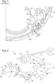
- this corrector 100 is capable of driving in a rotational movement the toothed wheel 101 which is indexed by the jumper 102 arranged in a first recess of the wheel 101 defined between two teeth of the latter and this, until the corrector 100 comes into contact with one of the two stops.
- such a corrector 100 is provided with a rigid free end 105 for transmitting a movement which is intended to come into contact with a tooth of this toothed wheel 101 so as to cause a rotational movement of the latter.
- this end 105 has a sufficient stroke to position a slope of the head of the jumper 102 on a vertex of a tooth of the wheel 101 defining the first hollow of a second hollow of the wheel 101 and this, so that this jumper 102 is in position to finalize this correction function by coming in turn drive the wheel 101 to be arranged in the second recess to lock the wheel 101 in a final indexed position of correction as soon as the pusher is released.
- such a corrective mechanism 100 often lacks robustness because of the randomness of achieving the expected correction. Indeed, it is common for the toothed wheel not to be configured in its final indexed position, for example because the jumper 102 does not succeed in overcoming resistant torques of the toothed wheel, for example linked to friction or because of a low slope of the jumper 102 provided to avoid undesirable dynamic effects. Under these conditions, when the pusher is released, the corrector spring then exerts a restoring force on the corrector 100 so that its end is no longer engaged with the tooth of the toothed wheel thus causing a rotational movement of the wheel in a second direction V2 opposite the first direction which has the effect of configuring the wheel 101 again in its initial indexed position.
- the object of the present invention is to overcome all or part of the disadvantages mentioned above by providing a correction mechanism comprising a corrector for configuring alone the gear in its final indexing position.
- the invention relates to a corrector intended to take place in a mechanism for correcting a function of a movement for a timepiece including a display function, said corrector comprising a flexible free end transmission of a particular movement provided with an elastic member.
- the corrector is then able to move from its final stop position to its initial abutment position without causing displacement of a timepiece such as a toothed wheel while in a final indexing position and with which it is able to cooperate to participate in the correction of one or more functions of the movement of the timepiece.
- the invention also relates to a mechanism for correcting a function of a movement for a timepiece, in particular a display function, comprising such a corrector and at least one watch part, in particular a toothed wheel, said part watchmaker being likely to be animated by a movement cooperating with a flexible end of transmission of a movement of the corrector.
- this correction mechanism comprises a jumper capable of holding the watch piece in an indexed position.
- the invention also relates to a movement for a timepiece comprising at least one such correction mechanism.
- the invention also relates to a timepiece comprising such a movement.
- the invention relates to the field of watch mechanisms, and more particularly correction mechanisms 1 of one or more functions of a movement 201 of a timepiece 200 such as a watch.
- These mechanisms 1 can be controlled by the user of the timepiece 200 or can be controlled automatically by an automatic drive mechanism controlled by the movement 201 of the timepiece 200.
- such functions can consist in particular of display functions such as a calendar (annual, perpetual, day / date, or other), or moon phase indicators, tide, AM / PM, or other displays.
- correction mechanisms 1 are intended to correct and update display mechanisms that can then cooperate with at least one of these correction mechanisms 1 in the context of the correction of a display function.
- these corrected functions may correspond to other functions of the movement 201 which are different from display functions.
- this correction mechanism 1 comprises in a nonlimiting and non-exhaustive manner a pusher, a corrector 2, a jumper 12, a watch part 11 such as a toothed wheel, a corrector spring (not shown) and a jumper spring 13
- the pusher otherwise called “ pusher-corrector " is movable in a middle of a box of the timepiece 200.
- This pusher is intended to be manually operated for example by the user of the timepiece 200 at an activation zone (not shown ) visible from the middle and this, the number of times it is necessary to correct this display function.
- This pusher is connected directly to the corrector 2 or indirectly via a kinematic chain of the correction mechanism 1 in order to generate a displacement of the corrector 2 in a first direction of movement P1 (visible on the figure 2 ) around an axis of rotation A1 when this pusher is actuated.
- the corrector 2 comprises a mounting zone 10 contributing to its fixing in a mobile manner on a plate of the timepiece 200.
- This mounting zone 10 connects first and second parts 14a, 14b between they so that the corrector 2 has a shape substantially similar to that of the letter "L".
- This mounting zone 10 comprises an opening which can be traversed by a screw whose threaded end is adapted to cooperate with a threaded hole of the plate.
- this corrector 2 is movable in displacement relative to the axis of rotation A1 which is perpendicular to this opening of the mounting zone 10.
- This corrector 2 comprises in addition to this mounting zone 10, an attachment end 8b included in the second part 14b of this corrector 2 and a free flexible transmission end 8a of a movement here of a rotational movement, located in the first part 14a of this corrector 2.
- the area of mounting 10 is between these two ends 8a, 8b.
- the flexible free end of transmission 8a of a movement called thereafter flexible end of transmission of a movement comprises an elastic member 3.
- This elastic member 3 corresponds to a flexible part, in particular to the only flexible part of the corrector 2 which is specifically defined to transmit a movement to the toothed wheel 11.
- This elastic member 3 comprises first and second contact areas 4a, 4b.
- the first contact zone 4a is defined on an outer surface of said elastic member 3 and participates in the transmission of the movement to the toothed wheel 11 of the correction mechanism 1.
- the second contact zone 4b is itself defined on an inner surface of said elastic member 3.
- This second contact zone 4b is provided to abut against a bearing zone 5 included in a rigid portion 6 of the first portion 14a of said corrector 2 when the elastic member 3 is constrained or deformed.
- a gap present between the bearing zone 5 and the second contact zone 4b defines the stroke of this elastic member 3 during its compression or deformation.
- This elastic member 3 also comprises a connecting end 7 connecting it mechanically to the rigid portion 6 of the first portion 14a of said corrector 2. Note that this connecting end 7 is the only mechanical link between the elastic member 3 and the first part 14a of corrector 2
- the fixing end 8b of this corrector 2 comprises a connection zone 9 mechanically connected to the corrector spring or arranged in simple support on this spring. It is understood that such a connecting zone 9 can be defined elsewhere in the corrector 2, for example in the first part 14a of the latter.
- This connecting zone 9 may comprise a threaded opening capable of cooperating with a screw in order to participate in this mechanical connection between this spring and the corrector 2.
- the corrector spring is a leaf spring whose end is fixed to the box of the timepiece 200 in particular on a plate of this box, and another end of this spring is mechanically connected or in simple support to the connection zone 9 of the corrector 2.
- this spring In a so-called rest phase of the mechanism of correction 1, this spring maintaining the corrector 2 in a position in which the flexible end of the corrector 2 is not engaged in teeth 17 of the toothed wheel 11. In another so-called activation phase of the correction mechanism 1, this spring is then forced under the action of a displacement of the corrector 2 about the axis of rotation A1 resulting from the actuation of the pusher by the user of the timepiece 200.
- this correction mechanism 1 also comprises two stops to limit the stroke of the corrector 2 during its movement around the axis of rotation A1. More precisely, it comprises an initial stop on which the corrector 2 rests when the latter is in its initial abutment position during the rest phase of the mechanism 1 and a final stop when it is in its final abutment position during the activation phase of the mechanism 1. It will be noted that this race of the corrector 2 can also be called later "displacement stroke” or "correction stroke” or "maximum correction stroke”.
- the jumper 12 is designed to block the toothed wheel 11 out of correction phases of one or more functions of the movement 201.
- This jumper 12 is also mounted to rotate about an axis of rotation. rotation A3 on the plate of this timepiece 200.
- Such a jumper 12 comprises a free end provided with first and second slopes 15a, 15b (visible on the figure 3 ) which forms an obtuse angle at a point P of this jumper 12.
- This free end is in particular designed to be disposed in a recess 16a, 16b defined between two consecutive teeth 17 of the toothed wheel 11 with the slopes 15a, 15b in contact with them. teeth 17 in order to maintain the toothed wheel 11 in an indexed position.
- This jumper 12 also comprises a fastening end provided with an opening 18 which can be traversed by a screw whose threaded end is adapted to cooperate with an orifice tapped platinum.
- this jumper 12 is movable in displacement relative to the axis of rotation A3 perpendicular to this opening 18 defined in this attachment end of the jumper 12.
- the jumper 12 is also provided with a support zone 19 projecting from one of the two lateral faces of this jumper 12 and which is adapted to cooperate with the jumping spring 13.
- This support zone 19 is located between the opening 18 defined in the fixing end and the free end of the jumper 12 being located closer to this opening 18 than the free end.
- the jumper spring 13 is a leaf spring whose one end is fixed on the plate of the timepiece 200, and another end is able to bear on the support zone 19 of this jumper 12.
- this spring 13 keeps the jumper 12 in a position in which the free end of the jumper 12 is engaged in the recess 16a, 16b defined between consecutive teeth 17 of the toothed wheel 11 so as to block this toothed wheel 11 outside phases of correction of one or more functions of the movement 201 and outside the normal operating phases of the mechanism.
- this spring 13 is then constrained under the action of a movement of the jumper 12 around the axis of rotation A3 resulting from the movement of the corrector 2 following the actuation of the pusher .
- Such a correction mechanism 1 is able to implement a method of correcting a function of the movement 201 of the timepiece 200.
- Such a method comprises a step of configuring the correction mechanism 1 in an activation phase during which the gear wheel 11 is set in an indexed correction position. In this indexed correction position, the wheel is then able to update the display mechanism with which it cooperates and which participates in the diffusion of the corrected display function of the movement 201.
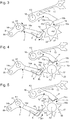
- the pusher is actuated by passing from a rest position to an activation position in order to act on the corrector 2 and thus cause its displacement in the first direction S1 about the axis of rotation A1. .
- the elastic member 3 constituting its flexible end, then comes into contact with a tooth 17 of the toothed wheel 11 in order to transmit to the latter this movement in the optical drive to drive in a movement of rotation about an axis of rotation A2. More specifically, with reference to the figure 3 during this transmission of displacement, the elastic member 3 thus being in contact with this tooth 17, is deformed in a first direction P1 until the difference between the bearing zone 5 and the second zone contact 4b is zero.
- the elastic member 3 is deformed until this second contact zone 4b abuts on the bearing zone 5 of the rigid portion 6 of the first portion 14a of the corrector 2. It will be noted that in this mechanism 1, the torque applied by the elastic member 3 to the toothed wheel 11 is smaller than the holding torque applied to the toothed wheel 11 by the jumper 12.
- the jumper 12 which is in contact with the teeth 17 of this wheel 11, also performs a rotational movement about the axis of rotation A3 by generating a deformation of the spring jumper 13 and this, until its tip P is positioned on the other side of the top 20 of the tooth 17 of the toothed wheel 11 defining the first recess 16a where was initially located this jumper 12 d ' a second recess 16b consecutive wheel 11 in which this jumper 12 is then disposed and finalizes the corrected function that is to say, locks the toothed wheel 11 in a final indexed position of correction.
- the final stop position of the corrector 2 makes it possible to bring this tooth 17 between these first and second recesses 16a, 16b, and in particular its top 20, onto the second slope 15b of the jumper.
- the stroke of the corrector 2 is specifically defined to ensure a displacement of the toothed wheel 11 so as to cause the passage of the free end of the jumper 12 of the first recess 16a to the second recess 16b.
- the elastic member 3 expands so as to cover its initial shape.
- This method then comprises a step of configuring the correction mechanism 1 in a rest phase.
- the pusher is then arranged in its rest position by being released by the user of the timepiece 200.
- the corrector 2 then returns to its initial position under the action of a restoring force exerted on the latter by the corrector spring which is adapted to cause it in a displacement in the second direction S2 about the axis of rotation A1.
- This second sense S2 is contrary to the first sense S1.
- This displacement of the corrector 2 has no effect on the indexed position of correction of the toothed wheel 11.
- the elastic member 3 comes into contact at its first contact zone 4a with a tooth 17 of the toothed wheel 11 and then deforms in a second direction P2 opposite the first direction P1 and without causing the toothed wheel 11 in a displacement around the axis of rotation A2.
- the torque applied by the elastic member 3 to the toothed wheel 11 is less than the holding torque applied to the toothed wheel 11 by the jumper 12.
- the figure 5 illustrates a maximum deformation of this elastic member 3 when the latter is in contact with an apex 20 of the tooth 17. It will be noted that during this deformation, the difference between the bearing zone 5 and the second contact zone 4b decreases but never becomes zero.
- the elastic member 3 is deformed without the second contact zone 4b abutting the bearing zone 5 of the rigid portion 6 of the first portion 14a of the corrector 2.
- this elastic member 3 is able to deform in the first and second deformation directions P1, P2 which are substantially parallel or parallel to the first and second directions of displacement S1, S2 of the corrector 2.
- the corrector 2 bears on the initial stop which defines the end of the race of the corrector 2 and this when it is configured in its initial position.
- the invention makes it possible to simplify the implementation of a correction of a function of a movement 201 of a timepiece 200, in particular by increasing the maximum correction stroke in comparison with that of the correctors of the state of the technique while improving its robustness and without requiring the addition of an additional piece such as an attached removable finger.
- a mechanism 1 does not generate congestion additional in the box of the timepiece 200 and be easily arranged in existing movements.
Priority Applications (4)
| Application Number | Priority Date | Filing Date | Title |
|---|---|---|---|
| EP17203880.4A EP3489766A1 (de) | 2017-11-27 | 2017-11-27 | Mechanismus zur korrektur einer bewegungsfunktion einer uhr |
| US16/162,534 US11287023B2 (en) | 2017-11-27 | 2018-10-17 | Correction mechanism for a function of a movement of a timepiece |
| JP2018204828A JP6666979B2 (ja) | 2017-11-27 | 2018-10-31 | 時計ムーブメントの機能のための修正機構 |
| CN201811366573.0A CN109839814B (zh) | 2017-11-27 | 2018-11-16 | 用于钟表机芯的功能的校正机构 |
Applications Claiming Priority (1)
| Application Number | Priority Date | Filing Date | Title |
|---|---|---|---|
| EP17203880.4A EP3489766A1 (de) | 2017-11-27 | 2017-11-27 | Mechanismus zur korrektur einer bewegungsfunktion einer uhr |
Publications (1)
| Publication Number | Publication Date |
|---|---|
| EP3489766A1 true EP3489766A1 (de) | 2019-05-29 |
Family
ID=60473441
Family Applications (1)
| Application Number | Title | Priority Date | Filing Date |
|---|---|---|---|
| EP17203880.4A Pending EP3489766A1 (de) | 2017-11-27 | 2017-11-27 | Mechanismus zur korrektur einer bewegungsfunktion einer uhr |
Country Status (4)
| Country | Link |
|---|---|
| US (1) | US11287023B2 (de) |
| EP (1) | EP3489766A1 (de) |
| JP (1) | JP6666979B2 (de) |
| CN (1) | CN109839814B (de) |
Cited By (2)
| Publication number | Priority date | Publication date | Assignee | Title |
|---|---|---|---|---|
| EP4194965A1 (de) | 2021-12-08 | 2023-06-14 | Patek Philippe SA Genève | Betätigungsmechanismus für uhr |
| EP4246247A1 (de) | 2022-03-14 | 2023-09-20 | Patek Philippe SA Genève | Betätigungsmechanismus für uhr |
Families Citing this family (1)
| Publication number | Priority date | Publication date | Assignee | Title |
|---|---|---|---|---|
| EP3605243A1 (de) | 2018-07-31 | 2020-02-05 | Montres Breguet S.A. | Uhr-anzeigemechanismus mit variabler geometrie und elastischem zeiger |
Citations (5)
| Publication number | Priority date | Publication date | Assignee | Title |
|---|---|---|---|---|
| EP2159652A1 (de) * | 2008-08-26 | 2010-03-03 | Agenhor SA | Anzeigemechanismus für Uhr, der die Anzeige sowie das Ausblenden der aktuellen Uhrzeit ermöglicht |
| EP2672335A1 (de) * | 2012-06-04 | 2013-12-11 | ETA SA Manufacture Horlogère Suisse | Flexibles Zahnrad |
| CH708741A2 (fr) | 2013-10-25 | 2015-04-30 | Manuf La Joux Perret Sa | Dispositif correcteur pour pièce d'horlogerie. |
| EP2950164A1 (de) * | 2014-05-28 | 2015-12-02 | Omega SA | Schnellkorrektursystem einer Stundeninformation oder anderen Information |
| EP3435169A1 (de) | 2017-07-25 | 2019-01-30 | Blancpain SA | Arretiermechanismus für schlagwerkmechanismus einer uhr |
Family Cites Families (12)
| Publication number | Priority date | Publication date | Assignee | Title |
|---|---|---|---|---|
| US2717488A (en) * | 1952-01-07 | 1955-09-13 | Gen Horlogere | Noiseless anchor-escapement, particularly for clock-works |
| CH607557GA3 (de) * | 1974-11-06 | 1978-08-31 | Bulova Watch Co Inc | Uhrenkalendereinrichtung. |
| JPS554552A (en) * | 1978-06-27 | 1980-01-14 | Seiko Instr & Electronics Ltd | Date feed mechanism of watch |
| US4240249A (en) * | 1979-03-05 | 1980-12-23 | Kruglov Gennady A | Instantaneous calendar device for timepieces |
| CH664863GA3 (de) * | 1986-04-09 | 1988-04-15 | ||
| EP1293849A1 (de) * | 2001-09-12 | 2003-03-19 | Groupe S.F.T. SA | Zeigerstellungsmechanismus für eine Uhr |
| EP1555584A1 (de) * | 2004-01-13 | 2005-07-20 | Rolex S.A. | Gezähntes Drehteil für die Einholung des Spiels, Getriebe, und die Benutzung dieses Getriebes |
| DE602006016553D1 (de) * | 2006-03-30 | 2010-10-14 | Richemont Int Sa | Umkehrbare Uhr |
| EP2413202B1 (de) * | 2010-07-30 | 2017-11-15 | ETA SA Manufacture Horlogère Suisse | Verfahren zur Verbesserung der Verschleiss- und Stossfestigkeit einer Uhrwerkskomponente. Verschleiß- und stoßfester Anker für Uhrwerk |
| EP2642354B1 (de) * | 2012-03-23 | 2015-10-21 | Omega SA | Anzeige- und Korrekturmechanismus des Zustands von mindestens zwei verschiedenen zeitlichen Größen |
| EP2824521A3 (de) * | 2013-07-12 | 2016-06-01 | Rolex Sa | Uhrmechanismus, Uhrwerk und Uhr |
| EP3208666B1 (de) * | 2016-02-19 | 2018-11-21 | Blancpain SA | Uhrenrad mit spielnachstellung |
-
2017
- 2017-11-27 EP EP17203880.4A patent/EP3489766A1/de active Pending
-
2018
- 2018-10-17 US US16/162,534 patent/US11287023B2/en active Active
- 2018-10-31 JP JP2018204828A patent/JP6666979B2/ja active Active
- 2018-11-16 CN CN201811366573.0A patent/CN109839814B/zh active Active
Patent Citations (5)
| Publication number | Priority date | Publication date | Assignee | Title |
|---|---|---|---|---|
| EP2159652A1 (de) * | 2008-08-26 | 2010-03-03 | Agenhor SA | Anzeigemechanismus für Uhr, der die Anzeige sowie das Ausblenden der aktuellen Uhrzeit ermöglicht |
| EP2672335A1 (de) * | 2012-06-04 | 2013-12-11 | ETA SA Manufacture Horlogère Suisse | Flexibles Zahnrad |
| CH708741A2 (fr) | 2013-10-25 | 2015-04-30 | Manuf La Joux Perret Sa | Dispositif correcteur pour pièce d'horlogerie. |
| EP2950164A1 (de) * | 2014-05-28 | 2015-12-02 | Omega SA | Schnellkorrektursystem einer Stundeninformation oder anderen Information |
| EP3435169A1 (de) | 2017-07-25 | 2019-01-30 | Blancpain SA | Arretiermechanismus für schlagwerkmechanismus einer uhr |
Cited By (2)
| Publication number | Priority date | Publication date | Assignee | Title |
|---|---|---|---|---|
| EP4194965A1 (de) | 2021-12-08 | 2023-06-14 | Patek Philippe SA Genève | Betätigungsmechanismus für uhr |
| EP4246247A1 (de) | 2022-03-14 | 2023-09-20 | Patek Philippe SA Genève | Betätigungsmechanismus für uhr |
Also Published As
| Publication number | Publication date |
|---|---|
| US20190162288A1 (en) | 2019-05-30 |
| US11287023B2 (en) | 2022-03-29 |
| JP2019095435A (ja) | 2019-06-20 |
| CN109839814A (zh) | 2019-06-04 |
| JP6666979B2 (ja) | 2020-03-18 |
| CN109839814B (zh) | 2021-05-04 |
Similar Documents
| Publication | Publication Date | Title |
|---|---|---|
| EP2977829B1 (de) | Anordnung mit beweglichem Bremselement einer Uhr | |
| EP2701014A1 (de) | Kupplungswippe und Kupplungsvorrichtung für Uhrmechanismus | |
| EP3483663B1 (de) | Antriebsvorrichtung für kalendersystem einer uhr | |
| EP3144743B1 (de) | Uhrwerk mit einem datumskorrektur-mechanismus | |
| EP3489766A1 (de) | Mechanismus zur korrektur einer bewegungsfunktion einer uhr | |
| EP2784603B1 (de) | Vorrichtung zur Anzeige einer Zeitinformation | |
| EP1152303A1 (de) | Uhr mit Aufzugsmechanismus und mit Korrekturmechanismus für mindestens zwei anzeigende Organe | |
| EP2798413B1 (de) | Feder für uhrwerk | |
| EP3220206B1 (de) | Übertragungsvorrichtung für uhr | |
| EP2884345B1 (de) | Hebelfeder für uhrwerk | |
| CH714372A2 (fr) | Mécanisme de correction d'une fonction d'un mouvement d'une pièce d'horlogerie. | |
| EP3246763B1 (de) | Schnellkorrekturmechanismus für uhr | |
| EP2798414B1 (de) | Feder für uhrwerk | |
| CH712477A2 (fr) | Dispositif de correction rapide d'une indication fournie par un mécanisme d'affichage pour pièce d'horlogerie. | |
| CH716423B1 (fr) | Ensemble limiteur d'horlogerie pour une montre comportant au moins un tourbillon ou un carrousel. | |
| CH712225B1 (fr) | Dispositif régulateur comportant un organe de correction d'anisochronisme. | |
| CH708741A2 (fr) | Dispositif correcteur pour pièce d'horlogerie. | |
| EP3770695B1 (de) | Anschlagkäfig für uhr mit käfiganschlagblatt | |
| EP3770694B1 (de) | Anschlagkäfig für uhr mit zwei elastischen anschlagelementen | |
| EP3770693B1 (de) | Anschlagmechanismus für uhrenkäfig mit anschlagrad | |
| EP2600214B1 (de) | Übertragungsmechanismus zwischen zwei Teilen eines Schaltgestänges für ein Uhrwerk | |
| EP4312083A1 (de) | Kupplungs-ausrückvorrichtung für uhr | |
| CH716774B1 (fr) | Dispositif horloger de couplage et d'indexation. | |
| CH716422B1 (fr) | Ensemble limiteur d'horlogerie pour une montre comportant au moins un tourbillon ou un carrousel. | |
| CH714615A2 (fr) | Mécanisme de transmission d'une force d'armage, mouvement et pièce d'horlogerie mécanique. |
Legal Events
| Date | Code | Title | Description |
|---|---|---|---|
| PUAI | Public reference made under article 153(3) epc to a published international application that has entered the european phase |
Free format text: ORIGINAL CODE: 0009012 |
|
| STAA | Information on the status of an ep patent application or granted ep patent |
Free format text: STATUS: THE APPLICATION HAS BEEN PUBLISHED |
|
| AK | Designated contracting states |
Kind code of ref document: A1 Designated state(s): AL AT BE BG CH CY CZ DE DK EE ES FI FR GB GR HR HU IE IS IT LI LT LU LV MC MK MT NL NO PL PT RO RS SE SI SK SM TR |
|
| AX | Request for extension of the european patent |
Extension state: BA ME |
|
| STAA | Information on the status of an ep patent application or granted ep patent |
Free format text: STATUS: REQUEST FOR EXAMINATION WAS MADE |
|
| 17P | Request for examination filed |
Effective date: 20191129 |
|
| RBV | Designated contracting states (corrected) |
Designated state(s): AL AT BE BG CH CY CZ DE DK EE ES FI FR GB GR HR HU IE IS IT LI LT LU LV MC MK MT NL NO PL PT RO RS SE SI SK SM TR |
|
| STAA | Information on the status of an ep patent application or granted ep patent |
Free format text: STATUS: EXAMINATION IS IN PROGRESS |
|
| STAA | Information on the status of an ep patent application or granted ep patent |
Free format text: STATUS: EXAMINATION IS IN PROGRESS |
|
| 17Q | First examination report despatched |
Effective date: 20211112 |
|
| TPAC | Observations filed by third parties |
Free format text: ORIGINAL CODE: EPIDOSNTIPA |
|
| P01 | Opt-out of the competence of the unified patent court (upc) registered |
Effective date: 20230611 |