EP3705949B1 - Drehmomentbegrenzungsmechanismus eines uhrwerks - Google Patents
Drehmomentbegrenzungsmechanismus eines uhrwerks Download PDFInfo
- Publication number
- EP3705949B1 EP3705949B1 EP19160841.3A EP19160841A EP3705949B1 EP 3705949 B1 EP3705949 B1 EP 3705949B1 EP 19160841 A EP19160841 A EP 19160841A EP 3705949 B1 EP3705949 B1 EP 3705949B1
- Authority
- EP
- European Patent Office
- Prior art keywords
- wheel
- arm
- rotation
- mobile
- relative
- Prior art date
- Legal status (The legal status is an assumption and is not a legal conclusion. Google has not performed a legal analysis and makes no representation as to the accuracy of the status listed.)
- Active
Links
Images


Classifications
-
- G—PHYSICS
- G04—HOROLOGY
- G04B—MECHANICALLY-DRIVEN CLOCKS OR WATCHES; MECHANICAL PARTS OF CLOCKS OR WATCHES IN GENERAL; TIME PIECES USING THE POSITION OF THE SUN, MOON OR STARS
- G04B11/00—Click devices; Stop clicks; Clutches
- G04B11/001—Clutch mechanism between two rotating members with transfer of movement in both directions, possibly with limitation on the transfer of power
- G04B11/003—Clutch mechanism between two rotating members with transfer of movement in both directions, possibly with limitation on the transfer of power with friction member, e.g. with spring action
-
- G—PHYSICS
- G04—HOROLOGY
- G04B—MECHANICALLY-DRIVEN CLOCKS OR WATCHES; MECHANICAL PARTS OF CLOCKS OR WATCHES IN GENERAL; TIME PIECES USING THE POSITION OF THE SUN, MOON OR STARS
- G04B13/00—Gearwork
- G04B13/005—Gearwork where a revolution in both directions is changed into a revolution in one direction
-
- G—PHYSICS
- G04—HOROLOGY
- G04B—MECHANICALLY-DRIVEN CLOCKS OR WATCHES; MECHANICAL PARTS OF CLOCKS OR WATCHES IN GENERAL; TIME PIECES USING THE POSITION OF THE SUN, MOON OR STARS
- G04B13/00—Gearwork
- G04B13/02—Wheels; Pinions; Spindles; Pivots
- G04B13/021—Wheels; Pinions; Spindles; Pivots elastic fitting with a spindle, axis or shaft
- G04B13/023—Wheels; Pinions; Spindles; Pivots elastic fitting with a spindle, axis or shaft allowing rotational slipping when a threshold torque is exceeded
-
- G—PHYSICS
- G04—HOROLOGY
- G04B—MECHANICALLY-DRIVEN CLOCKS OR WATCHES; MECHANICAL PARTS OF CLOCKS OR WATCHES IN GENERAL; TIME PIECES USING THE POSITION OF THE SUN, MOON OR STARS
- G04B3/00—Normal winding of clockworks by hand or mechanically; Winding up several mainsprings or driving weights simultaneously
- G04B3/06—Keys or the like with means preventing overwinding
-
- G—PHYSICS
- G04—HOROLOGY
- G04B—MECHANICALLY-DRIVEN CLOCKS OR WATCHES; MECHANICAL PARTS OF CLOCKS OR WATCHES IN GENERAL; TIME PIECES USING THE POSITION OF THE SUN, MOON OR STARS
- G04B3/00—Normal winding of clockworks by hand or mechanically; Winding up several mainsprings or driving weights simultaneously
- G04B3/08—Normal winding of clockworks by hand or mechanically; Winding up several mainsprings or driving weights simultaneously by parts of the cases
- G04B3/10—Protecting means preventing overwinding
Definitions
- the invention relates to an internal torque limiter mechanism for a watch movement, said torque limiter mechanism comprising a first mobile comprising a first felloe and arranged to pivot about a first axis of rotation relative to a structure or a plate or a bridge, said first mobile comprising at least one first elastic arm which, in the free state of said first mobile, projects in the direction of said first axis of rotation relative to said first felloe, and at least one second mobile comprising a second felloe and arranged to pivot relative to said structure about a second axis of rotation parallel to or coincident with said first axis of rotation in at least partial overlap with said first mobile.
- the invention also relates to a barrel winding device comprising a control member arranged to be operated by a user and to drive an input pinion meshing with said first mobile or said second mobile of such a torque limiting mechanism, which said device comprises.
- the invention also relates to a clockwork movement comprising, between an input mechanism and an output mechanism, such a torque limiting mechanism.
- the invention also relates to a timepiece, in particular a watch, comprising at least one such torque limiting mechanism, and/or at least one such movement.
- the invention relates to the field of watch mechanisms, and more particularly to the protection of certain mechanisms against excessive torque input, in particular energy recharging mechanisms such as winding mechanisms, or correction and/or display mechanisms, in particular calendar mechanisms or the like.
- Some watch mechanisms are designed to store and restore significant quantities of energy, however their dimensioning is limited by that of the case of the timepiece concerned, and it is not possible to apply high safety coefficients to them to protect them against excessive torque applied to them.
- the significant bulk of the mechanisms Known torque limiters restrict the integration of complications into the timepiece.
- the user does not have the possibility of knowing whether he has correctly and safely carried out a complete manipulation, in particular for winding a mechanism.
- the document CH703483A2 on behalf of SEIKO discloses a wheel with a torque limiting mechanism comprising an engagement arm portion extending from a proximal end portion to a distal end portion equipped with an engagement projection, which is elastically engaged in a pressure-engaged portion.
- the projection is detached from the engaged portion to rotate the crown wheels when a torque exceeding a threshold value is exerted.
- a force directed from the proximal end portion to the distal end portion is applied to the projection when a manual winding torque is applied to the mechanism and adapted to separate the projection from the engaged portion.
- the invention proposes to produce a torque limiting device which is very compact, economical and whose use allows the user to easily determine whether a maneuver has been carried out correctly.
- the invention relates to an internal torque limiting mechanism for a clock movement, according to claim 1
- the invention also relates to a barrel arming device comprising such a torque limiting mechanism.
- the invention also relates to a clockwork movement comprising, between an input mechanism and an output mechanism, such a torque limiting mechanism.
- the invention also relates to a timepiece, in particular a watch, comprising at least one such torque limiting mechanism, and/or at least one such movement.
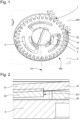
- the invention relates to a torque limiter mechanism 100 for a watch.
- This mechanism 100 comprises a first mobile 1, which comprises a first rim 10 and is arranged to pivot about a first axis of rotation D1 relative to a structure 4 or a plate or a bridge.
- This first mobile 1 comprises at least one first elastic arm 31, which, in the free state of the first mobile 1, projects in the direction of the first axis of rotation D1 relative to the first felloe 10. More particularly and non-limitingly, this first elastic arm 31 is movable in a first cutout 41 of the first mobile 1.
- the mechanism 100 comprises at least one second mobile 2, which comprises a second rim 20 and arranged to pivot relative to the structure 4 around a second axis of rotation D2, parallel or coincident with the first axis of rotation D1, at least partially overlapping the first.
- the mechanism 100 comprises a travel limiter 5, which is fixed to the structure 4, and which is arranged to hold the second mobile 2 on the first mobile 1 for their cooperation in friction support in certain relative angular positions.
- the invention is here more particularly described in the simplified case where the mechanism 100 only comprises the first mobile 1 and the second mobile 2, the person skilled in the art will be able to extrapolate this to a greater number of mobiles, for a mechanism comprising more than one input and one output.
- the invention proposes to vary the friction force between the first mobile 1 and the second mobile 2.
- the second mobile 2 and/or the travel limiter 5 and/or the structure 4 comprises at least one relief forming a ramp, and which projects in a direction parallel to or coincident with that of the first axis of rotation D1.
- This relief is arranged to, in certain relative angular positions of the component carrying this relief relative to the first mobile 1, cooperate in frictional support with at least one first elastic arm 31 of said first mobile 1, and, in other relative angular positions, allow a relative travel without friction between the first mobile 1 and the component carrying this relief.
- the mechanism constitutes a simple ratchet, arranged to vary the axial position of the first elastic arm of the first mobile 1, or to vary the axial position of the entire first mobile 1 and thus vary the friction force applied to the second mobile 2.
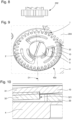
- the invention relates more particularly to the case where the second mobile 2 comprises at least one second arm 32 forming a ramp and which, in the free state of the second mobile 2, projects in the direction of the second axis of rotation D2 relative to the second rim 20.
- this second arm 32 is a second elastic arm 32. More particularly still, this second arm 32 is a second elastic arm 32 movable in a second cutout 42.
- first mobile 1 and the second mobile 2 When only the first mobile 1 and the second mobile 2 have reliefs projecting relative to their respective rim, they are mounted head to tail, with each first elastic arm 31 projecting towards the second mobile 2, and with each second arm 32 projecting towards the first mobile 1.
- the second axis of rotation D2 is distant from the first axis of rotation D1.
- the second axis of rotation D2 is merged with the first axis of rotation D1.
- each second arm 32 is arranged to cooperate successively, during a relative rotation of the second mobile 2 with respect to the first mobile 1, cyclically with the first serge 10, a first elastic arm 31, and a first cutout 41 before returning in cooperation with the first serge 10.
- first mobile 1 and the second mobile 2 are arranged, if they are coaxial, to rotate in the same direction: either they both rotate in the same direction, or one rotates and the other is blocked. These mobiles can, in other applications where they are not coaxial, rotate in opposite directions to each other.
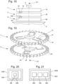
- Each first elastic arm 31 of the first mobile defines a first ramp, which begins at a joint 310 with the first felloe 10, and rises to a first peak. More particularly and as visible in the figures, this first elastic arm 31 is a cantilever arm, and the peak coincides with the distal end of this first arm 31, the edge of which defines a first front surface 311.
- any relief of an opposing mobile, in particular the second mobile 2 during a rotation always in the same direction of each mobile, climbs this first ramp, then falls after passing the peak; depending on the configuration, this relief falls on the first felloe 10, or in the first cutout 41. This jump corresponds to the disengagement of the mechanism.
- the first elastic arm 31 comprises an ascending ramp from the first felloe 10 to the first apex, then a descending ramp from the first apex to the first felloe 10.
- the relief of the second mobile 2 can be formed in different ways, the figures represent this relief in the form of a second elastic arm 32 similar to the first elastic arm 31 of the first mobile 1, this configuration is advantageous because it makes it possible to use, for the first mobile 1 and the second mobile 2, identical components, at least at the level of these reliefs cooperating with each other; of course, depending on the application, the first mobile 1 and the second mobile 2 can comprise different teeth, depending on the components of the movement with which they cooperate.
- each first elastic arm 31 is arranged to cooperate successively, during a relative rotation of the second mobile 2 relative to the first mobile 1, with the second felloe 20, a second arm 32, and a second cutout 42 which comprises the second mobile 2, before returning in cooperation with the second serge 20.
- the arrangement with a first front surface 311, and a second similar front surface 312 for the second elastic arm allows, in a particular direction of rotation, the cooperation in abutment of one with the other, and the driving in rotation by simple support, without friction, of one mobile by the other, whereas, in the opposite direction of rotation, the elastic arms cooperate progressively until a release position where one of the mobiles is no longer driven by the other.
- each first elastic arm 31 is a substantially annular sector which extends substantially concentrically relative to the first axis of rotation D1. Its radial section may be constant, or progressive or degressive, so as to obtain variable friction according to the relative angle between the opposing mobiles.
- the upper surface of the first elastic arm 31 extends, radially relative to the first axis of rotation D1, perpendicular thereto. In a variant not illustrated, this first elastic arm 31 may also be warped and sloping.
- Each second elastic arm 32 may be formed in a similar manner. And in particular, more particularly, each second elastic arm 32 extends substantially concentrically relative to the second axis of rotation D2.
- At least one first elastic arm 31 and/or at least one second arm 32 extends substantially radially relative to the axis of rotation of the mobile which carries it.
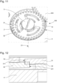
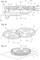
- the mechanism 100 comprises, in at least partial superposition in a direction parallel to the axis of rotation of each of them, more than two mobiles arranged to cooperate two by two in friction support, and all mounted captive between the structure 4 and the travel limiter 5, and at least one intermediate mobile between the end mobiles comprises at least one elastic arm projecting on each side of its rim, in its axial direction: this is the case of the second mobile 2 of the figure 18 , which cooperates, on the upper side of the second rim 20, with the first mobile 1, and, on the lower side of the second rim 20, with the relief 39 projecting from the third rim 90 of a third mobile 9 resting on the structure 4.
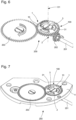
- the invention also relates to a barrel winding device 200, comprising a control member 201 which is arranged to be operated by a user, such as a control rod, a pusher, a target, a bezel, or the like, and to drive an input pinion 202 meshing with the first mobile 1 or the second mobile 2 of such a torque limiter mechanism 100, which this device 200 comprises.
- the other mobile of this mechanism 100, the second mobile 2 or respectively the first mobile 1 is arranged to drive a ratchet 203 of a motor or striking barrel, the whole being assembled on the structure 4 which is, in this particular case, a barrel bridge.
- the travel limiter 5 is advantageously a screw fixed on this structure, which facilitates the assembly of the entire mechanism 100 and allows disassembly.
- the usual crown wheel is split into two boards, constituting the first mobile 1 and the second mobile 2, and advantageously in a very economical embodiment, first 31 and second 32 elastic arms are cut and folded in each of them. These boards are then mounted head to tail in place of the crown wheel.
- the first mobile 1 meshes with a winding pinion 202
- the second mobile 2 meshes with the barrel ratchet 203.
- the first mobile 1 and the second mobile 2 are secured by means of the elastic arms 31 and 32, which transmit a torque by friction. If the torque applied to the winding pinion 202 is too great, the elastic arms 31 and 32 deform and slide against each other, until the system disengages. When disengaging, the jump made by the elastic arms 31 and 32 during the unlatching produces a characteristic noise which informs the user that the barrel is fully reloaded.
- each mobile 1, 2 has three elastic arms 31, 32. After disengagement, the first mobile 1 makes a third of a turn.
- the clearance between the rims of the two mobiles is between 0.06 and 0.10 mm, and the axial elastic travel of each arm is half the value of this clearance.
- the invention also relates to a clockwork movement 500 comprising, between an input mechanism 300 and an output mechanism 400, such a torque limiter mechanism 100.
- the input mechanism 300 is a calendar or date mechanism
- the output mechanism 400 is a month, or day of the week, or date display mechanism.
- the torque limiter 100 is arranged to control, during any jump of an arm of a mobile 1 or 2 of the torque limiter 100, the advancement of one step of the display concerned.
- the control of the correction of the day of the week display is a cyclic control for which the device according to the invention is well suited. In the same way, a clear adjustment of date correction can be obtained.
- the invention is easily adaptable to any semi-instantaneous or trailing display: months, days, time zones, hours, or others.
- the invention also makes it possible to produce an inverter for mono- or bidirectional winding: the first mobile 1 meshes with an automatic winding oscillating weight, and the second mobile 2 meshes with the winding gear train.
- the system clicks and the second mobile 2 does not rotate.
- the first mobile 1 rotates in the counterclockwise direction, it drives the second mobile 2 through the distal ends 311, 321, of the elastic arms 31 and 32.
- the movement 500 comprises an automatic winding oscillating weight and an automatic winding gear train
- a torque limiter 100 comprising elastic arms 31, 32, constitutes an inverter for mono- or bidirectional winding, the first mobile 1 meshing with the automatic winding oscillating weight, and the second mobile 2 meshing with the winding gear train, such that, when the first mobile 1 rotates in the clockwise direction, or respectively counterclockwise, the system unlatches and the second mobile 2 does not rotate, and when the first mobile 1 rotates in the counterclockwise direction, or respectively clockwise, it drives the second mobile 2 through distal ends 311, 321, which the arms respectively comprise elastics 31, 32.
- the invention also makes it possible to produce a blocker, for example to prevent a barrel from discharging.
- the ratchet can be arranged with elastic arms, and the barrel bridge with notches, so that the ends of the arms fall into the notches.
- the movement 500 comprises at least one barrel and one ratchet arranged on a barrel bridge, and such a torque limiter 100 constitutes a blocker, to prevent a barrel from discharging, the ratchet constituting one of the mobiles 1, 2, and comprising arms elastic, and the barrel bridge constituting a structure 4 and comprising notches, so that the ends of the arms fall into the notches.
- the input mechanism 300 is a minute repeater trigger mechanism
- the output mechanism 400 is a minute repeater mechanism.
- the torque limiter 100 is then arranged to control, during any jump of an arm of a mobile 1 or 2 of the torque limiter 100, the tilting of an isolator, which the minute repeater mechanism comprises, to prohibit the control of another repeater during the execution of a repeater strike.
- the invention also relates to a timepiece 1000 comprising at least one such torque limiter mechanism 100, and/or at least one such movement 500. More particularly, this timepiece 1000 is a watch.
- the proposed mechanism is very simple, because it does not require any elastic return means other than those carried by the first mobile 1, and preferably the second mobile 2.
- the coaxial arrangement of the mobiles is particularly advantageous, because the forces exerted on the mobiles are symmetrical, and the transmissible force is maximum.
- the arrangement in the clockwork movement involves offsetting the first 1 and the second 2 mobiles, it is advantageous to increase the number of elastic arms to avoid blind spots.
- the production of mobiles can come, very economically, from stamping, the mobiles can be identical, and possibly differ only by their teeth.
- the invention allows the user to ensure the proper completion of the function he is performing, winding, display correction, triggering, and ensures the protection of the components of the mechanism concerned against any excessive torque. For example, the user can wind a barrel fully without fear of breaking a component.
Landscapes
- Physics & Mathematics (AREA)
- General Physics & Mathematics (AREA)
- Transmission Devices (AREA)
- Electromechanical Clocks (AREA)
- Motorcycle And Bicycle Frame (AREA)
- Braking Arrangements (AREA)
Claims (21)
- Interner Drehmomentbegrenzungsmechanismus (100) für ein Uhrwerk (500), wobei der Drehmomentbegrenzungsmechanismus (100) beinhaltet:einen ersten Drehteil (1), der einen ersten Fusskreis (10) beinhaltet und angeordnet ist, um sich in Bezug auf eine Struktur (4) um eine erste Drehachse (D1) herum zu drehen, wobei der erste Drehteil (1) mindestens einen ersten elastischen Arm (31) beinhaltet, der im freien Zustand des ersten Drehteils (1) in die Richtung der ersten Drehachse (D1) in Bezug auf den ersten Fusskreis (10) hervorstehend ist, undmindestens einen zweiten Drehteil (2), der einen zweiten Fusskreis (20) beinhaltet und angeordnet ist, um sich in Bezug auf die Struktur (4) um eine zweite Drehachse (D2), die parallel zur ersten Drehachse (D1) ist, oder mit dieser zusammenfällt, in mindestens teilweiser Überlappung mit dem ersten Drehteil (1) herum zu drehen, wobei der zweite Drehteil (2) mindestens einen zweiten Arm (32) beinhaltet, der angeordnet ist, um in Reibanlage mit dem ersten Drehteil (1) zu deren Antrieb in Bezug zueinander zusammenzuwirken, wobei der mindestens eine zweite Arm (32) eine Rampe bildet, im freien Zustand des zweiten Drehteils (2) in der Richtung der zweiten Drehachse (D2) in Bezug zum zweiten Fusskreis (20) hervorstehend ist,einen Wegbegrenzer (5), der an der Struktur (4) fixiert ist, und der angeordnet ist, um den zweiten Drehteil (2) auf dem ersten Drehteil (1) zu deren Zusammenwirken in Reibanlage in bestimmten relativen Winkelpositionen zueinander zu halten,wobei der zweite Arm (32) angeordnet ist, um in bestimmten relativen Winkelpositionen in Bezug auf den ersten Drehteil (1) in Reibanlage mit mindestens einem ersten elastischen Arm (31) des ersten Drehteils (1) zusammenzuwirken, und in anderen relativen Winkelpositionen einen relativen Weg ohne Reibung zwischen dem ersten Drehteil (1) und dem zweiten Drehteil (2) zu erlauben.
- Mechanismus (100) nach Anspruch 1, dadurch gekennzeichnet, dass mindestens ein erster elastischer Arm (31) in einem ersten Ausschnitt (41) des ersten Fusskreises (10) beweglich ist.
- Mechanismus (100) nach einem der Ansprüche 1 bis 2, dadurch gekennzeichnet, dass der zweite Arm (32) ein zweiter elastischer Arm (32) ist.
- Mechanismus (100) nach Anspruch 3, dadurch gekennzeichnet, dass mindestens der zweite Arm (32) in einem zweiten Ausschnitt (42) des zweiten Fusskreises (20) beweglich ist.
- Mechanismus (100) nach Anspruch 3 oder 4, dadurch gekennzeichnet, dass der erste Drehteil (1) und der zweite Drehteil (2) entgegengerichtet montiert sind, wobei jeder erste elastische Arm (31) zum zweiten Drehteil (2) hervorsteht, und wobei jeder zweite Arm (32) zum ersten Drehteil (1) hervorsteht.
- Mechanismus (100) nach einem der Ansprüche 1 bis 5, dadurch gekennzeichnet, dass die zweite Drehachse (D2) von der ersten Drehachse (D1) beabstandet ist.
- Mechanismus (100) nach einem der Ansprüche 1 bis 5, dadurch gekennzeichnet, dass die zweite Drehachse (D2) mit der ersten Drehachse (D1) zusammenfallend ist.
- Mechanismus (100) nach Anspruch 3 oder 4, und nach einem der Ansprüche 1 bis 7, dadurch gekennzeichnet, dass jeder zweite Arm (32) angeordnet ist, um nacheinander bei einer relativen Drehung des zweiten Drehteils (2) in Bezug zum ersten Drehteil (1) mit dem ersten Fusskreis (10), einem ersten elastischen Arm (31) und einem ersten Ausschnitt (41) zusammenzuwirken, bevor er in Zusammenwirkung mit dem ersten Fusskreis (10) zurückkehrt.
- Mechanismus (100) nach Anspruch 3 oder 4, und nach einem der Ansprüche 1 bis 8, dadurch gekennzeichnet, dass jeder erste elastische Arm (31) angeordnet ist, um nacheinander bei einer relativen Drehung des zweiten Drehteils (2) in Bezug zum ersten Drehteil (1) mit dem zweiten Fusskreis (20), einem zweiten elastischen Arm (32) und einem zweiten Ausschnitt (42) zusammenzuwirken, den der zweite Drehteil (2) beinhaltet, bevor er in Zusammenwirkung mit dem zweiten Fusskreis (20) zurückkehrt.
- Mechanismus (100) nach einem der Ansprüche 1 bis 9, dadurch gekennzeichnet, dass jeder erste elastische Arm (31) ein Kreissektor ist, der sich im Wesentlichen konzentrisch in Bezug zur ersten Drehachse (D1) erstreckt.
- Mechanismus (100) nach Anspruch 3 oder 4, und nach einem der Ansprüche 1 bis 10, dadurch gekennzeichnet, dass sich jeder zweite Arm (32) im Wesentlichen konzentrisch in Bezug zur zweiten Drehachse (D2) erstreckt.
- Mechanismus (100) nach Anspruch 3 oder 4, und nach einem der Ansprüche 1 bis 8, dadurch gekennzeichnet, dass sich mindestens ein erster elastischer Arm (31) und/oder mindestens ein zweiter Arm (32) im Wesentlichen radial in Bezug zur Drehachse des Drehteils, den sie trägt, erstreckt.
- Mechanismus (100) nach einem der Ansprüche 1 bis 12, dadurch gekennzeichnet, dass der Mechanismus (100) zumindest in teilweiser Überlagerung in einer Richtung parallel zur Drehachse eines jeden von ihnen mehr als zwei Drehteile beinhaltet, die angeordnet sind, um paarweise in Reibanlage zusammenzuwirken, und allesamt zwischen der Struktur (4) und dem Wegbegrenzer (5) eingeschlossen montiert sind, und dadurch, dass mindestens ein Zwischendrehteil zwischen den Enddrehteilen mindestens einen auf jeder Seite seines Fusskreises in der axialen Richtung hervorstehenden elastischen Arm beinhaltet.
- Federhausspannungsvorrichtung (200), die ein Steuerungsorgan (201) beinhaltet, das angeordnet ist, um durch einen Benutzer bedient zu werden und einen Eingangstrieb (202) anzutreiben, der mit dem ersten Drehteil (1) oder dem zweiten Drehteil (2) eines Drehmomentbegrenzungsmechanismus (100) nach einem der Ansprüche 1 bis 13 in Eingriff kommt, den die Vorrichtung (200) beinhaltet, deren zweiter Drehteil (2) oder beziehungsweise erster Drehteil (1) angeordnet ist, um ein Sperrrad (203) eines Motor- oder Schlagwerkfederhauses anzutreiben.
- Uhrwerk (500), das zwischen dem Eingangsmechanismus (300) und einem Ausgangsmechanismus (400) einen Drehmomentbegrenzungsmechanismus (100) nach einem der Ansprüche 1 bis 13 beinhaltet.
- Uhrwerk (500) nach Anspruch 15, dadurch gekennzeichnet, dass der Eingangsmechanismus (300) ein Kalender- oder Monatstagmechanismus ist, und dadurch, dass der Ausgangsmechanismus (400) ein Monats- oder Wochentags- oder Monatstaganzeigemechanismus ist, und dadurch, dass der Drehmomentbegrenzungsmechanismus (100) angeordnet ist, um bei jedem Sprung eines Armes eines Drehteils (1; 2) des Drehmomentbegrenzers (100) den Vorlauf um einen Schritt der betreffenden Anzeige anzusteuern.
- Uhrwerk (500) nach Anspruch 15, dadurch gekennzeichnet, dass der Eingangsmechanismus (300) ein Mechanismus zum Auslösen einer Minutenrepetierung ist, und dadurch, dass der Ausgangsmechanismus (400) ein Minutenrepetiermechanismus ist, und dadurch, dass der Drehmomentbegrenzer (100) angeordnet ist, um bei jedem Sprung eines Armes eines Drehteils (1; 2) des Drehmomentbegrenzers (100) den Schwenk eines Isolators, den der Minutenrepetiermechanismus beinhaltet, anzusteuern, um die Ansteuerung einer anderen Repetierung während der Ausführung eines Repetierschlagwerks zu untersagen.
- Uhrwerk (500) nach Anspruch 15, dadurch gekennzeichnet, dass das Uhrwerk (500) eine schwingende Masse zum automatischen Aufziehen, ein Räderwerk zum automatischen Aufziehen und einen Drehmomentbegrenzungsmechanismus (100) nach Anspruch 4 oder 5 und nach einem der Ansprüche 1 bis 9 beinhaltet, wobei der Drehmomentbegrenzungsmechanismus (100) einen Wender zum mono- oder bidirektionalen Aufziehen darstellt, wobei der erste Drehteil (1) mit der schwingenden Masse zum automatischen Aufziehen in Eingriff kommt, und der zweite Drehteil (2) mit dem Räderwerk zum Aufziehen in Eingriff kommt, sodass, wenn sich der erste Drehteil (1) im Uhrzeigersinn oder beziehungsweise gegen den Uhrzeigersinn dreht, das System ausrückt, und sich der zweite Drehteil (2) nicht dreht, und wenn sich der erste Drehteil (1) gegen den Uhrzeigersinn oder beziehungsweise im Uhrzeigersinn dreht, er den zweiten Drehteil (2) über distale Enden (311; 321), welche die elastischen Arme (31; 32) beinhalten, antreibt.
- Uhrwerk (500) nach Anspruch 15, dadurch gekennzeichnet, dass das Uhrwerk (500) mindestens ein Federhaus, ein Sperrrad, das auf einer Federhausbrücke angeordnet ist, und einen Drehmomentbegrenzungsmechanismus (100) nach Anspruch 3 oder 4 und nach einem der Ansprüche 1 bis 8 beinhaltet, wobei der Drehmomentbegrenzungsmechanismus einen Blockierhebel darstellt, um zu verhindern, dass sich ein Federhaus entlädt, wobei das Sperrrad einen der Drehteile (1; 2) darstellt und elastische Arme beinhaltet, und die Federhausbrücke eine Struktur (4) darstellt und Kerben beinhaltet, sodass die Enden der Arme in die Kerben fallen.
- Uhrmachereistück (1000), das mindestens einen Drehmomentbegrenzungsmechanismus (100) nach einem der Ansprüche 1 bis 13, und/oder mindestens ein Uhrwerk (500) nach einem der Ansprüche 15 bis 19 beinhaltet.
- Uhrmachereistück (1000) nach Anspruch 20, dadurch gekennzeichnet, dass es eine Uhr ist.
Priority Applications (4)
| Application Number | Priority Date | Filing Date | Title |
|---|---|---|---|
| EP19160841.3A EP3705949B1 (de) | 2019-03-05 | 2019-03-05 | Drehmomentbegrenzungsmechanismus eines uhrwerks |
| US16/805,904 US11768464B2 (en) | 2019-03-05 | 2020-03-02 | Horological torque limiting mechanism |
| JP2020034659A JP6944558B2 (ja) | 2019-03-05 | 2020-03-02 | 計時器のトルク制限機構 |
| CN202010142462.2A CN111665704B (zh) | 2019-03-05 | 2020-03-04 | 钟表扭矩限制机构 |
Applications Claiming Priority (1)
| Application Number | Priority Date | Filing Date | Title |
|---|---|---|---|
| EP19160841.3A EP3705949B1 (de) | 2019-03-05 | 2019-03-05 | Drehmomentbegrenzungsmechanismus eines uhrwerks |
Publications (2)
| Publication Number | Publication Date |
|---|---|
| EP3705949A1 EP3705949A1 (de) | 2020-09-09 |
| EP3705949B1 true EP3705949B1 (de) | 2025-02-19 |
Family
ID=65717803
Family Applications (1)
| Application Number | Title | Priority Date | Filing Date |
|---|---|---|---|
| EP19160841.3A Active EP3705949B1 (de) | 2019-03-05 | 2019-03-05 | Drehmomentbegrenzungsmechanismus eines uhrwerks |
Country Status (4)
| Country | Link |
|---|---|
| US (1) | US11768464B2 (de) |
| EP (1) | EP3705949B1 (de) |
| JP (1) | JP6944558B2 (de) |
| CN (1) | CN111665704B (de) |
Families Citing this family (5)
| Publication number | Priority date | Publication date | Assignee | Title |
|---|---|---|---|---|
| EP3705949B1 (de) * | 2019-03-05 | 2025-02-19 | ETA SA Manufacture Horlogère Suisse | Drehmomentbegrenzungsmechanismus eines uhrwerks |
| EP4160320B1 (de) * | 2021-10-04 | 2025-06-04 | Patek Philippe SA Genève | Uhrwerkmechanismus |
| CN113878527B (zh) * | 2021-12-07 | 2022-02-25 | 天津海鸥表业集团有限公司 | 一种发条扭矩测试辅助工装 |
| EP4575657A1 (de) * | 2023-12-22 | 2025-06-25 | Montres Breguet S.A. | Vorrichtung zur zeiteinstellung einer uhrwerke |
| CN118304523B (zh) * | 2024-04-28 | 2025-04-04 | 苏州新劢德医疗器械科技有限公司 | 一种盖自动回弹结构及药物分配装置 |
Family Cites Families (19)
| Publication number | Priority date | Publication date | Assignee | Title |
|---|---|---|---|---|
| FR1207713A (fr) * | 1957-08-20 | 1960-02-18 | Otero | Mécanisme de remontage automatique, notamment pour montres-bracelets |
| CH408785A (fr) * | 1963-12-11 | 1966-09-30 | Schild Sa A | Dispositif d'armage du ressort moteur d'un mouvement d'horlogerie |
| CH542468A (fr) * | 1969-09-15 | 1973-11-15 | Schild Sa A | Dispositif de blocage unidirectionnel d'une roue à rochet dans un mouvement de montre |
| EP1843225B1 (de) * | 2006-04-07 | 2009-07-15 | ETA SA Manufacture Horlogère Suisse | Mechanischer Wechsler zum Drehantreiben eines Rades aus einer einzelnen Richtung |
| EP1845425B1 (de) * | 2006-04-12 | 2011-07-13 | Montres Breguet S.A. | Uhr mit Schlagwerk, das ein einziges Federhaus umfasst |
| ATE437388T1 (de) * | 2007-11-08 | 2009-08-15 | Meco Sa | Aufzugskrone für uhr, die einen mechanismus mit drehmomentkupplung umfasst |
| CN201698159U (zh) * | 2010-06-07 | 2011-01-05 | 天津海鸥表业集团有限公司 | 手表的恒力装置 |
| JP5411081B2 (ja) * | 2010-07-30 | 2014-02-12 | セイコーインスツル株式会社 | 手巻き輪列及び該輪列を備えた時計用ムーブメント、並びに該ムーブメントを備えた時計 |
| EP2482143A1 (de) * | 2011-01-26 | 2012-08-01 | Nivarox-FAR S.A. | Zusammenbau mit Sperrklinkenblockierung |
| JP5844985B2 (ja) * | 2011-03-08 | 2016-01-20 | セイコーインスツル株式会社 | 手巻時計用戻しばね構造体、これを備えた手巻機構並びに手巻時計 |
| JP6057659B2 (ja) * | 2012-10-18 | 2017-01-11 | セイコーインスツル株式会社 | 時計用の定トルク機構及び該機構を備えたムーブメント及び機械式時計 |
| EP2871534B1 (de) * | 2013-11-06 | 2017-01-04 | ETA SA Manufacture Horlogère Suisse | Triebfeder einer Uhrwerk mit unidirektionalen Zahnraden |
| EP3002636B1 (de) * | 2014-10-02 | 2017-08-09 | ETA SA Manufacture Horlogère Suisse | Koaxiale ausrückbare Räder eines Uhrwerks |
| EP3021174A1 (de) * | 2014-11-17 | 2016-05-18 | LVMH Swiss Manufactures SA | Monolithischer Uhrregler, Uhrwerk und Uhr mit einem solchem Uhrregler |
| EP3220206B1 (de) * | 2016-03-16 | 2020-09-30 | Rolex Sa | Übertragungsvorrichtung für uhr |
| EP3667431B1 (de) * | 2018-12-13 | 2025-06-04 | Montres Breguet S.A. | Mobile anzeigeeinheit einer uhr mit reibungsregulierungsmechanismus |
| EP3705949B1 (de) * | 2019-03-05 | 2025-02-19 | ETA SA Manufacture Horlogère Suisse | Drehmomentbegrenzungsmechanismus eines uhrwerks |
| EP3786720B1 (de) * | 2019-08-27 | 2023-12-13 | Rolex Sa | Uhrkomponente zur aufnahme eines organs durch einpressen |
| EP3907564B1 (de) * | 2020-05-05 | 2025-11-12 | ETA SA Manufacture Horlogère Suisse | Indexierungselement für uhren |
-
2019
- 2019-03-05 EP EP19160841.3A patent/EP3705949B1/de active Active
-
2020
- 2020-03-02 JP JP2020034659A patent/JP6944558B2/ja active Active
- 2020-03-02 US US16/805,904 patent/US11768464B2/en active Active
- 2020-03-04 CN CN202010142462.2A patent/CN111665704B/zh active Active
Also Published As
| Publication number | Publication date |
|---|---|
| EP3705949A1 (de) | 2020-09-09 |
| JP2020144126A (ja) | 2020-09-10 |
| CN111665704A (zh) | 2020-09-15 |
| CN111665704B (zh) | 2021-11-09 |
| US11768464B2 (en) | 2023-09-26 |
| JP6944558B2 (ja) | 2021-10-06 |
| US20200285196A1 (en) | 2020-09-10 |
Similar Documents
| Publication | Publication Date | Title |
|---|---|---|
| EP3705949B1 (de) | Drehmomentbegrenzungsmechanismus eines uhrwerks | |
| EP2615506B1 (de) | Vorrichtung zur Schnellkorrektur eines Anzeigesystems | |
| EP2642354A1 (de) | Anzeige- und Korrekturmechanismus des Zustands von mindestens zwei verschiedenen zeitlichen Größen | |
| EP3059643B1 (de) | Uhrmechanismus | |
| EP3612896B1 (de) | Verriegelungsvorrichtung fuer uhrwerkmechanismus | |
| EP2073076A1 (de) | Betätigungsmechanismus eines weckers | |
| EP2871537A1 (de) | Armbanduhr mit verbesserter Gangreserve | |
| EP3430482A1 (de) | Mechanismus für ein uhrwerk | |
| EP3059642B1 (de) | Uhrmechanismus | |
| WO2004066039A1 (fr) | Mecanisme de calendrier pour afficher le quantieme et le jour de la semaine dans une piece d'horlogerie | |
| EP3489766B1 (de) | Mechanismus zur korrektur einer bewegungsfunktion einer uhr | |
| EP3542223B1 (de) | System zum sofortantrieb und chronographenmechanismus, der mit einem solchen system ausgestattet ist | |
| CH714613A2 (fr) | Mouvement et pièce d'horlogerie. | |
| EP2226687B1 (de) | Auskupplungsvorrichtung für Uhrwerksmechanismus und diese Vorrichtung umfassendes Uhrwerk | |
| EP1978419A1 (de) | Unidirektionale Kupplung und Korrekturvorrichtung, die eine solche Kupplung umfasst | |
| EP1801671A1 (de) | Mit Arretierungsmitteln versehene Kalenderuhr | |
| CH706265B1 (fr) | Mécanisme de correction rapide pour pièce d'horlogerie. | |
| CH715905A2 (fr) | Mécanisme limiteur de couple d'horlogerie. | |
| EP2444860A1 (de) | Reguliervorrichtung für Uhr | |
| CH706266A2 (fr) | Mécanisme d'affichage et de correction d'état de deux grandeurs temporelles différentes. | |
| EP4148503B1 (de) | Vorrichtung zur manuellen steuerung eines mechanismus für eine uhr | |
| EP4296788B1 (de) | Vorrichtung zum automatischen aufziehen einer feder im federhaus eines uhrwerks | |
| EP3822711A1 (de) | Uhrwerkmechanismus, der eine mit einer angetriebenen feder zusammenwirkende treibende feder umfasst | |
| EP4421567A1 (de) | Auslösemechanismus eines uhrwerksmechanismus und uhr mit solch einem auslösemechanismus | |
| EP4310603A1 (de) | Uhrwerk |
Legal Events
| Date | Code | Title | Description |
|---|---|---|---|
| PUAI | Public reference made under article 153(3) epc to a published international application that has entered the european phase |
Free format text: ORIGINAL CODE: 0009012 |
|
| STAA | Information on the status of an ep patent application or granted ep patent |
Free format text: STATUS: THE APPLICATION HAS BEEN PUBLISHED |
|
| AK | Designated contracting states |
Kind code of ref document: A1 Designated state(s): AL AT BE BG CH CY CZ DE DK EE ES FI FR GB GR HR HU IE IS IT LI LT LU LV MC MK MT NL NO PL PT RO RS SE SI SK SM TR |
|
| AX | Request for extension of the european patent |
Extension state: BA ME |
|
| STAA | Information on the status of an ep patent application or granted ep patent |
Free format text: STATUS: REQUEST FOR EXAMINATION WAS MADE |
|
| 17P | Request for examination filed |
Effective date: 20210309 |
|
| RBV | Designated contracting states (corrected) |
Designated state(s): AL AT BE BG CH CY CZ DE DK EE ES FI FR GB GR HR HU IE IS IT LI LT LU LV MC MK MT NL NO PL PT RO RS SE SI SK SM TR |
|
| STAA | Information on the status of an ep patent application or granted ep patent |
Free format text: STATUS: EXAMINATION IS IN PROGRESS |
|
| 17Q | First examination report despatched |
Effective date: 20220907 |
|
| P01 | Opt-out of the competence of the unified patent court (upc) registered |
Effective date: 20230701 |
|
| GRAP | Despatch of communication of intention to grant a patent |
Free format text: ORIGINAL CODE: EPIDOSNIGR1 |
|
| STAA | Information on the status of an ep patent application or granted ep patent |
Free format text: STATUS: GRANT OF PATENT IS INTENDED |
|
| INTG | Intention to grant announced |
Effective date: 20241015 |
|
| GRAS | Grant fee paid |
Free format text: ORIGINAL CODE: EPIDOSNIGR3 |
|
| GRAA | (expected) grant |
Free format text: ORIGINAL CODE: 0009210 |
|
| STAA | Information on the status of an ep patent application or granted ep patent |
Free format text: STATUS: THE PATENT HAS BEEN GRANTED |
|
| AK | Designated contracting states |
Kind code of ref document: B1 Designated state(s): AL AT BE BG CH CY CZ DE DK EE ES FI FR GB GR HR HU IE IS IT LI LT LU LV MC MK MT NL NO PL PT RO RS SE SI SK SM TR |
|
| REG | Reference to a national code |
Ref country code: GB Ref legal event code: FG4D Free format text: NOT ENGLISH |
|
| REG | Reference to a national code |
Ref country code: CH Ref legal event code: EP |
|
| REG | Reference to a national code |
Ref country code: IE Ref legal event code: FG4D Free format text: LANGUAGE OF EP DOCUMENT: FRENCH |
|
| REG | Reference to a national code |
Ref country code: DE Ref legal event code: R096 Ref document number: 602019066039 Country of ref document: DE |
|
| PGFP | Annual fee paid to national office [announced via postgrant information from national office to epo] |
Ref country code: DE Payment date: 20250218 Year of fee payment: 7 |
|
| PGFP | Annual fee paid to national office [announced via postgrant information from national office to epo] |
Ref country code: FR Payment date: 20250319 Year of fee payment: 7 |
|
| PGFP | Annual fee paid to national office [announced via postgrant information from national office to epo] |
Ref country code: GB Payment date: 20250319 Year of fee payment: 7 |
|
| REG | Reference to a national code |
Ref country code: NL Ref legal event code: MP Effective date: 20250219 |
|
| PG25 | Lapsed in a contracting state [announced via postgrant information from national office to epo] |
Ref country code: RS Free format text: LAPSE BECAUSE OF FAILURE TO SUBMIT A TRANSLATION OF THE DESCRIPTION OR TO PAY THE FEE WITHIN THE PRESCRIBED TIME-LIMIT Effective date: 20250519 |
|
| PG25 | Lapsed in a contracting state [announced via postgrant information from national office to epo] |
Ref country code: FI Free format text: LAPSE BECAUSE OF FAILURE TO SUBMIT A TRANSLATION OF THE DESCRIPTION OR TO PAY THE FEE WITHIN THE PRESCRIBED TIME-LIMIT Effective date: 20250219 |
|
| PG25 | Lapsed in a contracting state [announced via postgrant information from national office to epo] |
Ref country code: PL Free format text: LAPSE BECAUSE OF FAILURE TO SUBMIT A TRANSLATION OF THE DESCRIPTION OR TO PAY THE FEE WITHIN THE PRESCRIBED TIME-LIMIT Effective date: 20250219 |
|
| PG25 | Lapsed in a contracting state [announced via postgrant information from national office to epo] |
Ref country code: ES Free format text: LAPSE BECAUSE OF FAILURE TO SUBMIT A TRANSLATION OF THE DESCRIPTION OR TO PAY THE FEE WITHIN THE PRESCRIBED TIME-LIMIT Effective date: 20250219 |
|
| REG | Reference to a national code |
Ref country code: LT Ref legal event code: MG9D |
|
| PG25 | Lapsed in a contracting state [announced via postgrant information from national office to epo] |
Ref country code: NO Free format text: LAPSE BECAUSE OF FAILURE TO SUBMIT A TRANSLATION OF THE DESCRIPTION OR TO PAY THE FEE WITHIN THE PRESCRIBED TIME-LIMIT Effective date: 20250519 Ref country code: IS Free format text: LAPSE BECAUSE OF FAILURE TO SUBMIT A TRANSLATION OF THE DESCRIPTION OR TO PAY THE FEE WITHIN THE PRESCRIBED TIME-LIMIT Effective date: 20250619 |
|
| PG25 | Lapsed in a contracting state [announced via postgrant information from national office to epo] |
Ref country code: NL Free format text: LAPSE BECAUSE OF FAILURE TO SUBMIT A TRANSLATION OF THE DESCRIPTION OR TO PAY THE FEE WITHIN THE PRESCRIBED TIME-LIMIT Effective date: 20250219 |
|
| PG25 | Lapsed in a contracting state [announced via postgrant information from national office to epo] |
Ref country code: HR Free format text: LAPSE BECAUSE OF FAILURE TO SUBMIT A TRANSLATION OF THE DESCRIPTION OR TO PAY THE FEE WITHIN THE PRESCRIBED TIME-LIMIT Effective date: 20250219 |
|
| PG25 | Lapsed in a contracting state [announced via postgrant information from national office to epo] |
Ref country code: PT Free format text: LAPSE BECAUSE OF FAILURE TO SUBMIT A TRANSLATION OF THE DESCRIPTION OR TO PAY THE FEE WITHIN THE PRESCRIBED TIME-LIMIT Effective date: 20250620 Ref country code: LV Free format text: LAPSE BECAUSE OF FAILURE TO SUBMIT A TRANSLATION OF THE DESCRIPTION OR TO PAY THE FEE WITHIN THE PRESCRIBED TIME-LIMIT Effective date: 20250219 |
|
| PG25 | Lapsed in a contracting state [announced via postgrant information from national office to epo] |
Ref country code: BG Free format text: LAPSE BECAUSE OF FAILURE TO SUBMIT A TRANSLATION OF THE DESCRIPTION OR TO PAY THE FEE WITHIN THE PRESCRIBED TIME-LIMIT Effective date: 20250219 Ref country code: GR Free format text: LAPSE BECAUSE OF FAILURE TO SUBMIT A TRANSLATION OF THE DESCRIPTION OR TO PAY THE FEE WITHIN THE PRESCRIBED TIME-LIMIT Effective date: 20250520 |
|
| PGFP | Annual fee paid to national office [announced via postgrant information from national office to epo] |
Ref country code: CH Payment date: 20250401 Year of fee payment: 7 |
|
| REG | Reference to a national code |
Ref country code: AT Ref legal event code: MK05 Ref document number: 1768848 Country of ref document: AT Kind code of ref document: T Effective date: 20250219 |
|
| PG25 | Lapsed in a contracting state [announced via postgrant information from national office to epo] |
Ref country code: SE Free format text: LAPSE BECAUSE OF FAILURE TO SUBMIT A TRANSLATION OF THE DESCRIPTION OR TO PAY THE FEE WITHIN THE PRESCRIBED TIME-LIMIT Effective date: 20250219 |
|
| PG25 | Lapsed in a contracting state [announced via postgrant information from national office to epo] |
Ref country code: SM Free format text: LAPSE BECAUSE OF FAILURE TO SUBMIT A TRANSLATION OF THE DESCRIPTION OR TO PAY THE FEE WITHIN THE PRESCRIBED TIME-LIMIT Effective date: 20250219 |
|
| PG25 | Lapsed in a contracting state [announced via postgrant information from national office to epo] |
Ref country code: DK Free format text: LAPSE BECAUSE OF FAILURE TO SUBMIT A TRANSLATION OF THE DESCRIPTION OR TO PAY THE FEE WITHIN THE PRESCRIBED TIME-LIMIT Effective date: 20250219 |
|
| PG25 | Lapsed in a contracting state [announced via postgrant information from national office to epo] |
Ref country code: IT Free format text: LAPSE BECAUSE OF FAILURE TO SUBMIT A TRANSLATION OF THE DESCRIPTION OR TO PAY THE FEE WITHIN THE PRESCRIBED TIME-LIMIT Effective date: 20250219 |
|
| PG25 | Lapsed in a contracting state [announced via postgrant information from national office to epo] |
Ref country code: AT Free format text: LAPSE BECAUSE OF FAILURE TO SUBMIT A TRANSLATION OF THE DESCRIPTION OR TO PAY THE FEE WITHIN THE PRESCRIBED TIME-LIMIT Effective date: 20250219 |
|
| PG25 | Lapsed in a contracting state [announced via postgrant information from national office to epo] |
Ref country code: EE Free format text: LAPSE BECAUSE OF FAILURE TO SUBMIT A TRANSLATION OF THE DESCRIPTION OR TO PAY THE FEE WITHIN THE PRESCRIBED TIME-LIMIT Effective date: 20250219 Ref country code: CZ Free format text: LAPSE BECAUSE OF FAILURE TO SUBMIT A TRANSLATION OF THE DESCRIPTION OR TO PAY THE FEE WITHIN THE PRESCRIBED TIME-LIMIT Effective date: 20250219 |
|
| PG25 | Lapsed in a contracting state [announced via postgrant information from national office to epo] |
Ref country code: RO Free format text: LAPSE BECAUSE OF FAILURE TO SUBMIT A TRANSLATION OF THE DESCRIPTION OR TO PAY THE FEE WITHIN THE PRESCRIBED TIME-LIMIT Effective date: 20250219 |
|
| PG25 | Lapsed in a contracting state [announced via postgrant information from national office to epo] |
Ref country code: SK Free format text: LAPSE BECAUSE OF FAILURE TO SUBMIT A TRANSLATION OF THE DESCRIPTION OR TO PAY THE FEE WITHIN THE PRESCRIBED TIME-LIMIT Effective date: 20250219 |
|
| PG25 | Lapsed in a contracting state [announced via postgrant information from national office to epo] |
Ref country code: LU Free format text: LAPSE BECAUSE OF NON-PAYMENT OF DUE FEES Effective date: 20250305 |
|
| REG | Reference to a national code |
Ref country code: DE Ref legal event code: R097 Ref document number: 602019066039 Country of ref document: DE |
|
| REG | Reference to a national code |
Ref country code: BE Ref legal event code: MM Effective date: 20250331 |
|
| PG25 | Lapsed in a contracting state [announced via postgrant information from national office to epo] |
Ref country code: MC Free format text: LAPSE BECAUSE OF FAILURE TO SUBMIT A TRANSLATION OF THE DESCRIPTION OR TO PAY THE FEE WITHIN THE PRESCRIBED TIME-LIMIT Effective date: 20250219 |
|
| PLBE | No opposition filed within time limit |
Free format text: ORIGINAL CODE: 0009261 |
|
| STAA | Information on the status of an ep patent application or granted ep patent |
Free format text: STATUS: NO OPPOSITION FILED WITHIN TIME LIMIT |