EP4148368B1 - Wärmetauscher - Google Patents
Wärmetauscher Download PDFInfo
- Publication number
- EP4148368B1 EP4148368B1 EP21195552.1A EP21195552A EP4148368B1 EP 4148368 B1 EP4148368 B1 EP 4148368B1 EP 21195552 A EP21195552 A EP 21195552A EP 4148368 B1 EP4148368 B1 EP 4148368B1
- Authority
- EP
- European Patent Office
- Prior art keywords
- heat exchanger
- connecting element
- hollow portion
- manifold
- block
- Prior art date
- Legal status (The legal status is an assumption and is not a legal conclusion. Google has not performed a legal analysis and makes no representation as to the accuracy of the status listed.)
- Active
Links
Images


Classifications
-
- F—MECHANICAL ENGINEERING; LIGHTING; HEATING; WEAPONS; BLASTING
- F28—HEAT EXCHANGE IN GENERAL
- F28F—DETAILS OF HEAT-EXCHANGE AND HEAT-TRANSFER APPARATUS, OF GENERAL APPLICATION
- F28F9/00—Casings; Header boxes; Auxiliary supports for elements; Auxiliary members within casings
- F28F9/001—Casings in the form of plate-like arrangements; Frames enclosing a heat exchange core
- F28F9/002—Casings in the form of plate-like arrangements; Frames enclosing a heat exchange core with fastening means for other structures
-
- F—MECHANICAL ENGINEERING; LIGHTING; HEATING; WEAPONS; BLASTING
- F28—HEAT EXCHANGE IN GENERAL
- F28F—DETAILS OF HEAT-EXCHANGE AND HEAT-TRANSFER APPARATUS, OF GENERAL APPLICATION
- F28F9/00—Casings; Header boxes; Auxiliary supports for elements; Auxiliary members within casings
- F28F9/007—Auxiliary supports for elements
- F28F9/013—Auxiliary supports for elements for tubes or tube-assemblies
-
- F—MECHANICAL ENGINEERING; LIGHTING; HEATING; WEAPONS; BLASTING
- F28—HEAT EXCHANGE IN GENERAL
- F28D—HEAT-EXCHANGE APPARATUS, NOT PROVIDED FOR IN ANOTHER SUBCLASS, IN WHICH THE HEAT-EXCHANGE MEDIA DO NOT COME INTO DIRECT CONTACT
- F28D1/00—Heat-exchange apparatus having stationary conduit assemblies for one heat-exchange medium only, the media being in contact with different sides of the conduit wall, in which the other heat-exchange medium is a large body of fluid, e.g. domestic or motor car radiators
- F28D1/02—Heat-exchange apparatus having stationary conduit assemblies for one heat-exchange medium only, the media being in contact with different sides of the conduit wall, in which the other heat-exchange medium is a large body of fluid, e.g. domestic or motor car radiators with heat-exchange conduits immersed in the body of fluid
- F28D1/04—Heat-exchange apparatus having stationary conduit assemblies for one heat-exchange medium only, the media being in contact with different sides of the conduit wall, in which the other heat-exchange medium is a large body of fluid, e.g. domestic or motor car radiators with heat-exchange conduits immersed in the body of fluid with tubular conduits
- F28D1/053—Heat-exchange apparatus having stationary conduit assemblies for one heat-exchange medium only, the media being in contact with different sides of the conduit wall, in which the other heat-exchange medium is a large body of fluid, e.g. domestic or motor car radiators with heat-exchange conduits immersed in the body of fluid with tubular conduits the conduits being straight
- F28D1/0535—Heat-exchange apparatus having stationary conduit assemblies for one heat-exchange medium only, the media being in contact with different sides of the conduit wall, in which the other heat-exchange medium is a large body of fluid, e.g. domestic or motor car radiators with heat-exchange conduits immersed in the body of fluid with tubular conduits the conduits being straight the conduits having a non-circular cross-section
- F28D1/05366—Assemblies of conduits connected to common headers, e.g. core type radiators
-
- F—MECHANICAL ENGINEERING; LIGHTING; HEATING; WEAPONS; BLASTING
- F28—HEAT EXCHANGE IN GENERAL
- F28F—DETAILS OF HEAT-EXCHANGE AND HEAT-TRANSFER APPARATUS, OF GENERAL APPLICATION
- F28F2275/00—Fastening; Joining
- F28F2275/08—Fastening; Joining by clamping or clipping
Definitions
- the present invention relates to a heat exchanger comprising a connecting arrangement.
- the invention relates to a connecting arrangement for coupling a heat exchanger to a support structure or another heat exchanger.
- Heat exchangers such as condensers may be provided with a connecting arrangement to secure it to another heat exchanger such as radiator, or structural base such as an automobile body.
- the radiator forms part of the engine cooling system to dissipate the heat from the engine and the condenser forms part of the air-conditioning loop of vehicle subsystem for ventilation, heating and/or air conditioning of the passenger compartment of the vehicle.
- the radiator is generally disposed in parallel to the condenser with the connecting arrangement so that they can sit within the same cooling airflow and one fan can provide the airflow through both heat exchangers.
- the condenser usually comprises two condenser tanks with flow tubes arranged there between.
- the radiator comprises two radiator tanks with heat exchange tubes arranged therebetween.
- the connecting arrangement generally comprises a flange mounted on the radiator tank and a bracket mounted adapted receive the flange mounted on the condenser tank.
- the flange and the bracket are provided with mounting holes.
- the condenser is aligned with the radiator such that the mounting holes of the flange align with the mounting holes of the bracket. Further, fasteners such as screws are inserted through the holes to attach the flange to the bracket to complete coupling of the condenser and radiator.
- the dimension of the condenser core is greater than the dimension of the radiator core. Because of the difference in the dimension of the condenser core and radiator core, the mounting holes of the flange cannot be aligned with the bracket and thus, a new design of connecting arrangement need to be developed. As another solution, the manufacturer can rework to change the dimension of the condenser core. This results in development of a number of different connecting arrangement designs or heat exchanger designs. Importantly, reusage of existing design or unification of technology is also not possible with the existing connecting arrangements.
- the heat exchanger representing the state of the art has been decribed, for example, in document EP 2 450 658 A1 , which discloses the features of the preamble of claim 1.
- the present invention discloses a heat exchanger according to claim 1 having a connecting arrangement.
- the connecting arrangement attaches the heat exchanger, particularly a condenser, to a support structure.
- the support structure may be a vehicle frame or another heat exchanger, particularly a radiator.
- the heat exchanger comprises a pair of manifolds, and a plurality of heat exchange tubes stacked between the manifolds to provide a fluidal communication between the manifolds.
- the pair of manifolds includes a first manifold and a second manifold.
- the connecting arrangement configured to be fixed to at least one of the manifolds, for example, the first manifold of the heat exchanger.
- the first connecting element comprises a hollow portion and at least one latch element.
- the hollow portion extends parallelly with respect to the axis of elongation of the manifold.
- the hollow portion enables rotation around the axis of elongation of the manifold so as to engage the first connecting element thereof.
- the hollow portion is a U-shaped channel.
- the latch element extends from a side of hollow potion adapted to engage with the manifold to immobilize the first connecting element with respect to the manifold at least in an axis perpendicular to the axis of elongation of the manifold.
- the latch element is a clip.
- the connecting arrangement further comprises a second connecting element.
- the second connecting element comprises a block complementary to the hollow portion.
- the block is fixed to the manifold to enable coupling of the first connecting element thereof.
- the hollow portion is formed by a base, two spaced apart sidewalls extending from opposing sides of the base, an open end and a closed end. In one embodiment, at least one sidewall distally ends in a concave arcuate configuration and at least one sidewall extends as two spaced apart portions.
- the latch element extends alongside between the two spaced apart portions.
- the open end of the hollow portion hooks around an end portion of the block and rotate around a remaining portion of the block to couple the first connecting element to the second connecting element.
- the closed end is adapted to prevent movement of the first connecting element along the axis of elongation of the manifold.
- the block of the second connecting element further comprises a recess complementary to a rib extending from the hollow portion. The rib is received within the recess while coupling the first connecting element to the second connecting element.
- the block having a front surface, a rear surface and sidewalls extending between the front surface and the rear surface.
- the latch element may comprise an elongated portion extending along the side surface of the block and terminating at an end having a tab.
- the tab is configured to engage with the rear surface of the block to prevent movement of the first connecting element in a direction perpendicular to the axis of elongation.
- the first connecting element further comprising an engaging element extending from the rear portion of the base of the hollow portion to couple with the support structure.
- the present invention provides a heat exchanger module.
- the module comprising a first heat exchanger and a second heat exchanger.
- the connecting arrangement is located between the heat exchangers so as to enable the second heat exchanger to rotate and couple around the axis of elongation of the first heat exchanger.
- the present invention discloses a heat exchanger having a connecting arrangement.
- the connecting arrangement attaches the heat exchanger, particularly condenser, to a support structure.
- the support structure may be a vehicle frame or another heat exchanger, for example, a radiator.
- the condenser may comprise a first manifold, a second manifold, and a plurality of heat exchange tubes arranged there between defining a condenser core.
- the radiator may comprise a first manifold, a second manifold, and a plurality of heat exchange tubes arranged there between defining a radiator core.
- the connecting arrangement comprises a first connecting arrangement having a first portion and a second portion.
- the first portion is adapted to rotate around an axis of elongation of at least one manifold, for example, the first manifold of the condenser and locks with the first manifold of the condenser.
- the second portion may be configured to couple to the first manifold of the radiator so that the condenser could be positioned in parallel to the condenser.
- the design of the connecting arrangement reduces the number of parts required for coupling the condenser to the radiator. Furthermore, the design of connecting arrangement configured to couple the condenser to any type of component by only changing the second portion of the connecting arrangement.
- the connecting arrangement promotes unification of technology and effective utilization of existing design of heat exchanger or existing technology.
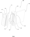
- the heat exchanger 100 for example a condenser 100, comprises a pair of manifolds 102A, 102B, a plurality of heat exchange tubes 106 and at least one connecting arrangement 104.
- the plurality of tubes 106 stacked between the manifolds 102A, 102B to provide a fluidal communication between the manifolds 102A, 102B.
- the pair of manifolds 102A, 102B may comprise a first manifold 102A and a second manifold 102B.
- the connecting arrangement 104 is configured to be fixed to at least one of the manifolds 102A, 102B, for example, the first manifold 102A of the heat exchanger 100.
- the connecting arrangement 104 comprises a first connecting element 108 having a first portion 112 and a second portion 114.
- the first portion 112 comprises a hollow portion 116 and at least one latch element 118.
- the first portion 112 may be a bracket configured to rotate the first connecting element 108 around the axis of the first manifold 102A.
- the latch element 118 is configured to immobilize the first connecting element 108 with respect to the manifold 102A at least in an axis perpendicular to the axis of elongation of the first manifold 102A.
- the second portion 114 includes a mounting feature adapted to be secured to a support structure of the vehicle (not shown in Figures).
- the support structure is a radiator.
- the support structure is a vehicle frame.
- the connecting arrangement 104 further comprises a second connecting element 110.
- the second connecting element 110 comprises a base portion 120 fixed to the first manifold 102A of the heat exchanger 100, a neck 122 extending from the base portion 120 and a block 124 extending from the neck 122.
- the base portion 120 is brazed or welded to the first manifold 102A of the condenser 100.
- the block 124 may have a shape complementary to the shape of the hollow portion 116 of the first connecting element 108, which allows the block 124 to be snugly received within the hollow portion 116 and enable coupling of the first connecting element 108 to the first manifold 102A.
- the hollow portion 116 may be a U-shaped channel.
- the first connecting element 108 may be made of material including, but not limited to, synthetic material.
- the second connecting element 110 may be made of metallic material including, but not limited to, aluminium.
- the hollow portion 116 extends parallelly with respect to the elongation axis the first manifold 102A.
- the hollow portion 116 enables rotation around the elongation axis of the manifold 102A to engage the first connecting element 108 thereof.
- the latch 118 element extends from a side of the hollow portion 116 adapted to engage with the manifold 108A to immobilize the first connecting element 108 with respect to the first manifold 102A at least in an axis perpendicular to the axis of elongation of the first manifold 102A.
- the block 124 fixed to the first manifold 102A enables coupling of the first connecting element 108 thereof.
- the hollow portion 116 is formed of a base 126 and a pair of spaced apart parallel sidewalls 128, 130 extending from opposing sides of the base 126.
- the pair of sidewalls 128, 130 comprise a first sidewall 128 and a second sidewall 130.
- the first sidewall 128 may be formed of an elongated section 132 that terminates with an arcuate end 134.
- the end 134 has a concave arcuate configuration.
- the arcuate end 134 adapted to act as a hook, such that, once the bracket hooks around the received block 124, it cannot be removed therefrom.
- the hollow portion 116 is formed of a base 126 and a pair of spaced apart parallel sidewalls 128, 130 extending from opposing sides of the base 126.
- the pair of sidewalls 128, 130 comprise a first sidewall 128 and a second sidewall 130.
- the first sidewall 128 may be formed of an elongated section 132 that terminates with an arcuate end
- the open end 136 facilitates the hollow portion 116 to hook around an end portion 140 of the block 124 and a remaining portion of the hollow portion 116 is introduced around the block 124 by rotating the hollow portion 116 around the block 124.
- the closed end 138 of the hollow portion 116 prevents further movement or slipping of the bracket longitudinally along an elongate axis of the block 124. However, rotation of the hollow portion 116 around the elongation axis of the block 124 is still possible.
- the first connecting element 108 is provided with a latch element 118 along at least one sidewall 128, 130.
- the at least one sidewall 128, 130 particularly, the second sidewall 130 formed as two spaced apart portions 130A, 130B extending from the side of the hollow portion 116.
- the latch element 118 disposed alongside and between the two spaced apart portions 130A, 130B.
- the latch element 118 is a clip. The clip is adapted to engage with the block 124 to prevent rotation of the first connecting element 108. Referring to FIG. 3 and FIG.
- the block 124 has a front surface 146, a rear surface 148 and side surfaces 150.
- the block 124 is substantially rectangular in shape have a portion complementary to the hollow portion 116.
- the hollow portion 116 generally has a U-shaped cross section.
- the portion of the block 124 including the front surface 146 and side surfaces 156 generally has a U-shaped cross section complementary to the U-shaped cross section of the hollow portion 116.
- the clip may comprise a widened elongated portion 160 that extends along the side surface 150 of the block 124, and terminates at its ends with hooks or clips with the rear surface 148 of the block 124.
- the end of the elongated portion 160 may comprise a tab 162 adapted to engage with or hook onto the flat rear surface 148 and prevent movement of the first connecting element 108 in a direction perpendicular to the axis of elongation of the first manifold 102A.
- the base 126 of the hollow portion 116 may comprise a front portion 152 and a rear portion 154.
- the front portion 152 may comprise a rib 156 disposed along a length of the hollow portion 116.
- the rib 156 may be complementary to a recess 158 formed along a length of the front surface 146 of the block 124.
- the rib 156 of the first connecting element 108 and the complementary recess 158 of the second connecting element 110 acts as a guide to position the hollow portion 116 in place over the block 124.
- the rib 156 generally has a u-shaped cross section, which is complementary to a U-shaped cross section of the recess 158.
- the second portion 114 is adapted to be secured to the support structure of the vehicle (not shown).
- the engaging element 114 may be a flat elongated member that extends from the rear portion 154 of the base 126 of the hollow portion 116 and terminates with an end. In one embodiment, the end of the engaging element 114 is directly welded or brazed to the support structure.
- the engaging element 114 includes the mounting feature (not shown) adapted to be secured to the support structure of the vehicle.
- the mounting feature is a bracket that could be fastened to the support structure.
- the mounting feature is an opening that could be screwed to the support structure.
- the present invention discloses a heat exchanger module.
- the module comprises a first heat exchanger, a second heat exchanger and the connecting arrangement 104.
- the first heat exchanger is the condenser 100.
- the second heat exchanger is the radiator.
- the connecting arrangement 104 is located between the heat exchangers so as to enable the second heat exchanger to rotate and couple around the axis of elongation of the first heat exchanger.
Landscapes
- Engineering & Computer Science (AREA)
- Physics & Mathematics (AREA)
- Thermal Sciences (AREA)
- Mechanical Engineering (AREA)
- General Engineering & Computer Science (AREA)
- Heat-Exchange Devices With Radiators And Conduit Assemblies (AREA)
Claims (15)
- Wärmetauscher (100), der Folgendes umfasst: ein Paar Verteiler (102A, 102B), wobei jeder Verteiler (102A, 102B) eine Längsausdehnungsachse umfasst;mehrere Rohre (106), gestapelt zwischen den Verteilern (102A, 102B), zum Bereitstellen einer Fluidkommunikation zwischen den Verteilern (102A, 102B), undzumindest eine Verbindungsanordnung (104), dazu ausgelegt, an zumindest einem der Verteiler (102A, 102B) befestigt zu werden, wobei die Anordnung (104) Folgendes umfasst: ein erstes Verbindungselement (108), das einen hohlen Teil (116) umfasst, der sich parallel bezüglich der Längsausdehnungsachse des zumindest einen Verteilers (102A) erstreckt, wobei der hohle Teil (116) Rotation um die Längsausdehnungsachse des Verteilers (102b) ermöglicht, um in Eingriff mit dem ersten Verbindungselement (108) davon zu kommen, und zumindest ein Verriegelungselement (118), das sich von einer Seite des hohlen Teils (116) erstreckt, dazu angepasst, in Eingriff mit dem Verteiler (102A) zu kommen, um das erste Verbindungselement (108) bezüglich des Verteilers (102A) zumindest in einer Achse senkrecht zur Längsausdehnungsachse des Verteilers (102A) zu immobilisieren, wobei der Wärmetauscher (100) ferner ein zweites Verbindungselement (110) umfasst, das einen Block (124) umfasst, der komplementär zum hohlen Teil (116) ist, wobei der Block (124) am Verteiler (102A) befestigt wird, um Koppeln des ersten Verbindungselements (108) davon zu ermöglichen, dadurch gekennzeichnet, dass der hohle Teil (116) eine Basis (126), zwei voneinander beabstandete Seitenwände (128, 130), die sich von einander gegenüberliegenden Seiten der Basis (126) erstrecken, ein offenes Ende (136) und ein geschlossenes Ende (138) umfasst.
- Wärmetauscher (100) nach Anspruch 1, wobei der hohle Teil (116) ein U-förmiger Kanal ist.
- Wärmetauscher (100) nach Ansprüchen 1 und 2, wobei der hohle Teil (116) einen U-förmigen Querschnitt aufweist und der Block (124) einen Teil mit einem U-förmigen Querschnitt aufweist, der komplementär zum hohlen Teil (116) ist.
- Wärmetauscher (100) nach Anspruch 1, wobei sich das offene Ende (136) des hohlen Teils (116) um einen Endteil (140) des Blockes (124) einhakt und um einen verbleibenden Teil des Blockes (124) rotiert, um das erste Verbindungselement (108) mit dem zweiten Verbindungselement (110) zu koppeln, und wobei das geschlossene Ende (138) dazu angepasst ist, Bewegung des ersten Verbindungselements (108) entlang der Längsausdehnungsachse des Verteilers (102A) zu verhindern.
- Wärmetauscher (100) nach Anspruch 1 und 2, wobei der Block (124) des zweiten Verbindungselements (110) eine Vertiefung (158) umfasst, die komplementär zu einer Rippe (156) ist, die sich von dem hohlen Teil (116) erstreckt, wobei die Rippe (156) in der Vertiefung (158) aufgenommen ist, das erste Verbindungselement (108) mit dem zweiten Verbindungselement (110) koppelnd.
- Wärmetauscher (100) nach Anspruch 1, wobei die Rippe (156) einen U-förmigen Querschnitt umfasst.
- Wärmetauscher (100) nach Anspruch 1, wobei die Vertiefung (158) einen U-förmigen Querschnitt umfasst.
- Wärmetauscher (100) nach Anspruch 1, wobei zumindest eine Seitenwand (128) distal in einer konkaven bogenförmigen Auslegung endet.
- Wärmetauscher (100) nach Anspruch 1, wobei sich zumindest eine Seitenwand (130) als zwei voneinander beabstandete Teile (130A, 130B) erstreckt.
- Wärmetauscher (100) nach Anspruch 1, wobei sich das Verriegelungselement (118) entlang zwischen den zwei voneinander beabstandeten Teilen (130A, 130B) erstreckt.
- Wärmetauscher (100) nach Anspruch 1, wobei das Verriegelungselement (118) ein Klip ist.
- Wärmetauscher (100) nach Anspruch 1, wobei der Block (124) Folgendes umfasst: eine vordere Oberfläche (146), eine hintere Oberfläche (148) und Seitenwände (150), die sich zwischen der vorderen Oberfläche (146) und der hinteren Oberfläche (148) erstrecken.
- Wärmetauscher (100) nach Anspruch 10 und 12, wobei das Verriegelungselement (118) einen länglichen Teil (160) umfasst, der sich entlang der seitlichen Oberfläche (150) des Blocks (124) erstreckt und an einem Ende abschließt, das eine Nase (162) aufweist, wobei die Nase (162) dazu ausgelegt ist, in Eingriff mit der hinteren Oberfläche (148) des Blockes (124) zu kommen, um Bewegung des ersten Verbindungselements (108) in eine Richtung senkrecht zur Längsausdehnungsachse zu verhindern.
- Wärmetauscher (100) nach Anspruch 1, wobei das erste Verbindungselement (108) ferner ein Eingriffselement (132) umfasst, das sich von der Basis (126) des hohlen Teils (116) erstreckt, um mit einem zweiten Wärmetauscher zu koppeln.
- Wärmetauschermodul, das Folgendes umfasst:
einen ersten Wärmetauscher nach Ansprüchen 1-14 und einen zweiten Wärmetauscher, dadurch gekennzeichnet, dass sich die Verbindungsanordnung (104) zwischen den Wärmetauschern befindet, um dem zweiten Wärmetauscher zu ermöglichen, um die Längsausdehnungsachse des ersten Wärmetauschers zu rotieren und zu koppeln.
Priority Applications (3)
| Application Number | Priority Date | Filing Date | Title |
|---|---|---|---|
| EP21195552.1A EP4148368B1 (de) | 2021-09-08 | 2021-09-08 | Wärmetauscher |
| CN202280066619.5A CN118235010A (zh) | 2021-09-08 | 2022-09-08 | 热交换器 |
| PCT/EP2022/075024 WO2023036885A1 (en) | 2021-09-08 | 2022-09-08 | A heat exchanger |
Applications Claiming Priority (1)
| Application Number | Priority Date | Filing Date | Title |
|---|---|---|---|
| EP21195552.1A EP4148368B1 (de) | 2021-09-08 | 2021-09-08 | Wärmetauscher |
Publications (2)
| Publication Number | Publication Date |
|---|---|
| EP4148368A1 EP4148368A1 (de) | 2023-03-15 |
| EP4148368B1 true EP4148368B1 (de) | 2024-08-07 |
Family
ID=77666387
Family Applications (1)
| Application Number | Title | Priority Date | Filing Date |
|---|---|---|---|
| EP21195552.1A Active EP4148368B1 (de) | 2021-09-08 | 2021-09-08 | Wärmetauscher |
Country Status (3)
| Country | Link |
|---|---|
| EP (1) | EP4148368B1 (de) |
| CN (1) | CN118235010A (de) |
| WO (1) | WO2023036885A1 (de) |
Families Citing this family (2)
| Publication number | Priority date | Publication date | Assignee | Title |
|---|---|---|---|---|
| EP4556838A1 (de) * | 2023-11-15 | 2025-05-21 | Valeo Systemes Thermiques | Dichtung für einen kondensator |
| LU505830B1 (en) * | 2023-12-18 | 2025-06-19 | Estra Automotive Systems Luxembourg S A R L | Heat exchanger assembly |
Family Cites Families (3)
| Publication number | Priority date | Publication date | Assignee | Title |
|---|---|---|---|---|
| PL360511A1 (en) * | 2003-06-05 | 2004-12-13 | Delphi Technologies, Inc. | Self-acting snap fastening assembly bracket |
| EP1589311B1 (de) * | 2004-04-19 | 2008-10-29 | Behr France Hambach S.A.R.L. | Wärmeübertrager, insbesondere für ein Kraftfahrzeug |
| EP2450658B1 (de) * | 2010-11-03 | 2016-06-29 | MAHLE Behr France Hambach S.A.S | Vorrichtung zur Befestigung eines Kondensators |
-
2021
- 2021-09-08 EP EP21195552.1A patent/EP4148368B1/de active Active
-
2022
- 2022-09-08 WO PCT/EP2022/075024 patent/WO2023036885A1/en not_active Ceased
- 2022-09-08 CN CN202280066619.5A patent/CN118235010A/zh active Pending
Also Published As
| Publication number | Publication date |
|---|---|
| EP4148368A1 (de) | 2023-03-15 |
| WO2023036885A1 (en) | 2023-03-16 |
| CN118235010A (zh) | 2024-06-21 |
Similar Documents
| Publication | Publication Date | Title |
|---|---|---|
| EP4148368B1 (de) | Wärmetauscher | |
| US6382312B2 (en) | Heat-exchange module, for a motor vehicle in particular | |
| US20020056541A1 (en) | Mounting structure for heat exchanger and duplex heat exchanger | |
| MXPA01002121A (es) | Modulo de intercambio de calor especialmente para un vehiculo automotor. | |
| US7121369B2 (en) | Frame for multiple vehicle heat exchangers | |
| JP2005532222A (ja) | 熱交換器支持システムおよびそれに関連させた熱交換器モジュール | |
| US6202737B1 (en) | Heat exchanger assembly for motor vehicle | |
| US7040380B1 (en) | Bracket for motor vehicle air conditioner heat exchanger | |
| US20090178781A1 (en) | Spring mounting feature for heat exchanger | |
| US9823027B2 (en) | Cooling module and method of assembly | |
| US7367379B2 (en) | Arrangement for securing a heat exchanger to another heat exchanger | |
| US11591028B2 (en) | Front end module assembly | |
| US10935331B2 (en) | Device for assembling a heat exchanger of an air-conditioning apparatus with a radiator for cooling the engine of a motor vehicle | |
| CN100458352C (zh) | 换热器的箱结构 | |
| CN110243204B (zh) | 换热器组件及安装换热器的方法 | |
| JP2008155739A (ja) | 車両用エアガイド | |
| JPH11192833A (ja) | 熱交換器組み合わせ構造及び一体型熱交換器 | |
| EP0938990B1 (de) | Wärmetauscher für Fahrzeuge, mit einem Fixier- und Positionierelement das aus dem Wärmetauscherkern vorspringt | |
| EP0869325A2 (de) | In Reihen integrierte Wärmetauscher | |
| JP2005104212A (ja) | クーリングモジュール | |
| JP3687150B2 (ja) | 熱交換器支持装置 | |
| EP0777097B1 (de) | Wärmetauscher, insbesondere Radiator für ein Kraftfahrzeug, mit einem Versteifungselement | |
| JP7484483B2 (ja) | 車両前部熱交換器用エアガイド構造 | |
| JP3625259B2 (ja) | 熱交換器 | |
| EP4050293A1 (de) | Wärmetauscheranordnung |
Legal Events
| Date | Code | Title | Description |
|---|---|---|---|
| PUAI | Public reference made under article 153(3) epc to a published international application that has entered the european phase |
Free format text: ORIGINAL CODE: 0009012 |
|
| STAA | Information on the status of an ep patent application or granted ep patent |
Free format text: STATUS: THE APPLICATION HAS BEEN PUBLISHED |
|
| AK | Designated contracting states |
Kind code of ref document: A1 Designated state(s): AL AT BE BG CH CY CZ DE DK EE ES FI FR GB GR HR HU IE IS IT LI LT LU LV MC MK MT NL NO PL PT RO RS SE SI SK SM TR |
|
| STAA | Information on the status of an ep patent application or granted ep patent |
Free format text: STATUS: REQUEST FOR EXAMINATION WAS MADE |
|
| 17P | Request for examination filed |
Effective date: 20230901 |
|
| RBV | Designated contracting states (corrected) |
Designated state(s): AL AT BE BG CH CY CZ DE DK EE ES FI FR GB GR HR HU IE IS IT LI LT LU LV MC MK MT NL NO PL PT RO RS SE SI SK SM TR |
|
| GRAP | Despatch of communication of intention to grant a patent |
Free format text: ORIGINAL CODE: EPIDOSNIGR1 |
|
| STAA | Information on the status of an ep patent application or granted ep patent |
Free format text: STATUS: GRANT OF PATENT IS INTENDED |
|
| RIC1 | Information provided on ipc code assigned before grant |
Ipc: F28F 9/013 20060101ALI20240123BHEP Ipc: F28F 9/00 20060101AFI20240123BHEP |
|
| INTG | Intention to grant announced |
Effective date: 20240226 |
|
| GRAS | Grant fee paid |
Free format text: ORIGINAL CODE: EPIDOSNIGR3 |
|
| GRAA | (expected) grant |
Free format text: ORIGINAL CODE: 0009210 |
|
| STAA | Information on the status of an ep patent application or granted ep patent |
Free format text: STATUS: THE PATENT HAS BEEN GRANTED |
|
| AK | Designated contracting states |
Kind code of ref document: B1 Designated state(s): AL AT BE BG CH CY CZ DE DK EE ES FI FR GB GR HR HU IE IS IT LI LT LU LV MC MK MT NL NO PL PT RO RS SE SI SK SM TR |
|
| REG | Reference to a national code |
Ref country code: GB Ref legal event code: FG4D |
|
| REG | Reference to a national code |
Ref country code: CH Ref legal event code: EP |
|
| REG | Reference to a national code |
Ref country code: IE Ref legal event code: FG4D |
|
| REG | Reference to a national code |
Ref country code: DE Ref legal event code: R096 Ref document number: 602021016720 Country of ref document: DE |
|
| REG | Reference to a national code |
Ref country code: LT Ref legal event code: MG9D |
|
| REG | Reference to a national code |
Ref country code: NL Ref legal event code: MP Effective date: 20240807 |
|
| PG25 | Lapsed in a contracting state [announced via postgrant information from national office to epo] |
Ref country code: NO Free format text: LAPSE BECAUSE OF FAILURE TO SUBMIT A TRANSLATION OF THE DESCRIPTION OR TO PAY THE FEE WITHIN THE PRESCRIBED TIME-LIMIT Effective date: 20241107 |
|
| REG | Reference to a national code |
Ref country code: AT Ref legal event code: MK05 Ref document number: 1711375 Country of ref document: AT Kind code of ref document: T Effective date: 20240807 |
|
| PG25 | Lapsed in a contracting state [announced via postgrant information from national office to epo] |
Ref country code: GR Free format text: LAPSE BECAUSE OF FAILURE TO SUBMIT A TRANSLATION OF THE DESCRIPTION OR TO PAY THE FEE WITHIN THE PRESCRIBED TIME-LIMIT Effective date: 20241108 Ref country code: NL Free format text: LAPSE BECAUSE OF FAILURE TO SUBMIT A TRANSLATION OF THE DESCRIPTION OR TO PAY THE FEE WITHIN THE PRESCRIBED TIME-LIMIT Effective date: 20240807 Ref country code: PL Free format text: LAPSE BECAUSE OF FAILURE TO SUBMIT A TRANSLATION OF THE DESCRIPTION OR TO PAY THE FEE WITHIN THE PRESCRIBED TIME-LIMIT Effective date: 20240807 Ref country code: PT Free format text: LAPSE BECAUSE OF FAILURE TO SUBMIT A TRANSLATION OF THE DESCRIPTION OR TO PAY THE FEE WITHIN THE PRESCRIBED TIME-LIMIT Effective date: 20241209 Ref country code: FI Free format text: LAPSE BECAUSE OF FAILURE TO SUBMIT A TRANSLATION OF THE DESCRIPTION OR TO PAY THE FEE WITHIN THE PRESCRIBED TIME-LIMIT Effective date: 20240807 |
|
| PG25 | Lapsed in a contracting state [announced via postgrant information from national office to epo] |
Ref country code: BG Free format text: LAPSE BECAUSE OF FAILURE TO SUBMIT A TRANSLATION OF THE DESCRIPTION OR TO PAY THE FEE WITHIN THE PRESCRIBED TIME-LIMIT Effective date: 20240807 |
|
| PG25 | Lapsed in a contracting state [announced via postgrant information from national office to epo] |
Ref country code: LV Free format text: LAPSE BECAUSE OF FAILURE TO SUBMIT A TRANSLATION OF THE DESCRIPTION OR TO PAY THE FEE WITHIN THE PRESCRIBED TIME-LIMIT Effective date: 20240807 |
|
| PG25 | Lapsed in a contracting state [announced via postgrant information from national office to epo] |
Ref country code: AT Free format text: LAPSE BECAUSE OF FAILURE TO SUBMIT A TRANSLATION OF THE DESCRIPTION OR TO PAY THE FEE WITHIN THE PRESCRIBED TIME-LIMIT Effective date: 20240807 Ref country code: IS Free format text: LAPSE BECAUSE OF FAILURE TO SUBMIT A TRANSLATION OF THE DESCRIPTION OR TO PAY THE FEE WITHIN THE PRESCRIBED TIME-LIMIT Effective date: 20241207 |
|
| PG25 | Lapsed in a contracting state [announced via postgrant information from national office to epo] |
Ref country code: HR Free format text: LAPSE BECAUSE OF FAILURE TO SUBMIT A TRANSLATION OF THE DESCRIPTION OR TO PAY THE FEE WITHIN THE PRESCRIBED TIME-LIMIT Effective date: 20240807 |
|
| PG25 | Lapsed in a contracting state [announced via postgrant information from national office to epo] |
Ref country code: RS Free format text: LAPSE BECAUSE OF FAILURE TO SUBMIT A TRANSLATION OF THE DESCRIPTION OR TO PAY THE FEE WITHIN THE PRESCRIBED TIME-LIMIT Effective date: 20241107 Ref country code: ES Free format text: LAPSE BECAUSE OF FAILURE TO SUBMIT A TRANSLATION OF THE DESCRIPTION OR TO PAY THE FEE WITHIN THE PRESCRIBED TIME-LIMIT Effective date: 20240807 |
|
| PG25 | Lapsed in a contracting state [announced via postgrant information from national office to epo] |
Ref country code: RS Free format text: LAPSE BECAUSE OF FAILURE TO SUBMIT A TRANSLATION OF THE DESCRIPTION OR TO PAY THE FEE WITHIN THE PRESCRIBED TIME-LIMIT Effective date: 20241107 Ref country code: PT Free format text: LAPSE BECAUSE OF FAILURE TO SUBMIT A TRANSLATION OF THE DESCRIPTION OR TO PAY THE FEE WITHIN THE PRESCRIBED TIME-LIMIT Effective date: 20241209 Ref country code: PL Free format text: LAPSE BECAUSE OF FAILURE TO SUBMIT A TRANSLATION OF THE DESCRIPTION OR TO PAY THE FEE WITHIN THE PRESCRIBED TIME-LIMIT Effective date: 20240807 Ref country code: NO Free format text: LAPSE BECAUSE OF FAILURE TO SUBMIT A TRANSLATION OF THE DESCRIPTION OR TO PAY THE FEE WITHIN THE PRESCRIBED TIME-LIMIT Effective date: 20241107 Ref country code: NL Free format text: LAPSE BECAUSE OF FAILURE TO SUBMIT A TRANSLATION OF THE DESCRIPTION OR TO PAY THE FEE WITHIN THE PRESCRIBED TIME-LIMIT Effective date: 20240807 Ref country code: LV Free format text: LAPSE BECAUSE OF FAILURE TO SUBMIT A TRANSLATION OF THE DESCRIPTION OR TO PAY THE FEE WITHIN THE PRESCRIBED TIME-LIMIT Effective date: 20240807 Ref country code: IS Free format text: LAPSE BECAUSE OF FAILURE TO SUBMIT A TRANSLATION OF THE DESCRIPTION OR TO PAY THE FEE WITHIN THE PRESCRIBED TIME-LIMIT Effective date: 20241207 Ref country code: HR Free format text: LAPSE BECAUSE OF FAILURE TO SUBMIT A TRANSLATION OF THE DESCRIPTION OR TO PAY THE FEE WITHIN THE PRESCRIBED TIME-LIMIT Effective date: 20240807 Ref country code: GR Free format text: LAPSE BECAUSE OF FAILURE TO SUBMIT A TRANSLATION OF THE DESCRIPTION OR TO PAY THE FEE WITHIN THE PRESCRIBED TIME-LIMIT Effective date: 20241108 Ref country code: FI Free format text: LAPSE BECAUSE OF FAILURE TO SUBMIT A TRANSLATION OF THE DESCRIPTION OR TO PAY THE FEE WITHIN THE PRESCRIBED TIME-LIMIT Effective date: 20240807 Ref country code: ES Free format text: LAPSE BECAUSE OF FAILURE TO SUBMIT A TRANSLATION OF THE DESCRIPTION OR TO PAY THE FEE WITHIN THE PRESCRIBED TIME-LIMIT Effective date: 20240807 Ref country code: BG Free format text: LAPSE BECAUSE OF FAILURE TO SUBMIT A TRANSLATION OF THE DESCRIPTION OR TO PAY THE FEE WITHIN THE PRESCRIBED TIME-LIMIT Effective date: 20240807 Ref country code: AT Free format text: LAPSE BECAUSE OF FAILURE TO SUBMIT A TRANSLATION OF THE DESCRIPTION OR TO PAY THE FEE WITHIN THE PRESCRIBED TIME-LIMIT Effective date: 20240807 |
|
| REG | Reference to a national code |
Ref country code: DE Ref legal event code: R119 Ref document number: 602021016720 Country of ref document: DE |
|
| PG25 | Lapsed in a contracting state [announced via postgrant information from national office to epo] |
Ref country code: DK Free format text: LAPSE BECAUSE OF FAILURE TO SUBMIT A TRANSLATION OF THE DESCRIPTION OR TO PAY THE FEE WITHIN THE PRESCRIBED TIME-LIMIT Effective date: 20240807 Ref country code: SM Free format text: LAPSE BECAUSE OF FAILURE TO SUBMIT A TRANSLATION OF THE DESCRIPTION OR TO PAY THE FEE WITHIN THE PRESCRIBED TIME-LIMIT Effective date: 20240807 |
|
| PG25 | Lapsed in a contracting state [announced via postgrant information from national office to epo] |
Ref country code: EE Free format text: LAPSE BECAUSE OF FAILURE TO SUBMIT A TRANSLATION OF THE DESCRIPTION OR TO PAY THE FEE WITHIN THE PRESCRIBED TIME-LIMIT Effective date: 20240807 |
|
| PG25 | Lapsed in a contracting state [announced via postgrant information from national office to epo] |
Ref country code: CZ Free format text: LAPSE BECAUSE OF FAILURE TO SUBMIT A TRANSLATION OF THE DESCRIPTION OR TO PAY THE FEE WITHIN THE PRESCRIBED TIME-LIMIT Effective date: 20240807 |
|
| PG25 | Lapsed in a contracting state [announced via postgrant information from national office to epo] |
Ref country code: SK Free format text: LAPSE BECAUSE OF FAILURE TO SUBMIT A TRANSLATION OF THE DESCRIPTION OR TO PAY THE FEE WITHIN THE PRESCRIBED TIME-LIMIT Effective date: 20240807 |
|
| REG | Reference to a national code |
Ref country code: CH Ref legal event code: PL |
|
| PG25 | Lapsed in a contracting state [announced via postgrant information from national office to epo] |
Ref country code: LU Free format text: LAPSE BECAUSE OF NON-PAYMENT OF DUE FEES Effective date: 20240908 |
|
| PLBE | No opposition filed within time limit |
Free format text: ORIGINAL CODE: 0009261 |
|
| STAA | Information on the status of an ep patent application or granted ep patent |
Free format text: STATUS: NO OPPOSITION FILED WITHIN TIME LIMIT |
|
| PG25 | Lapsed in a contracting state [announced via postgrant information from national office to epo] |
Ref country code: MC Free format text: LAPSE BECAUSE OF FAILURE TO SUBMIT A TRANSLATION OF THE DESCRIPTION OR TO PAY THE FEE WITHIN THE PRESCRIBED TIME-LIMIT Effective date: 20240807 |
|
| PG25 | Lapsed in a contracting state [announced via postgrant information from national office to epo] |
Ref country code: DE Free format text: LAPSE BECAUSE OF NON-PAYMENT OF DUE FEES Effective date: 20250401 |
|
| REG | Reference to a national code |
Ref country code: BE Ref legal event code: MM Effective date: 20240930 |
|
| PG25 | Lapsed in a contracting state [announced via postgrant information from national office to epo] |
Ref country code: BE Free format text: LAPSE BECAUSE OF NON-PAYMENT OF DUE FEES Effective date: 20240930 |
|
| 26N | No opposition filed |
Effective date: 20250508 |
|
| PG25 | Lapsed in a contracting state [announced via postgrant information from national office to epo] |
Ref country code: FR Free format text: LAPSE BECAUSE OF NON-PAYMENT OF DUE FEES Effective date: 20241007 |
|
| PG25 | Lapsed in a contracting state [announced via postgrant information from national office to epo] |
Ref country code: CH Free format text: LAPSE BECAUSE OF NON-PAYMENT OF DUE FEES Effective date: 20240930 |
|
| PG25 | Lapsed in a contracting state [announced via postgrant information from national office to epo] |
Ref country code: IE Free format text: LAPSE BECAUSE OF NON-PAYMENT OF DUE FEES Effective date: 20240908 |
|
| PG25 | Lapsed in a contracting state [announced via postgrant information from national office to epo] |
Ref country code: SE Free format text: LAPSE BECAUSE OF FAILURE TO SUBMIT A TRANSLATION OF THE DESCRIPTION OR TO PAY THE FEE WITHIN THE PRESCRIBED TIME-LIMIT Effective date: 20240807 |
|
| PG25 | Lapsed in a contracting state [announced via postgrant information from national office to epo] |
Ref country code: RO Free format text: LAPSE BECAUSE OF FAILURE TO SUBMIT A TRANSLATION OF THE DESCRIPTION OR TO PAY THE FEE WITHIN THE PRESCRIBED TIME-LIMIT Effective date: 20240807 |
|
| PG25 | Lapsed in a contracting state [announced via postgrant information from national office to epo] |
Ref country code: CY Free format text: LAPSE BECAUSE OF FAILURE TO SUBMIT A TRANSLATION OF THE DESCRIPTION OR TO PAY THE FEE WITHIN THE PRESCRIBED TIME-LIMIT; INVALID AB INITIO Effective date: 20210908 Ref country code: IT Free format text: LAPSE BECAUSE OF FAILURE TO SUBMIT A TRANSLATION OF THE DESCRIPTION OR TO PAY THE FEE WITHIN THE PRESCRIBED TIME-LIMIT Effective date: 20240807 |